the Creative Commons Attribution 4.0 License.
the Creative Commons Attribution 4.0 License.
 | 24 Nov 2021
Force analysis of minimal self-adaptive fingers using variations of four-bar linkages
Fadi Nassar
Lionel Birglen
This paper presents the design and optimization of four versions of self-adaptive, a.k.a. underactuated, fingers based on four-bar linkages. These fingers are designed to be attached to and used with the same standard translational grippers as one finds in the manufacturing and packaging industries. This paper aims at showing self-adaptive fingers as simply as possible and analysing the resulting trade-off between complexity and performance. To achieve this objective, the simplest closed-loop 1 degree-of-freedom (DOF) linkage, namely the four-bar linkage, is used to build these fingers. However, it should be pointed out that if this work does consider a single four-bar linkage as the basic building block of the fingers, four variations of this four-bar linkage are actually discussed, including some with a prismatic joint. The ultimate purpose of this work is to evaluate whether the simplest linkages for adaptive fingers can produce the same level of performance in terms of grasp forces as more complex designs. To this end, a kinetostatic analysis of the four fingers is first presented. Then, the fingers are all numerically optimized considering various force-based metrics, and results are presented. Finally, these results are analysed and prototypes shown.
- Article
(2671 KB) - Full-text XML
- BibTeX
- EndNote


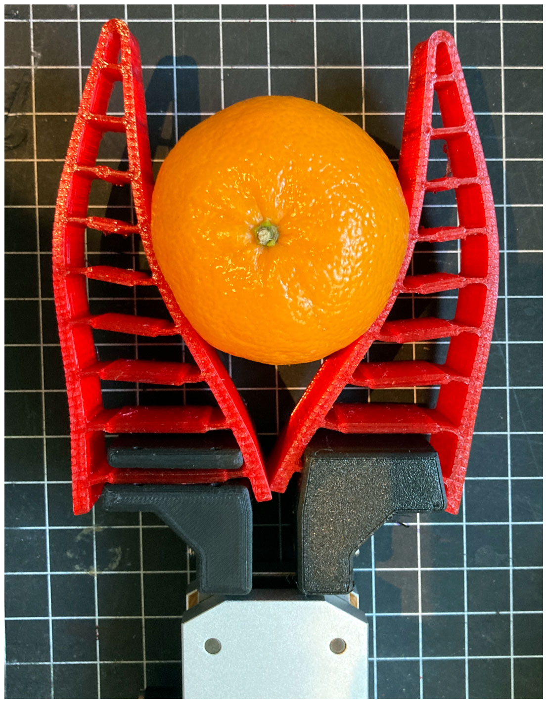
Self-adaptive, also known as underactuated (Birglen et al., 2007), hands and fingers have been used in the last decade by both the research community and the industry as a compromise between complex anthropomorphic robotic hands and classical industrial grippers. Complex dexterous hands could require more than three fingers and 9 actuated degrees of freedom (DOF) to become dexterous and provide sufficient motion capability for object manipulation, while classical industrial grippers are made for simpler tasks that only require a motion produced by a 1 DOF mechanism. Underactuated hands and fingers offer a simplicity in control not accessible to fully actuated designs since the number of actuators is smaller than the number of DOF. Often in an underactuated hand, a single actuator drives the whole hand. Additionally, underactuated hands are made not to depend on sensors for their operation while still having shape adaptation capabilities, i.e. being able to conform to a vast range of shapes of objects to grasp. Underactuated hands are also referred to as self-adaptive because of this property and to differentiate themselves from other applications of underactuation in robotics such as passive walkers. The first self-adaptive hand reported in the scientific literature was probably the Soft Gripper, introduced by Shigeo Hirose (Shigeo and Umetani, 1978), which was actuated by two wires and had two 10-phalanx fingers. Newer designs have been demonstrated since, commonly showing anthropomorphic inspiration but not exclusively (Begoc et al., 2007; Catalano et al., 2012; Dollar and Howe, 2006). Other robotic devices close to self-adaptive fingers have also been reported which use structural compliance to achieve conformal grasps. They are referred to as soft hands and grippers. Amongst these soft grippers, many can be found built using a particular design of bio-inspired fingers based on the Fin Ray Effect (FRE; see Fig. 1) (Crooks et al., 2017; Shan and Birglen, 2020) for which commercial products exist and are marketed by the company Festo. Underactuation and soft grasping are two common techniques to provide robotic systems with tools for securing and manipulating arbitrarily shaped objects.
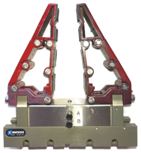
Commercial products exist for grasping hands, either relying on underactuated mechanisms or soft robotics techniques. For instance, Robotiq's 2F-85 and 2F-140 Adaptive Grippers, RightHand Robotics RightPick, Soft Robotics Inc. mGrip, or the Gripper Company fingers are all commercially available devices and are widely used in many markets. However, they are all new products, while the manufacturing and packaging industry has been using pneumatic parallel grippers in their operations for a very long time, and replacing them with any of these new designs is costly and time-consuming. The only commercial product not requiring the replacement of the end effectors in existing workcells is the FRE-based fingers from Festo since they can be simply attached to the gripper in place. Another similar solution avoiding the complete replacement of existing hardware was introduced in Carpenter et al. (2014) in which an adaptive jaw was proposed that can be secured to and driven by a parallel gripper. This adaptive jaw consists of three parallel hydraulic cylinders that are connected to a common local reservoir. By providing only an addition to a standard gripper, this solution eliminates the need to engineer a complex cable or linkage system to provide finger adaptability. Yet another solution, proposed by the second author and inspired by the FRE, consists in designing a passively adaptive linkage to be attached to standard industrial grippers; see Fig. 2 for an example. When in contact with an object, this linkage can deform in such a way that it provides an enveloping motion around the object it is in contact with. Actuation is thus provided by the motion of the gripper moving the base of the adaptive linkage but the latter embeds no actuation or sensing element. In Birglen (2015), such a linkage named the PaCoMe finger was introduced and consists in a three-phalanx self-adaptive mechanical finger. The proposed design is inspired by the FRE fingers but using rigid links instead of compliant ones and discards unnecessary crossbeams connecting the front and back of the fingers. The PaCoMe finger has 3 DOF and constitutes a closed-loop six-bar linkage in which specific joints embed a spring and a joint stopper. This finger was shown to produce stable enveloping and precision grasps while being attached to an off-the-shelf translational pneumatic gripper. An extension of this work was then demonstrated in Birglen (2019), based on a slightly simpler linkage and specifically designed to match the requirements of collaborative robotics applications. This second design was based on the idea that a transmission linkage producing full mobility to the phalanges might not be mandatory to achieve a successful grasp. The simpler mechanism presented in Birglen (2019) was shown to be a valid alternative to the original six-bar linkage version, based both on theoretical and experimental results shown in the paper. The same idea is also shown in Kok (2018) and Abdeetedal et al. (2018), where one 2 DOF finger and then one 1 DOF self-adaptive finger are introduced to be used with industrial parallel grippers. Finally, another example of a self-adaptive finger with 1 DOF is presented in Zheng and Zhang (2019), where a four-bar mechanism along with an eccentric cam is used.
This paper aims at continuing the discussion on this line of thought, namely producing self-adaptive fingers as simply as possible, by analysing the performance of designs with only a single DOF. To this end, four novel variations of self-adaptive designs are presented, all based on four-bar mechanisms. Two of these designs have two phalanges, while the other two have three. An uncommon feature of these designs is that two of them (one in each category: two- and three-phalanx fingers) use a prismatic joint. Prismatic joints in robotic fingers are not unheard of, but they are uncommon as they significantly depart from anthropomorphic inspiration. However, for industrial grasping, the main market of the previously mentioned commercial products, anthropomorphic designs are not necessarily relevant. The main contributions of this work are as follows:
-
the introduction of new, simple 1 DOF designs of linkage-based adaptive fingers, potentially including a prismatic joint,
-
the comparison of the performances produced by these fingers with other more complex designs, as previously reported in the literature.
Prototypes of the 3 DOF PaCoMe fingers based on six-bar linkages described in Birglen (2015) are shown in Fig. 2 where they are attached to a standard Schunk KGG 100-80 gripper. As mentioned before, these fingers are based on a single-loop linkage with six revolute joints only, and they have three phalanges. These phalanges are constituted by the three consecutive binary links central to the hand and connected by three revolute joints. Two additional links and three revolute joints are used to form the transmission linkage of the finger at the outer side of each finger. This transmission linkage aims at avoiding constraint of the DOF of the finger and ensuring that the allowed motion of the phalanges produces the desired shape-adaptation property for the mechanism. The revolute joints in the transmission linkage are equipped with springs with stoppers to fully constrain and preload the linkage when it is not subjected to external contacts at the phalanges. The last remaining link, i.e. the base of the linkage, is connected to the gripper movable jaw, whose motion is one of a prismatic joint. Thus, the gripper acts a linear actuator for the fingers. A simplified design of this design was shown in Birglen (2019) in which the finger only had 2 DOF, and there are kinematic couplings between the rotations of the phalanges.
Following this trend in decreasing the number of DOF in self-adaptive fingers to simplify manufacturing and decrease cost, this paper proposes to reduce the DOF one step further to a single one. While there are a multitude of 1 DOF grippers proposed in the literature, it should be made clear that the mechanisms proposed here are fundamentally different from these grippers. What is proposed here is a 1 DOF mechanical finger to attach to a separate 1 DOF gripper. Hence, the complete mechanism has 2 DOF: one for the finger and one for the gripper. Contact forces are provided at the finger only, and the gripper is creating the motion, closing the distance between the object and the mechanical finger. A 0 DOF finger could actually be made and would be a single rigid part. However, a 0 DOF finger would not be able to provide any shape adaptation. Hence, 1 DOF for an adaptive finger is the absolute minimal number of DOF one can use. Further highlighting the difference between the solution proposed here and simple articulated grippers, the mechanisms proposed here use two or three phalanges to envelop objects, while articulated 1 DOF grippers only create pinch grasps (a.k.a. precision grasps).
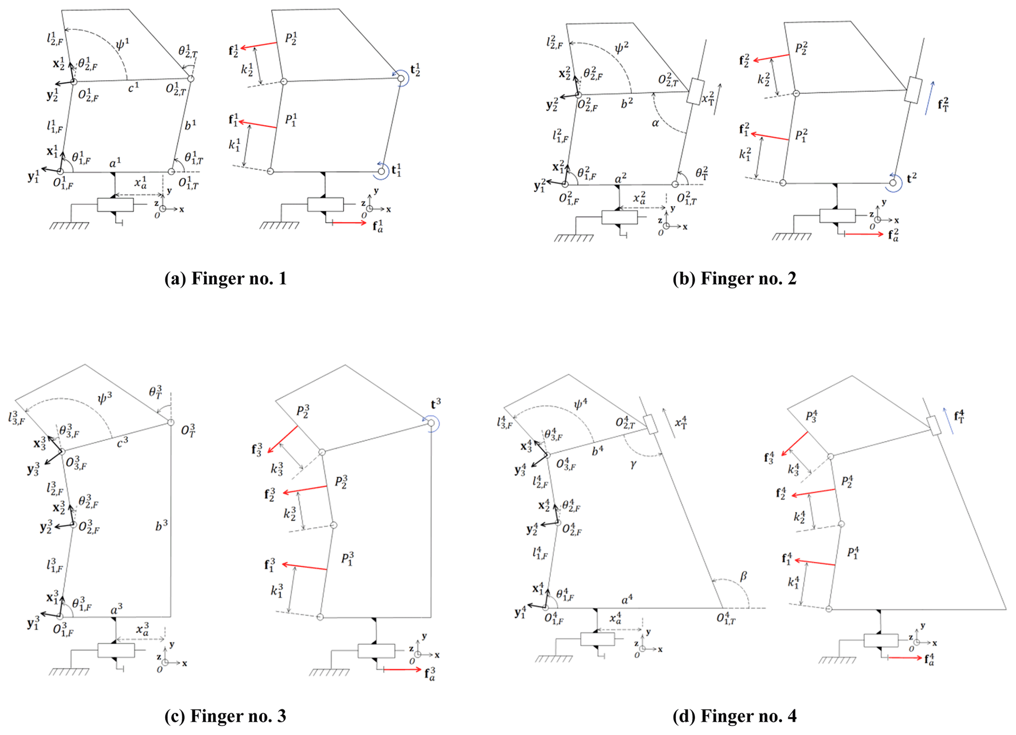
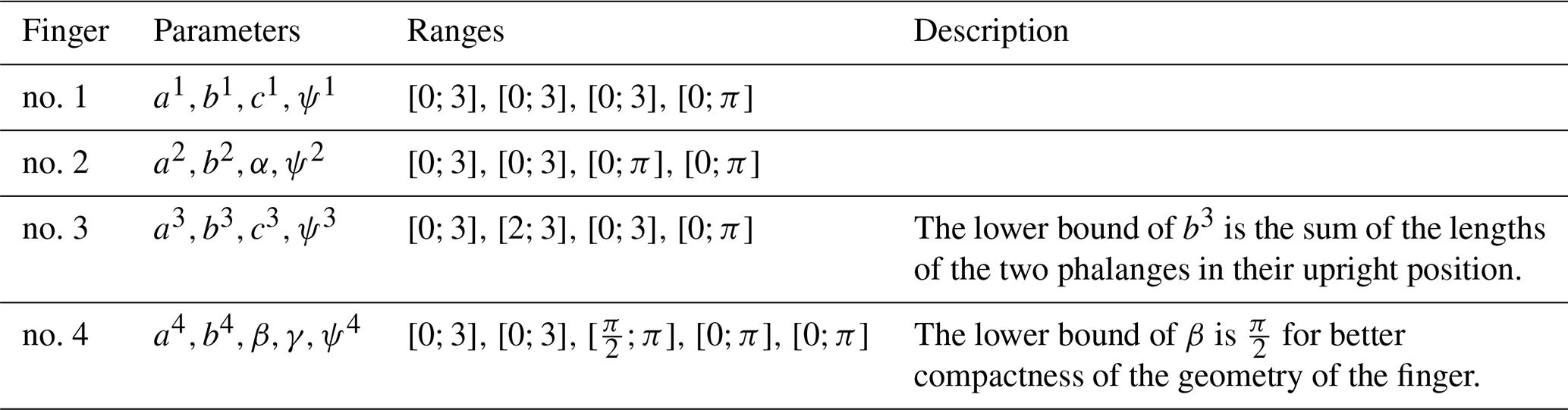
All the fingers proposed in this work are illustrated in Fig. 3. Points define the locations of the revolute joints constituting the phalanges of the finger no. i, where if the finger has two phalanges or if it has three. The length of the jth phalanx of the i finger is . Angles are the relative angles between these phalanges as shown in Fig. 3, and with these angles, one can define local frames for the phalanges (). On each phalanx there is a potential contact force at point modelled by vector and located at a distance from point at the base of the phalanx. The transmission linkage at the back of finger no. i is defined by points , where j=1 or depending on if this linkage needs to be defined with one or two points. The geometrical parameters of the transmission linkage, locating its revolute joints if there is one, are indicated by lower case roman letters ai,bi, etc. in alphabetical order, and the associated joint angle is , with j=1 or depending on the finger. If a prismatic joint is used in the transmission linkage, it is defined by a joint length , and the joint has angles α, β or γ between the direction of the motion and the links of the mechanism. Angles ψi are used to measure the angle between the distal phalanx contact surface of finger no. i and the line connecting this phalanx to the transmission linkage. Translational actuation of the fingers is defined with the horizontal position of the base of the finger to a fixed reference frame (Oxyz). The force in the prismatic joint modelling actuation is . The magnitudes of the forces and torques created by passive elements in the joints of the transmission linkage are measured by if the joint is of the revolute type (torque) and if it is a prismatic joint (force). The main geometric parameters of all four fingers are listed in Table 1.

Fingers no. 1 and no. 2 as defined in this paper have two phalanges, and their geometry as well as their associated parameters are shown in Fig. 3a and b. The transmission linkage of finger no. 1 is constituted by two revolute joints in points and connecting a single link at the back of the finger. To better illustrate the shape adaptation capability of these passive fingers, an example of the closing sequence of a particular design of finger no. 1 is shown in Fig. 4. The fingers are attached to a translational gripper and are closing on a slightly off-centered circular object. The fact that this object was not perfectly centered with respect to the gripper aims at illustrating how one finger can adapt to the object independently from the other. In general, with a synchronized gripper such as the one used in the depicted simulation (model KGG 100-80), the left and right jaw motions are necessarily mirroring each other. While the jaws have symmetric motions, this is not necessarily the case with the adaptive fingers attached on top of these jaws, and this property further expands the shape adaptability inherent to a single adaptive finger. The second finger with only two phalanges, namely finger no. 2, has a transmission linkage composed of one revolute and one prismatic joint in point and of direction respectively. The distal phalanx of finger no. 2 is rigidly connected to the prismatic joint as depicted with the connection to the long side of rectangle symbolizing the prismatic joint. The link of the transmission linkage, namely , slides inside this prismatic joint. Although only one spring in one joint of the transmission linkage in both these two mechanisms is enough to fully constrain them (they have 1 DOF), two springs are considered in the model proposed in this section to be more general and establish the impact of these springs on the contact forces if needed. The input motion for both fingers is the translation along the axis x created by the gripper, and this translation is associated with a force . Contact with an object can occur with either the proximal phalanx (points - or distal phalanx (starting in point and of length , with ), thereby creating a contact force at point or at point respectively. The quadrilateral at the top of the fingers, defined by constant angles ψ1 and ψ2, is the distal phalanges of these fingers, and these phalanges are rigid bodies, as the proximal ones are.
Figure 3c and d similarly illustrate the parameters of fingers no. 3 and no. 4. This time both mechanisms have three phalanges, and, thus, only a single joint remains for the transmission linkage (which in that sense is not “linkage” per se, being reduced to a joint). This remaining joint is either revolute for finger no. 3 or prismatic for finger no. 4. In the latter case, the distal phalanx is again rigidly connected to the prismatic joint. In both mechanisms, a spring is added to this last joint to statically constrain the finger in the absence of a contact, similarly to fingers no. 1 and no. 2. In all cases, when the translational gripper modelled by the prismatic joint at the base of the four mechanisms is driven, the finger is brought into contact with the object to be grasped, and this contact causes a motion of the linkages in reaction to the force arising at the connection, assuming the force of the gripper is sufficient to overcome friction at the contact point, as illustrated in Fig. 4. Similarly to fingers no. 3 and no. 4, the quadrilateral at the top of the fingers depicted in Fig. 3c–d is the distal phalanges of these fingers, which are rigid bodies.
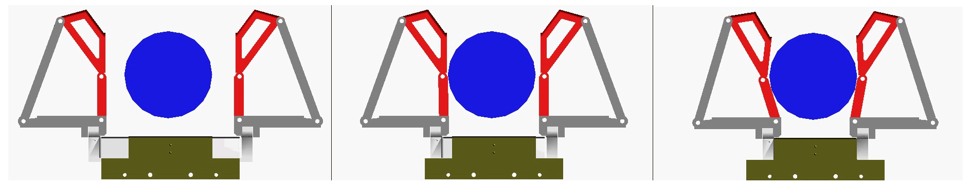
Figure 4Simulation of a closing sequence of a geometry of finger no. 1 mounted on a translational gripper.
In order to be able to compare between the four fingers modelled in this paper and the ones previously reported in the literature, two steps are required. As the performances of self-adaptive fingers are usually quantified by the magnitudes of the contact forces they produce, one must first establish these forces. Then, in a second step and to obtain a meaningful comparison, the fingers must be optimized with respect to these forces in a similar fashion as reported in the literature so that the best fingers possible are used for the comparisons, and these comparisons are meaningful. Assuming that dynamic forces are negligible, a common hypothesis in underactuated grasping since the masses and inertias of the links are usually relatively small, one can use the virtual work principle to calculate the generated contact forces. The total virtual work for each of the four fingers is
where the index i in Eq. (1) is used to denote which one of the four mechanisms is being considered (similarly to how the geometric parameters and forces were defined in Fig. 3). For example, δW1 is the virtual work of finger no. 1. Vector is the force associated with the linear actuator at the base of finger no. i, translating along the x axis. The infinitesimal motion of that base is . The contact force at the jth phalanx of finger no. i is , and the virtual displacement in the direction of this contact force is . The torques created by the various springs of the linkage are grouped in vector ti, and the infinitesimal relative rotation and/or displacement in the joint(s) of the transmission linkage are grouped in vector . In addition to the expression of this last vector, all other “T” in Eq. (1) denotes the mathematical transpose operator.
It should be noted that the expressions of ti and are different for each mechanism because of the differences in the transmission linkages and the number of springs; namely, one has
where and are the stiffnesses of the rotational and linear springs respectively that are used in the transmission linkages of the fingers. Angles and lengths are the initial values of the transmission linkage angles and displacements when the force or torque in the springs is equal to 0, and finally u4 is a unit vector along the axis of the prismatic joint of the transmission linkage if there is one.
All the fingers discussed in this paper have 1 DOF and can therefore be constrained by a single contact. Thus, two cases or contact scenarios are possible for fingers no. 1 and no. 2 since they have two phalanges, and three contact scenarios are possible for fingers no. 3 and no. 4 since these have three phalanges. A contact scenario is defined as a situation with one contact point at one specific phalanx. For a contact scenario j at the jth phalanx (counting from the base), the vector models the contact force in finger no. i. These forces are considered normal to the surface of the phalanges (i.e. neglecting friction) and acting along a vector with for fingers no. 1 and no. 2 and for fingers no. 3 and no. 4. Neglecting friction is unrealistic in practice, but this hypothesis is often made in the literature (e.g. Birglen 2015) for optimization purposes to yield the best mechanism possible from a kinematic perspective, i.e. without the help of friction during the grasp. Furthermore, friction does not affect the total squeezing force which is normal to the phalanges. The theoretical modelling of frictional contacts for underactuated fingers is presented in Birglen et al. (2007) with examples on the impact on grasp stability, and it is shown that friction indeed improves disturbance rejection and slippage prevention. Finally, the vector in Eq. (1) is defined by
where is the vector from point to the contact point , which is at a distance from the base of the corresponding phalanx. After equating the virtual work equation to zero in order to compute the contact forces at equilibrium, one obtains
where is the grasp Jacobian matrix and is the transmission matrix of finger no. i for contact scenario j. These matrices will be calculated for each mechanism in the next sections.
2.1 Jacobian matrix
By choosing the 2 DOF of the mechanisms (one for the finger and one for the actuation) as the translation xa and the angle where the contact occurs in a specific contact scenario, the Jacobian matrix can be defined for each contact scenario as
Again, fingers no. 1 and no. 2 have two phalanges, which means that there are only two contact scenarios possible, while fingers no. 3 and no. 4 have three contact scenarios since they have three phalanges. The Jacobian matrices can be calculated for each mechanism for each contact scenario by finding an expression of expressed as a function of and , which can be done by taking the time derivative of basic geometrical relationships. The results for all mechanisms and contact scenarios 1 and 2 (contact on the first two phalanges) are
The last case, namely contact scenario 3, for fingers no. 3 and no. 4, yields
In Eqs. (9)–(11), is a shorthand notation for and for , and is the length of the jth phalanx of finger no. i, while Xi, Yi, and Zi are angular velocity ratios defined as follows:
These equations can be used to express the Jacobian matrix in Eq. (8), and the components of the latter depend on the geometry of each four-bar mechanism, which is very different for each finger since they all have a unique combination of number of phalanges and type of joints.
2.2 Transmission matrix
The transmission matrix relates the displacements of the angles and/or distances of the joint(s) of the transmission linkage to the chosen DOF, as selected when computing the Jacobian matrix, for each mechanism. Its general form is
For fingers no. 1 and no. 2, the transmission linkage has two joints since it is formed by two rotational joints for finger no. 1 and one rotational and one prismatic for finger no. 2, so and are 1×2 vectors containing the displacements of the two angles and for the first and the displacements of the angle and the distance for the second one. and are then 2×2 matrices having zeroes in their first column and the velocity equations of the transmission linkage parameters for contact scenario j in their second column. For finger no. 1 one then has
For finger no. 2 these equations become
With fingers no. 3 and no. 4, their transmission “linkage” only has a single joint, revolute for finger no. 3 and prismatic for finger no. 4, and therefore, the expressions are a bit simpler. In these cases, and actually become a one-dimensional vector, i.e. a scalar value, representing the displacements of the angle and the distance respectively. Matrices and are then 1×2 vectors having zero as the first element and the velocity ratio of the transmission linkage joint to the selected DOF in contact scenario j as the second element. For finger no. 3, this gives
and for finger no. 4 one obtains
Substituting Eqs. (8)–(21) into Eq. (7), one can compute the generated contact forces at the phalanges for all fingers and all contact scenarios, as well as the gripper actuation force required for static equilibrium.
3.1 Fitness functions and variables
Once the contact force generated by a finger can be calculated as described in the Sect. 2, one can start the optimization process of these forces. The same fitness function needs to be used for the four mechanisms in order to have a standardized evaluation of their performances, and this function must be as close as possible to the ones used in the literature. In general, many different optimization criteria are used in the literature for underactuated robotic grippers (Kragten, 2010), but in the context of this work, three fitness functions were used:
-
the percentage of the positive contact forces generated over the workspace,
-
the average value of the coefficient of variation of the contact forces,
-
and the mechanical advantage of the mechanisms.
It is known that underactuated and self-adaptive fingers do not always generate positive contact forces at all phalanges in all configurations and this is one of their main drawbacks. Generating a negative contact force means that the finger has to pull on the surface of the object to be grasped, which is impossible in most cases. When negative contact forces occur, the finger can eventually lose contact with the object after sliding along its surface, a phenomenon known as ejection. It is desirable to minimize the occurrence of these negative forces, and this is the reason why this first fitness function, evaluating how often over the finger's workspace positive forces are encountered, is used both here and in the literature. The associated metric of performance can be written as
where μi is dimensionless and its maximal value is 1, and W is the workspace of the mechanism and is considered here to be in terms of the proximal phalanx angle range of motion since all the mechanisms have 1 DOF. The signum function is used to indicate the positiveness of the contact forces; i.e. signum is equal to 0 if the force that constrains the finger in the configuration set by is positive and equal to 1 otherwise. The scaling factor ni is the number of phalanges of the considered finger; it is equal to 2 for fingers no. 1 and no. 2 and equal to 3 for fingers no. 3 and no. 4. This scaling ensure that the performance index stays between 0 and 1. All integrands are one-dimensional and computed numerically in this paper by discrete sampling.
The second optimization criterion used in this paper is the average value of the coefficient of variation of the contact forces. The contact forces generated by the mechanism could be unbalanced even if they are always positive, and this is detrimental to the objective of securing objects of vastly different shapes and sizes. It is usually more desirable to even out the generated forces in the workspace of the fingers in order to be able to apply a relatively constant pressure on objects whatever their geometries. The average value of the coefficient of variation can be defined mathematically as
where si is the standard deviation of the contact forces for a defined design of finger no. i, and is the average value of these forces. The same definition for the signum function used in μi applies here for . The standard deviation shown in Eq. (23) is computed for a defined grasp configuration, so with only two or three elements. While this is a small number to compute standard deviations, the average value of the latter is computed over a large set of configurations and, therefore, becomes meaningful.
Finally, the third optimization criterion introduced here is the mechanical advantage of the mechanism. The forces generated by the fingers (while being positive and even with optimal coefficient of variation, i.e. of close magnitudes) could still be significantly weaker than the actuation force provided by the gripper. This decrease of the contact forces compared to the gripper's is detrimental if fine force control is required and also strongly weakens the grasp as one potentially “loses” a significant part of the actuation effort. This phenomenon was identified as one of the major weaknesses of FRE fingers in Carpenter et al. (2014) and can cause slippage of the object from the hand during high-speed pick and place operations. Quantifying the mechanical advantage of a self-adaptive finger gives an idea of the general efficiency of the fingers since it is in a sense the ratio between the gripper and the finger forces. Ideally, the contact force generated by the finger onto an object should be equal to the closing force delivered by the translational actuator at the base to maximize the efficiency. The mathematical equation for the mechanical advantage can be written as
To integrate this equation into the optimization process, the first step is to normalize the values of this mechanical advantage to get values ranging from 0 to 1. The second step is to calculate its average for each contact scenario j and, finally, to calculate the average of 1 minus the value calculated in step 2 (the optimal value for the mechanical advantage is 1 in Eq. (24), but for optimization we need to minimize performance metrics). The mathematical equation for the mechanical advantage performance index used in this paper thus becomes
where maximal and minimal values are again numerically computed. With all the fingers in this paper and similarly to what is found in the literature, the position of the contact force on each phalanx is assumed to be mid-phalanx. The workspace W is chosen as
and one can calculate all the other angles and lengths of the four-bar linkages using textbook formulae for this range of input angles. The constants during the optimization are the lengths of the phalanges , which are taken to be unitary for simplicity, and the stiffnesses of the springs used in the transmission linkage, also taken to be unitary. The same procedure can be repeated with other ratios of phalanx lengths if needed. The remaining geometrical parameters to be optimized are presented in Table 2. To optimize these mechanisms, the genetic algorithm from Mathworks' MATLAB is used. All the values of the parameters in each generation including the initial population are constrained in a range of values delimited by a lower and upper bound shown in Table 2. The upper bound for all the dimensions is set to be 3 to maintain a reasonable level of compactness for the fingers. The higher the upper limit on the link lengths is, the less compact the resulting finger becomes, as also discussed in Birglen (2019) where a Pareto plot is shown to illustrate the trade-off between compactness and performance: usually larger links provide a greater chance to obtain high performance since by restricting link lengths, the design space shrinks. The maximal number of generations is set to 1000, and the algorithm also stops if the average relative change in the best fitness function value over 500 generations is less than or equal to its standard tolerance. Convergence is generally achieved within 700 generations with slight differences for each finger. The genetic algorithm minimizes a single value for each finger, fi, which is a combination of the three fitness functions described in Eqs. (22), (23), and (25). The weights for the functions are distributed as follows: 50 % for the mechanical advantage, 40 % for the percentage of the positive contact forces, and 10 % for the average value of the coefficient of variation of the contact forces. With the number of variables being four with a relatively large range of values in conjunction with complex nonlinear objective functions, there are actually many local minima that are difficult to avoid without a heuristic method such as genetic algorithms as discussed in Boucher and Birglen (2017) which is why this optimization method was used.
3.2 Results and discussions
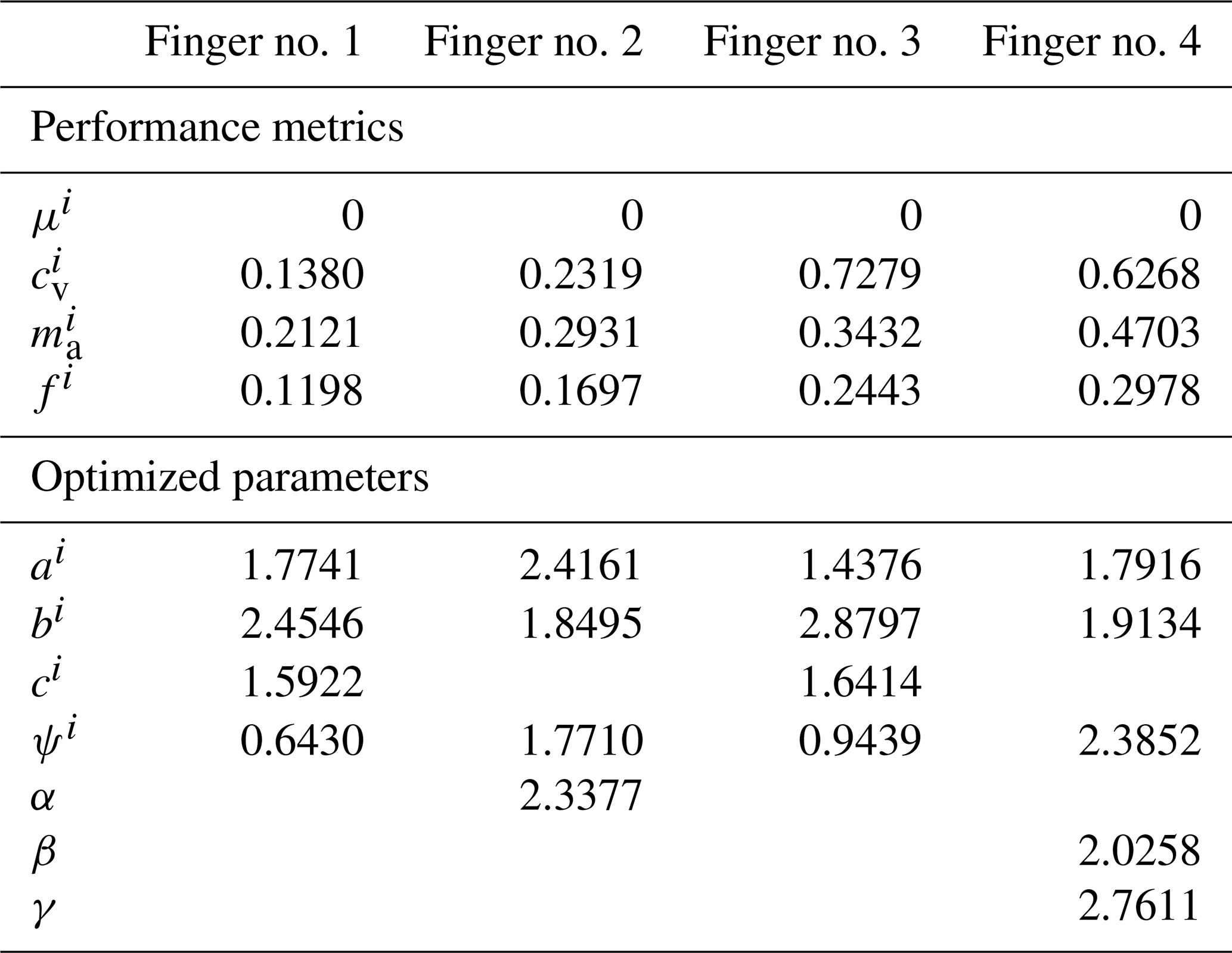
Table 3 and Fig. 5 present and illustrate the values of the optimized parameters and the values of the optimization functions for all the fingers. All these optimized fingers generate positive contact forces exclusively throughout their workspaces since the value of μi is zero for all the mechanisms. In terms of the average values of the coefficient of variation of the contact forces, it can be seen that the fingers with two phalanges demonstrate generally better performance than the fingers with three phalanges. Indeed, finger no. 1 has the lowest value with , followed by finger no. 2, then finger no. 4, and lastly finger no. 3 with . Intuitively, this remark seems to make sense as two-phalanx fingers have fewer potential cases of generated forces to maintain the finger in a specific configuration (they have two possible scenarios for one configuration, while the three-phalanx fingers have three), and it becomes harder to keep all the generated forces close in terms of magnitude when the number of possible contact points increases. What is more interesting is the quantification of this effect. Additionally, comparisons between fingers with the same number of phalanges still hold. As for the mechanical advantage of the fingers, it is seen that finger no. 1 has the best value with . This means that, out of the four fingers, finger no. 1 is able to transmit the gripper force from the linear actuator to the object with the least amount of weakening.
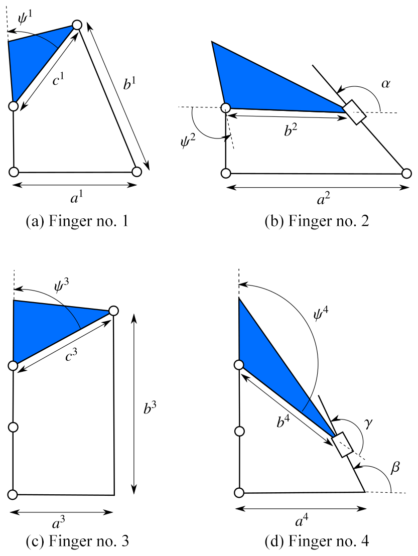
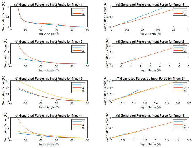
Figure 6Plots of the generated forces as a function of the input angle and the gripper force for the four fingers.
As for the forces, plotted in Fig. 6a for finger no. 1, and have relatively close values for any input angle, meaning that for a specific pose of that finger, the generated force from contact at the proximal phalanx has approximately the same magnitude as one generated at the distal phalanx. The only notable deviation is within the range , where is slightly greater by a margin of 0.1 N, which might be considered negligible but is noticeable considering that the maximal value of both generated forces in this plot is 1 N. One can also notice from the plot in Fig. 6b that the actuation force of the translational gripper is transmitted in a different manner to the contact point on each phalanx. Indeed, even though both plots show that the contact forces grow almost linearly with the gripper force, the slope of the plot corresponding to the force is greater than that of the one corresponding to , meaning that the same gripper force generates a noticeably greater contact force on the proximal phalanx (0.7 N) than on the distal phalanx (0.5 N), and this phenomenon becomes more and more prominent for an actuation force N or for an input angle .
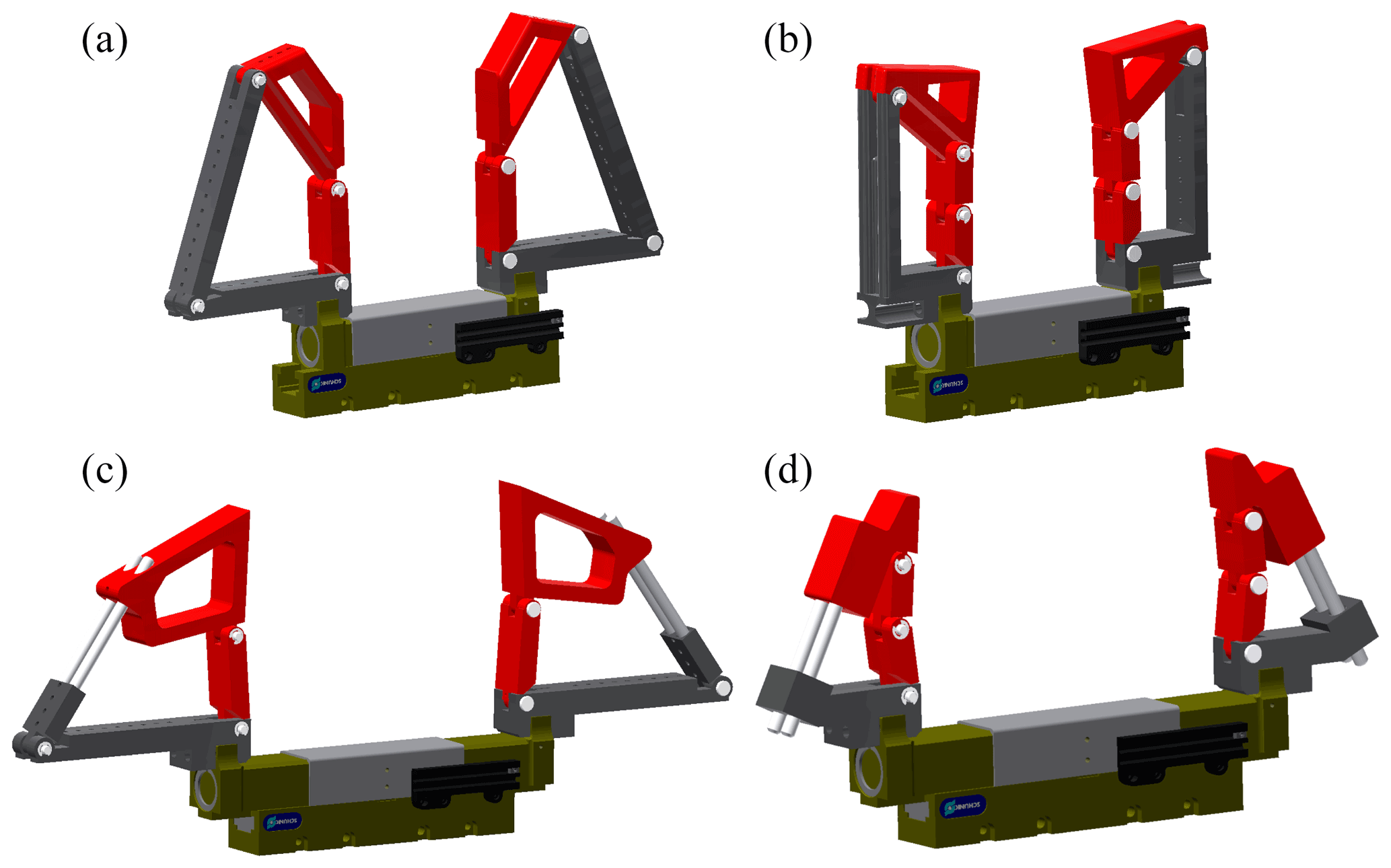
Figure 7CAD models for the optimal designs of the fingers; the gripper is shown in the closed (a, b) and open (c, d) positions.
For finger no. 2, it can be seen in Fig. 6c that the generated contact force on the proximal phalanx is again very close to the generated contact force on the distal phalanx for a range of configurations where . When this angle is such that , forces are higher, but the value of is significantly greater than that of (the overall maximal value of is 4 N greater than that of . Figure 6d on the other hand shows again an almost linear relationship between and with a slope approximately equal to 1 and a different, slightly less linear, plot for . For this mechanism also, the transmission of the actuation force to the contact points of the phalanges is better at the proximal phalanx since the corresponding plot of the force is in its entirety above the one for the distal phalanx, meaning that for the same gripper force, the output force is greater at the proximal phalanx than at the distal one. One can notice that the plots of the seems to abruptly end in Fig. 6d. This is because the figure is showing the comparative range of the phalanx forces to the gripper force. The fact that spans a smaller horizontal range in Fig. 6d actually means that exhibits a smaller range of magnitudes compared to when contact occurs at the distal phalanx () over the workspace of the finger; i.e. and both reach higher values for a full range of input rotation (over the workspace W).
For finger no. 3, one can divide the workspace into roughly two parts based on the plot shown in Fig. 6e: for , the value of the generated contact force on the distal phalanx is less than that of the generated forces on the proximal and intermediate phalanges and , which are themselves relatively close to each other for the same input angle. For , all of the contact forces at all the phalanges are very close to each other. As seen in Fig. 6f, the force delivered by the translational actuator is distributed in a relatively even manner among the phalanges since the values of the generated forces in each contact scenario (meaning at the proximal, intermediate, or distal phalanx) are close to the same gripper force . It should also be pointed out that this finger has the lowest maximal values for both the generated contact forces (0.35 N), (0.4 N), and (0.6 N) and the actuation force in the base (0.6 N), and that is because the transmission angle does not show a large range of motion throughout the workspace. Hence, the finger is not generating a strong torque in the spring of the transmission joint. This issue could be resolved quite simply by increasing the stiffness of the spring in the joint in the transmission linkage, thereby increasing all the forces.
Finally, for finger no. 4 Fig. 6g illustrates that all the phalanges generate contact forces that have very close values when . But when , the force generated by the intermediate phalanx is noticeably greater than that generated by the proximal and distal phalanges and , which, in turn, have close values for the same configuration of the finger (same input angle). In Fig. 6h, one can see that the intermediate phalanx has the ability to generate much greater forces than the proximal and distal phalanges. Indeed, the maximum value for in the workspace of the finger is 4 N for a gripper force of 3.5 N, while the maximum generated forces by the proximal and distal phalanges are 1 N each for a gripper force of 0.6 N and 1.2 N respectively, and this phenomenon is due to the geometry of the finger and the difficulty to transmit a force acting on the intermediate phalanx to cause a sliding in the joint of the transmission linkage.
Finally, for the comparison with more complex linkages previously shown in the literature, if one looks at Birglen (2019), the best percentage of the workspace corresponding to fully positive contact forces is reported to reach 9.7 %, and the average coefficient of variations of the contact forces is 0.73. Considering the second reference design proposed in Kok (2018), a value of 7 % is reported for the positive contact force workspace. With all the fingers presented in this paper, the achieved percentage of positive contact forces in the workspace is 100 %. Therefore, from this metric, there seems to be a clear advantage of using simpler linkages. The coefficient of variation of the optimized fingers of this paper with the same number of phalanges as in Birglen (2019) is of similar magnitude, but the ones with fewer phalanges are 2 to 3 times better.
This paper presented four different designs of self-adaptive mechanical fingers that can be actuated by the standard translational grippers used in the industry to transform these grippers into complete underactuated hands. The four designs are simple in terms of kinematics when compared to previous prototypes from the literature since all of them are based on variations of four-bar mechanisms and, thus, have only 1 DOF. Prismatic joints were also considered in two of these four fingers, which is uncommon in artificial fingers, even industrial ones. A general kinetostatic analysis was first presented in which a Jacobian and transmission matrix were calculated for each finger and for each of the defined contact scenarios in order to compute the contact forces generated by the different fingers. Then, optimization criteria were discussed for the evaluation of the performances of the fingers. The three optimization functions used in this paper, namely the percentage of the workspace where positive contact forces are generated by the mechanisms, the average value of the coefficient of variation of the contact forces, and the mechanical advantage of the mechanisms, gave a better understanding of the magnitude and variations of the generated contact forces between different phalanges. Although the mechanisms are simple in terms of geometry, their performances can be considered at least comparable with other prototypes with greater mobility (more DOF) or even better. However, it should be noted that the optimization was focused exclusively on the generated forces, and the enveloping capability of the fingers was not taken into consideration, and simulations show that fingers with rotational joints tend to have better enveloping grasps than the ones using a translational joint. This does not mean that using a prismatic joint in underactuated fingers will definitely lead to poor enveloping grasps, but the same finger optimization routine could give very different results if the ability to generate enveloping grasps were explicitly considered. Future works include manufacturing and experimental validation of the effectiveness of the optimal designs presented in this work and shown in Fig. 7.
Code can be freely accessed at https://github.com/LionelBirglen/SelfAdaptiveFinger_Version4B (Nassar and Birglen, 2021) under MIT License conditions.
The data are available upon request from the corresponding author.
FN conducted the mathematical modelling, programmed all MATLAB functions used for the paper including those needed the optimizations, produced Figs. 3 and 6, analysed the data, and prepared the manuscript. LB provided the original idea for the work, the four kinematic designs of the fingers, and the methodology, produced Figs. 1, 2, 4, 5, and 7, designed the CAD models of the prototypes, and revised the manuscript.
Some authors are members of the editorial board of MS. The peer-review process was guided by an independent editor, and the authors have also no other competing interests to declare.
Publisher’s note: Copernicus Publications remains neutral with regard to jurisdictional claims in published maps and institutional affiliations.
This paper was edited by Mohamed Amine Laribi and reviewed by Araceli Zapatero and one anonymous referee.
Abdeetedal, M. and Kermani, M. R.: Grasp and stress analysis of an underactuated finger for proprioceptive tactile sensing, IEEE/ASME Trans. Mech., 23.4, 1619–1629, 2018.
Begoc, V., Krut, S., Dombre, E., Durand, C., and Pierrot, F.: Mechanical design of a new pneumatically driven underactuated hand, Proceedings 2007 IEEE International Conference on Robotics and Automation, 927–933, 2007.
Birglen, L.: Enhancing versatility and safety of industrial grippers with adaptive robotic fingers, 2015 IEEE/RSJ international conference on intelligent robots and systems (IROS), 2015.
Birglen, L.: Design of a partially-coupled self-adaptive robotic finger optimized for collaborative robots, Autonomous Robots, 43.2, 523–538, 2019.
Birglen, L., Laliberté, T., and Gosselin, C. M.: Underactuated robotic hands, Vol. 40, Springer, New-York, USA, 2007.
Boucher, J.-M. and Birglen, L.: Performance Augmentation of Underactuated Fingers' Grasps Using Multiple Drive Actuation, ASME J. Mech. Robot., 9, 041003, https://doi.org/10.1115/1.4036220, 2007.
Carpenter, R., Hatton, R., and Balasubramanian, R.: Comparison of contact capabilities for underactuated parallel jaw grippers for use on industrial robots, International Design Engineering Technical Conferences and Computers and Information in Engineering Conference, Vol. 46377, American Society of Mechanical Engineers, 2014.
Catalano, M. G., Grioli, G., Serio, A., Farnioli, E., Piazza, C., and Bicchi, A.: Adaptive synergies for a humanoid robot hand, 12th IEEE-RAS International Conference on Humanoid Robots (Humanoids 2012), 2012.
Crooks, W., Rozen-Levy, S., Trimmer, B., Rogers, C., and Messner, W.: Passive gripper inspired by Manduca sexta and the Fin Ray® Effect, International Journal of Advanced Robotic Systems, 14.4, 1729881417721155, 2017.
Dollar, A. M. and Howe, R. D.: A robust compliant grasper via shape deposition manufacturing, IEEE/ASME transactions on mechatronics, 11.2, 154–131, 2006.
Kok, Y. Y.: Design and Evaluation of an Underactuated Adaptive Finger for Parallel Grippers, 2018 15th International Conference on Control, Automation, Robotics and Vision (ICARCV), 2018.
Kragten, G. A.: The ability of underactuated hands to grasp and hold objects, Mech. Mach. Theor., 43.3, 408–425, 2010.
Nassar, F. and Birglen, L.: Matlab Functions for Computing Contact Forces of Self-Adaptive Fingers based on Four-bar Linkages, available at: https://github.com/LionelBirglen/SelfAdaptiveFinger_Version4B, last access: 22 November 2021.
Shan, X. and Birglen, L.: Modeling and analysis of soft robotic fingers using the fin ray effect, Int. J. Robot. Res., 39.14, 1686–1705, 2020.
Shigeo, H. and Umetani, Y.: The development of soft gripper for the versatile robot hand, Mech. Mach. Theor., 13.3, 351–359, 1978.
Zheng, E. and Zhang, W.: An underactuated PASA finger capable of perfectly linear motion with compensatory displacement, J. Mech. Robot., 11.1, 014505, https://doi.org/10.1115/1.4041786, 2019.