the Creative Commons Attribution 4.0 License.
the Creative Commons Attribution 4.0 License.
 | 22 Nov 2021
Design and motion analysis of a small motor stator multi-wire paralleled winding hybrid robot
Yanling Zhao
Enwen Zhou
Jingwei Zhang
Chunya Wu
Chuang Yang
The working space of small motor stators is narrow, and most of them are manual winding. It is difficult to guarantee the uniform arrangement of enameled wires by multi-wire winding. To solve these problems, a three-phase parallel equivalent multi-wire winding robot is proposed to achieve large output torque of the motor. Firstly, according to the equivalent model, the structure of the large arm, small arm and manipulator is designed to determine the motion model of the winding robot. Euler's kinematics theory is used to analyze the change of the working position of the arm, and the rotation matrix of the arm and the constraint equation of the motion vector of each branch chain are established. The motion model of the arm and the manipulator are established using inverse kinematics and analytical analysis. The motion pose of each joint of the winding robot is studied to ensure that the robot realizes a three-phase parallel multi-wire winding motion. ADAMS software was used for kinematic simulation analysis of the winding robot. The displacement of the branch chain on the xyz axis was represented by the torque of the virtual motor to verify the correctness of the inverse kinematics solution and the closure condition of the manipulator block. Finally, the ROS simulation platform is built to simulate the joint motion planning of the winding robot to verify the multi-line parallel principle and the feasibility of the multi-line parallel winding hybrid robot. The research results of this paper provide a theoretical reference for multi-wire parallel winding equipment control.
- Article
(7328 KB) - Full-text XML
- BibTeX
- EndNote


Electric vehicles will be the main means of transportation in the future. The National Development and Reform Commission of China expects the number of them to reach 400 million by 2050. As an important component of electric vehicles (Zhu et al., 2016), small-size motors use multiple-wire winding instead of single-wire winding to meet the technical demand of large output torque (Liang et al., 2013), which is particularly important to ensure the working performance of the motor. At present, multiple-wire winding stators mainly adopt the method of manual winding, and the motor is burnt out due to the symmetry of the stator winding being poor, caused by uneven winding, which has become one of the most important factors when considering the faults of small-size motors (Hao et al., 2016); therefore the small electric mechanical industry is badly in need of automation equipment to realize multiple-wire, high-speed, high-precision winding.
Domestic and foreign scholars have studied winding patterns, method and equipment. Focusing on the nonuniform winding problem, Xia et al. (2012) proposed two design methods for optimizing coil parameters and explored the best technique route for the nonuniformly distributed equal ampere-turns. Gao et al. (2018) proposed an adaptive yaw control method of flexible press roll for the nonuniform thickness of the winding layer, aiming at the uniform arrangement of winding points. He et al. (2009) established a fiber stable winding mathematical model and provided an algorithm implementation process based on the stress analysis of fiber winding in response to the complex body winding problem. Qian et al. (2020) proposed a winding path design method combining grid winding with conventional winding, aiming at the S-duct winding problem composed of two elbow pipes with different turning radii. Looking at multiple grooves existing in the single-wire winding motor that needs to be wound (Wang et al., 2010), domestic scholars proposed a threading winding and automation winding machine suitable for small-size motor stators. Aiming at the automation problem of single-wire winding, Krim et al. (2019) produced an NOL nozzle winding machine, which adopts an automation transmission unit and can be freely arranged in the production line. Stephen J. Dodds of the University of East London proposed a robust tension control system for a sort of winding machine, aiming at the problem of the length and stability of velocity variation. Leif Svensson from Germany analyzed and optimized the mode of production and the manufacturing process characteristics of unconventional winding to improve the cost and performance of the winding machine (Dodds, 2011), focusing on the winding efficiency problem. Nikonov et al. (1986) from Russia developed the Nvs23A series winding machine, aiming at the pole groove structure of the stator, and used the manufacturing technique of indirect embedding technology to complete single-wire stator winding.
To sum up, domestic and foreign scholars have studied the single-wire winding method and equipment, but the multiple-groove stator winding method and related theories of small-size motors have not been reported on. Because the multiple winding stator needs more varnished wire embedded in the slot pole than the single winding stator, existing single-wire winding methods and equipment can not complete the winding, which makes the automation of multiple-wire winding difficult to realize. Therefore the three-phase parallel equivalent winding model is established based on stator winding craft. According to the model, the winding robot is designed according to a hybrid mechanism, and its kinematic model is established for analysis and calculation. Simulation technology is used to verify the feasibility of multiple-wire winding realized by the hybrid winding robot and provides the basis for the study of multiple-wire winding automation equipment.
The stator frame of the small-size motor stator is divided into 12 stages and three phases (U, V and W phase); each phase contains four turns, each turn is winded three times and each time 10 enameled wires are winded at the same time. The diameter of the motor stator ranges from 60–100 mm, and the diameter of enameled wires ranges from 0.1–1.0 mm. According to the above stator winding technology, the three-phase parallel equivalent winding model is designed as shown in Fig. 1. The winding process is divided into three phases: winding, arranging and pushing.
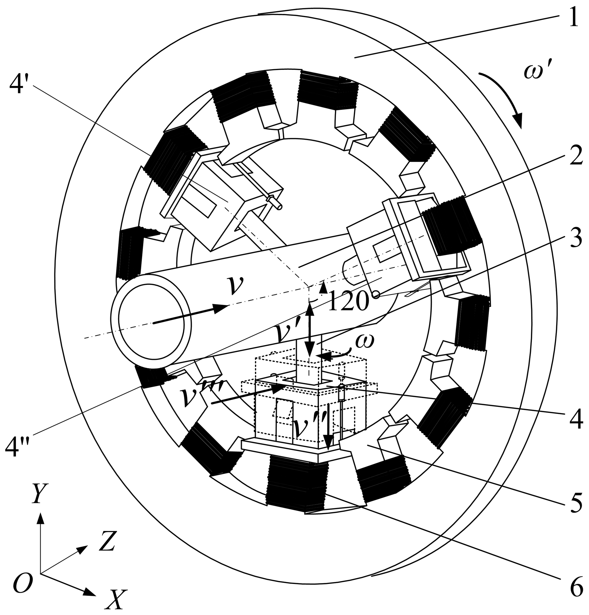
Figure 1Three-phase parallel equivalent winding model. (1) Stator, (2) the arm of robot, (3) the forearm of robot, (4) transfer arm, (5) turn and (6) enameled multi-wire in parallel.
The working transfer arm in the forearm has an angular speed ω rotation and moves along the stator radial direction with speed v′ to complete the winding and arranging phase. The arm drives three transfer arms to reach the specified station with speed v. The transfer arm pushes multiple wires parallel to the enameled wire into the turn of the stator with speed v′′ to realize the winding process of 10 enameled wires of three turns once, and then the stator is rotated in a 90∘ turn. The robot repeats the above action until it completes the stator winding of multiple wires.
According to the three-phase parallel equivalent winding mode, the whole structure of the winding hybrid robot is designed in this paper. The big arm is a parallel mechanism as shown in Fig. 2. Three branch chains all have a 4R structure, which ensures that sufficient degrees of freedom are provided for winding. The middle rod 3 is connected to the base, and the middle rod 7 is connected to the moving platform. The bevel gear rotates to transfer the power to the moving platform through the branch chain, so that the attitude angle of the big arm connecting rod changes, and motion is transferred to the forearm through the connection of the revolute joint. Under normal operation, the bevel gear groups of three branch chain can complete multiple-wire parallel winding with the same speed. When there is abnormal operation of the big arm, the offset center or one of the forearms stretches out. The bevel gear groups of three branch chain can adjust the position of the moving platform through the rotation speed to realize normal operation, then the motion of winding is completed.
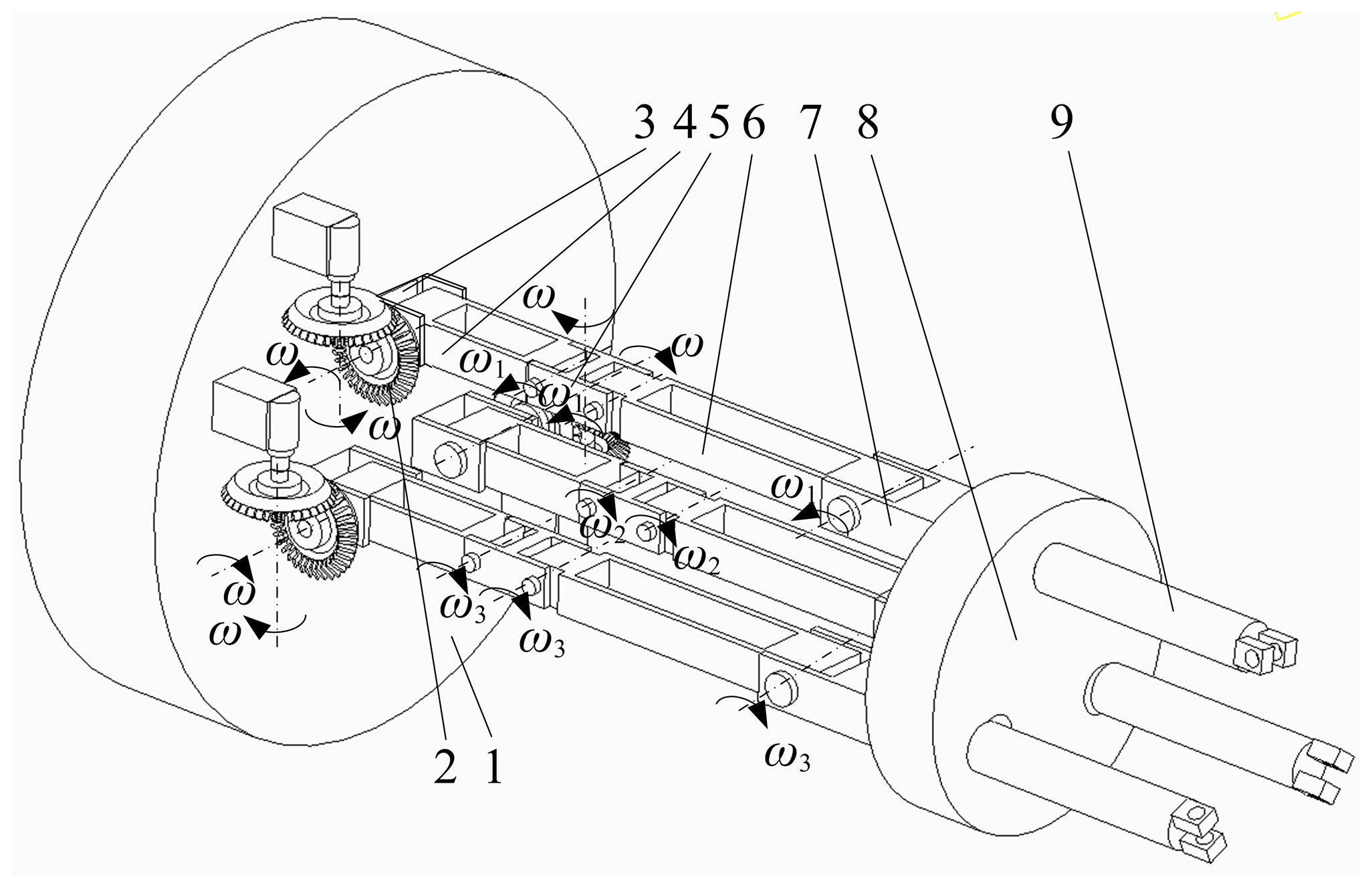
Figure 2Big arm structure diagram of winding robot. (1) Base, (2) bevel gear groups, (3—7) middle rod, (8) moving platform, (9) big arm connecting rod.
During the winding process of the robot, the third middle rod, the forearm connecting rod B, the transfer arm connecting rod, the sixth middle rod and the stopper rotate at an angular speed of ω6; meanwhile the forearm rod A in the big arm drives the rotation with an angular speed ω1. The driving forearm and transfer arm move up together, completing the winding and arranging. Then under the drive of the forearm, the transfer arm that has been winded is pushed into the arranging work station, and at the same time, each part respectively rotates with angular speed ω1, ω2, ω3 and ω4 to close the block with an angular speed ω5. The enameled wire is pushed into the stator turns, and the winding robot completes the winding, arranging and pushing motion.
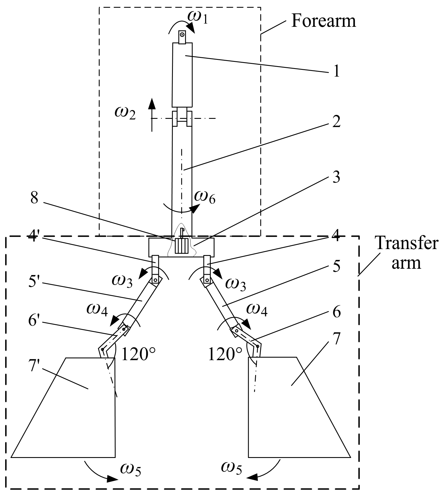
Figure 3Winding robot forearm and transfer arm structure diagram. (1) Forearm connecting rod A, (2–3) middle rod, (4) forearm connecting rod B, (5) transfer arm connecting rod, (6) middle rod, (7) stopper and (8) motor.
In order to ensure that the designed winding robot can achieve the motion posture required for arranging and pushing actions, it is necessary to analyze the motion state of the big arm, forearm and transfer arm (Wang, 2013). Because the winding motion of the transfer arm is directly driven by the motor, this has not been analyzed in this paper.
4.1 Kinematic modeling
The structure of the big arm, forearm and the transfer arm as well as the motion state of each joint was analyzed to determine the motion model of the winding robot as shown in Fig. 3. First, a fixed-coordinate system {xyz} is set up (Chen et al., 2016). x, y and z are the two radial and axial directions of the stator. It can be seen from Fig. 4 that points A, B and C are fixed connection points of the branch chain 3, 2 and 1 to the base (fixed platform) respectively, and points L, M and N are fixed connection points of the branch chain 1, 2 and 3 to the moving platform respectively. The initial direction of all joint coordinates of the big arm, the ABC fixed platform and LMN of the moving platform is the same as the fixed-coordinate system, and ∘. Secondly, according to the design sequence, the base coordinate system of a set of the forearm and manipulator of the winding robot is established. D is the joint of the big arm and forearm, and F and I constitute the forearm–manipulator joint. Due to the radial direction of the stator always being perpendicular to the y axis, the initial working state of the robot is as follows: the angle between the big arm and forearm is ∠LDE=90∘, and the angle between the forearm and manipulator is ∘. The forearm and manipulator of each joint moving coordinate system are determined by the fixed-coordinate system according to the motion state and the right-hand helical rule. In the process of motion, the forearm axis is always 90∘ with a fixed-coordinate system z axis.

4.2 Accompany motion analysis
The existence of accompany motion results in the decrease of working efficiency and accuracy of winding robot (Guo et al., 2018). For this reason, this paper adopts the xyz motion Euler angle to analyze the motion attitude of the moving platform in the motion model shown in Fig. 4 (Xia et al., 2012) and obtains the rotation matrix
In Eq. (1), α (rotation angle on the x axis) and β (rotation angle on the y axis) are the attitude angles of the moving platform during normal operation, and ϕ (rotation angle on the z axis) is the attitude angle of the moving platform during the accompany motion.
In Fig. 4, N, M and L are fixed on the moving platform, and the position vectors in the moving coordinate system {x14y14z14} are
Equation (2) shows the structural parameters of the dynamic platform.
Let the position vectors of N, M and L in fixed-coordinate system {xyz} be .
According to Fig. 4, the vector constraint equation is established.
In Eq. (3), p is the vector from M to B.
Substitute Eqs. (1) and (2) into Eq. (3) and get the expression of the position vector of L, N and M.
In Eq. (3), P is the vector from M to B.
Substitute Eqs. (1) and (2) into Eq. (3) and get the expression of the position vector of L, N and M.
Since the plane of e1 and e2 and the plane of e2 and e3 are at 120∘, the constraint equation is established:
Simplifying Eq. (5), we can obtain
In Eq. (6), , and each value of has nothing to do with rotation about the z axis, so it can be obtained according to Eqs. (4) and (6).
Substitute Q5 and Q8 in Eq. (4) into Eq. (7), and we can get
Because px≠0, and it has nothing to do with ϕ,
According to Eqs. (9) and (10), we can obtain ϕ≠0.
Therefore, the accompany motion exists. For this purpose, the upper arm limit sleeve should be designed to control the accompany motion angle.
4.3 Kinematic analysis
In order to determine that the winding robot can realize the linear motion, the inverse kinematics solution is used to solve the working position change of the parallel platform and the motion state of the forearm in this paper.
Firstly, the rod length and attitude angle of the two branches of e1 and e2 are determined. The e2 as defined in Eq. (4) is known, assuming that the moving coordinate system rotates the attitude angle around the x14 axis to α and then around the y14 axis to β; then the rotation matrix of the moving platform LMN is
The vector constraint equation between e1, e3 and e2 is established in the fixed-coordinate system {xyz}.
In this equation, li and yi are the rod length and unit vector of the AN, BM and CL branch chain.
In Fig. 4, A, B and C are fixed on the fixed platform, and the position vectors in the fixed-coordinate system {xyz} are
In the above equation, yx, yy and yz are the coordinates of the unit vector y2 in the fixed-coordinate system {xyz}.
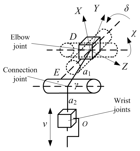
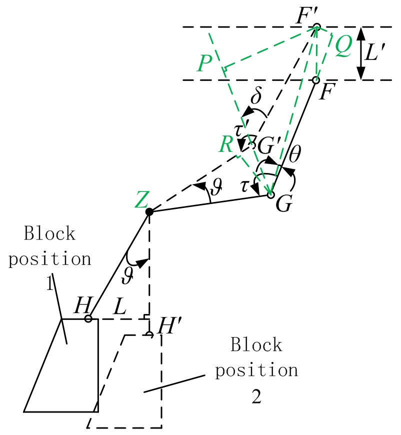

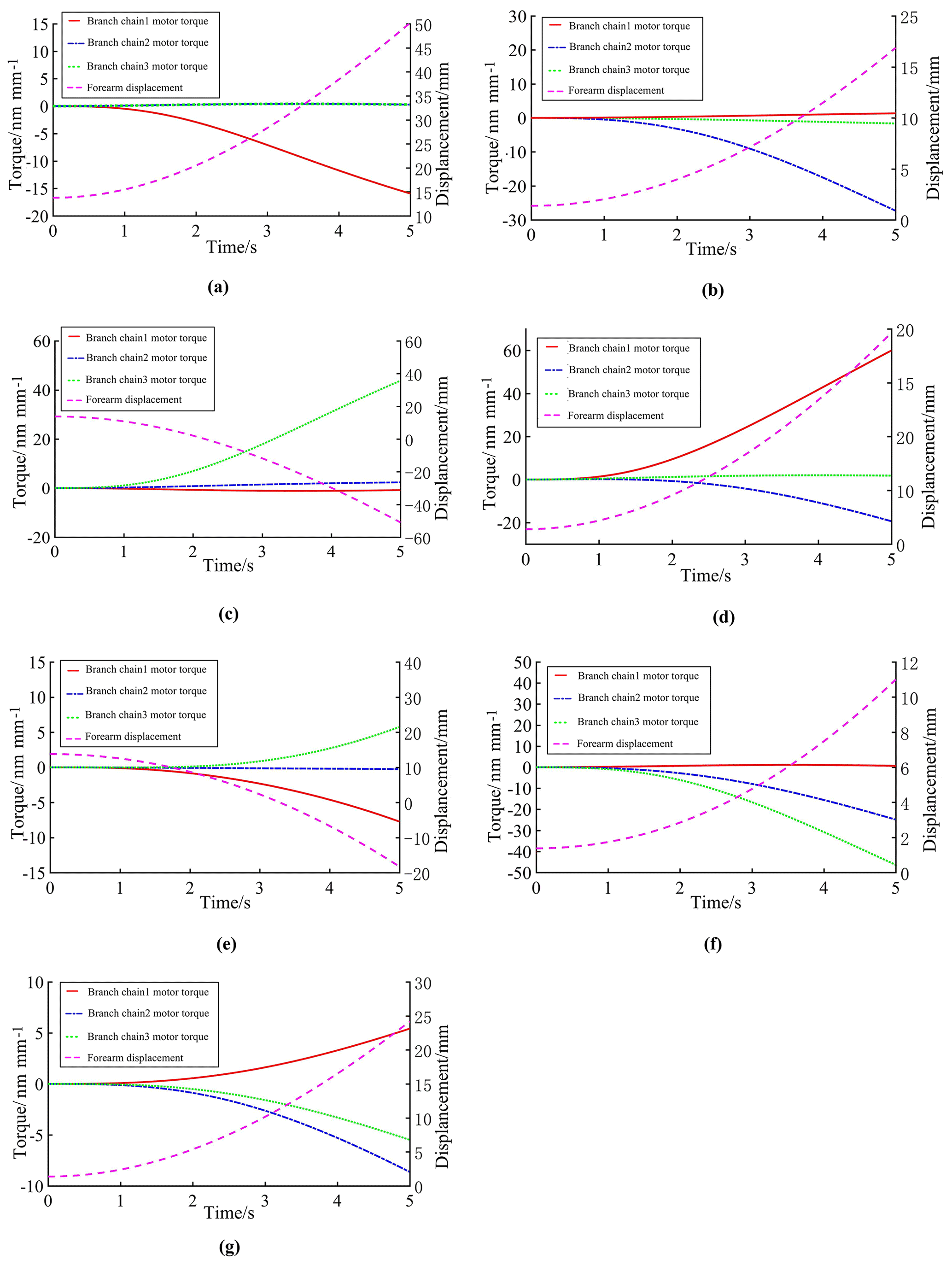
Figure 8Changes of forearm displacement during wiring of winding robot. (a) Simulation results of branch chain 1 as the source power. (b) Simulation results of branch chain 2 as the source power. (c) Simulation results of branch chain 3 as the source power. (d) Simulation results of branch chain 1 and 2 as the source power. (e) Simulation results of branch chain 1 and 3 as the source power. (f) Simulation results of branch chain 2 and 3 as the source power. (g) Simulation results of branch chain 1, 2 and 3 as the source power.
According to Eqs. (2), (11), (12), (13) and (14), the following equation can be obtained:
From Eqs. (15) and (16), it can be seen that the variation of the working position of the parallel platform is determined by the attitude angles α and β, while the variation of the two attitude angles depends on the displacements of the three branch chains.
The motion state of the forearm is related to the parallel platform, and its motion model is shown in Fig. 5.
Point D is taken as the base coordinate point and point O as the end point to establish the coordinate system and to establish the elbow–wrist joint equation by the D–H method.
From Eqs. (17) and (18), the displacement of point O (in Fig. 4) is determined, and then it is determined that the winding robot can realize the line winding action.
In order to determine that the winding robot can realize the line pushing action, it is necessary to establish the motion relationship equation between point O (in Fig. 4) and the closing of the stopper. From Fig. 6, the displacement of point F can be obtained.
In the formula, d1 is the length of the DF rod, and d2 is the length of the ZG rod; ∘, ∘.
From Eq. (19), the relationship between FF′ (wrist joint displacement) and L (stop displacement) is obtained, which confirms that the stopper of the manipulator can move with the wrist joint to ensure that the winding robot can realize the line pushing action.
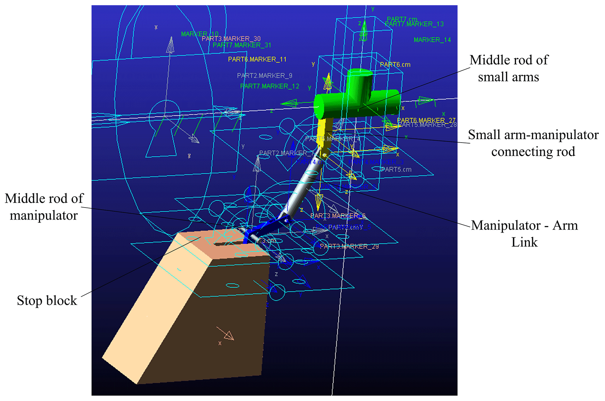
Figure 9Winding robot manipulator model, arm addition constraints and driving force diagram.
5.1 Kinematics simulation of winding robot
5.1.1 Inverse kinematics simulation of winding robot
In order to test the accuracy of the multi-line parallel kinematic model, the established virtual prototype is simulated by ADAMS software. The rotational pair and the moving pair are added to the moving platform separately to limit its partial freedom. After the various parameters and conditions are set, the virtual prototype models of the robot arm and arm are established, and the structure is shown in Fig. 7.
Firstly, the winding robot was simulated in a kinematic way. The branch chain was set as the source power to track the displacement of the forearm and the chock. During the simulation process, the torque of each branch chain motor was used to represent the displacement in the direction of stator axis, the simulation results are shown in Figs. 7 and 8. The motor torque represents the displacement of the branch chain on the xyz axis.
It can be seen from Fig. 8 that each branch chain produces a torque change and the forearm has a displacement, indicating that each branch chain can transmit motion to the forearm through the moving platform, which verifies the correctness of the motion relationship between the moving platform and the forearm in the kinematic analysis. Figure 8g shows that under normal working conditions of the robot (branches 1, 2 and 3 are the source power), the forearm can produce smooth displacement to complete the specified action. From Fig. 8a to f, it can be seen that in special circumstances (a single branch chain or two branch chains stop outputting power), the forearm can still produce displacement, which proves that the robot will not stop in the case of unexpected situations.
5.1.2 Simulation verification of winding robot manipulator block closure
As shown in Fig. 9, according to the actual situation, the moving pair, the rotating pair and the fixed pair are added in turn, and the horizontal constraint between the block and the x axis direction of the basic coordinate system is added. The moving pair of the component where the O point is located is added to drive, and the step length is set to 1000. It is verified that the displacement of the O point along the y axis drives the block to do complete closed motion.
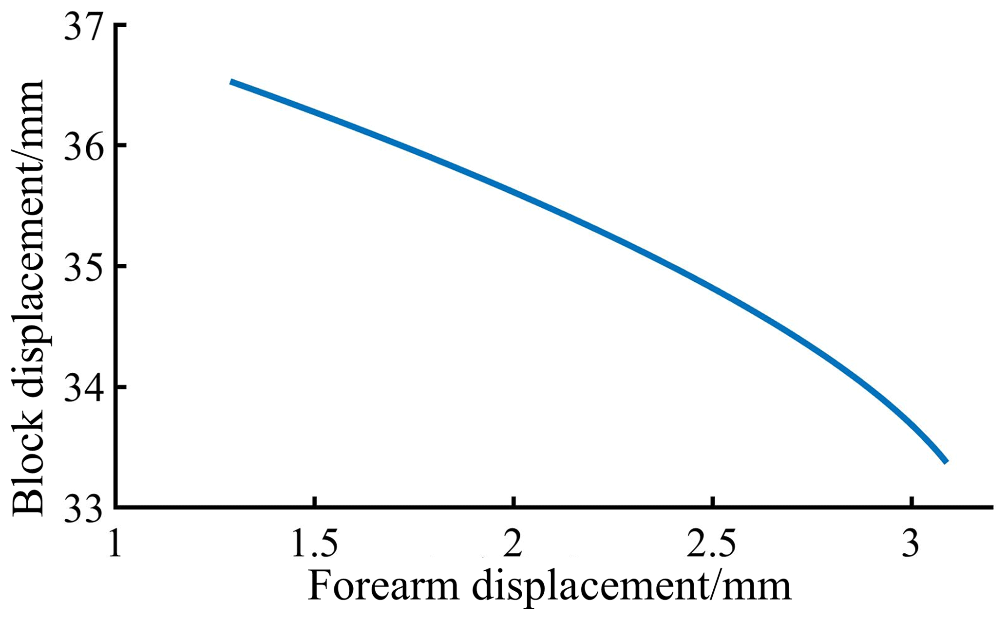
It can be seen from Fig. 10 that when the forearm is displaced, the stopper can be driven to realize the closing movement, so that the manipulator can complete the push line movement. From the slope of the curve, it can be seen that when the forearm displacement is large, the closing rate of the stopper speeds up, the manipulator push line movement efficiency is improved and the correctness of the block closing movement model is verified.

Figure 11Joint configuration diagram.
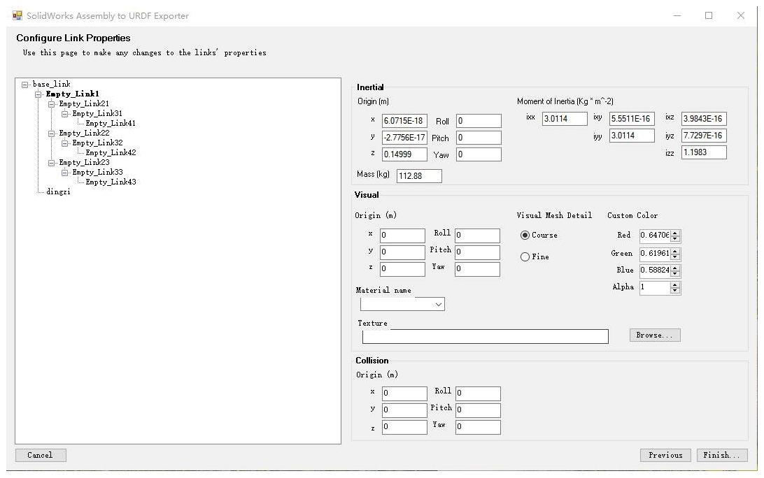
Figure 12Link configuration diagram.
5.2 ROS platform construction and motion planning simulation analysis of winding robot
5.2.1 ROS platform construction of winding robot
The ROS simulation platform of the winding robot is built, and the winding robot model is imported and displayed. The preparation of the robot description file URDF and the analysis of the working framework principle of MoveIt are completed. In the preview interface for each joint, movement restrictions, including torque, speed and movement angle restrictions, are added, as shown in Fig. 11. At the same time, it is necessary to add the rotational inertia information, friction coefficient, collision coefficient and other dynamic characteristics to each link in order to obtain a more realistic physical simulation, as shown in Fig. 12. The three-dimensional model of the robot is shown in Fig. 13, and the robot motion simulation function is realized by the arbotix simulator.
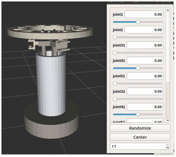
Figure 13Link configuration diagram.
The MoveIt Setup Assistant is used to configure the robot motion planning function package. As shown in Fig. 14, after starting the path planning, you can see the winding robot in the scene configuration and the planning path completing the winding robot ROS platform.
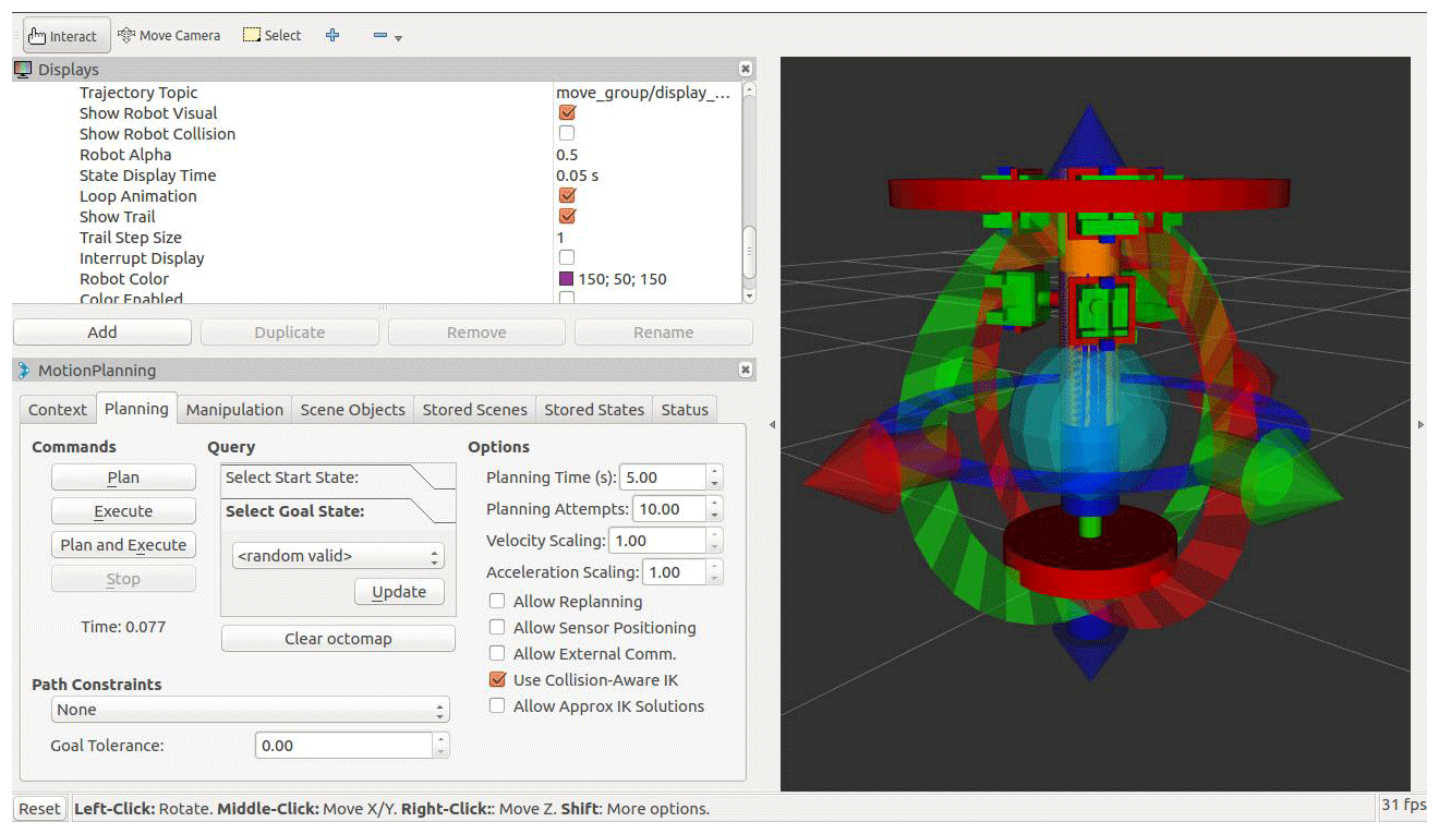
Figure 14Demo file model display.
5.2.2 Motion planning simulation analysis of winding robot
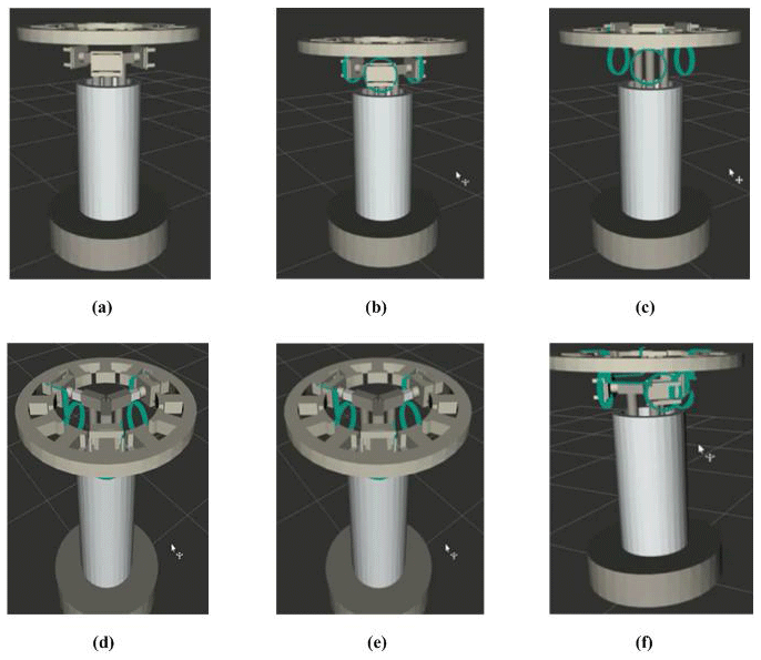
The RRT_Connect algorithm is used to simulate the joint-motion planning of MoveIt and Gazebo for the stator winding robot. As shown in Fig. 15, green is the trajectory generated by the robot winding the enameled wire. From the trajectory in the graph, it can be seen that the winding robot completes a series of processes of winding the enameled wire, arranging the enameled wire on the robot and pushing the enameled wire into the stator coil. As shown in Fig. 16, the robot can perform scheduled winding, arranging and pushing actions on the gazebo physical simulation platform.

Based on the three-phase parallel equivalent winding model, the ROS simulation platform of winding robot is built. The winding robot realizes the action required for multi-wire parallel winding of the stator, and the motion of each part of the robot is not a source of interference. The axis of the moving platform always coincides with the axis of the stator, which verifies the rationality of the structural design and the correctness of the three-phase parallel equivalent winding model.
In this paper, the equivalent model of three-phase parallel multi-wire winding is proposed, and a winding robot with hybrid structure and its kinematics model are designed. By establishing the rotation matrix and vector constraint equation, the relationship between the motion attitude of the moving platform and the displacement of the large arm, the small arm and the wrist is solved, and the influencing factors of the accompanying motion are determined. The winding-line movement of the winding robot is guaranteed. Using inverse kinematics and analytical analysis, the motion model of the arm and the manipulator is established, and the influencing factors of the manipulator are determined, so as to ensure the robot can realize the winding–row–push three-phase parallel multi-wire winding motion. The ROS simulation platform of the winding robot is built to simulate the real working environment, and the motion planning simulation of the winding robot is carried out to realize the winding–row–push three-phase parallel multi-wire winding motion. It shows that the robot can complete multi-wire parallel winding of small motor stators. The research in this paper provides a basis for the multi-wire winding control and intelligent winding methods of robots.
All data included in this study are available upon request from the corresponding author.
EZ and JZ proposed and developed the overall concept of the paper, conducted the mechanism design and simulations and wrote the majority of the paper. YZ and CW supervised and structured the paper. CY helped to make the figures. EZ edited the paper, and JZ helped write the paper.
The authors declare that they have no conflict of interest.
Publisher's note: Copernicus Publications remains neutral with regard to jurisdictional claims in published maps and institutional affiliations.
The authors would like to express their thanks for the support of the Open Research Project of the State Key Laboratory of Robotics and Systems of China (grant no. SKLRS-2017-KF-17).
This research has been supported by the Open Research Project of the State Key Laboratory of Robotics and Systems of China (grant no. SKLRS-2017-KF-17).
This paper was edited by Guowu Wei and reviewed by two anonymous referees.
Chen, D.-S., Zhang, Z.-Q., and Chen, K.-W.: Dynamic model and performance analysis of landing buffer for bionic locust mechanism, Acta Mech. Sinica, 32, 209–223, https://doi.org/10.1007/s10409-015-0523-5, 2016.
Dodds, S.: A Novel Approach to Robust Motion Control of Electrical Drives with Model order Uncertainty, Recent Pat. Electr. Electron. Eng., 3, 3–10, 2011.
Gao, Y., Zhao, W., Qu, K., Li, H., Shao, H., Wang, Q., and Huang, S.: Design of equivalent coils for anti-interference testing of heavy current transformers, Int. J. Appl. Electrom., 56, 211–223, https://doi.org/10.3233/JAE-170052, 2018.
Guo, W., Zhou, Y.-H., Zhang, W.-C., and Zhao, Q.: Hydrodynamic analysis and power conversion for point absorber WEC with two degrees of freedom using CFD, China Ocean Eng., 32, 718–729, https://doi.org/10.1007/s13344-018-0073-2, 2018.
Hao, H., Fei, W., Miao, D., Jin, M., and Shen, J.: Torque characteristics in a large permanent magnet synchronous generator with stator radial ventilating air ducts, Front. Inform. Tech. EL, 17, 814–824, https://doi.org/10.1631/FITEE.1500238, 2016.
He, X., Shi, Y., and Xu, W.: Tension power amplifiers of tape winding machine based on CPLD, 6, Modern manufacturing engineering, China, 2009.
Krim, S., Gdaim, S., Mtibaa, A., and Mimouni, M.: Contribution of the FPGAs for complex control algorithms: sensorless DTFC with an EKF of an induction motor, International Journal of Automation and Computing, 16, 226–237, https://doi.org/10.1007/s11633-016-1017-z, 2019.
Liang, Y., Bian, X., Honghao, Y. U., Liu, X., and Cangxue, L. I. J.: Analysis and Calculation on Circulating Current Losses in Stator Windings With Multiple Bars per Layer of Deficient Transposition, Chinese J. Electron., 33, 168–174, 2013.
Nikonov, A. I., Dikovskii, V. A., Grankin, G. A., and Bobrov, I. F.: Type NvS23A Winding Machine with Electromechanical Placement of Wire, Proceedings of the CSEE, China, 1986.
Qian, Y., Yuan, J., and Wan, W.: Improved trajectory planning method for space robot-system with collision prediction, J. Intell. Robot Syst., 99, 289–302, https://doi.org/10.1007/s10846-019-01113-y, 2020.
Wang, X., Jun, X., and Wen, L.: Winding pattern design and simulation of S-elbow, Chinese J. Aeronaut., 23, 573–577, https://doi.org/10.1016/S1000-9361(09)60256-9, 2010.
Wang, Y. Q.: Path Planning of the Intersecting Line of Cylindrical Pipes Welded by the Welding Robot, Appl. Mech. Mater., 456, 43–49, https://doi.org/10.4028/www.scientific.net/AMM.456.43, 2013.
Xia, X., Han, D., Liu, H. J. M., and Vehicles, S.: Discussion on the Transformation Between Attitude Quaternion and Euler Angles in Large-angle Maneuver Scenario, Missile and space delivery technology, China, 2012.
Zhu, G., Cheng, A., Wang, Z., and Lei, F.: Analysis of lightweight composite body structure for electrical vehicle using the multiscale approach, Chin. J. Mech. Eng.-En., 52, 145–152, https://doi.org/10.3901/JME.2016.06.145, 2016.
- Abstract
- Introduction
- Three-phase parallel equivalent winding model is established
- Winding robot structure design
- Moving analysis of winding robot
- Kinematics simulation and experimental study of winding robot
- Conclusion
- Data availability
- Author contributions
- Competing interests
- Disclaimer
- Acknowledgements
- Financial support
- Review statement
- References