the Creative Commons Attribution 4.0 License.
the Creative Commons Attribution 4.0 License.
 | 06 Nov 2019
The nonlinear vibrations of a vertical hard gyroscopic rotor with nonlinear characteristics
Zharilkassin Iskakov
Kuatbay Bissembayev
The paper considers an impact of viscous linear and cubic nonlinear damping of the elastic support on nonlinear vibrations of a vertical hard gyroscopic unbalanced rotor, taking into account nonlinear stiffness of the support material. Analyzing the research results shows that linear and cubic nonlinear damping can significantly suppress the resonance peak of the fundamental harmonic, eliminate the jumping phenomena of the nonlinear system. In non-resonance areas where the velocity is higher than the critical one, cubic nonlinear damping, unlike linear one, can slightly suppress amplitude of the rotor vibration. Therefore, in the high-velocity area, only nonlinear damping can maintain performance of a vibration isolator. In resonance area, an increase in linear or cubic nonlinear damping significantly suppresses the ability to absolute displacement. In non-resonance area, where the rotational velocity is lower than the critical one, they have almost no impact on ability to absolute displacement. In high velocity area, an increase in nonlinear damping may slightly increase the moment of force transmissibility, but linear damping has almost no impact on it. The obtained results can be successfully used to produce passive vibration isolators used for damping the vibrations of rotary machines, including gyroscopic ones.
- Article
(1743 KB) - Full-text XML
- BibTeX
- EndNote


As you know, the rotary machines are widely used in many industries and have been studied for a long time. Despite this, there are many problems unsolved, in particular those associated with an action of mass imbalance on vibrations and stability, and subsequently with the stabilization of resonance vibrations of the rotary machines.
A simplified model with concentrated rotor system parameters is typically used to study the dynamics of a single rotor shaft on the bearing supports. It is very important to use the properties and characteristics of the support material for vibration attenuation and damping to stabilize a movement of the unbalanced rotor and the vibration systems. Supports are the mean for connecting devices between the rotor and the supporting structure, which have various shapes and designs depending on the specific assumptions. A convenient way is to introduce attenuation for supporting the bearings in the rotor system on viscoelastic flexible rubber supports (Zakaria et al., 2015). In parallel with the development of viscoelastic material simulation (Gil-Negrete et al., 2009; Richards and Singh, 1999), which helps to describe a complexity of material properties, the use of viscoelastic components in rotor dynamics and vibration systems (Ravindra and Mallik, 1994; Peng et al., 2012; Ho et al., 2012) as a whole also increased, including with nonlinear elastic characteristics and damping. For example, Ravindra and Mallick (1994) researched the parametric impact of different types of attenuation on the performance of nonlinear vibration isolators in case of harmonic excitation. The paper (Peng et al., 2012) considers an efficiency of passive vibration isolators with linear damping and cubic nonlinear damping in resonance and non-resonance vibration areas of the system with linear stiffness. It also provides an excellent overview of researches of the linear and nonlinear vibration isolation systems. In the paper (Ho et al., 2012), an impact of cubic nonlinear rigidity of the material on the performance of the isolator is additionally taken into account in the studies. The papers (Iskakov, 2015, 2017a, b) researched impacts of quadratic nonlinear damping on the resonance vibrations and stability of the vertical gyroscopic unbalanced rotor with quadratic and cubic nonlinear stiffness of an elastic support. Magnetorheological materials can be used as damping elements. The model is based on presentation of magnetorheological oil by bilinear material (Zapomel and Ferfecki, 2015). In the paper (Fujiwara et al., 2015), an experimental single-disc rotor system is prepared that is supported by ball bearings at both ends, and vibration is compared with a flexible support containing springs or rubber blankets and with a rigid support base, through simulation and experiment.
This paper is aimed at researching an impact of the material of the elastic bearing support with linear and cubic nonlinear damping on the main resonance curve and the moment of force transmissibility of the gyroscopic vertical hard unbalanced rotor, taking into account the nonlinear stiffness of the support.
The rotor flowchart shown in Fig. 1 is considered. Shaft with the length L is installed vertically, using a lower hinged and an upper elastic support at a distance l0 from it. A disc having a mass m, a polar moment of inertia IP and a transverse moment of inertia IT, being the same for any direction, is fixed at the free end of the shaft. The shaft speed ω is so high that the rotor can be considered as a gyroscope, which fixed point is the lower shaft support. The geometric center of the rotor S is determined by the Cartesian coordinates x and y. At this time, the shaft deflections are determined by the angular coordinates θx and θy. The Cartesian and angular coordinates of the geometric center S are related by the relations x=Lθx and y=Lθy. The rotor movement towards the coordinate axis z is neglected. Next, we denote the coordinates of the center of masses m of the disc through xm and ym.
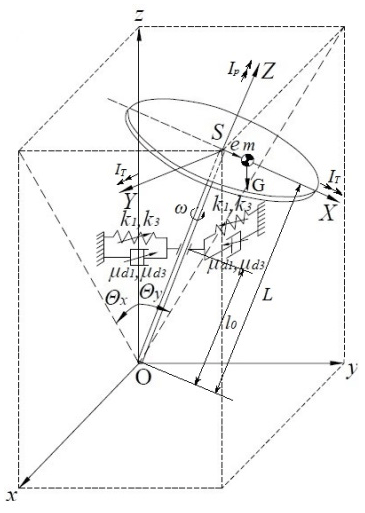
Also assume that linear eccentricity e lies on the X-axis of the SXYZ coordinate system which rotates with the rotor. Limit its elves to small deviations of the rotor axis, so will take into account in the calculations only terms that are linear with respect to small quantities e, θx, θy, xm, ym.
Given the above, the projections of the angular velocity on the coordinate axes will be written as
and kinetic energy of the system as
given that , Iz=IP and Eq. (1), obtain in a form of
where
Moments of external forces are as follows
where L is the shaft length, G=mg is the disc weight.
Mallick et al. (1999) experimentally confirmed that the restoring and damping forces in elastomeric isolators should be described, using a nonlinear model. Richards and Singh (1999) found that rubber dampers have both nonlinear damping and nonlinear stiffness. To achieve higher performance, any nonlinearities in the design should be taken into account. Consequently, the elastic support of the upper bearing of the gyroscopic rotor can be made of non-linear materials, such as rubber, resin and other polymers widely used as the damper of the arising vibrations. Given all this, we set the dissipative forces in the elastic support as
where μd1 is a coefficient of linear viscous damping of the support material, μd3 is a coefficient of nonlinear cubic viscous damping of the support material. If consider that the rotor shaft is hard and only its upper support has elasticity, the potential energy of the system can be represented as
where k1 is a coefficient of linear stiffness of the elastic support, k3 is a coefficient of nonlinear stiffness of the elastic support.
The Lagrange's Equations of Second Kind (Yablonsky, 2007) for the rotor system are written as
Here, qi:θx, θy is the joint coordinates; Qi:Mx, My are the generalized forces.
Substituting the expressions (2)–(6) in (7), obtain the equations of motion of the rotor
where
is an amplitude of the resultant moment of the external forces.
By entering the following dimensionless parameters
where
is a critical velocity of a damping-free linear system, using a designation of the expression of the dimensionless amplitude of the resultant moment of external forces
can provide the equations of motion (8) with a compact dimensionless view
Here the strokes denote derivatives in dimensionless time .
Thus, it turns out that the steady-state motion of the considered rotor is described by the Duffing type differential equation system (13) and (14). To determine a periodic solution with a period equal to the period of external action, a method of decomposition of solutions (13) and (14) into Fourier series with uncertain coefficients is usually used. The coefficients can be found by the harmonic balance method (Hayashi, 1964; Szemplinska-Stupnicka, 1968; Kydyrbekuly, 2006), taking into account the finite and usually small number of terms.
Expanding the solutions of the equations of motion (13) and (14) into the Fourier series with indefinite coefficients, can verify that the approximation of the solutions with a simple harmonic and oscillation frequency equal to the disturbing moment frequency is quite satisfactory in the case of the main resonance. Taking into account the following notation of the vibration parameters A=A1 and α=α1, the solutions of the equations of motio (13) and (14) at a first approximation can be written as
After substitution the expressions (15)–(16) in (13)–(14) and applying the harmonic balance method (Hayashi, 1964; Szemplinska-Stupnicka, 1968; Kydyrbekuly, 2006), obtain the amplitude-frequency and the phase- frequency dependences of the fundamental harmonic
where is the nominal thickness of the disc.
The formula for the amplitude-frequency characteristic (17) taking into account the expressions of dimensionless parameters (10), the critical velocity formula (11), and the formula for the resulting moment amplitude (12), may be needed when experimentally determining the values of the linear damping coefficients μ1 and nonlinear cubic damping μ3 of the support under the values of the amplitude A and rotation speeds Ω of the experimental resonance curve A=A(Ω).
The results of numerical solutions of the equations of motion (13) and (14) of a rotor system with nonlinear rigidity and the dependency graphs (15) and (16) taking into account expressions (17) and (18) are presented in Figures 2 and 3 for the following parameters: l=0.88, P=0.012, , H=0.09, ε=0.91, K1=1.19, Ω=1.5.
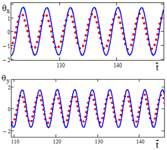
Figure 2Oscillogram θx=θx(t) and θy=θy(t) when . Solid lines are the results of a numerical solution, points are the results of an analytical solution.
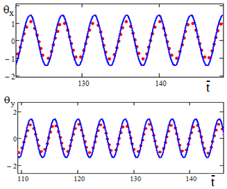
Figure 3Oscillogram θx=θx(t) and θy=θy(t) when . Solid lines are the results of a numerical solution, points are the results of an analytical solution.
The graphs in Figs. 2 and 3 show a sufficient approximation of the results of numerical modeling and analytically obtained results.
In the absence of nonlinear terms in Eqs. (13) and (14), the results for the linear rotor model are obtained from expressions (17) and (18) (Iskakov and Kalybaeva, 2010).
With the introduction of additional value notations
obtain an expression for the amplitude-frequency and the phase-frequency characteristics
where the notations are introduced
Amplitude-frequency supporting curves typically describe a relationship between amplitude and frequency of free vibrations of the system without damping (Panovko, 1971). Assuming the expression M to be equal to zero due to the external moment, and the damping coefficients μ1 and μ3 in Eq. (20), obtain the equation of the supporting curve for vibrations at the fundamental resonance frequency
Here
It can be seen from formula (23) that the supporting curve is a parabola symmetric about the axis Ω, the larger the valueK3 the greater the slope to the right, of the supporting curve Formula (23) and the reference curve constructed from it are important for the experimental determination of the nonlinear stiffness coefficient of the support material K3 from the intersection point of the reference curve with the resonance curve A=A(Ω).
In case when H=0.99 and moment P of gravitational force is neglected the amplitude of the centrifugal couple is M=Ω2. Solving Eq. (20) with respect to A depending on Ω and μ1 at a constant value of μ3= 0 and depending on Ω and μ3 at a constant value of μ1= 0 with K3=0, get
where
If shaft speeds are close to zero, the action of the gravitation moment is more noticeable. Then, if Ω=0, the Eq. (20) takes the following form
Solutions of Eq. (26) if K3=0:
and if K3≠0
Using dimensionless parameters in accordance with formulas (10), it is possible to give the following form to expressions of the projections of moment of transmitted force (transmissive force)
On the other hand, take the projection of the moment of transmitted force (29) in a form of the following harmonics
Substituting solutions (15), (16) and (30) into expressions (29) and taking into account additional notations of values (19), obtain an expression for determining amplitude of the moment of transmitted force Aτ depending on the rotation velocity Ω, the linear damping coefficient μ1, and the nonlinear damping coefficient μ3:
The moment of force transmissibility is defined as a ratio of amplitude of the moment of transmitted force to the amplitude of the disturbing moment (Ho et al., 2012):
Introduce a function
Calculate a derivative of f at Ω and equate it to zero:
The solution of Eq. (34) is a certain value Ω1. If K3=0, this value is equal Ω1≈1. It can be shown that the second derivative of f at Ω at this point is negative, i.e. the function f(Ω) really has the maximum value, while
If the shaft speed is Ω=0 and K3=0 the moment of force transmissibility of the system is
and if Ω=0 and K3≠0
The numerical solution of the Eq. (20) and the calculation from the expression (32) were performed using MathLab to demonstrate an impact of linear and nonlinear viscous damping on vibration isolation of the Duffing type rotor system. The results are shown in Figs. 4–13. The rotary system with linear stiffness of the elastic support as described in researches (Peng et al., 2012; Iskakov, 2018a, b) is presented in Figs. 4–7. In Figures 4 and 5, the elastic support of the rotor has linear stiffness and linear damping with μ1=0.1, 0.2, 0.4. When the parameter of linear damping μ1 increases, the amplitude of vibrations A and the moment of force transmissibility of the system γ in the resonance area near Ω≈1 decrease, and in non-resonance areas, where Ω≻1 or Ω≺1, the impacts of μ1 on A and γ are very weak and negligible. In Figs. 6 and 7, the μ1 value is kept constant at the level of 0.1, while the cubic damping parameter μ3 takes 0, 0.2, 0.4. In this case, the resonance peak of the fundamental harmonic at Ω≈1 is significantly suppressed with increasing μ3, and in the non-resonance area, where Ω≺1 μ3 has virtually no impact on A and γ. However, in the non-resonance area, where Ω≻1, it can be seen that an increase in μ3 may slightly suppress the A vibration amplitude and slightly increase γ.
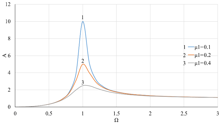
Figure 4Dependence of the vibration amplitude A on the rotor velocity Ω with linear stiffness of the support and at different values of the coefficient of linear viscous damping μ1.
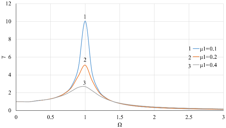
Figure 5Dependence of the moment of force transmissibility of the system γ on the rotor velocity Ω with linear stiffness of the support and at different values of the coefficient of linear viscous damping μ1.
Figures 8–9 shows the effects of linear damping in case of nonlinear stiffness of the elastic support. A contrast between the effects of linear and nonlinear viscous damping can be observed by comparing Figs. 8–9 with Figs. 10–13, where the cubic viscous damping coefficient μ3 is 0, 0.2, 0.4 for K3=0.05 and K3=0.1, respectively. Similar to the case of pure linear stiffness, the linear viscous damping μ1 again modifies the resonance area without causing noticeable effects in non-resonance areas.
To ensure the stable movement, avoiding jumping should be an important feature of the vibration isolator. Researches of Ravindra and Mallick (1994) have shown that the jumping phenomena can be eliminated by linear damping. With pure linear viscous damping, the calculation results in Figs. 8 and 9 show jumps occurring at Ω=1.54 and Ω=1.52 when μ1=0.1 and μ1=0.2 for K3=0.1 and μ3=0, but when the level of linear damping increases to μ1=0.4, jumps no longer exist. Nonlinear viscous damping can also take into account the known jumping phenomenon in the presence of nonlinear stiffness of the elastic support of the rotor. In Figs. 10–13, jumps disappear when μ3 increases from 0 to 0.2. A compromise between the use of linear damping to eliminate the jumping phenomena is in the overwhelming impact of nonlinear damping on the vibration amplitude in high velocity areas.
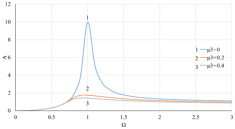
Figure 6Dependence of the vibration amplitude A on the rotor velocity Ω with linear stiffness of the support and at value of the coefficient of linear viscous damping μ1=0.1 and various values of nonlinear viscous damping coefficient μ3.
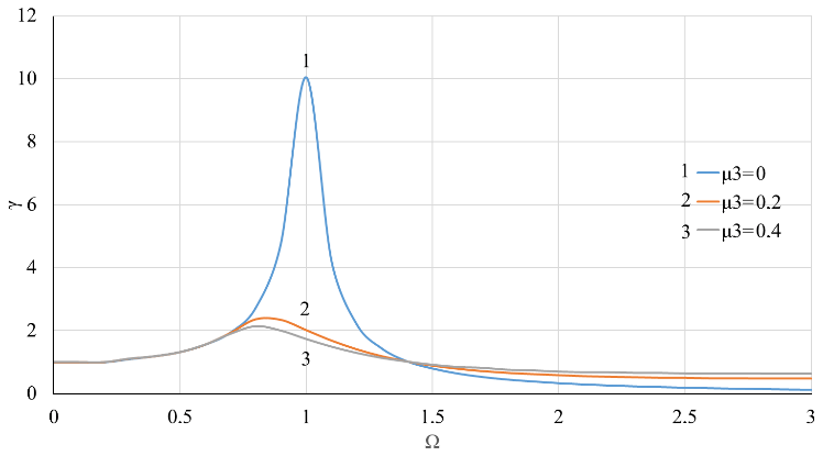
Figure 7Dependence of the moment of force transmissibility of the system γ on the rotor velocity Ω with linear stiffness of the support and at value of the coefficient of linear viscous damping μ1=0.1 and various values of nonlinear viscous damping coefficient μ3.

Figure 8Dependence of the vibration amplitude A on the rotor velocity Ω with nonlinear stiffness coefficient of the support K3=0.1 and at different values of the coefficient of linear viscous damping μ1.
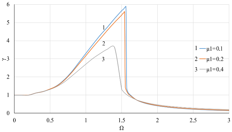
Figure 9Dependence of the moment of force transmissibility of the system γ on the rotor velocity Ω with nonlinear stiffness of the support K3=0.1 and at different values of the coefficient of linear viscous damping μ1.
In non-resonance area, where Ω≺1, linear damping μ1 and cubic nonlinear damping μ3 have virtually no impact on the ability to the isolator absolute displacement. Derivatives and moment of force transferability of the system γ weakly depends on μ1 and μ3. In the resonance area, where Ω≈1, an increase in either linear damping μ1 or cubic nonlinear damping μ3 can significantly suppress ability to absolute displacement. Derivatives and , with an increase in μ1 and μ3, the moment of force transmissibility of the system γ decreases. In high velocity area of, where Ω≻1, an increase in the linear damping μ1 does not affect the ability to the isolator absolute displacement. Derivative the moment of force transmissibility of the system γ remains almost unchanged, an increase in the cubic nonlinear damping μ3 may slightly reduce the ability to relative displacement and an increase in ability to absolute displacement and the moment of force transmissibility of the system γ, i.e .

Figure 10Dependence of the vibration amplitude A on the rotor velocity Ω with nonlinear stiffness coefficient of the support K3=0.05 and at value of the coefficient of linear viscous damping μ1=0.1 and various values of nonlinear viscous damping coefficient μ3.
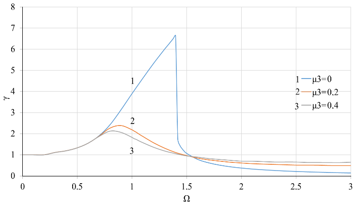
Figure 11Dependence of the moment of force transmissibility of the system γ on the rotor velocity Ω with nonlinear stiffness coefficient of the support K3=0.05 at value of the coefficient of linear viscous damping μ1=0.1 and various values of nonlinear viscous damping coefficient μ3.
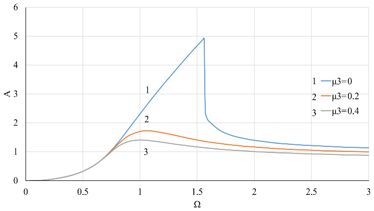
Figure 12Dependence of the vibration amplitude A on the rotor velocity Ω with nonlinear stiffness coefficient of the support K3=0.1 at value of the coefficient of linear viscous damping μ1=0.1 and various values of nonlinear viscous damping coefficient μ3.
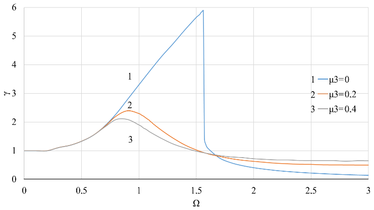
Figure 13Dependence of the moment of force transmissibility of the system γ on the rotor velocity Ω with nonlinear stiffness coefficient of the support K3=0.1 at value of the coefficient of linear viscous damping μ1=0.1 and various values of nonlinear viscous damping coefficient μ3.
Diagrams for study of the phase-frequency characteristic of the rotor are shown in Figs. 14–17. When plotting the diagrams, the properties of the arctangent function were used. These diagrams show that in case of linear stiffness of the support, a rotation of the vibration phase occurs when passing through the critical velocity, i.e. when Ω=1 (Figs. 14–17), and in case of a nonlinear component of stiffness of the support, a rotation of the vibration phase is observed in a phenomenon of the amplitude jump, in Figs. 16–17 this corresponds to the shaft velocity Ω=1.6. The joint impact of the linear and nonlinear components of the support damping essentially eliminates the jump phenomenon, which indicates the rotation of the vibration phase when the shaft velocity is close to the critical one, i.e. if Ω≈1 (Fig. 17), as in the case of only linear stiffness of the support (Figs. 14–15).
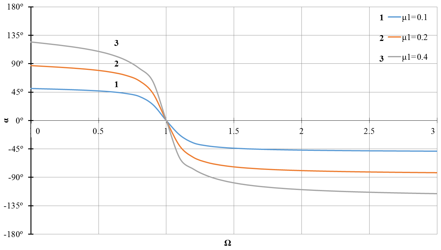
Figure 14Dependence of the vibration phase α on the rotor speed Ω with linear stiffness of the support and at different values of the coefficient of linear viscous damping μ1.

Figure 15Dependence of the vibration phase α on the rotor speed Ω with linear stiffness of the support and at value of the coefficient of linear viscous damping μ1=0.1 and different values of the nonlinear viscous damping coefficient μ3.
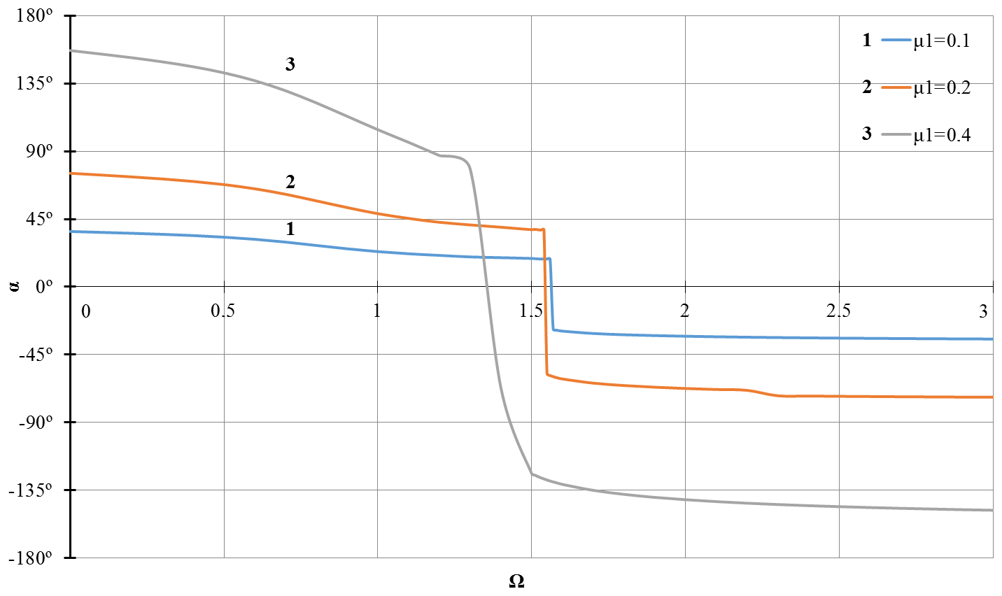
Figure 16Dependence of the vibration phase α on the rotor speed Ω with coefficient of non-linear stiffness of the support K3=0.1 and at different values of the coefficient of linear viscous damping μ1.
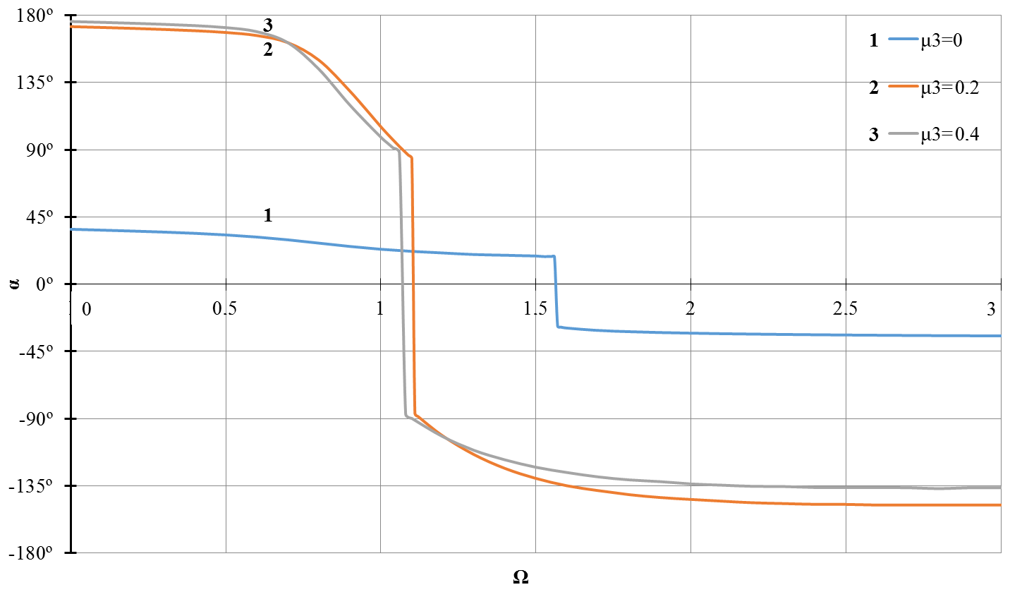
Figure 17Dependence of the vibration phase α on the rotor speed Ω with coefficient of non-linear stiffness of the support K3=0.1 and at value of the coefficient of linear viscous damping μ1=0.1 and different values of the nonlinear viscous damping coefficient μ3.
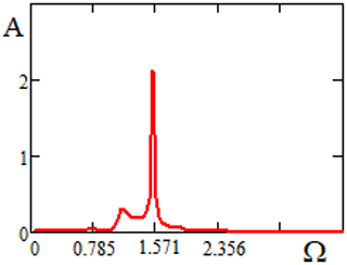
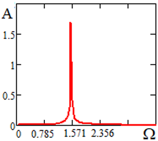
The results of numerical solutions of the equations of motio (13) and (14) of a rotor system with nonlinear rigidity with the output of the A=A(Ω) dependence for the parameters: l=0.88, P=0.012, , , H=0.09, ε=0.91, K1=1.19 are shown in Figs. 18 and 19. A comparison of the graphs in Figs. 18 and 19 shows that nonlinear damping of the elastic support significantly suppresses the main resonant amplitude at Ω≈1.57 and completely eliminates the height of the vibration amplitude in the region of the rotation speed Ω∼1.178.
Consider motion stability using an approximate theory (Iskakov, 2018b; Iskakov, 2019; Van Dooren, 1971). The geometric location of the points at which the amplitude curves for the oscillations of the principal resonance have vertical tangents is determined by the equation
In accordance with Eq. (20), equality takes place
Differentiated the last Eq. (39) in frequency, obtaining
It follows that
Condition (36) is approximately satisfied subject to the equality
Equality (42) with allowance for (39) leads to the equation
Equation (43) describes the boundary curves of the stability region for oscillations at the principal resonance frequency. Therefore, the geometrical location of the points at which the amplitude curves have vertical tangents determine the boundaries of the stability region (Iskakov, 2018b, 2019; Van Dooren, 1971).
The solutions of Eq. (43) have the form
Equation (43) have real roots (44) under the condition
where
The results of calculations by the formula (44) for a rotor system with the support of cubic non-linear stiffness under the influence of linear and non-linear damping of the support are shown in Figs. 20 to 21. Figure 20 were given the boundaries of the instability region of an oscillatory system with non-linear stiffness K3=0.2 depending on the rotation velocity Ω for different values of the linear damping coefficient μ1=0.1; 0.2; 0.4. A slight narrowing of the height of the instability region is observed as the linear damping coefficient increases from 0.1 to 0.4.
Figure 21 shows the boundaries of the instability region of an oscillatory system with non-linear stiffness K3=0.2 depending on the rotation velocity Ω for different values of the non-linear damping coefficient μ3=0; 0.01; 0.02. Here it was take that μ1=0.1. This shows that with an increase the coefficient of nonlinear damping μ3 from 0 to 0.02, not only the height of the instability region decreases, but also its width.
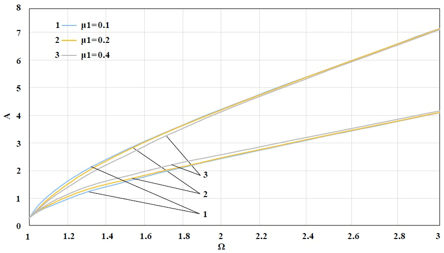
Figure 20The boundaries of the instability region for a system with a coefficient of non-linear stiffness of the support K3=0.2 and different values of linear viscous damping coefficient μ1.
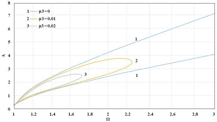
Figure 21The boundaries of the instability region for a system with a coefficient of non-linear stiffness of the support K3=0.2 with a linear viscous damping coefficient μ1=0.1 and different values of non-linear viscous damping coefficient μ3.
Experimental studies of an effect of the support material on dynamics of the centrifugal gyroscopic rotor were carried out on a test unit which is generally shown in Fig. 22, and a flow chart with all measuring instruments is shown in Fig. 23.
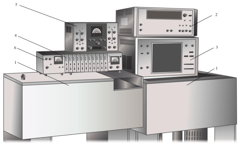
Figure 22Test Unit Overview: 1 – centrifuge with rotor, 2 – F 5034 frequency meter, 3 – H 043.1 electromagnetic oscillograph, 4 – Topaz-3 DC amplifier, 5 – amplifier UT-4 AC amplifier, 6 – Agate power supply.

The unit consists of an electrically powered rotor, a channel for measuring and recording the precession motion performance, a channel for measuring and recording the rotor shaft speed, a channel for measuring and recording current in driven electric motor.
The rotor to be studied is made in form of a cylindrical cup made of duralumin D 16 T with a top transparent PMMA cover. Distance between supports l0=0.33 m, distance from the bottom support to the cup center L=0.52 m, eccentricity m, cup mass m=3 kg, cup weight G=29.4 N, the rubber support rigidity coefficient N m−1. The rotor is mounted on the upper cone part of the shaft inside the centrifuge (1).
The unit uses an electromagnetic speed sensor, voltage pulses from which are fed to an input of frequency meter F 5034 (2) and/or to one of the channels of the electromagnetic oscillograph H 043.1 (3).
Strain-gauge and variable inductance transducers of displacement were used to record precession motion performance. Transducers are coupled by a half-bridge circuit and are connected to an input of Topaz-3 (4) amplifier. Offset voltage of the bridge between a movable rotor and variable inductance transducer of displacement is fed to the input of UT-4 (5) amplifier and from its output to H 043.1 (3) oscilloscope. Supply voltage of Topaz-3 and UT-4 is produced by Agate (6) power supply unit.
To measure current intensity in circuit of the driving motor, compensation method was used since the capacity variations to be determined are much less than the primary engine capacity.
Dynamic performance of the rotor motion and parameters of interaction with the driving motor were read according to the following procedure.
According to the results of measuring the amplitude of signals received in H 043.1 (3) oscilloscope, from the strain resistor and inductive sensors through Topaz-3 (4) and UT-4 amplifiers (5), respectively, and according to the readings of F 5034 (2) frequency meter, the amplitude-frequency performance of oscillations of the experimental rotor was read.
Sensitivity and stability of amplifier channels was monitored and precession performance was recorded before and after each experiment by displacing the rotor shaft from an equilibrium position towards the sensor using a pusher with a distance meter. Value of voltage applied to the motor from LATR-1M laboratory autotransformer was recorded at all shaft velocities.
Along with determination of the rotor oscillation amplitude and the shaft velocity, the current in the circuit of the motor was recorded by H 043.1 oscilloscope.
The above operations were repeated at different damping of upper elastic support and values of radial clearance of bearing. Changing in damping was achieved by installing the PTFE support material in one case, and the soft rubber support material in another one. Changing in radial clearance was carried out by changing the bearings. Dynamic values of the rotor motion were compared for two limiting options of these parameters – a fluoroplastic support and bearings with 0.1 mm clearance in one case and a soft rubber elastic support and bearings with 0.01 mm clearance in another one.
As can be seen from the above, the measured values were amplitude and frequency of the rotor precession, shaft speed, voltage and current in the driving motor circuit.
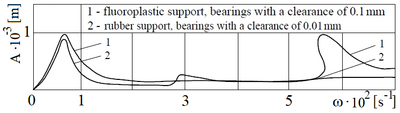
Figure 24Amplitude-frequency characteristic of the centrifugal rotor in different versions of the support material.
Amplitude-frequency characteristics of the rotor measured for cases of fluoroplastic support, bearings with a clearance of 0.1 mm and a rubber support, bearings with a clearance of 0.01 mm are shown in Fig. 24. Similar curves were previously obtained respectively in the papers by Kelzon and Pryadilov (1965), Tuleshov (1987). Comparison of the amplitude-frequency characteristic curves shows that the replacement of the fluoroplastic material of the support with rubber damps a resonance curve of the main harmonic in the area of the critical velocity ω≈68 s−1 and in the high-velocity area up to the rotation velocity ω=284 s−1, completely suppresses a significant elevation of the vibration amplitude in the area of the rotation velocity ω∼600 s−1. It describes a previously undetected peak of much smaller amplitude (relative to the above one) in the area of the rotation velocity of ω∼300 s−1.
Zones of higher vibration amplitudes are not related to a coincidence of the shaft velocity with one of the rotor eigenfrequencies, but are related to the ripple frequency of power in the electric motor because of the limited energy source power. The presence of modes of coupled vibrations of power and precession amplitude (Felix et al., 2015; Tuleshov, 1987), at frequencies that are multiples of the frequency of the alternating component of the actuating moment (628 s−1) can be, along with the nonlinearity of the system itself, also due to the presence of subharmonics in the time law of the supply voltage change. The results of the experimental works qualitatively correspond to the results of theoretical studies of the impact of nonlinear damping on the amplitude-frequency characteristic of the rotor, carried out in the absence of nonlinear stiffness of the elastic support.
Figure 25 presents a dependence of the angular shaft velocity on the tension applied during acceleration and braking of the engine. The obtained dependence indicates the quadratic character of an increase in losses in the engine with an increase in its power, which is consistent with (Vishnevsky, 1955). Significant deviation from this law when accelerating the rotor in the range of angular velocities 550 s s−1 and when braking in the range 400 s s−1 indicates the development of a process of consuming additional power from the engine (Kelzon and Pryadilov, 1965). This explains the significant elevation of the vibration amplitude in the range of angular velocities 550 s s−1 (Fig. 24).
Swinging of the centrifugal rotor by torsional vibrations occurs due to the cyclicity of the instantaneous power in the engine when powered from the AC network, i.e., there is a phenomenon of capture on a ripple frequency of the engine power. When replacing the support material with rubber, the movement of an area of increased amplitudes to the area of the shaft velocity value ω∼300 s−1 is associated with the development of parametric vibrations in which the most noticeable response is at a frequency twice as low as a frequency of the exciting force (Tondl, 1971).
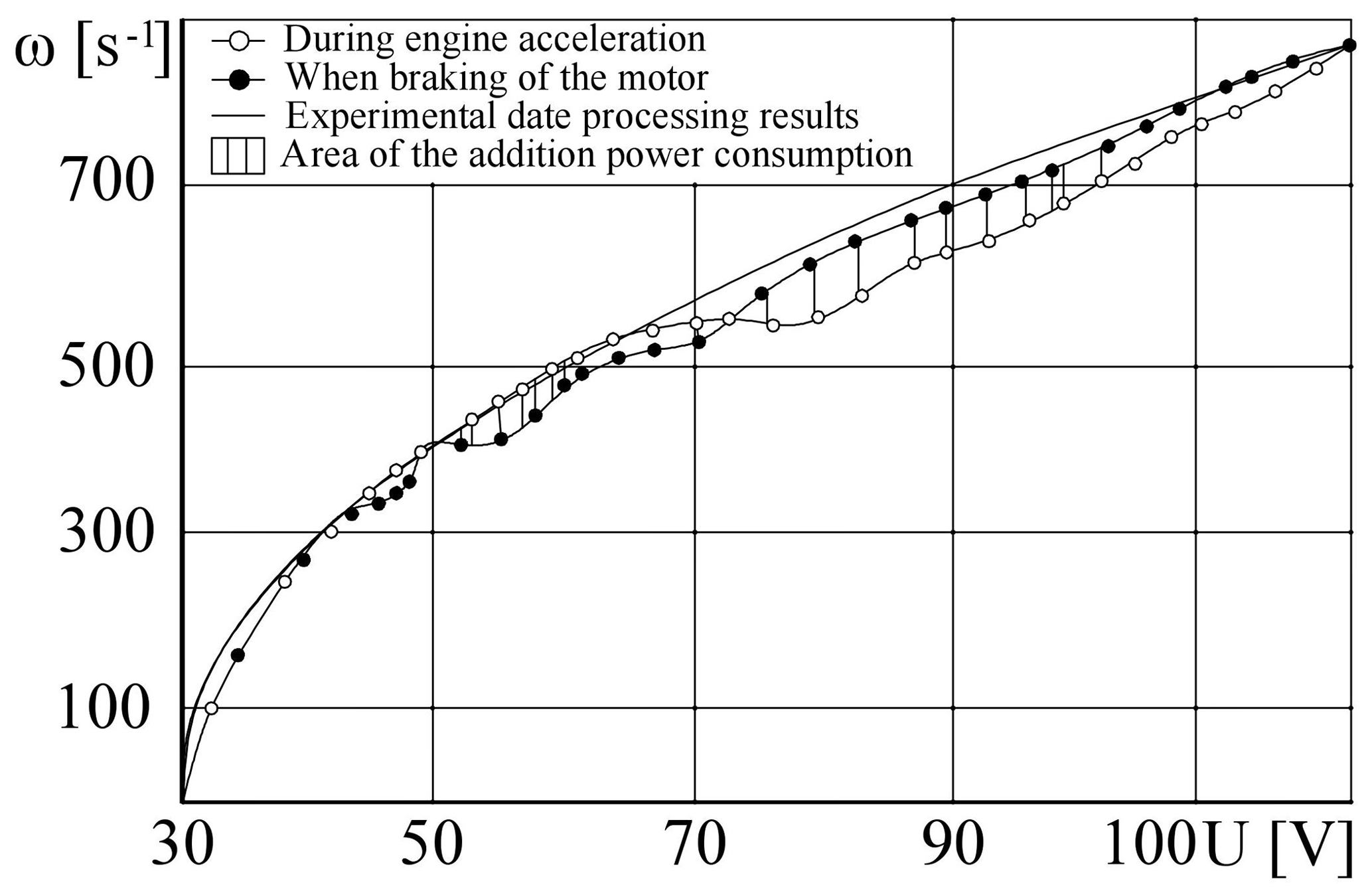
Figure 25Dependence of the shaft velocity on the tension applied to the engine in case of the fluoroplastic material of the rotor support.
Thus, selecting the values of the stiffness coefficient k, the linear damping coefficient μd1 and the coefficient of nonlinear cubic damping μd3 of the support, it is possible to create such an elastic support that would have simultaneously a restoring and damping impact on the resonance amplitude and enable the rotor to pass painlessly through the critical velocity. The restoring and damping properties of the support are the principle of operation of the centrifuge elastic support, which operates based on a gyroscopic rotor, for which the Kazakhstan patent of invention was obtained (Iskakov and Kunelbayev, 2018).
The invention is illustrated by drawings in Fig. 26. In Fig. 26, the driving electric motor (4) with the power take-off shaft (5) is strengthened on the platform (3) by means of the cylindrical ring (1) and the brackets (2). The electric motor shaft is connected to the power take-off shaft by a transient coupling (6). The driving electric motor with a power take-off shaft is attached to the frame by a lower hinge (7) and an upper spring (8) and rubber (9) elastic supports. A cylindrical vessel (10) is mounted on the upper conical part of the shaft (5) and is held on the shaft (5) by a lock nut (11). The cylindrical vessel has an internal lining (12) and is closed on top with a transparent cover (13). To measure characteristics of the precessional movement, the displacement sensors (14) are installed on the bracket (2), connected to the control device by wires (15), (16) and (17). To measure the shaft velocity (5), a magnetoelectric velocity sensor (18) is used, connected by wires (19) and (20) to the recording device in the control apparatus. The rotor velocity in the operating modes is set by the power source voltage regulator.
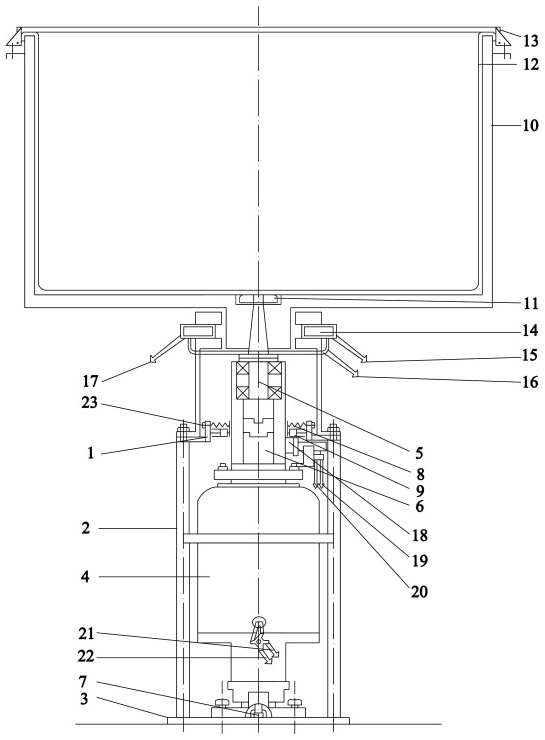
The electric motor is powered by wires (21) and (22). The shaft precession amplitude for the operating velocity and at full fill with liquid is regulated by tightening the spring of the upper elastic support (8) with the help of a nut (23), depending on the production process and product quality requirements. In this case, a rubber nozzle of the lower elastic support (9) is selected in such a way that the value of the vibration isolation coefficient (moment of force transmissibility of the system) of a special resin or rubber material is acceptable for safe passage through the critical velocity in case of determining the operating velocity beyond the critical velocity.
The following conclusions can be drawn based on the analysis and discussion of the research results:
The impact of an elastic bearing material with linear viscous damping and with cubic non-linear viscous damping on non-linear vibrations of a vertical hard gyroscopic rotor was studied, taking into account the non-linear stiffness of the elastic support.
The equations of motion of the rotor were composed based on the Lagrange's Equations of Second Kind, which were reduced to a dimensionless form.
The equations of motion of the rotor were solved by the harmonic balance method, and the expressions of amplitude-frequency and phase-frequency characteristics of the fundamental harmonic and the expression for determining the moment of force transmissibility of the system were obtained.
Researches of the amplitude-frequency characteristic depending on the coefficient of linear viscous damping and nonlinear viscous cubic damping of the elastic support showed that both linear and nonlinear cubic damping significantly suppresses the resonance amplitude of the fundamental harmonic, eliminate jumping effect of the nonlinear system.
In non-resonance areas, an impact of linear damping on the vibration amplitude is very weak and negligible, and nonlinear cubic damping in an area where the velocity is many times greater than its critical value can slightly suppress the amplitude of the rotor vibrations and, therefore, only nonlinear damping can maintain performance of the vibration isolator throughout the entire range of the rotor velocity.
The research results were used when preparing an application for a patent for invention of a gyroscopic rotor based centrifuge to develop a description, abstract and claims. The invented centrifuge can be used in pharmaceutical and food industries to effectively intensify the mixing of suspensions of medicinal herbs, dairy and cultured milk products, other liquid food products throughout the volume of a container due to controlled precession.
Our main research results prior to this publication are stored in the following public data repositories: https://doi.org/10.6567/IFToMM.14TH.WC.OS14.001 (Iskakov, 2015), http://www.proceedings.com/36097.html (Iskakov, 2015), https://doi.org/10.1007/978-3-319-45450-4 (Iskakov, 2017a), http://iftomm.net/images/Documents/ConferenceProceedings/ISMMS2017_Proceedings.compressed.pdf (Iskakov, 2017b), https://mes2018.aua.am/wp-content/uploads/2019/03/rus.pdf (Iskakov, 2018), https://doi.org/10.12955/cbup.v6.1319 (Iskakov, 2018a), https://doi.org/10.1007/978-3-030-20131-9 (Iskakov, 2019).
| Nomenclature |
|---|
| A= vibration amplitude, rad |
| Aτ= amplitude of the moment of transmitted force, dimensionless |
| e= linear eccentricity, m |
| G= disc weight, N |
| H= nominal thickness of the disc, dimensionless |
| IP= polar moment of inertia, kg m2 |
| polar moment of inertia, dimensionless |
| IT= transverse moment of inertia, kg m2 |
| transverse moment of inertia, dimensionless |
| k1= coefficient of linear stiffness, N m−1 |
| k3= coefficient of nonlinear stiffness, N m−3 |
| K3= coefficient of nonlinear stiffness, dimensionless |
| l0= distance between supports, m |
| L= shaft length, m |
| m= disc mass, kg |
| M= amplitude of the resultant moment, dimensionless |
| α= vibration phase, ∘ |
| γ = moment of force transmissibility, dimensionless |
| angles, rad |
| μd1= coefficient of linear viscous damping, N ms rad−1 |
| μ1= coefficient of linear viscous damping, dimensionless |
| μd3= coefficient of nonlinear cubic viscous damping, N ms3 rad−3 |
| μ3= coefficient of nonlinear cubic viscous damping, dimensionless |
| ω= shaft speed, rad s−1 |
| Ω= shaft speed, dimensionless |
| ω0= critical speed, rad s−1 |
ZI set a study objectives, formed differential equations of motion, worked on solution of differential equations of motion, prepared an analysis of the research results and a manuscript for the presentation. KB worked on numerical solution of differential equation of motion and participated in the analysis of the study results.
The authors declare that they have no conflict of interest.
This research has been supported by the The research work was funded by Ministry of Education and Science Republic of Kazakhstan on the basis of the Grant Financing of Scientific Research (grant no. 2263/GF4).
This paper was edited by Jahangir Rastegar and reviewed by Madan Lal Chandravanshi and one anonymous referee.
Felix, J. L. P., Almeida, A., Bianchin, R., Brasil, R. M. L. R. F., Rocha, R. T., and Balthazar, J. M.: On energy transfer between vibration modes and the frequency-varying excitations for energy Harvesting, in Proceedings of ICoEV 2015, Ljubljana, Slovenia, 7–10 September 2015, 1036–1045, available at: http://blog.espol.edu.ec/jpaezchavez/files/2015/08/ICoEV2015.pdf (last access: 1 October 2017), 2015.
Fujiwara, H., Nakaura, H., and Watanabei, K.: The vibration behavior of flexibly fixed rotating machines, in: Proceedings of the 14th IFToMM World Congress, Taipei, Taiwan, 25–30 October 2015, 2058–2063, available at: http://toc.proceedings.com/36097webtoc.pdf (last access: 1 October 2017), 2015.
Gil-Negrete, N., Vinolas, J., and Kari L.: A non-linear rubber material model combining fractional order viscoelasticity and amplitude dependent effects, J. Appl. Mech., 76, 9–11, 2009.
Hayashi, C.: Non-linear Oscillations in Physical Systems, chap. 1, 3–6, McGraw – Hill, 1964.
Ho, C., Lang Z., and Billings, S. A.: The benefits of non-linear cubic viscous damping on the force transmissibility of a Duffing-type vibration isolator, in: Proceedings of UKACC International Conference on Control, UK, Cardiff, UK, 3–5 September 2012, 479–484, 2012.
Iskakov, Z.: Resonant Oscillations of a Vertical Unbalanced Gyroscopic Rotor with Non-linear Characteristics, in: Proceedings of the 14th IFToMM World Congress, Taipei, Taiwan, 25–30 October 2015, 177–185, https://doi.org/10.6567/IFToMM.14TH.WC.OS14.001, 2015.
Iskakov, Z.: Dynamics of a Vertical Unbalanced Gyroscopic Rotor with Non-linear Characteristics, New advances in Mechanisms, Mechanical Transmissions and Robotics, Mech. Mach. Sci., 46, 107–114, https://doi.org/10.1007/978-3-319-45450-4, 2017a.
Iskakov, Z.: Resonant oscillations of non-balanced vertical gyro rotor with non-linear characteristics, in: Proceedings of the International Symposium of Mechanism and Machine, Science, AzTU, Baku, Azerbaijan, 11–14 September 2017, 240–246, 2017b.
Iskakov, Z.: Simulation of non-linear characteristics influence dynamic on vertical rigid gyro rotor resonant oscillations, in: Proceedings of the CBU International conference on innovations in science and education, Prague, Czech Republic, 21–23 March 2018, 1094–1100, https://doi.org/10.12955/cbup.v6.1319, 2018a.
Iskakov, Z.: Study of the influence of cubic nonlinear viscous damping on the resonance vibrations of the vertical hard gyro rotor, in: Proceedings of the International conference Mechanical engineering solutions: Design, Simulation, Testing and Manufacturing, Yerevan, Armenia, 17–19 Steptember 2018, 9–15, 2018b.
Iskakov, Z.: Resonant Oscillations of a Vertical Hard Gyroscopic Rotor with Linear and Nonlinear Damping Advances in Mechanism and Machine Science, Mech. Mach. Sci., 73, 3353–3362, https://doi.org/10.1007/978-3-030-20131-9, 2019.
Iskakov, Z. and Kalybayeva, A.: Oscillations and stability of vertical gyro rotor with disk tilt and mass disbalance, in: Proceedings of the International Symposium of Fundamental and Applied Science Problems, Moscow, RAS, 14–16 September 2010, 50–57, 2010.
Iskakov, Z. and Kunelbayev, M.: Centrifuge based on gyro rotor, Invention patent of the Republic of Kazakhstan, (19) KZ B (11) 32666 19 February 2018, bulletin no. 7, 42–43, 2018.
Kelzon, A. S. and Pryadilov, V. I.: Elimination of dangerous vibrations of vertical rotors, News AN SSR, Mechanics, 6, 42–48, 1965.
Kyderbekuly, A. B.: Oscillations and stability of rotor systems and plane mechanisms with non-linear rigid characteristics, Doctor of Engineering Science Dissertation: 1 February 2006, Institute of Mechanics and Machine Science, Almaty, 271 pp., 2010.
Mallik, A. K., Kher, V., Puri, M., and Hatwal, H.: On themodelling of non-linear elastomeric vibration isolators, J. Sound. Vib., 219, 239–253, 1999.
Panovko, Ya. G.: Introduction to mechanical oscillations theory, Moscow, Nauka, 249 pp., 1971.
Peng, Z. K., Mengand Lang, Z. Q., Zhang, W. M., and Chu, F. L.: Study of the effects of cubic non-linear damping on vibration isolations using Harmonic Balance Method, Int. J. Nonlin. Mech., 47, 1065–1166, 2012.
Ravindra, B. and Mallik, A. K.: Performance of non-linear vibration isolators under harmonic excitation, J. Sound. Vib., 170, 325–337, 1994.
Richards, C. M. and Singh, R.: Experimental characterization of non-linear rubber isolators in a multi-degree-of-freedom system configuration, J. Acoust. S. Am., 106, 21–78, 1999.
Szemplinska-Stupnicka, W.: Higher harmonic oscillations in heteronymous non-linear systems with one degree of freedom, Int. J. Nonlin. Mech., 3, 17–30, 1968.
Tondl, A.: Dynamics of rotors of turbogenerators, Energy, Leningrad, 388 pp., 1971.
Tuleshov, A. Z.: Fluid-elastic vibrations of the vertical rotor at a limited power source, 5 February 18 – Theory of Mechanisms and Machines, abstract for a degree of Candidate of Science, S. M. Kirov Kazakh State University, Almaty, 23 pp., 1987.
Van Dooren, R.: Combination tones of summed type a non – linear damped vibratory system with two degrees of freedom, Int. J. Non-lin. Mech., 6, 237–254, 1971.
Vishnevsky, S. N.: Calculation of characteristics and resistances of electric motors, Gosenergoizdat, Moscow, 336 pp, 1955.
Yablonskiy, A. A.: Oscillation theory course, Study guide, BHV – St. Petersburg, 336 pp., 2007.
Zakaria, A. A., Rustighi, E., and Ferguson N. S.: A numerical investigation into the effect of the supports on the vibration of rotating shafts, in: Proceedings of the 11th International Conference on Engineering Vibration, Ljubljana, Slovenia, 7–10 September 2015, 539–552, 2015.
Zapomel, J. and Ferfecki, P.: Mathematical Model of a Short Magnetorheological Squeeze Film Damper Based on Representing the Lubricating Oil by Bilinear Theoretical Material, Proceedings of the 14th IFToMM World Congress, Taipei, Taiwan, 25–30 October 2015, 186–191, 2015.
- Abstract
- Introduction
- Motion equations
- Amplitude- and phase-frequency characteristic and moment of force transmissibility of the system
- Impact of damping on rotor dynamics
- Motion stability
- The dynamics of the experimental rotor
- Conclusions
- Data availability
- Appendix A:
- Author contributions
- Competing interests
- Financial support
- Review statement
- References