the Creative Commons Attribution 4.0 License.
the Creative Commons Attribution 4.0 License.
 | 20 Nov 2018
Kinematic analysis and optimization of a planar parallel compliant mechanism for self-alignment knee exoskeleton
Yijun Niu
Jiansheng Dai
Misalignment between the instantaneous center of rotation (ICR) of human joint and the ICR of wearable robotic exoskeleton widely exists among most of exoskeletons widely used in rehabilitation, which results in discomfort, even endangers human safety. In order to alleviate it, this study focuses on the solution of misalignment in knee joint of lower limb exoskeletons, and proposes a compliant five-bar parallel mechanism, which offers two mobility in sagittal plane, as well as the torsional springs mounted on this mechanism, have the potential to automatically adjust the ICR of output link connected to thigh with respect to the basis link connected to shank. To reach this goal, we build the stiffness model of the mechanism and optimize its variables. And the self-alignment of the compliant five-bar parallel mechanism is verified via experimental investigations.
- Article
(4480 KB) - Full-text XML
- BibTeX
- EndNote


Wearable robotic exoskeletons have been researched for several years, and they are widely applied in various fields ranging from rehabilitation of patients (Hesse et al., 1995) to performance assistance (Zoss et al., 2006). Most of the devices are designed to mimic the motions of users, especially the assisted rehabilitation exoskeletons, which provide physical exercises by imitating the pattern of the movement of human limbs (Wong et al., 2012).
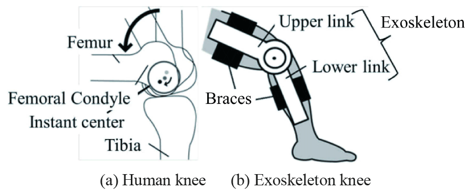
Keeping the correspondence of robotic exoskeleton rotating axes with human joint axes is a necessary criterion. The majority of exoskeleton rotary joints are typically modeled as hinges, however, due to the limitation of the unicentric feature, these mechanisms have a drawback of causing misalignment, in other words, causing inconsistency between human limbs and exoskeleton during movement, even though their initial positions are carefully aligned. Human joints cannot be assumed as simple kinematic pairs, since human skeletal structure consists of bones, ligaments and cartilage, and this intricate structure results in complicated kinematics of joints. Human knee is one of the most typical joints where misalignment exists. As shown in Fig. 1, the anomaly geometry of tibial and femoral condyles combined with restriction of collateral tendons influence the movement of human knee joint axis in the sagittal plane. This axis is the instant center of knee rotation, which is a composite motion shown as the combination of rolling and gliding movements within a circular scope with a diameter of 20 mm (Smidt, 1973; Frankel and Nordin, 1980; Yamaguchi and Zajac, 1989). Moreover, the variability of intra/intersubjects also negatively affects the correspondence between exoskeleton axes and the human limb joints (Zanotto et al., 2015), in view of the twisting and sliding movements of the attachment area of the limb, as well as differences among different users. There is also a fact that robotic exoskeleton inevitably add weight, inertia and friction to legs (Aguirre-Ollinger et al., 2011), and once human/robot misalignment goes worse, these uncompensated mechanical impedance will severely hinder the agility of movement, or generate undesired forces or torques to the limbs and joints because of hyperstaticity of the closed-chain mechanism, leading to malaise, even injury (Zanotto et al., 2015; Aguirre-Ollinger et al., 2011).
In the past, the majority of designs aimed to handle the misalignment in the upper extremity exoskeletons (Yalcin and Patoglu, 2012; Cempini et al., 2013; Otten et al., 2015), and recently there comes out plenty of researches focusing on lower extremity exoskeletons. Sun et al. (2015) proposed a prosthetic knee joint with a geared five-bar mechanism, which can directly modify the joint trajectory via adjusting the gear ratio. Nevertheless, motions of two links of this mechanism are mutual coupling, such that the trajectory of the joint is determined in advance, and during the movements, this design cannot solve the changing misalignment in the real time. Furthermore, this design only can fine-tune its output in a narrow range, which cannot meet demands of different users. Cai et al. (2009) introduced a knee orthosis to alleviate the internal forces produced by misalignment, and it was added with additional mobility and can adjust the ICR of the exoskeleton. Due to the length-adjustable links, this design is able to self-adjust without resorting to motorized add-ons, and reversely, it brings about unconstraint passive movement, which makes it impossible to sufficiently support little weight and potentially lead to instability. Moreover, referring to a trajectory of the ICR of knee joint, Sakai et al. (2015) proposed a device with the combination of sliding channel and wire-pulley, and its rotational center could keep pace with that of human femur. However, this design determined the trajectory of its motions based on a specific motion data, which in turn make itself fail to fit other individuals. Some studies achieved self-alignment by using amounts of sensors and control system in exoskeleton (Krut et al., 2010; Zoss et al., 2016). Those solutions compensate the misalignment by observing the macroscopic deviation, and guide the position or the torque of the human joints. Even though these approaches offer an exact adjustment for each user's knee joint, measuring a mass of explicit data costs too much and the equipment is bulky and heavy. And the user will suffer from the frictional force at the attachment position and feel uncomfortable and painful, as a result, fall into a risky situation (Pons et al., 2010). In general, even though certain studies developed some approaches could attenuate the misalignment, their mechanisms have some common disadvantages, such as increasing design complexity, being unfeasible for different individuals or loading undesirable force or torque on users.

Now that the extension and flexion motions of human knee are not unicentric, for the purpose of better bionic performance, some exoskeletons switched to adopt multiaxial joints instead of traditional uniaxial joints. Many prosthetic knee technologies are designed based on the four-bar mechanisms (Hobson et al., 1974; Radcliffe, 1977, 1994; Muñoz-César et al., 2013), which offer bionic relative ICR and enhance safety and comfortability in movements. While some six-bar mechanisms (Jin et al., 2003) are developed, and these multiaxial knee joints have polycentric characteristic to make the ICR of prosthetic joint closer to that of human knee joint in walking experience. Nevertheless, the four-bar mechanism only have one mobility and cannot flexibly change its configuration to provide diverse movements in self-adjusting to human body, and as for the six-bar mechanism, it has much more various structure and needs complex controllability. By contrast, five-bar mechanism is more flexible than four-bar and more controllable than six-bar.
This research brings a parallel compliant five-bar mechanism on the carpet which can provide a self-alignment to the movements of human knee. It has two degrees of freedom to allow random movements in sagittal plane. In order to realize real-time self-alignment in extension and flexion processes, present a better bionic performance as well as reduce the load of the exoskeleton, this study suggests to introduce compliant parts at the joints of the exoskeleton mechanism. Thus, a concept of mechanical compliance is taken into account which can automatically change the kinematic variables of the mechanism to fit the limb movements, owning to the design of the mechanism with special stiffness characteristics rather than explicit control system. Due to compliant feature and absence of fixed axis, this mechanism has better bionic performance to follow the human motions, safely and automatically.
The rest of the article is organized as follows: In Sect. 2, the structural design of the planar parallel compliant five-bar mechanism is introduced. In Sect. 3, the integrated kinematic model of the proposed mechanism is built and derived. In Sect. 4, the variables of the mechanism are optimized by using GAs method. Moreover, method of evaluating the risk caused by misalignment is discussed, and the self-aligning performance of the mechanism is estimated by conducting a series of experiments in Sect. 5, followed by conclusions in Sect. 6.
The planar parallel compliant five-bar mechanism, assembled in the sagittal plane of the exoskeleton, is a closed chain and substitutes for the traditional joint. As shown in Fig. 2, the structure is designed as a symmetric form so as to simplify the calculation process, link AE works as the base frame and rigidly connects to the shank exoskeleton, while the thigh exoskeleton is connected to joint C with a hinge. Five torsional springs are respectively mounted on each joint. Those springs are initially installed without internal preload torque distribution, which simplifies the process of installment. And the whole exoskeleton is tightly attached to human limbs with braces. To enable the mechanism to transform its configuration flexibly and efficiently, the wearing of the exoskeleton must ensure the extension and flexion of knee joint is within the working scope of the five-bar mechanism even though the attachment positions are arbitrary.
During the knee extension and flexion motions, a little disconformity between human and exoskeleton movements will generate corresponding force acting on the thigh bar, then impose a load on the compound hinge C. Since the mobility of this mechanism is two, its output (end effector) joint C can move freely within the working space. When loaded, the compliant five-bar mechanism will approach to a stable state, thus, external work will converse into elastic energy stored in the torsional springs. And the deformation of the mechanism can reduce the relative human/robot misaligned wobble movement, making the exoskeleton self-align to human body. On the other hand, the point C serves as the output of the mechanism as its position reflects the corresponding configuration of the mechanism. In fact, there is no fixed mechanical rotation center for the five-bar mechanism and this compliant device has a potential to adjust itself to fit the polycentric motions of the human joint axis, and simultaneously offer self-alignment to the exoskeleton without measuring the explicit ICR of human joint.
In order to provide with suitable and effective self-alignment, motion capabilities of the mechanism are crucial issues. The movement characteristics and precision of the end effector are directly related to the stiffness of the mechanism, such that this research uses a decoupling method to obtain the stiffness matrix of the mechanism. With this method, we can figure out the mathematical problems in torque distributions of the mechanism during extension and flexion. In view of the process of squatting which involves the largest flexion range of human knee joint and induces the larger misalignment, it is a relative slow motion, and the kinematic stiffness is a static approximation and can be calculated by deriving the torque and force with respect to the infinitesimal angular changes of joints or the infinitesimal deformation.
3.1 Forward kinematics and constraint Jacobians
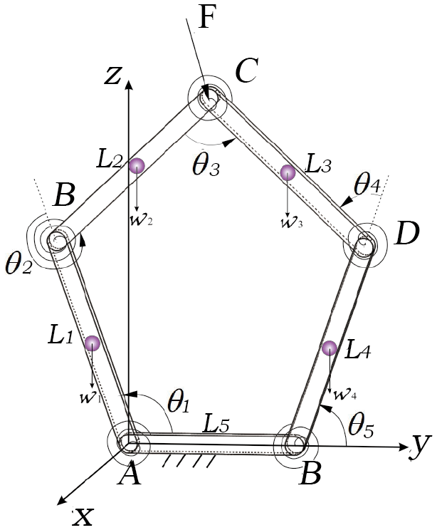
The parallel compliant five-bar mechanism is modeled in Fig. 3. Li (i=1–5) indicates the length of each bar, A∼E respectively indicates each joint, θi represents the corresponding joint angle, and F is an external force applying on the joint C.
Presuming this mechanism is separated from point C into two kinematic open chains, the left one is assumed to be the independent chain, while the right one, including the joint C, is the dependent chain. The final position of the end effector of the mechanism is related to the given angle of left chain, and can be obtained by analyzing the forward kinematics:
Differentiate Eq. (1) with respect to time, the relationship is obtained:
JL is the forward Jacobian of left chain, and it associates the angular velocities of joints to the velocity of the point C.
The mapping relationship between angular velocities of these two chains is obtained from the kinematic constraint equations, which are built on account of the closed-chain characteristics of the mechanism, as shown in Eq. (3):
Time derivative of Eq. (3):
where G=(G1 G2 G3)T, Let , and are separately the angular velocity vectors for the left and right chains, and relationship between the angular motions of two chains can be obtained as follows:
where GL and GR are respectively the corresponding first-order influence coefficient matrices for the two chains (Huang, 1985; Hudgens and Tesar, 1991).
Let Ju express the influence matrix for the motions propagation between the two chains, then
where .
3.2 Stiffness model of the parallel compliant five-bar mechanism
During the motion of the end effector, external loads acting on joint C generate torques at joints for the compliant effects. Assuming no friction applied on the mechanism, the virtual work principle is used to establish a torque equilibrium.
where , , ωi)T indicates the three dimensional velocity of link i, as described in more detail in the section D; represents the vector of each link's gravity; is the velocity vector of joint C; indicates the external force applied at joint C; and respectively express the angular velocity vectors for left and right chains, which are obtained by decomposing the five-bar mechanism from point C; , indicate the torques on the joints of left and right chains, respectively.
Substituting Eqs. (2) and (6) into (7), and eliminating , yields:
Differentiating with respect to time, the relationship between the payload force and the infinitesimal incremental changes of the joints is obtained:
where the gravity of links are constant, such that δwi=0.
The first term of the equation can be rewritten:
The Hessian matrix Hi is defined as an influence coefficient matrix of the second-order partial derivatives of a scalar-valued function (Huang, 1985; Hudgens and Tesar, 1991; Huang et al., 1997). In this study, Hessian matrix involved in the stiffness analysis denotes the derivative of the transposition of several coefficient matrices with respect to the angular changes of joints in the independent chain, including angular velocity matrices of two links, the mapping relationship between two chains and the forward Jacobian. Furthermore,
where , is the stiffness matrix of the joints separately in the left and right chains.
Substituting Eqs. (10)–(14) into Eq. (9) and yields:
Due to the mapping relationship, the displacements of the joints in the left link δqL can be substituted by a function of the incremental displacement of the end effector .
Therefore,
The stiffness matrix of the complaint mechanism is obtained by rearranging the Eq. (16)
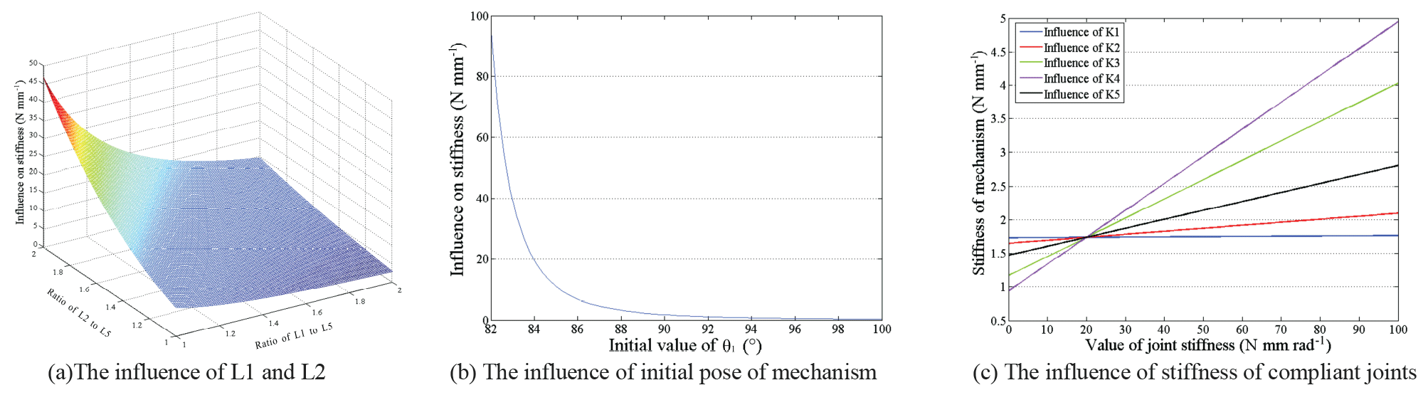
Based on Eq. (17), the stiffness characteristics of the compliant five-bar mechanism respect to its variables are discussed via simulations, where the lengths of links are normalized to the length of base frame; the variation range of the initial angle is decided according to installation space and the stiffness value of the unstudied torsional springs is defined as 20 N mm rad−1. As shown in Fig. 4, (a) suggests the relation of links and the mechanism stiffness; (b) indicates that the stiffness value varies drastically as tends to and the relative influence of each joint stiffness to the system is indicted in (c).
3.3 Directional characteristics of stiffness
This compliant five-bar mechanism is a complex spring system, and the stiffness analysis exploits the motion of the end effector. In this research of the lower extremity exoskeleton, we concern about the misalignment problem which expresses as the radial wobble movement of the output point C, and this exoskeleton should not hinder extension/flexion motions, which means the output can freely move in circumferential direction. In this section, the directional stiffness characteristics of the end effector of the mechanism is discussed.
Suppose that the stiffness matrix of the mechanism is K. When misalignment happens, an infinitesimal force is exerted on the end effector, and the corresponding infinitesimal movement δDC is produced, which can be distributed into radial and circumferential components of displacement. And the relationship between them gives
where δDC indicates the displacement distance; Kij indicates elements of the compliant matrix K and αD indicates the angular separation of the disquisitive direction.
Thus, the directional stiffness of the end effector point C in the αD direction is defined as
The radial stiffness KR and the circumferential stiffness KC of the mechanism is obtained by substituting into the corresponding directional angle values.
3.4 Derivation of velocity of each link
To investigate the stiffness constraint of the end effector of closed-chain mechanism, the gravitation of each link also need to be taken into account. And indicate the three-dimensional velocity of link i, in which ci represents center point of mass of each link, and since the velocity relationship of two point on the same rigid body: and , an expression of the velocity is obtained as:
where is the transformation matrix of analyzing positions; is the instantaneous motion of link i, and Oi indicates the point attached to the link and instantaneously coincident with the original point.
Each link's rotor Ti is related to the joints' angular motions:
As what have been discussed before, is the Jacobian of the left chain, and likely, is the Jacobian of the right chain. Ji are the vectors representing the mapping coefficient between velocity of the end effector and the angular velocities of corresponding joints, and .
Substituting Eqs. (21) into (20) gives
where G1, , G3, .
4.1 Parameters optimization
Optimization of stiffness is widely concerned in mechanical designs, such as increasing the isotropy of stiffness (Shin et al., 2013; Hao and Li, 2016), maximizing stiffness in one direction (Lee et al., 2011; Hao, 2017), and maximizing stiffness in all directions (Shin et al., 2007). In this research, we primarily concern about the magnitude and anisotropy of stiffness matrices, and furthermore optimize the mechanical parameters to improve the performance.
This part presents a parameter optimization of the planar mechanism. The stiffness distribution of the compliant mechanism is mainly related to the geometric dimensions, stiffness of each compliant joints and initial configuration. In order to provide with enough support in radial direction when the user wears the exoskeleton and stands erectly, this mechanism is supposed to only have slight deformation so as not to cause discomfort. In addition, this exoskeleton should have a relatively flexible feature to assist the user in bending and stretching knees, such that an optimization is performed to locate a larger system radial stiffness whereas the circumferential stiffness is relatively smaller.
The genetic algorithms (GAs) was applied to optimize the design parameters. GAs are global search methods inspired by natural selection, and operate with populations of individuals of an optimization problem (Chi and Zhang, 2012). These populations evolve toward better solutions, and individuals in a population are evaluated about their fitness that reflects how well the optimization problem been solved. In this section, we applied the GAs in the determination of parameters that effects the stiffness in radial and circumferential direction respectively denoted by KR and KC. Since the initial configuration of the mechanism is symmetric, l1=l4, l2=l3, and the length of the base link is 50 mm with the consideration of size of human knees. Thus, we only need to optimize the ratio value of the length of each link to that of base frame in one chain, stiffness of each joint and the initial angle θ1. Therefore, the optimization process, minimizing the ratio ( of KC and KR, can be expressed as:
where x1, x2 indicate the ratio value of link l1, l2 to l5.
According to the magnitude of the knee part of the exoskeleton and the stiffness requirements, optimization function subjects to the following constraint conditions:
4.2 Optimization results based on the working pattern
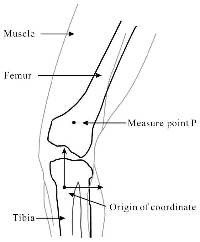
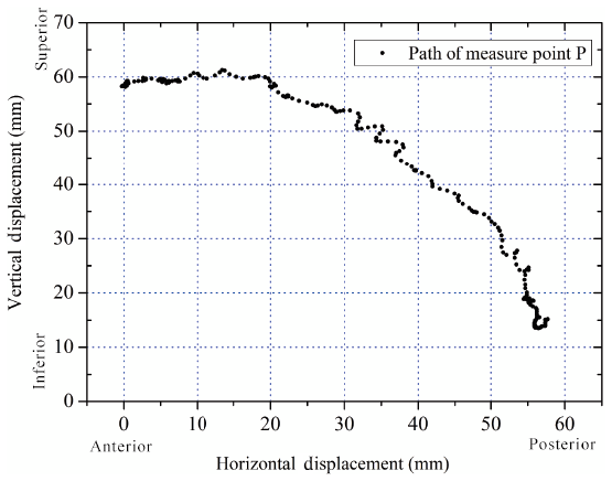
The workspace, determined by the design of the mechanism, is related to dimension of human knee joint. As shown in Figs. 5–6, a sample is given by a 23-year-old Asia female of 165 cm in height. According to the definition of the coordination system in the article (Andriacchi et al., 1998), the coordination system of tibia and femur is built, and a two-dimensional tibiofemoral joint model is obtained by using 3-D Guidance driveBAY and trakSTAR.
The workspace of the mechanism should cover the whole path of the measuring point P as shown in Fig. 7. During movement, this mechanism deforms toward one side, and the displacement of the end effector can be decomposed into radial motion xR and circumferential motion xC.
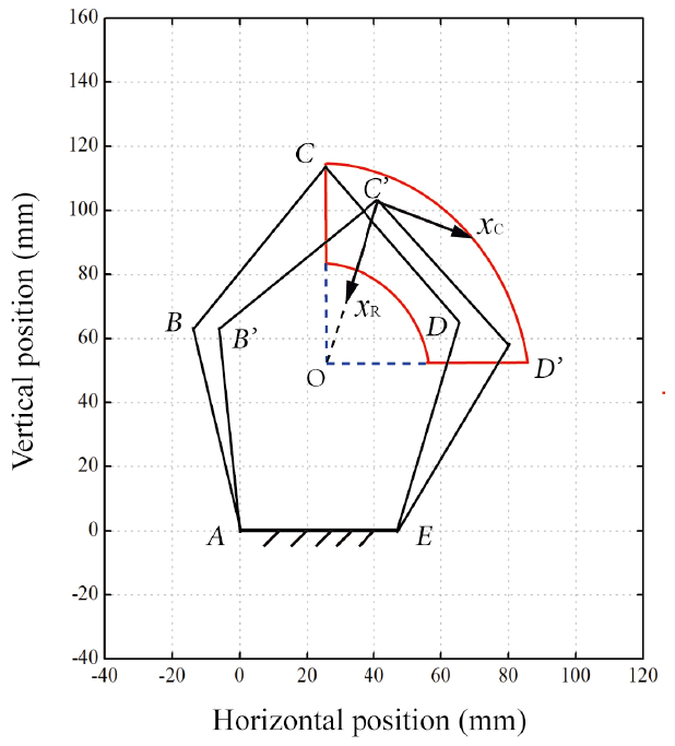
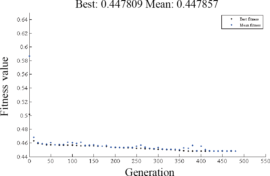
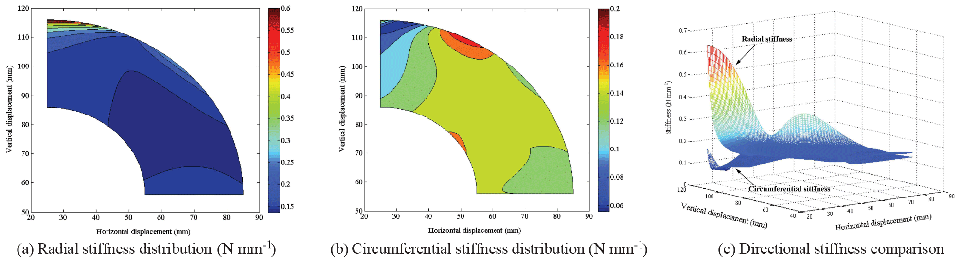
Figure 9Stiffness distribution in radial and circumferential directions. The workspace is assumed to be an annular sector with radii (mm) and angle 90∘ (measured in radian), basing to the sample data.
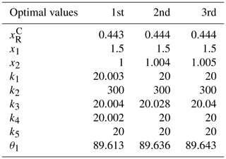
The MATLAB GA toolbox is implemented to finish this optimization. After 482 generations, the objective function Eq. (23) is convergent to minimum point as shown in Fig. 8 in which the fitness value dropped from the initial 0.59, and the best variables are revealed in Table 1.
4.3 Stiffness distributions based on the optimization
According to the results of optimization, the stiffness distribution diagrams are obtained via MATLAB. As shown in Fig. 9, the stiffness in two directions has large discrepancy initially, and the radial stiffness is far larger than the circumferential stiffness when the user just put on the exoskeleton. And the mechanism become softer in radial direction during leg flexion because the corresponding stiffness gets smaller when loaded, such that the mechanism become elastic in radial direction and can respond freely to the applied force on the point C.
Moreover, when the end effector reaches up to relative higher position, radial stiffness abruptly increase for the mechanism is near to the singular configuration. This characteristic meets our expectation for the mechanism, since the weight of the whole exoskeleton is 1.6 kg, and due to the braces sharing the most of it, only a fraction of the load is applied on the five-bar mechanism. Substituting the optimized results into Eq. (22), we received the directional stiffness: KR=0.568 N mm−1, KC=0.057 N mm−1. Therefore, the radial stiffness is large enough to support the initial load, and the smaller circumferential stiffness can let users bend their legs smoothly. Through optimizing these variables, the mechanism performance is improved.
This section presents the experimental verification of the self-aligning performance of knee exoskeleton. It is difficult to detect the explicit trajectory of both ICRs of human knee and exoskeleton joint externally during extension or flexion. When operating a traditional wearable exoskeleton, the user receives force from the exoskeleton through the braces (Akiyama et al., 2012; Zanotto et al., 2015), and the tangential component of this force is undesirable, since it is accompanied by the human/robot misalignment. Therefore, the tangential interaction force can be utilized to effectively assess the self-alignment ability of the exoskeleton. Moreover, a motion measurement is conducted to validate the adaptation of the exoskeleton.
5.1 Self-alignment assessment based on force measurement
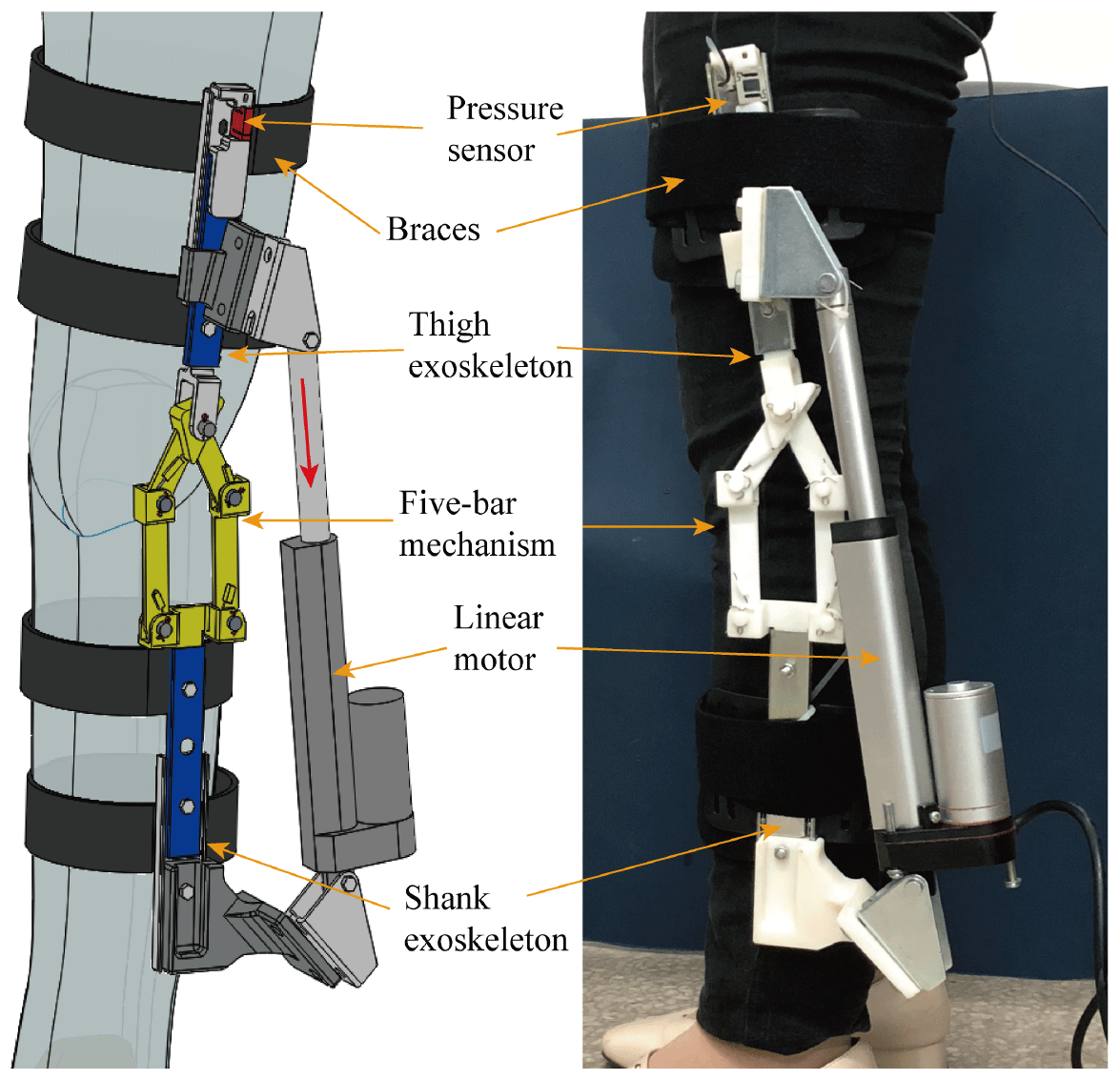
We adopted the filtering criterion based on a simple ergonomics principle (Accoto et al., 2014): a correct interaction requires forces to be applied perpendicularly to the human body segments since tangential forces (shear forces), besides being ineffective for motion generation, may cause discomfort or even tissue damage. Therefore, in the verification of being able to mitigate the misalignment, it is not definitely required to identify the explicit ICR of the human knee or exoskeleton if the tangential interaction forces conform to ergonomics principle. As shown in Fig. 10, we conducted experiments on the subject. According to the results of the optimization, selection of parts and assembly of the five-bar mechanism are completed, and a linear motor is parallelly connected to the exoskeleton mechanism and set up a closed-chain structure. Then this whole exoskeleton is tightly attached to human thigh and shank with four braces at a natural standing position, in order to prevent links from oscillating in the experiments. A pressure sensor JLBS-MD is mounted on the exoskeleton, Since the misalignment will cause tangential interaction force thigh between human thigh and exoskeleton rod, this sensor is used to measure the tension and compression force which can reflect the extent of human/exoskeleton misalignment. The self-adjusting ability of the compliant five-bar mechanism is evaluated by analyzing the results measured by the sensor.
The first group (I and II) studies the process of sitting down and standing up, and the second group (III and IV) studies the actual walking condition.
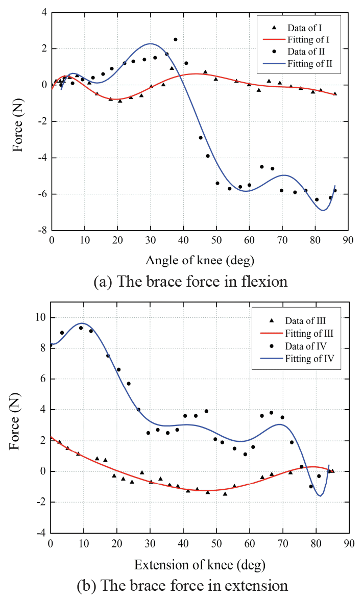
The experiments of the mechanism are conducted in practical situations, and knee flexion is performed in experiment I in which the user sits down from a standing posture. To assess the performance objectively, experiment II is measured by using a traditional reference exoskeleton mounted with hinge knee joint. Experiment III is under the circumstance that the user extends knees and stands up from a sitting posture, and IV is the corresponding contrast experiment of it. As depicted in Fig. 11.
In Fig. 11, II and IV indicate that the interaction force at the position of thigh brace have similar tendencies whether in extension or in flexion, which suggests this experiment is unaffected by human factors and it is irrelevant to motion forms. Moreover, when the knee angle is about 90∘, oscillating scatters appear much more turbulent. This is because the influence of friction between human leg and exoskeleton overpowered the misalignment when near squatting position.
And in the tests of reference exoskeleton, trends of the interaction force shown in Fig. 11 II and IV indicate that thigh receives increasing pressure at the brace position during knee flexion, whereas the tendency converts to decreasing pressure and increasing tension during knee extension. One assumed reason for this is the distance amount between these two attachment area of the leg has larger range of variation than the exoskeleton does, and it becomes longer than the device during extension as well as it gets shorter than the device during flexion. In the calculation, the attachment area of the thigh endure dramatic displacement and force change in the traditional exoskeleton experiment. Furthermore, based on the comparison of the results of measuring force of the reference and self-aligning exoskeletons, it clearly shows that measured curve of the self-aligning exoskeleton is less turbulent and smoother than the reference one, and the mechanism also narrow the range of interacting force by more than 85 %. Therefore, this experiment validates the device can effectively attenuate the misalignment between human and exoskeleton, and the design could to a great extent provide with gentle and comfortable experience for users.
As shown in Fig. 12, the user finished four gaits in each experiment, in which V is conducted by using the proposed exoskeleton, and VI is the contrast test. Human/exoskeleton interaction force is much more turbulent and reaches to extreme values at the boundaries between (a) stance phase and (b) swing phase. Because at these position, the angle of human knee respectively reaches to the most exceeding misalignment case. In contrast, from the comparison of the maximum ranges of peak-to-peak, the force drawing by using proposed exoskeleton reflects the human gaits in a much flatter way. Thus, the ability of self-aligning the compliant five-bar mechanism knee joint performs better than the traditional knee.
5.2 Self-alignment assessment based on motion measurement
Given that both of the tangential interaction force and relative movement between human and exoskeleton reflect the misalignment, to validate the self-alignment of the mechanism, motion adaptation also needs to be investigated. In the process of walking, a displacement sensor is installed on the thigh link of exoskeleton at point Q, which is initially coincident with the measuring point P on the subject mentioned in Fig. 6. Furthermore, according to the trajectory of point P, we track the moving path of the corresponding point Q on the exoskeleton and detect the gap between paths of these two measuring points. Measurements of force and motion are drawn in the same figure.
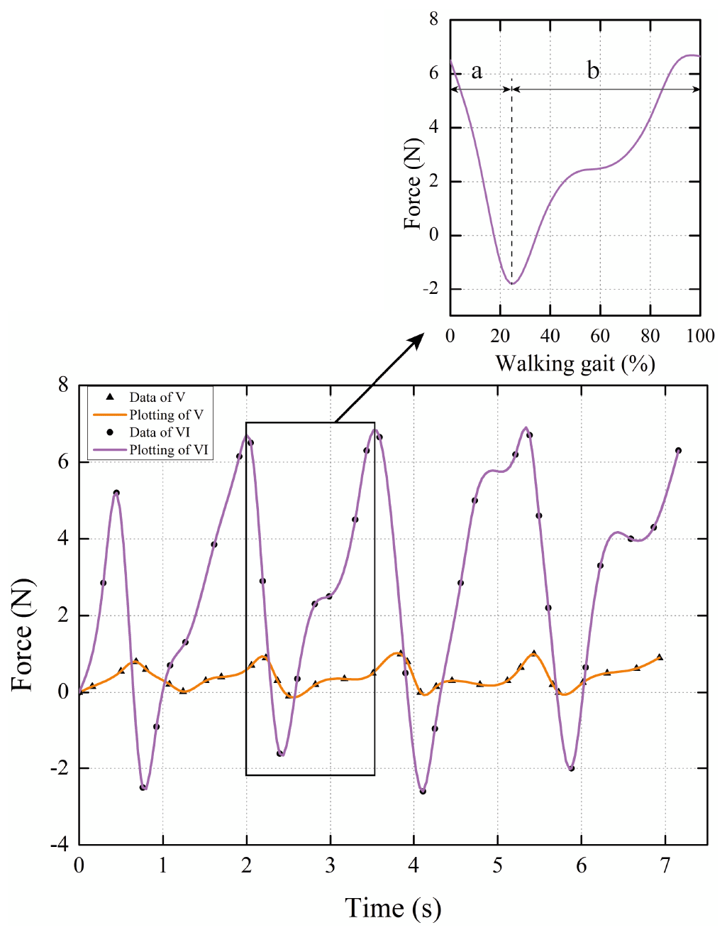

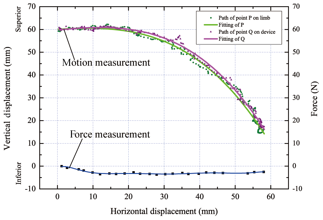
Figure 14Motion comparison between measuring points on human and exoskeleton & corresponding force measurement.
As shown in Fig. 14, fitting curves of these two trajectories of measuring points on the subject and exoskeleton are ultimately consistent, and apparently the gap value is very small, which is in accordance with the force fluctuation as the pressure is getting larger at the same period, which indicates that the proposed knee exoskeleton sufficiently adapts the movement of human knee joint. Meanwhile, the tangential interaction force is small and has little fluctuation. The proposed exoskeleton is able to self-align to human knees.
In order to reduce the misalignment problem in using the traditional lower extremity exoskeletons, we propose a novel design, which provides an implicit self-alignment to human knee joints, and such ability is related to the structural design and human loads. Such that the kinematic characteristics is analyzed and the stiffness matrix is obtained, which provides a necessary basis for further optimization. The experiment investigation, including motion and force tests, validates the self-alignment capacity of knee exoskeleton design.
Most recent designs of upper limb tend to introduce passive auxiliary mechanisms to alleviate misalignment at the elbow and shoulder joints. Nevertheless, such mechanisms might not be necessary for the case of lower extremities exoskeletons, provided that a parallel compliant mechanism is utilized to significantly reduce the effects of knee misalignment, especially on the tangential interaction forces at the thigh/brace interfaces, and this approach effectively guarantee the comfort and safety for users.
A portion of the underlying research data are presented in the text, and the rest cannot be shared at this time as the data also form part of an ongoing study.
The manuscript was written through contributions of all authors. All authors have given approval to the final version of the manuscript.
The authors declare that they have no conflict of interest.
This work was supported by the National Natural Science Foundation of China
(Project no. 51475322, 51535008, 51775367, 51721003), the Tianjin Municipal
Science and Technology Department Program (Grant no. 17JCZDJC30300), and the
international collaboration programme under Grant no. B16034.
Edited by: Guangbo Hao
Reviewed by: two anonymous referees
Accoto, D., Sergi, F., Tagliamonte, N. L., Carpino, G., Sudano, A., and Guglielmelli, E.: Robomorphism: a nonanthropomorphic wearable robot, IEEE Robot. Autom. Mag., 21, 45–55, 2014.
Aguirre-Ollinger, G., Colgate, J. E., Peshkin, M. A., and Goswami, A.: Design of an active one-degree-of-freedom lower-limb exoskeleton with inertia compensation, Int. J. Robot. Res., 30, 486–499, https://doi.org/10.1177/0278364910385730, 2011.
Akiyama, Y., Yamada, Y., Ito, K., Oda, S., Okamoto, S., and Hara, S.: Test method for contact safety assessment of a wearable robot-analysis of load caused by a misalignment of the knee joint, 2012 IEEE RO-MAN: The 21st IEEE International Symposium on Robot and Human Interactive Communication, 539–544, https://doi.org/10.1109/ROMAN.2012.6343807, 2012.
Andriacchi, T. P., Alexander, E. J., Toney, M. K., Dyrby, C., and Sum, J.: A point cluster method for in vivo motion analysis: applied to a study of knee kinematics, J. Biomech. Eng., 120, 743–749, 1998.
Cai, D., Bidaud, P., Hayward, V., and Gosselin, F.: Design of self-adjusting orthoses for rehabilitation, Proceedings of the 14th IASTED International Conference Robotics and Applications, Cambridge, MA, USA, 2–4 November 2009, 215–223, 2009.
Cempini, M., De Rossi, S. M. M., Lenzi, T., Vitiello, N., and Carrozza, M. C.: Self-Alignment Mechanisms for Assistive Wearable Robots: A Kinetostatic Compatibility Method, IEEE Trans. Robotics, 29, 236–250, 2013.
Chi, Z. and Zhang, D.: Multi-objective optimization of stiffness and workspace for a parallel kinematic machine, ASME International Design Engineering Technical Conferences and Computers and Information in Engineering Conference, 485–495, 2012.
Frankel, V. H. and Nordin, M.: Basic biomechanics of the skeletal system, Lea & Febiger, 1980.
Krut, S., Benoit, M., Dombre, E., and Pierrot, F.: Moonwalker, a lower limb exoskeleton able to sustain bodyweight using a passive force balancer, IEEE International Conference on Robotics and Automation (ICRA), Anchorage, AK, USA, 3–7 May 2010, https://doi.org/10.1109/ROBOT.2010.5509961, 2010.
Hao, G.: A framework of designing compliant mechanisms with nonlinear stiffness characteristics, Microsyst. Technol., 24, 1795–1802, 2017.
Hao, G. and Li, H.: Extended static modeling and analysis of compliant compound parallelogram mechanisms considering the initial internal axial force, J. Mech. Robot., 8, 041008, https://doi.org/10.1115/1.4032592, 2016.
Hesse, S., Bertelt, C., Jahnke, M. T., Schaffrin, A., Baake, P., Malezic, M., and Mauritz, K. H.: Treadmill training with partial body weight support compared with physiotherapy in nonambulatory hemiparetic patients, Stroke, 26, 976–981, 1995.
Hobson, D. A. and Torfason, L. E.: Optimization of four-bar knee mechanisms – A computerized approach, J. Biomech., 7, 371–376, 1974.
Huang, Z.: Modeling formulation of 6-dof multi-loop parallel mechanisms, Proceeding of the 4th IFToMM International Symposium on Linkage and Computer Aided Design Methods, 16, 163–170, 1985.
Huang, Z., Kong, L. F., and Fang, Y. F.: Theory and control of parallel robotic mechanisms manipulator, Publisher of Mechanical Industry, 1997.
Hudgens, J. C. and Tesar, D.: Analysis of a fully-parallel six degree-of-freedom micromanipulator, IEEE International Conference on Advanced Robotics (ICAR), 814–820, 1991.
Jin, D., Zhang, R., Dimo, H. O., Wang, R., and Zhang, J.: Kinematic and dynamic performance of prosthetic knee joint using six-bar mechanism, J. Rehabil. Res. Dev., 40, 39–48, 2003.
Lee, S., Kim, S., In, W., Kim, M., Jeong, J. I., and Kim, J.: Experimental verification of antagonistic stiffness planning for a planar parallel mechanism with 2-DOF force redundancy, Robotica, 29, 547–554, 2011.
Muñoz-César, J. J., Hernández-Gómez, L. H., López-Suárez, O. I., et al.: Optimization of the design of a four bar mechanism for a lower limb prosthesis using the taboo search algorithm, in: Advances in Bio-Mechanical Systems and Materials, Springer, 107–125, https://doi.org/10.1007/978-3-319-00479-2_9, 2013.
Otten, A., Voort, C., Stienen, A., Aarts, R., van Asseldonk, E., and van der Kooij, H.: LIMPACT: A hydraulically powered self-aligning upper limb exoskeleton, IEEE-ASME T. Mech., 20, 2285–2298, 2015.
Pons, J. L.: Rehabilitation exoskeletal robotics, IEEE Eng. Med. Biol., 29, 57–63, 2010.
Radcliffe, C.: The Knud Jansen lecture: Above-knee prosthetics, Prosthet. Orthot. Int., 1, 146–160, 1977.
Radcliffe, C.: Four-bar linkage prosthetic knee mechanisms: kinematics, alignment and prescription criteria, Prosthet. Orthot. Int., 18, 159–173, 1994.
Sakai, K., Kikuchi, T., and Abe, I.: Development of bio-inspired knee joint for power assist suit, IEEE International Conference on Robotics and Biomimetics (ROBIO), 523–528, 2015
Shin, H., Kim, S., Jeong, J., and Kim, J.: Stiffness enhancement of a redundantly actuated parallel machine tool by dual support rims, Int. J. Precis. Eng. Man., 13, 1539–1547, 2007.
Shin, H., Lee, S., Jeong, J. I., and Kim, J.: Antagonistic stiffness optimization of redundantly actuated parallel manipulators in a predefined workspace, IEEE-ASME T. Mech., 18, 1161–1169, 2013.
Smidt, G. L.: Biomechanical analysis of knee flexion and extension, J. Biomech., 6, 79–80, 1973.
Sun, Y., Ge, W., Zheng, J., and Dong, D.: Design and evaluation of a prosthetic knee joint using the geared five-bar mechanism, IEEE T. Neur. Sys. Reh., 23, 1031–1038, 2015.
Wong, C. K., Bishop, L., and Stein, J.: A wearable robotic knee orthosis for gait training: a case-series of hemiparetic stroke survivors, Prosthet. Orthot. Int., 36, 113–120, 2012.
Yalcin, M. and Patoglu, V.: Kinematics and design of AssistOn-SE: A self-adjusting shoulder-elbow exoskeleton, IEEE RAS & EMBS International Conference on Biomedical Robotics and Biomechatronics (BioRob), 1579–1585, 2012.
Yamaguchi, G. T. and Zajac, F. E.: A planar model of the knee joint to characterize the knee extensor mechanism, J. Biomech., 22, 1–10, 1989.
Zanotto, D., Akiyama, Y., Stegall, P., and Agrawal, S. K.: Knee joint misalignment in exoskeletons for the lower extremities: Effects on user's gait, IEEE T. Robot., 31, 978–987, 2015
Zoss, A. B., Kazerooni, H., and Chu, A.: Biomechanical design of the Berkeley lower extremity exoskeleton (BLEEX), IEEE-ASME T. Mech., 11, 128–138, 2006.