the Creative Commons Attribution 4.0 License.
the Creative Commons Attribution 4.0 License.
 | 15 Aug 2018
Location of unbalance mass and supporting bearing for different type of balance shaft module
Chan-Jung Kim
The dynamic characteristics of balance shaft module is controlled by the design of rotating parts as how to allocate both a unbalance mass and a supporting bearing so that the concept design of a rotor structure is the key issue on determining the overall quality of dynamic performance as well as fatigue resistance. Even the design on balance shaft has some limitation from the lay-out of a vehicle engine system, there is still chance to enhance the reliability of the balance shaft module by the promising design model of the rotor structure including support bearing locations. In this paper, an optimal location of unbalance mass and supporting bearing is proposed to make an efficient conceptual design using an objective function to minimize a bending deformation of rotor as well as a reaction force at supporting bearing. In addition, the application of design optimization of a balance shaft model is explained using an in-house program for inline 3-cylinder and inline 4-cylinder engine, respectively.
- Article
(610 KB) - Full-text XML
- BibTeX
- EndNote


Vehicle engine produces necessary energy enough to drive the responding vehicle system as a prime goal. However, it also induces an inertia force or moment as a side effect during converting the reciprocating motion of pistons into rotating motion of crankshaft and the exact phenomenon is determined by the type of engine as well as kinematics upon several sub-components of engine system (Heisler, 1998; Stone and Ball, 2004; Serrano et al., 2015; Lui et al., 2015). Several countermeasures were previously proposed to control the excitation from vehicle engine using additional device (Lui et al., 2015; Lin et al., 2017; Shangguan et al., 2016; Hafidi et al., 2010) and balance shaft is one of novel solution among them. Balance shaft module which is generally located under the engine block is aimed for reducing the indispensable but unexpected vibrations as generating equivalent vibrations having an opposite direction (Heisler, 1998; Stone and Ball, 2004). Since the fundamental role of balance shaft module can be conducted by the rotating unbalance mass on balance shaft while a target engine is under operation, the prior interest should be focused on the design of balance shaft including a strategy on unbalance mass as well as supporting bearings. The response of rotor dynamics, shown as reaction forces on bearing or bending deformation, will be dependent on the condition of shape of balance shaft or the location of unbalance mass, even though the unbalances are fixed as certain value (Stone and Ball, 2004; Ishikawa et al., 2002; Suh et al., 2000; Meek and Roberts, 1998; Huegen et al., 1997). Recently, Kim et al. (2012) proposed the optimal location of both a supporting bearing and a deflection of balance shaft by introducing the objective function to minimize interesting energy terms, both the elastic strain energy and the kinematic energy of a balance shaft (Kim et al., 2012). However, the optimal process was limited for the inline 4-cylinde engine only to cope with reciprocal force from a secondary inertia part. In addition, the kinematic energy in objective function did not directly deal with the structural issue of a balance shaft because the energy from a mass moment of inertia was introduced in order to save the driving torque during operation. On the other hand, the objective function in this study directly tackle the structural issue of a balance shaft; the difference between both of bearing reaction forces was considered at inline 4-cylinder engine model and the fundamental resonance frequency was used at inline 3-cylinder model, respectively.
In this paper, the design strategy is focused on the unbalance shaft which is most important item throughout the overall design process. New method can obtain the optimal model of balance shaft that minimizes the burden issues such as bearing force and bending deformation as well as induces the inertia force or moment equivalent to that of engine part during the service loading or under operation. Author suggests the formulation of optimal design about balance shaft by introducing the objective function which is subjective to the inline 3-cylinder and inline 4-cylinder engine respectively, for the sake of deriving the optimal plan of balance shaft. Also, the exclusive program is proposed as a practical application to assist the concerning design engineer about balance shaft in a field work.
2.1 Inline 4-cylinder engine
Multi-order vibrations are produced by the linkage mechanism at the single piston-crankshaft connecting point as converting the reciprocal movement into rotating one and corresponding inertia force (FALL) can be expressed as Eq. (1) as (Heisler, 1998; Stone and Ball, 2004; Meek and Roberts, 1998):
Here, mp is mass of reciprocal part, r is radius of crankshaft, l is length of connecting rod and ω and θ is angular velocity and angle of crankshaft, respectively. For inline 4-cylinder engine, primary term is self-balanced during the rotation of crankshaft and higher order terms expect secondary one are small enough to be neglected. And any moments are well balanced owing to the kinematics of inline 4-cylinders. So, the coupling inertia force can be approximated by the secondary term in Eq. (2) as:
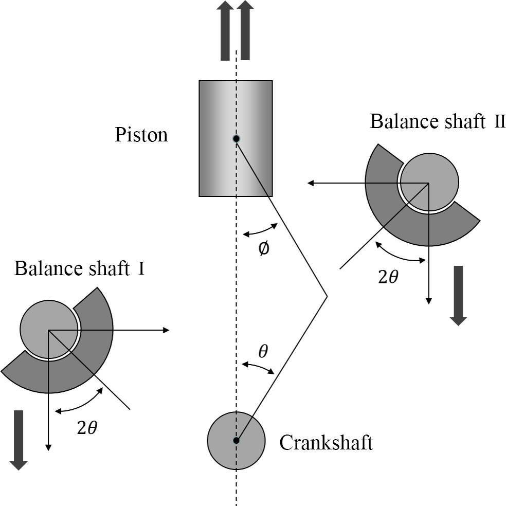
The simplified engine module kinematics including balance shaft module is described in Fig. 1 (Kim et al., 2012). To cancel out the second order vibration, it can be balanced by a pair of counter-rotating balance shafts at twice the angular velocity of the crankshaft.
The unbalance quantity is determined by the secondary inertia force induced by the given engine specification and the expression of unbalance quantity is denoted in Eq. (3) with respect to the relation in Eq. (4) as:
Here, mb and rb are the equivalent mass and radius of rotation in unbalance quantity, respectively. If the balance shaft module is simplified with single rotor model, the corresponding function (W) that is equivalent to the inertia force should be dependent on the rotating angle of crankshaft and thereby it can be formulated by the Eq. (5) as:
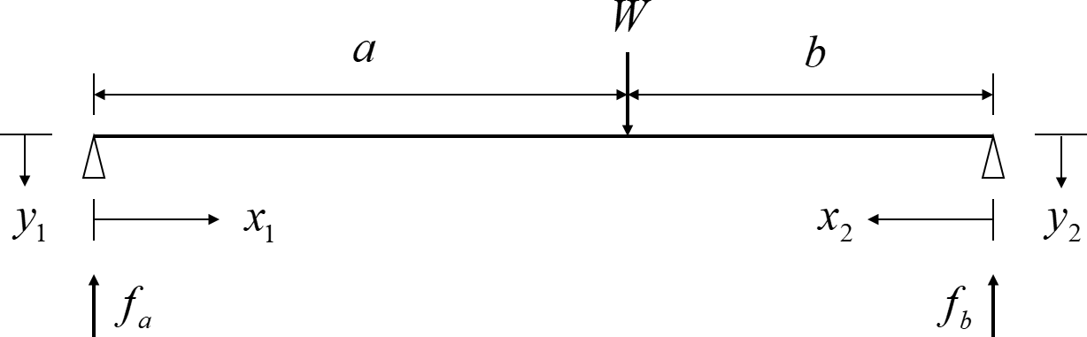
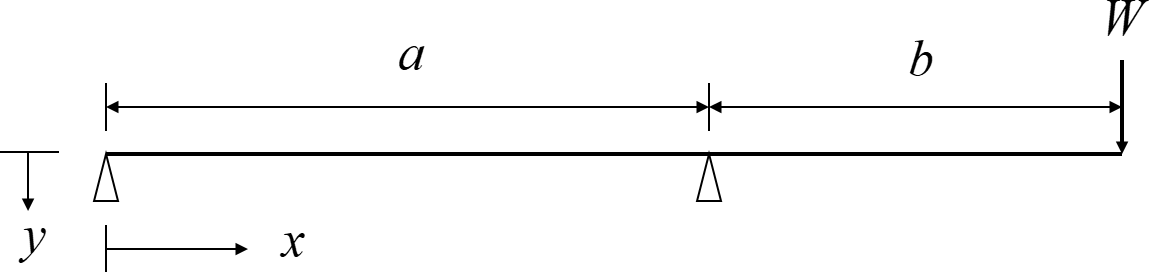
Using the Eq. (5), the corresponding bearing reaction force could be derived from the equivalent single rotor system shown in Fig. 2. The bearing reaction force at each location is formulated by the Eq. (5).
Here, a, b are positional variables regarding the position of the unbalance mass.
The bending case caused by inertia force between both sides of bearing is represented by Fig. 2. It could comprise the entire bending situation of inline 4-cylinder engine. Using the boundary condition of equivalent rotor model in Fig. 2, the corresponding deformation variable, y1,y2 could be formulated by Eqs. (7) and (8), respectively (Gere and Timoshenko, 1999). In addition, the total deflection of the balance shaft (y4c(x)) can be formulated with respect to the location of unbalance mass, x, as shown in Eq. (9).
Here, E is an elastic proportional coefficient, I is the second moment of inertia about the equivalent rotor's section and l is the total length of rotor system.
2.2 Inline 3-cylinder engine
With 120 (degree) firing interval, the primary and secondary inertia forces are balanced at the inline 3-cylinder engine. However, moments are not balanced in itself in the inline 3-cylinder engine and then, it needs a balance shaft module that produces moments with opposite phase. The primary moments (Mp) induced by the reciprocal inertia forces (see Eq. 1) can be written by Eq. (10) considering the overall geometry of engine module plotted in Fig. 3. The other moments are ignored here because primary term is dominant during operation as well as it is hard to balance other term simultaneously with single balance shaft module (Heisler, 1998; Stone and Ball, 2004; Suh et al., 2000).
The unbalance quantity (MB) is determined by the similar method in inline 4-cylinder engine (see Eq. 4) as:
Here, is length of balance shaft, mB, rB is equivalent mass and radius of unbalance, respectively. Hence the resultant quantity can be formulated as Eq. (12) as:
Since the balance shaft should be designed to make a primary moment without any inertia forces during rotating motion, two identical unbalance quantities locates in a opposite phase in a single rotor. The possible type of equivalent rotor with unbalance mass and bearing could be classified into three cases as shown in Fig. 4.
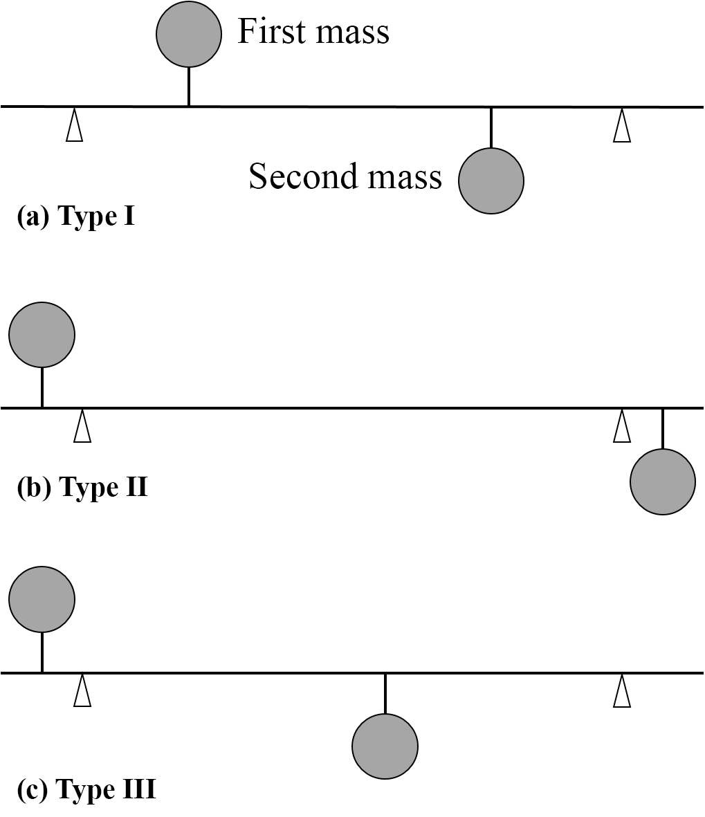
Figure 4Equivalent balance shaft model with bearing reaction in inline 3-cylinder engine (first bearing: black triangle, second bearing: white triangle).
Even though the type of equivalent rotor exists for three cases, the bearing reaction force (fC) against the given unbalance quantity has a unique expression in Eq. (13) as:
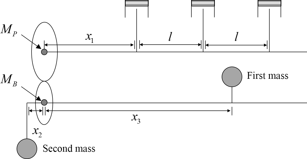
Here, Ls is a distance between each bearing and is a distance between each unbalance mass. The bending deformation in inline 3-cylinder is much complex than that of inline 4-cylinder one because it is possible to make several combinations of two unbalance masses under same moment as seen in Fig. 4. Requiring bending case which could not completely formulated by the previous bending case (see Eqs. 7 and 8) is determined by the ideal bending situation given in Fig. 5.
Here, W is inertia force induced at the edge of rotor. Given the inertia force and boundary condition, the corresponding deformation variable, y3, y4, is formulated by Eqs. (14) and (15), respectively (Gere and Timoshenko, 1999). In addition, the total length of the balance shaft (y3c(x1,x2)) at one-end unbalance can be derived with the both positions of supporting bearing, first at x3 and second at x4, as shown in Eq. (16).
Given the same inertia force or moment, it is recommended that the bearing reaction force should be kept minimal as long as one can. It is also suitable case if the bending deformation has a minimal value. However, the ideal situation which satisfies the minimal condition for both of items simultaneously is impossible in a physical view since the high level energy triggered from centrifugal force should be exhausted by bearing reaction force or bending deformation in order to remain the system stable. The optimal strategy on balance shaft is focused on trading off the inconsistent variables with unique weighting function for each problem, and finally, all the design parameters should not excess a guideline in design specification.
3.1 Inline 4-cylinder engine model
Considering the two inconsistent items, bearing reaction force and bending deformation, objective function is formulated to minimize the cost of both items within a single rotor model as assuming that both of items are state variables and the position variable, x, is design parameter as shown in Eq. (17). State variables are normalized to restrain the affection of physical magnitude to the result of objective function and the constraint of parameter variable is written in Eq. (18). Since the bearing reaction functions are function of rotation of crankshaft (see Eq. 5), current reaction force is considered at the maximum value (θ=nπ).
Here, A(x) and B(x) are state variables that denotes bending deformation (see Eq. 9) and difference between both of bearing reaction forces, respectively, and Lb is total length of given rotor. The variable, w, in a second term of Eq. (17) is weighting factor which is determined by the purpose of rotor design, i.e. “0” means the design is only focused on the minimal cost of bending deformation and “certain value much greater than 2” means opposite design condition, only considering the bearing reaction force. Hence, the value of w is generally assigned near “2” to consider all state variables except a special requirement in design specification.
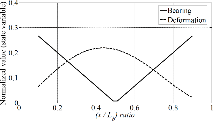
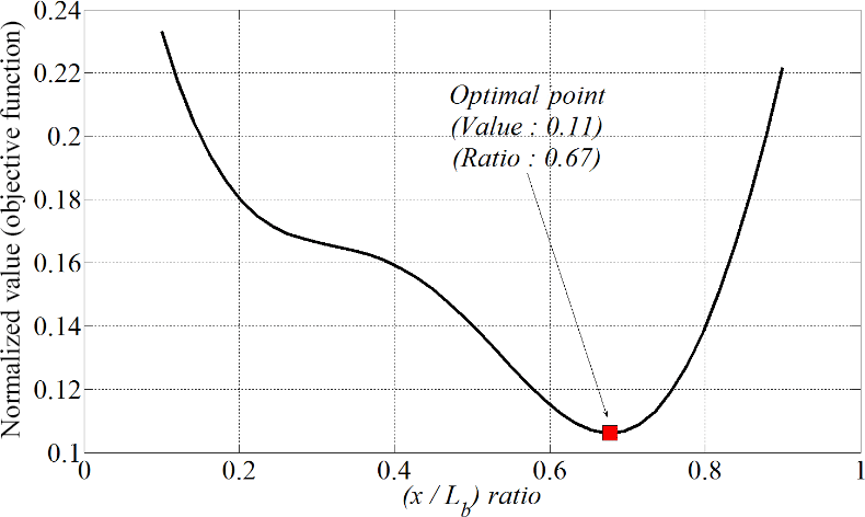
To verify the methodology of design strategy, the bearing reaction force and bending deformation is calculated in an equivalent rotor model in Fig. 2. The trace of two state variables are recorded as varying the design variable, x and the value of w is assigned for “2” in an objective function. The state variables and the corresponding objective function are obtained according to the value of x and then, all of normalized variables are plotted in Figs. 6 and 7, respectively.
The two state variables shows a conflicting trend as varying the position of unbalance mass from Fig. 6 and the proposed optimal function holds a global optimal point from Fig. 7. It can figure out that the optimal ratio of unbalance mass is 67 % in the total rotor length.
3.2 Inline 3-cylinder engine model
It is better to define a representative equivalent rotor model among three cases in Fig. 4 before formulating an optimal function owing to several design parameters are given on making an equivalent rotor model. Assuming that all of rotors have a same unbalance quantity, the “type III” model (see Fig. 5) is selected as the representative one under conducting an analysis afterward, because such a model is most widely used in a field situation.
Bending deformation and bearing reaction force can be satisfied simultaneously as being the most appropriate condition in a single rotor model, if the left bearing is approached to the left unbalance mass as well as the right bearing is positioned near the right unbalance bearing. The former case can be proven by the relation, “bending case I” and “bending case II” in Eqs. (12)–(13), and the latter can be made sense by the Eq. (11), given the same moment from a rotor model. However, the current model which seems to be optimal could bring out unintended situation by making the system unstable, because the structural bending stiffness in itself becomes minimal and then, it follows to clamp down the fundamental frequency as low as minimal.
During the general design process of balance shaft, it will focus on the shape optimization given the same unbalance quantity and the variation of structural stiffness is more vulnerable than that of structural mass. Hence, the fundamental frequency is a function of structural stiffness with little recognition of mass factor. Assuming that a balance shaft is simplified by a beam model, the structural stiffness can be expressed by the matrix shown in Eq. (20) and the corresponding element is given in Eq. (21) (Rao, 1983; Kramer, 1993).

Here, G, κ and l are elastic shear coefficient, shear coefficient and length of a beam, respectively. In Eq. (20), the first and third diagonal elements are the translational terms and second and forth diagonal elements are related to the rotational motion. Since the fundamental frequency was most sensitive to the first diagonal term (Kim, 2017), the element a1 is considered among several elements in stiffness matrix. Since both of variables, proportional elastic coefficient (E) and second moment of inertia (I) in section of beam, are constant, the resonance frequency (ω0) can be written by the Eq. (14) as:
Here, c is proportional coefficient. It can figure out from Eq. (22) that the resonance frequency is inverse proportional to the length of rotor and the corresponding rotor model is an unsatisfactory case for the issue of bending deformation and bearing reaction force. To tackle this problem in a preliminary step of rotor design, objective function is formulated in Eq. (23) with the boundary condition of variables in Eq. (24). Since both of items, bearing reaction force and bending deformation, have a similar tendency in a single rotor model, the variable on bearing reaction force is omitted under the formulation of objective function in Eq. (24) and the variable on resonance frequency is expressed using the equation in (25).
Here, c′ is proportional coefficient, y and z are the positions of first bearing and the second unbalance mass, respectively. In addition, C and D are state variables which represent the bending deformation and the fundamental resonance frequency, respectively. And w′ is the selecting factor that weights the degree of fundamental resonance frequency against the bending deformation. Hence, the bending deformation is only considered under the design process with the value of w′ is approaching zero and the situation turns opposite when w′ is far beyond of “2”. Without a special instruction in design specification, it is most accepted that the value of w′ is selected near “2” aiming for trade off both of issues at the same time.
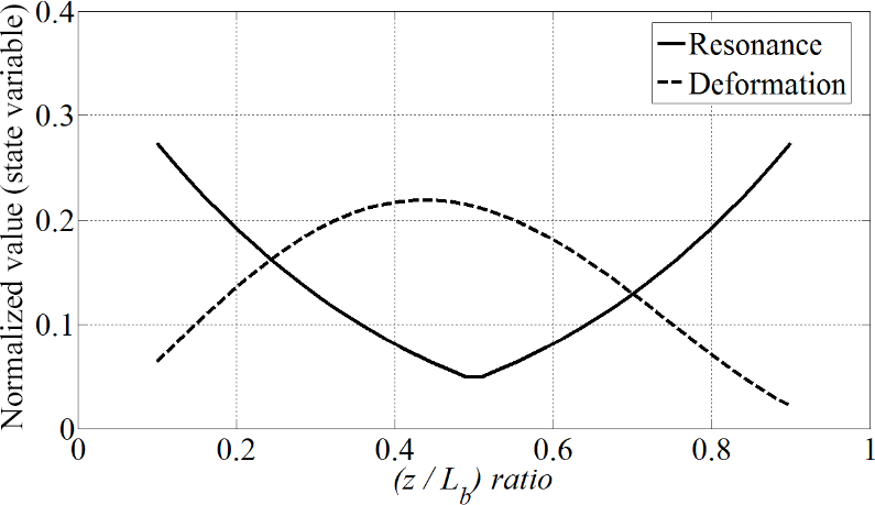
It is recorded the trace of objective function including state variables as varying the design variables. The position of first bearing is fixed (y=0) near the first unbalance mass since a large of bending deformation of rotor is expected near edge of rotor with first unbalance quantity (see Eq. 16). As varying the position of second unbalance mass, z, the trace of state variables in objective function are monitored and weighting factor, r′ is set to “2”. It is plotted the traces of items, both state variables and objective function, along the position of second unbalance mass in Figs. 8 and 9, respectively.
The both of state variables, bending deformation and fundamental resonance frequency, shows a opposite trend as varying the design variable (z) and such a combining of two state variables induces a global optimum in a proposed objective function. The optimal ratio of second unbalance mass position is 69 % in the total length of rotor.
4.1 Discussion
The optimal location of unbalance mass of the 4-cylinder engine was derived as 67 % in the total length of rotor and that result is similar derived from the previous study. As following the previous work (Kim et al., 2012), the location of unbalance mass was 57 % and 100 % in the total span of two supporting bearing if the capacity of one supporting bearing was supposed to be 80 % and 100 %, respectively. Here, the mass ratio between a symmetric part and an asymmetric part was selected for 3 or more. As following the optimal results from the previous job, the same optimal location of unbalance mass, 67 %, can expected approximately at 85 % if the linear relationship of optimal location is allowable.
However, the formulation of objective function in this study was somewhat different from the previous work. First, the current objective function were formulated from the rotor deflection and the difference of bearing force; whereas the elastic strain energy and the kinematic energy of the moment of inertia was applied in the previous study. This means the capacity of the supporting bearing was assumed to be originally limited one in this study so that both of supporting bearings should share the required inertia force from the inline 4-cylinder engine. So, if the capacity of supporting bearing was not sufficiently allowable over the required bearing force from an unbalance mass during operation, it is reasonable to accept the result from the proposed objective function. Second, the location of supporting bearing was fixed at the end of shaft length at current objective function; whereas considered as variable in the previous formula. The variation of the optimal location of supporting bearing was found to be less sensitive according to the different loading capacity of a supporting bearing (Kim et al., 2012), it is still reasonable to calculate of the optimal location of unbalance mass while the location of supporting bearing is fixed at certain location. So it can be revealed that the proposed optimal design strategy is efficient method for the balance shaft of 4-cylinder engine when the capacity of the supporting bearing was not fully allowable over the required bearing load.
The optimal location of unbalance masses of the balance shaft for 3-cylinder engine was not possible to discuss with previous studies. No previous works dealt with the optimal location of unbalance mass or supporting bearing in a balance shaft component. However, the optimal location of second unbalance mass at 69 % in the total length of rotor may be reasonable with the proposed objective function since a consistent objective function was developed by considering the nature of balance shaft in a 3-cylinder engine. The fundamental resonance frequency of a balance shaft is important issue in the 3-cylinder engine since at least one of unbalance mass is located at the end of rotor (see Fig. 4) as rule of thumb so that the fundamental frequency of balance shaft for 3-cylinder engine is far less than that for 4-cylinder engine. The proposed objective function was considered the stiffness of rotor system so that the dynamic issue from a 3-cylinder engine model was solved efficiently.
The optimal model of balance shaft derived in this study was definitely dependent on the type of combustion engine so that the conclusions for two different engine type will be changed if another type of combustion engine is considered. However, the proposed objective functions have capability to cope with both secondary inertia forces and moments, the calculation of optimal model of balance shaft still valid for another engine case under different magnitude of loading in Eq. (2) or in Eq. (10).
4.2 Optimal design process
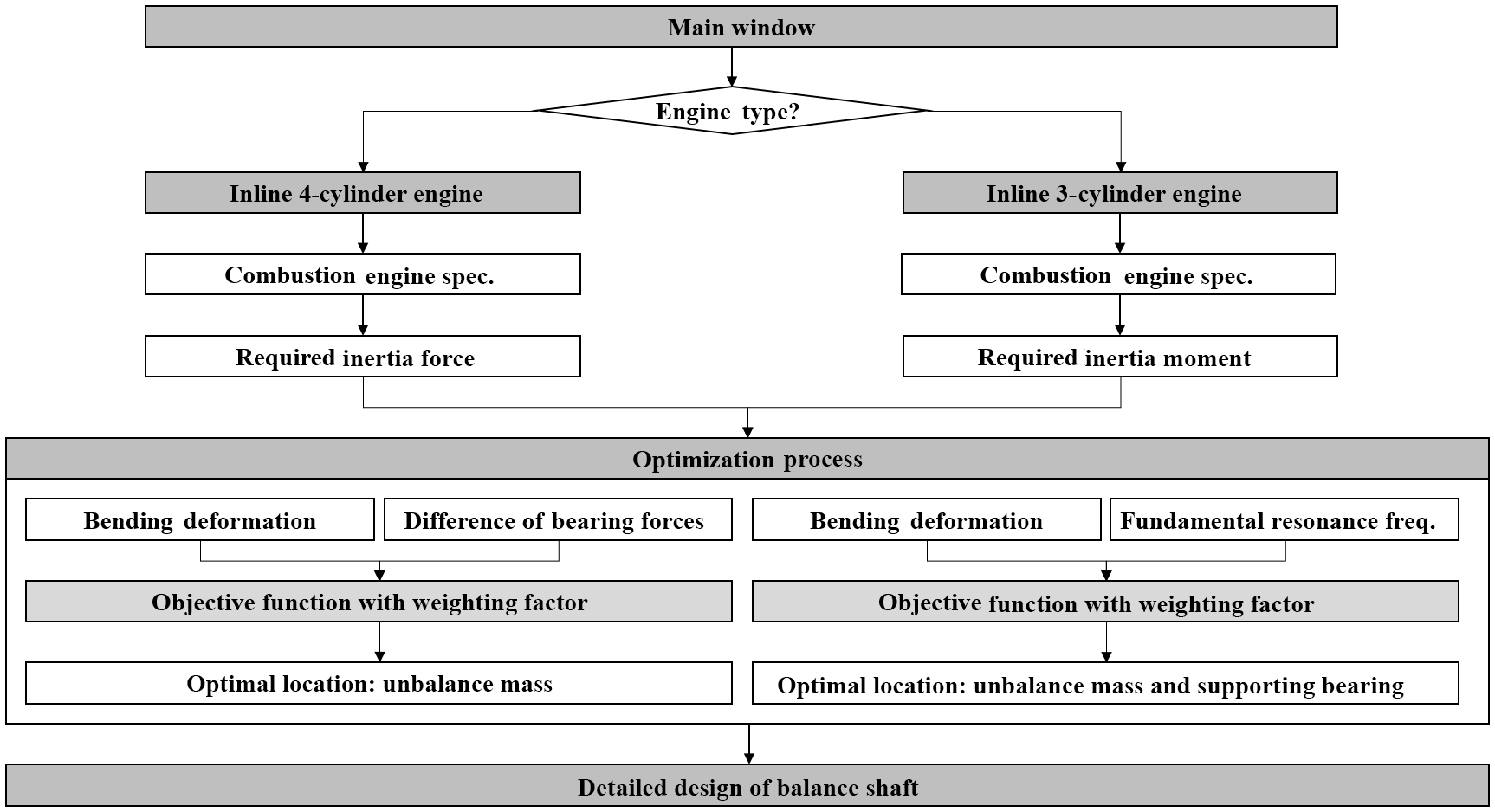
Applying for the fruit of research on balance shaft with efficiency, design program is developed as plugging the core formulation of optimal shaft design as well as other design parameters. After the equivalent rotor model is determined from the specification of corresponding engine module, the interesting state variables, like bearing reaction force and bending deformation, could be calculated according to the design variables. Especially, the optimal position of bearing and equivalent unbalance mass is predicted with the knowledge of optimal design formulation and it renders fundamental information on the proceeding of the detail design of balance shaft and its housing. The weighting of design parameters can be adjusted with weighting factor applied in objective function for two balance shaft. The overall optimal process of the balance shaft is explained for different engine type by the flow chart in Fig. 10.
Considering the total design process of balance shaft module, this study dealt with the preliminary step of balance shaft's design as how to locate the unbalance masses and corresponding bearings before the detail geometrical shape of balance shaft does not determined yet. It is selected for two cases of engine type, an inline 3-cylinder engine and an inline 4-cylinder one, and both of the required inertia force and moment were derived from the kinematic relationship between an engine and a balance shaft module. The equations related to the state variables were derived from the dynamics of the balance shaft as well as the basic beam theory and then, the objective functions were formulated using the related equations, which are bearing reaction force, bending deformation and fundamental resonance frequency. As following the simulation of balance shaft model, the proposed objective functions were confirmed to find global minimum that indicates the optimal locations of design parameters. Those optimal results are directly related to the conceptual design of the balance shaft for two different engine types. In particular, the optimal result of the inline 4-cylinder engine was compared with the result from previous study and it revealed the optimal position of the unbalanced mass at 67 % in total length was well matched with the previous results when the loading capacity of supporting bearing was set for approximately 85 %. Hence, the proposed optimal design strategies for two engine types were proven to be efficient one for the selection of both a supporting bearing and an unbalance mass. The design flowcharts of a balance shaft were illustrated in the final chapter to guide the determination of the optimal positions.
Data can be made available upon reasonable request. Please contact Chan-jung Kim (cjkim@pknu.ac.kr).
CJK is responsible for all technical steps from conceptual design, equation formulation, simulation and discussion.
The authors declare that they have no conflict of interest.
This work was supported by a Research Grant of Pukyong National University
(2017 year).
Edited by: Juan Andrés Gallego Sánchez
Reviewed by: Siavash Zamiran and two anonymous referees
Gere, J. M. and Timoshenko, S. P.: Mechanics of materials: Singapore, International Thomson Editores, 1999.
Hafidi, A. E., Martin, B., Loredo, A. and Jego, E.: Vibration reduction on city buses: Determination of optimal position of engine mounts, Mechan. Syst. Sig. Process., 24, 2198–2209, https://doi.org/10.1016/j.ymssp.2010.04.001, 2010.
Heisler, H.: Vehicle and Engine Technology: 2nd Edn., Warrendale, SAE International, 1998.
Huegen, S., Warren, G., and Menne, R.: A New 2.3L DOHC Engine with Balance Shaft Housing, Proceedings of SAE technical paper, 970921, https://doi.org/10.4271/970921, 1997.
Ishikawa, M., Nakamura, Y., Kodama, N., and Hosoi, H.: Development of resin gear balance shaft system for 2AZ-FE engine, JSAE Rev., 23, 27–32, https://doi.org/10.1016/S0389-4304(01)00164-3, 2002.
Kim, C. J.: Design sensitivity analysis of a Stockbridge damper to control resonant frequencies, J. Mechan. Sci. Technol., 31, 4145–4150, https://doi.org/10.1007/s12206-017-0810-0, 2017.
Kim, C. J., Kang, Y. J., Lee, B. H., and Ahn, H. J.: Determination of optimal position for both support bearing and unbalance mass of balance shaft, Mechan. Machine Theory, 50, 150–158, https://doi.org/10.1016/j.mechmachtheory.2011.11.006, 2012.
Kramer, E.: Dynamics of Rotors and Foundations: Berlin, Springer-Verlag, 1993.
Lin, D. Y., Hou, B. J., and Lan, C. C.: A balancing cam mechanism for minimizing the torque fluctuation of engine camshaft, Mechan. Machine Theory, 108, 160–175, https://doi.org/10.1016/j.mechmachtheory.2016.10.023, 2017.
Lui, X., Lv, Z., and Shangguan, W.: Design of power-train mounting system for engine with three cylinders, Proc. SAE technical paper, 2015-01-2354, https://doi.org/10.4271/2015-01-2354, 2015.
Meek, D. and Roberts, M.: Balance Shaft Conversion of a Four Cylinder Engine, Proc. SAE technical paper, 981084, https://doi.org/10.4271/981084, 1998.
Rao, J. S.: Rotor dynamics: Singapore, John Willey & Sons Inc, 1983.
Serrano, J. R., Guardiala, C., Dolz, V., Lopez, M. A., and Bouffaud, F.: Study of the turbocharger shaft motion by means of infrared sensors, Mechan. Machine Theory, 56–57, 246–258, https://doi.org/10.1016/j.ymssp.2014.11.006, 2015.
Shangguan, W. B., Liu, X. A., Lv, Z. P., and Rakheja, S.: Design method of automotive powertrain mounting system based on vibration and noise limitations of vehicle level, Mechan. Syst. Sig. Proc., 76–77, 677–695, https://doi.org/10.1016/j.ymssp.2016.01.009, 2016.
Stone, R. and Ball, J. K.: Automotive Engineering Fundamentals: Warrendale, SAE International, 2004.
Suh, K. H., Lee, Y. K., and Yoon, H. S.: A Study on the Balancing of the Three-Cylinder Engine with Balance Shaft, Proc. SAE technical paper, 2000-01-0601, https://doi.org/10.4271/2000-01-0601, 2000.