the Creative Commons Attribution 4.0 License.
the Creative Commons Attribution 4.0 License.
 | 20 Jul 2018
Analysis of Burr Formation in Low Speed Micro-milling of Titanium Alloy (Ti-6Al-4V)
Gulfam Ul Rehman
Syed Husain Imran Jaffery
Liaqat Ali
Ashfaq Khan
Shahid Ikramullah Butt
The use of titanium based alloys in aerospace and biomedical applications make them an attractive choice for research in micro-machining. In this research, low speed micro-milling is used to analyze machinability of Ti-6Al-4V alloy as low speed machining setup is not expensive and it can be carried out on conventional machine tools already available at most machining setups. Parameters like feed per tooth, cutting speed and depth of cut are selected as machining variables and their effect on burr formation is analyzed through statistical technique analysis of variance to determine key process variables. Results show that feed per tooth is the most dominant factor in burr formation (81 % contribution ratio). The effect of depth of cut was found to be negligible. It was also observed that micro-milling at optimum process parameters showed minimum burr formation. In terms of burr formation, as compared to high speed machining setup, better results were achieved at low speed machining setup by varying machining parameters.
- Article
(1860 KB) - Full-text XML
- BibTeX
- EndNote


Micro-machining is a process used for manufacturing miniaturized parts and features (Jaffery et al., 2016). Demand for highly precise and accurate micro components is rising day by day in the industries such as biomedical, aerospace, automotive and electronics (Chae et al., 2006; Jaffery et al., 2016; Kuram and Ozcelik, 2013). This miniaturization technology will provide micro systems to improve health care, quality of life and economic growth in such applications as micro channels for shape memory alloy “stents”, sub-miniature actuators and sensors, fluidic graphite channels for fuel cell applications, lab-on-chips and medical devices (Chae et al., 2006; Jaffery et al., 2016). There are a few unconventional machining processes which could be used to produce micro scale components such as focused ion beam cutting (Kuram and Ozcelik, 2013), micro-laser machining, micro-forming and micro electro-discharge machining (micro EDM) (Ucun et al., 2013) but these machining processes have limitations either because of producing two dimensional (2-D) microstructures or high costs of manufacturing/setup cost (Kuram and Ozcelik, 2013; Ucun et al., 2013). Other than these machining processes, micro-milling is another non-traditional machining technique which is capable of fabricating miniaturized three dimensional (3-D) complex parts/features (Ali et al., 2012; Özel et al., 2011; Thepsonthi and Özel, 2013). Although micro-milling is considered better than other non-traditional machining operations in terms of high material removal rate, process flexibility, low set up cost and producing complex shapes but it is also accompanied with some problems such as burr formation, low surface quality, unpredictable tool breakage and rapid tool wear (Özel et al., 2011; Thepsonthi and Özel, 2013). Therefore, many factors such as tool vibration (Jaffery et al., 2016; Thepsonthi and Özel, 2012), subsurface plastic deformation (Jaffery et al., 2016) and material microstructure (Thepsonthi and Özel, 2012) which are not taken into consideration at macro-level become significant at micro level (Thepsonthi and Özel, 2013) so, it becomes difficult to obtain desired results in micro-milling than that of macro-milling (Thepsonthi and Özel, 2012, 2013). Micro-milling becomes much more difficult when hard to cut materials are used for manufacturing such as Ti-6Al-4V titanium alloy (Thepsonthi and Özel, 2013). Ti-6Al-4V is known by the name “workhorse” of the titanium industry as it accounts for more than 45 % of actual titanium usage (Jaffery et al., 2016). It is widely used in biomedical (medical implants) (Thepsonthi and Özel, 2012), aerospace (turbine blades, aerospace fasteners) (Thepsonthi and Özel, 2012) and automotive (connecting rods, engine and exhaust valves) (Wagner and Schauerte, 2007) and marine industry (Ezugwu and Wang, 1997) due to its high strength to weight ratio (Bajpai et al., 2013; Ezugwu and Wang, 1997; Jaffery et al., 2016; Kim et al., 2014; Mhamdi et al., 2012; Thepsonthi and Özel, 2012), property to withstand high temperature (Ezugwu and Wang, 1997; Mhamdi et al., 2012), biocompatibility (Jaffery et al., 2016; Kim et al., 2014; Thepsonthi and Özel, 2012) and corrosion resistance (Ezugwu and Wang, 1997; Kim et al., 2014; Mhamdi et al., 2012; Thepsonthi and Özel, 2012). On the other side there are properties which make it difficult to cut material such as low thermal conductivity (Ezugwu and Wang, 1997; Kim et al., 2014; Mhamdi et al., 2012; Thepsonthi and Özel, 2012), high chemical reactivity (Ezugwu and Wang, 1997; Mhamdi et al., 2012) and low elastic modulus (Ezugwu and Wang, 1997). Syed Husain Imran Jaffery observed that tool wear increases during the machining of Ti-6Al-4V alloy due to high chemical reactivity of titanium with cutting tool material and low thermal conductivity which leads to tool fracture as most of the heat generated goes into the cutting tool (Jaffery and Mativenga, 2009).
Micro-milling seems to be a scale down machining operation of macro-milling but there are differences between these processes. In micro-milling, diameter of cutting tool (D) used is less than 1 mm while in macro-milling it is greater than 1 mm (Ali et al., 2012; Ducobu et al., 2009; Jaffery et al., 2016; Mian et al., 2010; Özel et al., 2011). In micro-milling, tool breaks quickly while in macro-milling tool wears gradually. Fracture of micro tools occur as stresses go beyond the strength of tools due to increase in cutting forces with the dulling of cutting edges (Tansel et al., 1998, 2000).
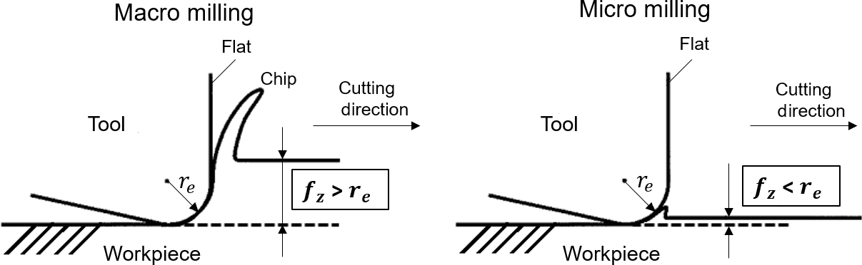
In macro-milling feed per tooth (fz) is many times larger than cutting tool edge radius (re) and in micro-milling feed per tooth is close to cutting tool edge radius (see Fig. 1) (Chae et al., 2006). Aamer Jalil Mian estimated minimum chip thickness (tm) in different materials by analyzing acoustic emission (AE) signals and found that for Ti-6Al-4V alloy, the value of minimum chip thickness ranges between 19 and 27.5 % of cutting tool edge radius (Mian et al., 2011a). Another researcher reported that the value of minimum chip thickness is between 5 and 38 % of cutting tool edge radius (Ducobu et al., 2009). Mohammad Yeakub Ali suggested that depth of cut is the most critical parameter to find out minimum chip thickness and to avoid tool fracture (Ali et al., 2012).
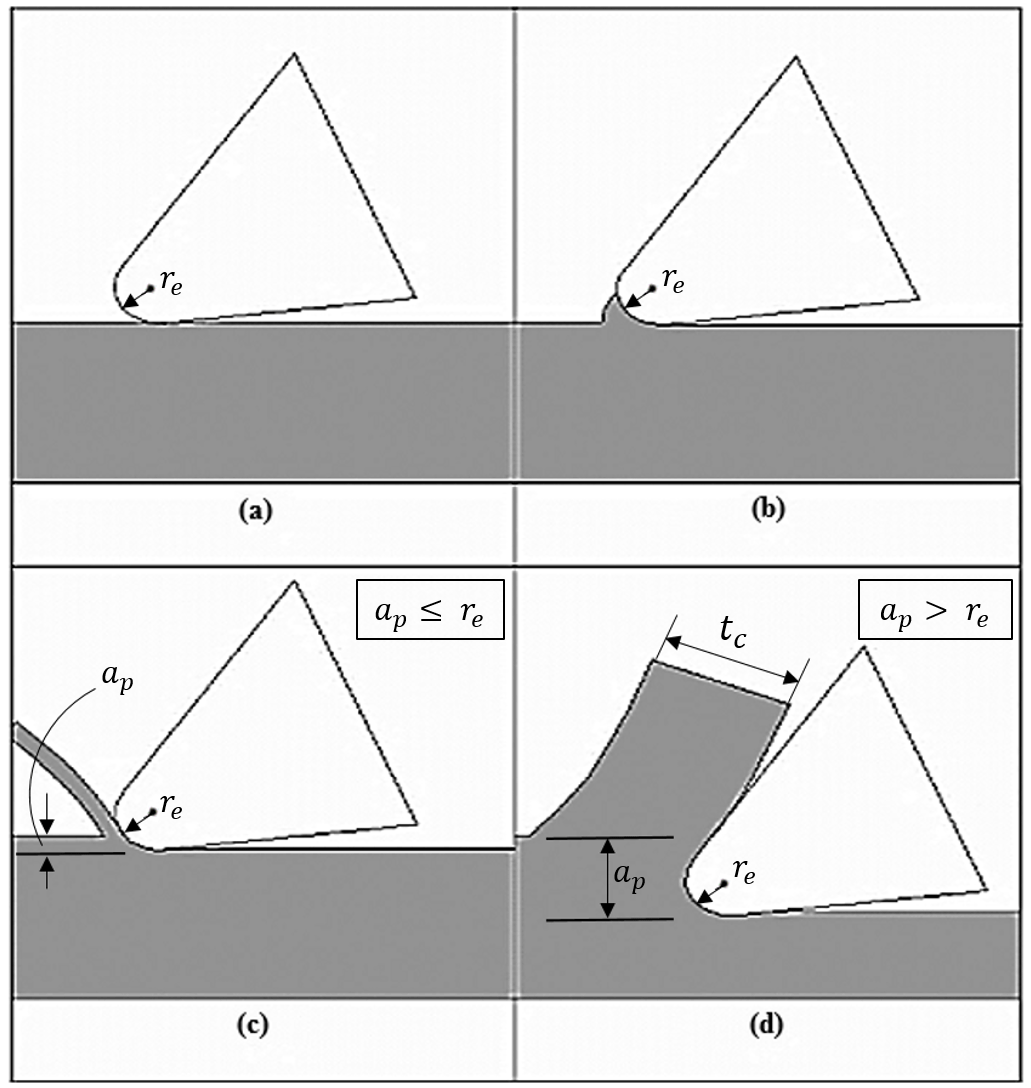
Figure 2 shows there are four situations that take place during the process of micro-milling. When depth of cut (ap) is smaller than cutting tool edge radius or minimum chip thickness either rubbing or burnishing occurs and no chip is formed (see Fig. 2a and b) (Jaffery et al., 2016). If the value of depth of cut reaches close to cutting tool edge radius or minimum chip thickness but still less than the edge radius of the cutting tool, ploughing starts. Ploughing is a phenomenon in which cutting takes place with negative effective rake angle or workpiece slightly deforms due to shearing of material (see Fig. 2c) (Ducobu et al., 2009; Jaffery et al., 2016). Once depth of cut becomes greater than the cutting tool edge radius then there is change of rake angle from negative to positive and actual cutting occurs (see Fig. 2d) (Jaffery et al., 2016).
Mechanical machining is always accompanied by burr formation either it is macro-machining or micro-machining. Deburring in macro-machining is easy as compared to micro-machining. In micro components, deburring may destroy delicate micro features as well as it can damage the workpiece. Moreover, cost of deburring process is very high as it requires complex assembly operation (Kim et al., 2014; Mian et al., 2010). Therefore, it is undesirable to use deburring process to remove burr and the recommended approach would be to select the appropriate machining parameters and tool geometry to reduce burr formation (Thepsonthi and Özel, 2012).
Syed H Imran Jaffery statistically analyzed the effect of feed rate (below and above cutting tool edge radius), cutting speed and depth of cut on burr formation in micro-machining of Ti-6Al-4V and found that feed rate was the most contributing factor causing burr formation and residual effects were more significant when feed rate was selected below edge radius (Jaffery et al., 2016). Tuǧrul Özel investigated the effect of cBN coated tools on burr formation and surface roughness in micro-milling of Ti-6Al-4V by varying process parameters and found that increasing feed rate reduced burr formation and cBN coated tools showed less burr formation than uncoated tools (Özel et al., 2011). Vivek Bajpai performed micro-milling experiments on Ti-6Al-4V alloy and observed that size of side exit burr was larger among all other burr types. It was also found that increase in chip load, cutting speed and depth of cut results in better surface finish (Bajpai et al., 2013). Aamer J. Mian conducted micro-milling experiments on AISI 1005 steel and AISI 1045 steel and determined that best surface finish was achieved when feed rate was just close to cutting tool edge radius (Mian et al., 2010). Gandjar Kiswanto studied the effect of machining parameters on surface roughness and burr formation in the micro-milling of Aluminum alloy 1100 and found that surface roughness increased by increasing feed rate and also concluded that in order to reduce the burr formation up milling cutting strategy should be used as down milling cutting strategy produces bigger and wavier burrs (Kiswanto et al., 2015). Kiha Lee investigated burr formation in micro-milling of aluminum and copper and found that for micro-milling tool, exit and entrance burr was bigger in size than macro milling, considering burr size to chip load ratio (Lee and Dornfeld, 2002). Kiha Lee also explained that tool wear relates with burr height and it is proportional to feed rate. Size effect also plays an important role in burr formation and with the increase in edge radius of the cutting tool larger burrs are produced (Lee and Dornfeld, 2005). Aamer Jalil Mian conducted micro-milling experiment on NiTi alloy and found that feed rate to undeformed minimum chip thickness is the most critical factor in reducing burr root thickness. At high values of chip load, cutting starts earlier as compared to low undeformed chip thickness, as a consequence of this, ploughing effect becomes less pronounced (Mian et al., 2011b). Ravi Lekkala analyzed the burr formation in micro end milling of Aluminum and Steel using experimental and theoretical techniques and reported that either in down milling or up milling, burr height increases with the decrease in number of flutes and cutting tool diameter and burrs formed in the case of stainless steel were larger than aluminum (Lekkala et al., 2011). Sinan Filiz investigated micro-machinability of copper 101 and found that feed rate is directly proportional to surface roughness and inversely proportional to burr formation and cutting speed is directly proportional to burr formation and at higher feed rates the process is dominated by shearing which results in decrease in burr formation as compared to ploughing (Filiz et al., 2007). Fengzhou Fang suggested that after defining cutting and other machine parameters; tool sharpness and undeformed chip thickness are the most critical factors to determine burr height (Fang and Liu, 2004).
The review of literature shows that burr formation in micro-machining of different materials has been studied extensively and most of the research done on micro-milling of Ti-6Al-4V alloy is in the region of high speed machining (10 000–90 0000 rpm) (Bajpai et al., 2013; Chen et al., 2012; Jaffery et al., 2016; Jaffery and Mativenga, 2009; Kim et al., 2014; Özel et al., 2011; Thepsonthi and Özel, 2012, 2013). However, no research has been reported on micro-milling of Ti-6Al-4V alloy below 10 000 rpm. The reason for this is that high speed machining setup provides better surface finish, high material removal rate and reduced cutting forces (Bajpai et al., 2013; Jaffery et al., 2016; Jaffery and Mativenga, 2009; Thepsonthi and Özel, 2012, 2013). On the other hand, low speed machining setup is not expensive and can be carried out on conventional machine tools already available at most machining setups. Moreover, researchers have reported that in high speed micro-milling of Ti-6Al-4V, burr formation is more effected by change in feed per tooth rather than cutting speed (Jaffery et al., 2016; Özel et al., 2011; Thepsonthi and Özel, 2012, 2013). Therefore, using carbide tools for micro-milling of Ti-6Al-4V, this study aims to find out effect of critical machining parameters namely, feed rate, depth of cut and low/conventional cutting speed below 10 000 rpm (Bajpai et al., 2013) on burr formation and use statistical technique to find out best combination of key process variables (KPVs) to minimize burr formation.
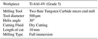
2.1 Workpiece material
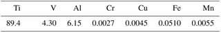
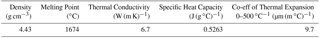
The material selected for experimentation is Ti-6Al-4V alloy. It is an alpha-beta (α+β) titanium alloy. This alloy comprises both alpha and beta phases with alpha phase ranges between 60 to 90 % and beta phase 10 to 40 % at room temperature. Alpha phase consists of hexagonal closed packing (HCP) structure that remains stable from room temperature while beta phase is characterized by body centered cubic structure (BCP) which keeps it stable from room temperature to melting point. There are stabilizer elements adding them would increase the transformation temperature of alpha and beta phase and therefore the stability of respective phase (Mhamdi et al., 2012). For example, adding aluminum, carbon, oxygen and nitrogen would increase the stability of alpha phase on the other side adding vanadium, molybdenum, manganese, chromium and iron would increase stability of beta phase (Banerjee and Williams, 2013; Machado and Wallbank, 1990; Zhecheva et al., 2005).
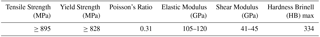
The chemical composition, mechanical properties and physical properties are given in the Tables 1, 2 and 3 respectively.
2.2 Experimental setup
The tests were conducted using a FANUC MV-1060 conventional speed machining center. Figure 3 shows experimental setup. Relative motion between micro end-milling tool and workpiece was controlled by FANUC 0i-MC motion controller. The tools used during micro-milling experiments of Ti-6Al-4V were ultrafine tungsten carbide tools (North Carbide Tools). The average edge radius of micro tools was found to be 4.0 µm with standard deviation of 0.5 µm. The dimensions of the block that was mounted on fixture were mm. Three independent runs for each experiment were run to estimate error variance. Experimental conditions are outlined in Table 4.
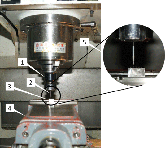
Figure 3Experimental Setup (1) Spindle; (2) Micro end mill; (3) Workpiece; (4) Machining vise; (5) Magnified view of tool and workpiece.
2.3 Design of experiment
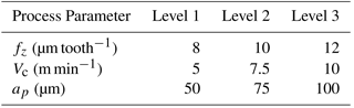
Micro-milling experiments were designed based on Taguchi's Design of Experiments. The array selected was L9 orthogonal array with three factors and three levels. Three independent factors of feed per tooth, cutting speed and axial depth of cut were considered. Syed H. Imran Jaffery in his research found that residual effects were more significant when feed per tooth was selected below tool edge radius (Jaffery et al., 2016). Therefore, to minimize the effect of residual effects feed rate was selected above tool edge radius between 8 and 12 µm tooth−1. In literature, reported cutting speed varies between 16 m min−1 (10 000 rpm) and 141 m min−1 (90 000 rpm) (Bajpai et al., 2013; Chen et al., 2012; Jaffery et al., 2016; Jaffery and Mativenga, 2009; Kim et al., 2014; Özel et al., 2011; Thepsonthi and Özel, 2012, 2013). While this research focuses on machining below the reported minimum cutting speed or in the range of conventional cutting speed below 10 000 rpm. Therefore, cutting speed was selected between 5 m min−1 (3183 rpm) and 10 m min−1 (6366 rpm). For every tool, according to its diameter, there is recommended value of ap to be used. According to Niagara Cutter (Cutter, 2018):
Therefore, in this research depth of cut was selected between 25–125 µm. Process parameters and level details are given in Table 5.
The spindle revolutions per minute (N) and feed speed (Vf) can be determined using the Eqs. (2) and (3) respectively.
Corresponding values of revolutions per minute and feed speed are listed in Table 6.
In micro-milling different types of burrs such as top burr, exit burr, entrance burr and bottom burr are formed depending on direction of cutting and tool-workpiece interaction (Aurich et al., 2009; Kiswanto et al., 2015). Exit burr and side burr is the burr which remains attach to the surface machined by minor cutting edge of the tool and major cutting edge of the tool respectively (Aurich et al., 2009). Top burr is the burr which remains attach to the top surface of workpiece (Aurich et al., 2009). During micro-milling process, chips generated move upward along the rake face of the cutting tool and the material that is in contact with the chips and workpiece pulls apart under large tensile stress. A part of this deformed material remains attach to the top surface and not taken away with the chips as a result of this top burrs are initiated (Chen et al., 2012). Figure 4 illustrates how top burr width is measured and it can be described as horizontal length of burr from groove wall (Thepsonthi and Özel, 2012). Table 6 shows results in the form of Taguchi orthogonal L9 array. Figure 5 shows burr formation on down milling and up milling side during micro-milling and it can be seen that size of burr is larger at down milling side. This is due to the fact that velocity of localized cutting edges on the side of up milling side would always be greater than on the side of down milling, therefore causing larger burrs to form on down milling side as also observed by Syed H Imran Jaffery (Jaffery et al., 2016). To account for worst case scenario down milling side burrs were taken into consideration. Maximum value of top burr width was measured for each run and to measure that scanning electron microscope (SEM) was utilized.
Table 6Taguchi orthogonal array (L9 array) for micro-milling of Ti-6Al-4V.
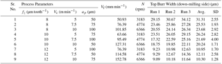

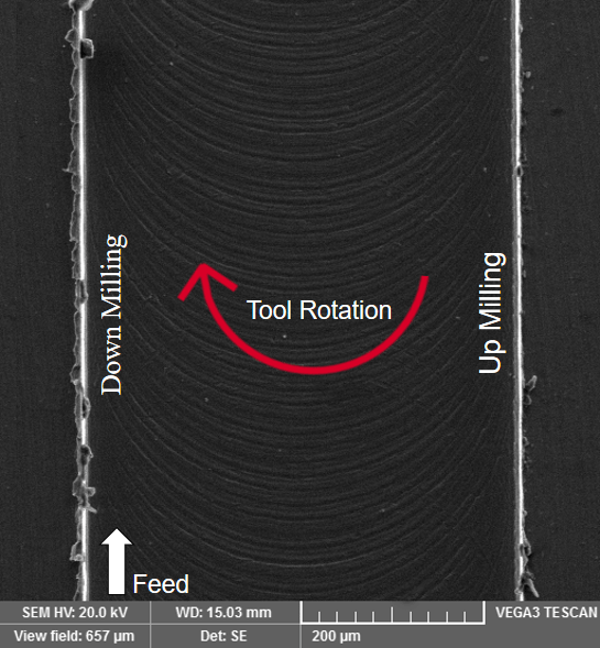
Figure 5Burr formation at down milling and up milling side during micro-milling of Ti-6Al-4V (fz=8 µm tooth−1, Vc=7.5 m min−1, ap=75 µm).
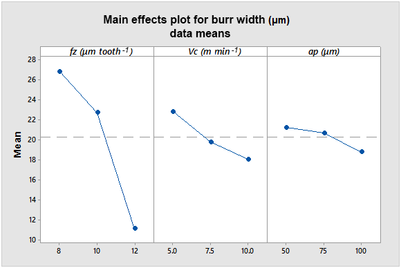
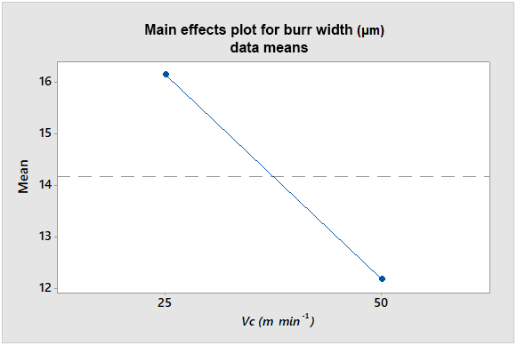
Figure 6Main effects plots for top burr width with respect to machining parameters (feed, speed and depth of cut).
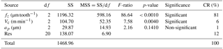
Table 7ANOVA table for significance and contribution ratio of parameters (feed, speed and depth of cut).
3.1 Application of ANOVA
After obtaining results of top burr width using SEM, ANOVA was used for statistical analysis of results. ANOVA is a statistical technique used to assess the significance of process parameters on output responses. This was performed by computing the sequential sum of squares (SSA) for each parameter using the Eq. (4).
Where A is the process parameter, n is the total number of runs at a particular level, i is the level, T is value of response at each run, j is the number of run, N is the total number of runs. Total sum of squares (SST) can be found using Eq. (5).
Sequential sum of squares of error (SSe) can be found using Eq. (6).
A small value of F-test ratio for a given parameter shows its low impact on the outcome and vice versa. A p-value is the probability that a test would fail. A p-value less than 0.05 (5 %) tells that there are 5 % chances that test would fail or 95 % chances that test would succeed. The percentage contribution of each parameter can be computed using Eq. (7).
3.2 Burr formation analysis
ANOVA was carried out to measure impact of parameters on burr width. From Table 7 it can be observed that feed per tooth is the most significant parameter contributing 81 % causing top burr formation and cutting speed is another parameter that is significant with contribution ratio of 6 % which shows that it has almost 93 % less impact on top burr as compared to feed per tooth. Each point in the main effects plot (see Fig. 6) shows mean or average top burr width for a particular level of feed rate, cutting speed and depth of cut. The CRs are comparable with a previous research in which similar analysis was conducted on Ti-6Al-4V alloy at high speed machining setup (Jaffery et al., 2016). From Fig. 6, it can be seen that top burr width decreases with the increase in feed per tooth. Researchers have reported similar outcomes from high speed micro-milling of Ti-6Al-4V alloy and found inverse relationship between feed rate and burr formation and concluded that feed per tooth is the most significant parameter influencing top burr formation (Jaffery et al., 2016; Kim et al., 2014; Thepsonthi and Özel, 2013). It is due to the fact that at lower feed per tooth, ploughing effect is more pronounced and material deforms plastically to form larger burrs (Kim et al., 2014).

Figure 7Main effect plot between fz∕re and top burr width (a) data from experiments; (b) data from Syed H. Imran Jaffery (Jaffery et al., 2016)
The ratio of feed rate to cutting tool edge radius (fz∕re) is also important in determining process performance whereby decrease in the value of feed per tooth below the cutting tool edge radius or grain size of the workpiece material would affect the material flow, chip formation and material deformation (Mian et al., 2011c). Taking cutting tool edge radius into consideration, Fig. 7a and b show the main effect plot created between fz∕re ratio and top burr width using data from experiments and Syed H. Imran Jaffery (Jaffery et al., 2016) respectively. By looking at burr formation trend in Fig. 7b it can be observed that when the value of feed per tooth is close to the value of edge radius or three times the value of edge radius, burr formation shows a downward trend. Burr generation increases when fz∕re is larger than 3 because below edge radius rubbing phenomenon is dominant and actual cutting takes place after the passage of several passes when the actual undeformed chip thickness crosses the threshold value for cutting to take place. When fz∕re is greater than 3, the ploughing action gives way to cutting leading to an increase in burr size. Ploughing action is expected to continue for value of fz∕re greater than 1 due to the formation of built-up edge and increase in the effective edge radius during the cutting process.
Comparing Fig. 7a and b, the region of fz∕re (2.0 to 3.0) from Fig. 7a lies within the region of Fig. 7b (0.9 to 3.0) and trend of burr formation with respect to feed rate is in conformance with the research conducted by Syed H. Imran Jaffery (Jaffery et al., 2016). Moreover, it can also be concluded that to reduce burr formation in micro-milling of Ti-6Al-4V, feed per tooth should be in the range of one to three times of cutting tool edge radius either it is high speed machining or low speed machining.
Main effects plots (see Fig. 6) for cutting speed and depth of cut also show a downward trend which means increase in cutting speed and depth of cut reduces the burr width. These result are comparable with the findings of research where similar analysis and experiments were performed on Ti-6Al-4V opting high speed machining (Bajpai et al., 2013; Jaffery et al., 2016; Kim et al., 2014; Thepsonthi and Özel, 2013). Increase in cutting speed is accompanied by decrease in cutting force (Jaffery and Mativenga, 2009; Pathak et al., 2013) and as cutting speed decreases contact time of tool with the chip is reduced.as a result less heat is transferred into the chip and more heat is transferred into the tool tip (Rosemar et al., 2013). Temperature in the shear zone is expected to rise at higher cutting speeds but the friction between the tool rake face and chip is reduced thereby reducing the welding phenomenon between chip and workpiece and heat generation at the tool chip interface (Prasad, 2009) as a result reduction in burr formation takes place. While it is also possible to minimize burr width by further increasing Vc (see Fig. 8) but this research aims to carry out micro-machining below 10 000 rpm using conventional machining setups that are more easily available and inexpensive as compared with high speed machining setup. In terms of depth of cut, at high depth of cut surface temperature decreases and most of the heat generated goes into the chips. To absorb more heat larger chips are produced which ultimately results into less burr formation (Prasad, 2009).
3.3 Confirmation test
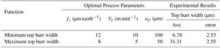
From main effects plot it can be seen that setting feed per tooth, cutting speed and depth of cut at high levels yielded minimum top burr width. So, a validation test was carried out for burr width selecting optimal levels of parameters. A summary of machining parameters and experimental results corresponding with best and worst operating conditions is given in the Table 8.
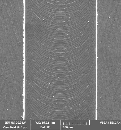
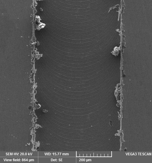
It is evident from presented results that optimum conditions yield best results as compared to the initial results reported in Table 6. Figure 9 shows negligible burr at optimum conditions and Fig. 10 shows maximum burr.
Identifying KPVs is very important to enhance product quality and at the same time productivity which ultimately leads to less manufacturing costs. The impact of machining parameters in micro-milling is not as same as in macro-machining. This is due to fact that feed rate is almost of the same order as edge radius of the cutting tool. In this paper, KPVs (feed per tooth, cutting speed and depth of cut) were varied to study their impact on burr formation in detail. ANOVA technique was applied on measured outputs to investigate the main effect of machining parameters on burr formation.
-
Machining at optimum conditions gave best outcome in the form of minimum burr on the edges of slot.
-
It is clearly evident that reduction in burr formation in micro-milling of Ti-6Al-4V can be effectively achieved by using low speed machining setup at optimal conditions instead opting for expensive high speed machining setup.
-
At 95 % confidence level, feed rate was found to be the most significant factor contributing towards burr formation with contribution ratio of 81 %.
-
Reduction in burr formation can be achieved by selecting feed per tooth in the range of 1–3 times of edge radius either it is low speed or high speed machining setup.
-
Cutting speed is another control factor affecting burr formation during micro-milling process and its contribution was found to be 6 % which is 75 % less than feed rate contribution.
-
The impact of depth of cut was negligible (1 % contribution ratio).
-
The contribution of residual effects was found to be 12 %. This is due to many noise factors i.e. subsurface plastic deformation, tool vibrations, chatter, material separation and strain hardening.
No data sets were used in this article.
| D | Diameter of cutting tool (mm) | CR | Contribution ratio (%) |
| fz | Feed per tooth (µm tooth−1) | Avg. | Average |
| re | Cutting tool edge radius (µm) | SD | Standard Deviation |
| tm | Minimum chip thickness (µm) | EDM | Electro Discharge Machining |
| ap | Depth of cut (µm) | 2-D | Two Dimensional |
| Vc | Cutting speed (m min−1) | 3-D | Three Dimensional |
| Vf | Feed speed (mm min−1) | AE | Acoustic Emission |
| N | Revolutions per minute (rpm) | KPVs | Key Process Variables |
| z | Number of flutes | α+β | Alpha-beta |
| SS | Sum of squares | HCP | Hexagonal Closed Packing |
| MSS | Mean sum of squares | BCP | Body-centered Cubic Packing |
| df | Degree of freedom | SEM | Scanning Electron Microscope |
GUR, SHIJ and MK designed experiments, GUR performed experiments supervised by LA on the CNC machine, AK and SIB reviewed drafted paper, suggested amendments and guidance during revisions.
The authors declare that they have no conflict of
interest.
Edited by: Bahman Azarhoushang
Reviewed by: two anonymous referees
Ali, M. Y., Khan, A. A., Banu, A., and Asharaf, M.: Prediction of Minimum Chip Thickness in Tool Based Micro End Milling, Int. J. Integr. Eng., 4, 6–10, 2012.
Aurich, J. C., Dornfeld, D., Arrazola, P. J., Franke, V., Leitz, L., and Min, S.: Burrs-Analysis, control and removal, Annals of the CIRP, 58/2, 519–542, https://doi.org/10.1016/j.cirp.2009.09.004, 2009.
Bajpai, V., Kushwaha, A. K., and Singh, R. K.: Burr Formation and Surface Quality in High Speed Micromilling of Titanium Alloy (Ti6Al4V), in: Volume 2: Systems; Micro and Nano Technologies; Sustainable Manufacturing, V002T03A017, ASME, 2013.
Banerjee, D. and Williams, J. C.: Perspectives on Titanium Science and Technology, Acta Mater., 61, 844–879, https://doi.org/10.1016/J.ACTAMAT.2012.10.043, 2013.
Chae, J., Park, S. S., and Freiheit, T.: Investigation of micro-cutting operations, Int. J. Mach. Tool. Manu., 46, 313–332, https://doi.org/10.1016/j.ijmachtools.2005.05.015, 2006.
Chen, M. J., Ni, H. B., Wang, Z. J., and Jiang, Y.: Research on the modeling of burr formation process in micro-ball end milling operation on Ti-6Al-4V, Int. J. Adv. Manuf. Tech., 62, 901–912, https://doi.org/10.1007/s00170-011-3865-6, 2012.
Cutter, N.: Speeds and Feeds, available at: http://www.niagaracutter.com/solidcarbide/speedfeed.html, last access: 16 July 2018.
Ducobu, F., Filippi, E., and Rivière-Lorphèvre, E.: Chip Formation and Minimum Chip Thickness in Micro-milling, Proc. 12th CIRP Conf. Model. Mach. Oper., 1, 339–346, 2009.
Ezugwu, E. O. and Wang, Z. M.: Titanium alloys and their machinability, J. Mater. Process. Tech., 68, 262–274, https://doi.org/10.1016/S0924-0136(96)00030-1, 1997.
Fang, F. Z. and Liu, Y. C.: On minimum exit-burr in micro cutting, J. Micromech. Microeng., 14, 984–988, https://doi.org/10.1088/0960-1317/14/7/020, 2004.
Filiz, S., Conley, C. M., Wasserman, M. B., and Ozdoganlar, O. B.: An experimental investigation of micro-machinability of copper 101 using tungsten carbide micro-endmills, Int. J. Mach. Tool. Manu., 47, 1088–1100, https://doi.org/10.1016/j.ijmachtools.2006.09.024, 2007.
Jaffery, S. I. and Mativenga, P. T.: Assessment of the machinability of Ti-6Al-4V alloy using the wear map approach, Int. J. Adv. Manuf. Tech., 40, 687–696, https://doi.org/10.1007/s00170-008-1393-9, 2009.
Jaffery, S. H. I., Khan, M., Ali, L., and Mativenga, P. T.: Statistical analysis of process parameters in micromachining of Ti-6Al-4V alloy, Proc. Inst. Mech. Eng. S., 230, 1017–1034, https://doi.org/10.1177/0954405414564409, 2016.
Kim, D. H., Lee, P.-H., and Lee, S. W.: Experimental Study on Machinability of Ti-6Al-4V in Micro End-Milling, Proc. World Congr. Eng., II, 1–4, 2014.
Kiswanto, G., Zariatin, D. L., and Ko, T. J.: The effect of spindle speed, feed-rate and machining time to the surface roughness and burr formation of Aluminum Alloy 1100 in micro-milling operation, J. Manuf. Process., 16, 435–450, https://doi.org/10.1016/j.jmapro.2014.05.003, 2015.
Kuram, E. and Ozcelik, B.: Multi-objective optimization using Taguchi based grey relational analysis for micro-milling of Al 7075 material with ball nose end mill, Meas. J. Int. Meas. Confed., 46, 1849–1864, https://doi.org/10.1016/j.measurement.2013.02.002, 2013.
Lee, K. and Dornfeld, D. A.: An Experimental Study on Burr Formation in Micro Milling Aluminum and Copper, in Proceedings of the North American Manufacturing Research Institution of the Society of Manufacturing Engineers, p. 8, 2002.
Lee, K. and Dornfeld, D. A.: Micro-burr formation and minimization through process control, Precis. Eng., 29, 246–252, https://doi.org/10.1016/j.precisioneng.2004.09.002, 2005.
Lekkala, R., Bajpai, V., Singh, R. K., and Joshi, S. S.: Characterization and modeling of burr formation in micro-end milling, Precis. Eng., 35, 625–637, https://doi.org/10.1016/j.precisioneng.2011.04.007, 2011.
Machado, A. R. and Wallbank, J.: Machining of Titanium and its Alloys—a Review, Proc. Inst. Mech. Eng. S., 204, 53–60, https://doi.org/10.1243/PIME_PROC_1990_204_047_02, 1990.
Mhamdi, M.-B., Boujelbene, M., Bayraktar, E., and Zghal, A.: Surface Integrity of Titanium Alloy Ti-6Al-4V in Ball end Milling, Phys. Procedia, 25, 355–362, https://doi.org/10.1016/j.phpro.2012.03.096, 2012.
Mian, A. J., Driver, N., and Mativenga, P. T.: A comparative study of material phase effects on micro-machinability of multiphase materials, Int. J. Adv. Manuf. Tech., 50, 163–174, https://doi.org/10.1007/s00170-009-2506-9, 2010.
Mian, A. J., Driver, N. and Mativenga, P. T.: Estimation of minimum chip thickness in micro-milling using acoustic emission, Proc. Inst. Mech. Eng. S., 225, 1535–1551, https://doi.org/10.1177/0954405411404801, 2011a.
Mian, A. J., Driver, N., and Mativenga, P. T.: Chip formation in microscale milling and correlation with acoustic emission signal, Int. J. Adv. Manuf. Tech., 56, 63–78, https://doi.org/10.1007/s00170-011-3185-x, 2011b.
Mian, A. J., Driver, N., and Mativenga, P. T.: Identification of factors that dominate size effect in micro-machining, Int. J. Mach. Tool. Manu., 51, 383–394, https://doi.org/10.1016/j.ijmachtools.2011.01.004, 2011c.
Özel, T., Thepsonthi, T., Ulutan, D., and Kaftanolu, B.: Experiments and finite element simulations on micro-milling of Ti-6Al-4V alloy with uncoated and cBN coated micro-tools, CIRP Ann.-Manuf. Technol., 60, 85–88, https://doi.org/10.1016/j.cirp.2011.03.087, 2011.
Pathak, B. N., Sahoo, K. L., and Mishra, M.: Effect of machining parameters on cutting forces and surface roughness in Al-(1-2) Fe-1V-1Si alloys, Mater. Manuf. Process., 28, 463–469, https://doi.org/10.1080/10426914.2013.763952, 2013.
Prasad, C. S.: Finite element modeling to verify residual stress in orthogonal machining, Blekinge Institute of Technology, Karlskrona, Sweden, available at: https://www.diva-portal.org/smash/get/diva2:830789/FULLTEXT01.pdf (last access: 16 July 2018), 2009.
Rosemar, B., Machado, Á. R., Ezugwu, E. O., Bonney, J., and Sales, W. F.: Tool life and wear mechanisms in high speed machining of Ti – 6Al – 4V alloy with PCD tools under various coolant pressures, J. Mater. Process. Tech., 213, 1459–1464, https://doi.org/10.1016/j.jmatprotec.2013.03.008, 2013.
Ross, P. J.: Taguchi Techniques for Quality Engineering, McGraw-Hill, New York, 1998.
Schaller, T., Bohn, L., Mayer, J., and Schubert, K.: Microstructure grooves with a width of less than 50 µm cut with ground hard metal micro end mills, Precis. Eng., 23, 229–235, https://doi.org/10.1016/S0141-6359(99)00011-2, 1999.
Tansel, I., Rodriguez, O., Trujillo, M., Paz, E., and Li, W.: Micro-end-milling – I. Wear and breakage, Int. J. Mach. Tool. Manu., 38, 1419–1436, https://doi.org/10.1016/S0890-6955(98)00015-7, 1998.
Tansel, I., Arkan, T., Bao, W., Mahendrakar, N., Shisler, B., Smith, D., and McCool, M.: Tool wear estimation in micro-machining, Int. J. Mach. Tool. Manu., 40, 599–608, https://doi.org/10.1016/S0890-6955(99)00073-5, 2000.
Thepsonthi, T. and Özel, T.: Multi-objective process optimization for micro-end milling of Ti-6Al-4V titanium alloy, Int. J. Adv. Manuf. Tech., 63, 903–914, https://doi.org/10.1007/s00170-012-3980-z, 2012.
Thepsonthi, T. and Özel, T.: Experimental and finite element simulation based investigations on micro-milling Ti-6Al-4V titanium alloy: Effects of cBN coating on tool wear, J. Mater. Process. Tech., 213, 532–542, https://doi.org/10.1016/j.jmatprotec.2012.11.003, 2013.
Ucun, I., Aslantas, K., and Bedir, F.: An experimental investigation of the effect of coating material on tool wear in micro milling of Inconel 718 super alloy, Wear, 300, 8–19, https://doi.org/10.1016/j.wear.2013.01.103, 2013.
Wagner, L. and Schauerte, O.: Status of titanium and titanium alloys in automotive applications, in: Ti-2007 Science and Technology, Proc. of the World Conf. on Titanium (JIMIC5), 3–7 June 2007, Kyoto, Japan, vol. 2, 1371–1378, 2007.
Zhecheva, A., Sha, W., Malinov, S., and Long, A.: Enhancing the microstructure and properties of titanium alloys through nitriding and other surface engineering methods, Surf. Coat. Tech., 200, 2192–2207, https://doi.org/10.1016/J.SURFCOAT.2004.07.115, 2005.