the Creative Commons Attribution 4.0 License.
the Creative Commons Attribution 4.0 License.
 | 17 Jul 2018
A modified ball screw lapping method and optimized lapping factors for ideal surface quality
Hutian Feng
Jun Jin
In order to meet the high precision requirement in various mechanical applications, ball screws are being lapped as a finishing process to improve the travel variation and surface quality. However, the existing manufacturing method is labor intensive. It depends on an operator's skill and experience and is very complex, time consuming with low production efficiency. The aim of this study is finding a modified lapping method to improve the lapping effect, increase efficiency and change the present labor-intensive situation. In addition, the effects of main lapping factors on the surface quality of a ball screw will be investigated, such as friction torque, rotational speed, abrasive particulate size and lapping time. A new lapping tool was installed on a specially designed friction torque test machine, which can control the rotation of a screw and monitor the friction torque applied on the screw dynamically. A set of orthogonal experiments were conducted on the test machine and the travel variation, surface roughness and residual stress of tested screws were measured after lapping. The measurement results of these three parameters were used to evaluate the lapping effect. Compared with the conventional lapping method, the lapping time of the present method was remarkably shorter, with only tens of minutes to get a good lapping result.
- Article
(2415 KB) - Full-text XML
- BibTeX
- EndNote


The ball screw mechanism has been used for many years. Ball screw is a force and motion transferring element that uses steel balls between a screw and a nut to convert rotary into linear motion when the screw rotates. Because of their advantages such as precise positioning and high efficiency, ball screw mechanisms are widely applied to feed-drive mechanisms of machine tools, robotics, metrology instruments and high-precision levelling platforms (Wei and Lin, 2004; Wei and Lai, 2011; Verl et al., 2014). In recent years, the demand of high precision ball screws increases rapidly. Ball screws must be produced with high degree of positioning precision. Generally, lapping is used as a finishing operation of the manufacturing process of ball screws to improve the travel variation and surface quality. Lapping is one of the surface machining processes. The abrasive particulates make a complex relative movement with the surface of a workpiece under the pressure of a lapping tool. The abrasive particulates will remove a very thin layer of material from the machined surface, which will improve the dimensional accuracy and surface quality of the workpiece. This operation does not demand a very high accuracy requirement of the equipment and is generally carried out under low speed and low-pressure conditions with much ease. Although lapping is effective for ball screws, the existing manufacturing method is very labor intensive that needs a highly skilled operator to perform the hand lapping operations using the conventional two- or three-slit lapping tool (Guevarra et al., 2001). It may take up to three months to obtain a ball screw with high precision. Further, the operator needs to be able to control and maintain the lapping condition, which relies entirely on his experience. It is very difficult with many uncontrollable factors.
Lapping ball screws for high precision is not a new method at all. However, only a few studies attempted to understand the process mechanism. Important contributions to the understanding of lapping performance are given by Kyusojin et al. (1979, 1984). They conducted the theoretical analysis of the cylindrical lapping with a new kind of lapping tool, which had lapping teeth moving in the radial direction. The results showed that lapping can rapidly decrease all components of any polygonal cross-sections. Based on this cylindrical lapping theory, Guevarra et al. (2001) designed a new lapping tool with 6 slits, which is different from the conventional 2-slit lapping tool. This new lapping tool has more contact areas with the workpiece to produce uniform lapping pressure from six directions, compared to the conventional tool which has only two pressure points. According to the experimental results, travel variation was greatly reduced. In another research, Guevarra et al. (2002) also built a prototyped horizontal lapping machine with in-process torque monitoring system to determine the relationship among lapping torque, effective diameter, and travel variation. The experimental results showed that there exists a very strong linear relationship among these three parameters, and a control system could be built based on this correlation as a new approach for high precision ball screw.
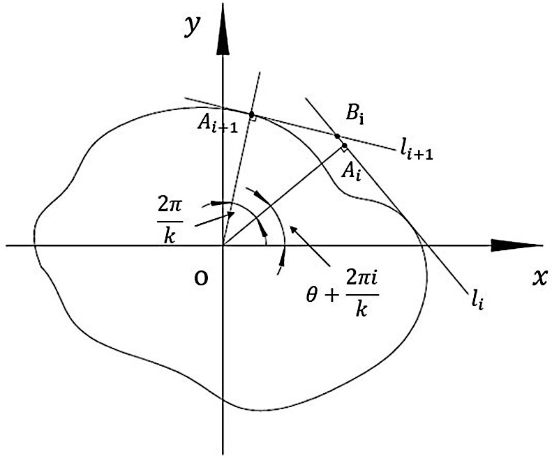
Figure 1Schematic diagram of the contact of the lapping tool with the external surface of the workpiece.
The aforementioned studies are useful in increasing lapping efficiency and meeting the requirements of modern manufacturing industry. However, there are still some deficiencies. Firstly, the screw they used was very small. The outside diameter of the screw was 14 mm, the lead was 2 mm and the length was only 260 mm. The size is much smaller than most screw sizes used in actual machine tools. Secondly, the performance parameters they used to evaluate the lapping effect were not sufficient. They only focused on the travel variation of tested ball screws, while other parameters, such as surface roughness and residual stress, have not been considered. Thirdly, different lapping factors have big influence on lapping effect, such as speed, abrasive particulate size and lapping time. It is essential to research the effect of these factors on lapping. In this study, a new lapping method was developed. In particular, a modified lapping tool was installed on a specially designed friction torque test machine, which can control the rotational speed and direction of a screw and monitor the friction torque applied on the screw dynamically. The effect of friction torque, rotational speed, abrasive particulate size and lapping time were analyzed based on the results of a set of orthogonal experiments. The travel variation, surface roughness and residual stress were measured to evaluate the lapping effect.
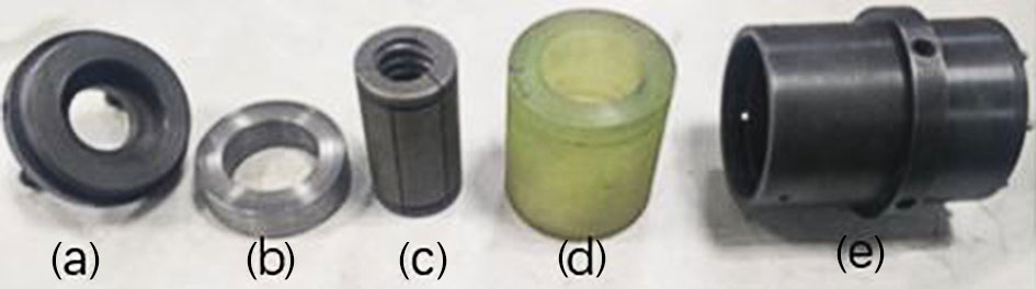
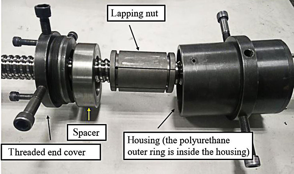
Figure 2Main parts of the lapping tool: (a) the threaded end cover; (b) the spacer; (c) the lapping nut; (d) the polyurethane outer ring; (e) the housing.
2.1 The structure of the lapping tool
For manual lapping operations, a traditional 2-slit lapping tool is used. The traditional lapping tool has two main disadvantages. Firstly, it demands specialized skills of the operator. In lapping a ball screw, high skills of the operator are definitely required, since the proper lapping condition particularly the lapping pressure and speed depend on his continuous adjustment of the operation. Secondly, the conventional lapping tool has two slits. When the screw is tightened, the lapping tool can create only two contact areas on the workpiece as the lapping progresses, and the center of the tool cannot coincide with the center of the workpiece. It can only make the workpiece into an ellipsoidal shape and therefore, difficult to attain the desired shape of a screw.
The modified lapping tool is based on the theory established by Kyusojin et al. (1979, 1984). The theory assumes that a lapping tool, which has a cross section in the form of a regular polygon (with k angles), is used to lap a workpiece and the tool is in contact with the external surface of the workpiece. The workpiece's radius r(θ) is given by tangent polar coordinate and can be represented by Fourier series:
(when ).
As shown in Fig. 1, li and li+1 are two sides of the lapping tool and the origin of the coordinate, o, is the workpiece center. Line oAi is the perpendicular of li. Similarly, line oAi+1 is the perpendicular of li+1. Bi(xi,yi) is the intersection of li and li+1. G(xG,yG) is used to express the center of the lapping tool when the tool rotates in contact with the external surface of the workpiece. Apparently, G(xG,yG) is the mean value of Bi(xi,yi). From Fig. 1,
li can be expressed as.
The coordinates of point Bi can be obtained by using Eqs. (2) and (3). Thus, xG can be obtained as
when condition, (m is an integer), is satisfied, xG≠0. It means that the center of the lapping tool and the center of the workpiece are not coincident. The expressions of xG and yG are given as follows:
The theory shows that the center of the workpiece must coincide with the center of the lapping tool to reduce the variation and increasing the number of slits is helpful. However, if the number of slits is too large, these two centers may be mismatched because of too much flexibility. Therefore, according to the reference and the lapping tool described by Guevarra et al. (2001), the new lapping tool has 6 slits and was designed to fit on the friction torque test machine.
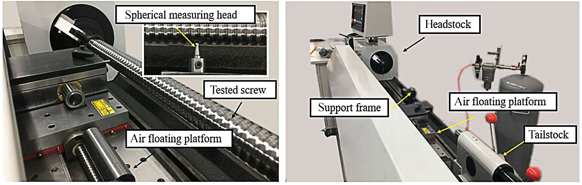
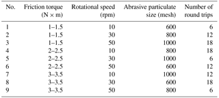
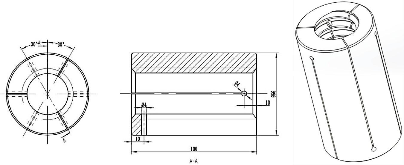
Figure 2 shows the details of the lapping tool. The lapping tool includes five parts: a threaded end cover, a spacer, a polyurethane outer ring, a housing and a lapping nut. The part named lapping nut has 6 slits consisting of 3 slits on each side which were cut alternately at 120∘ apart, as shown in Fig. 3. In order to prevent stress concentration, a through-hole was drilled in the end of each slit. This lapping tool has more contact areas on the screw to produce uniform lapping pressure from six directions, as compared to the conventional lapping tool which has only 2 slits. A polyurethane outer ring is used to cover the lapping nut. When the threaded end cover is screwed in the housing, the polyurethane outer ring will be compressed and provide stable friction torque during lapping. Changing the tightness of the end cover will change the friction torque applied on the screw.
2.2 The apparatus of the new lapping method
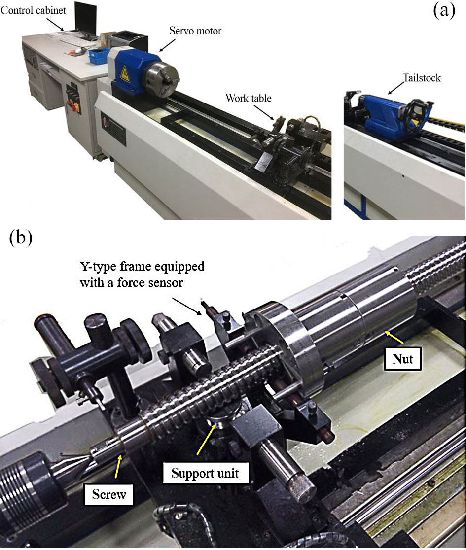
Lapping experiments were conducted on a specially designed, friction torque test machine. The structure of the test machine is shown in Fig. 4. The machine is installed with one end of a screw connected with the servo motor, and the other end fixed at the tailstock center. The ball screw can be driven by the servo motor, and the rotational speed can be set to different values according to different requirements. As shown in Fig. 4b, the support unit fixed on the work table is in contact with the screw so that the work table and the nut can move along the screw axis with the rotating screw. When the screw is driven by the motor, the friction torque of the ball screw will be transmitted to the Y-type frame which is equipped with a force sensor. The value of friction torque will be showed on the computer monitor dynamically. The new lapping tool should first be installed on a tested screw, just like a nut of the screw (as shown in Fig. 5) and then, the screw should be fixed on the test machine. The motor will drive the tested screw, while the lapping tool will move along the screw axis. The lapping process will be carried out by the reciprocate motion of the lapping tool on the screw.
A set of orthogonal experiments were designed to capture the effects of four main lapping factors: friction torque, abrasive particulate size, lapping time and the rotational speed of the screw. Details of each experiment are shown in Table 1. The lapping time was controlled by the number of round trips of the lapping tool. The lapping compound used was a mixture of green silicon carbide particulates and lubrication oil at about a volume ratio of 3:1. At the beginning of each lapping experiment, the compound was evenly brushed on the surface of the screw.
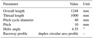
The travel variation, surface roughness, and residual stress were used to evaluate the lapping effect. Because it is very difficult to maintain the same travel variation among the screws during the test, even if they were acquired from the same manufacturer with the same process and size parameters, we customized 20 ball screws with the same parameters from the same manufacturer (the main parameters of the tested ball screw are shown in Table 2). The travel variations of all 20 ball screws were measured before lapping, and then 9 ball screws were picked, of which the initial values were very close to each other. Each screw had a non-lapping section at the end. The length of the section is 200 mm. The friction torque can be monitored by the test machine dynamically. When the fluctuation of friction torque exceeds the range of test parameter, the nut is considered to be worn out and will be replaced. When a lapping experiment was completed, the tested screw was cleaned and the travel variation was measured and then, the screw was cut to get sample pieces. The length of sample pieces is 80 mm. Each screw had two groups of sample pieces. One was from the lapping section, and the other from the non-lapping section. These pieces were used to measure the surface roughness and residual stress. The surface roughness and residual stress of the pieces from the non-lapping section will be used as the reference data in the subsequent analysis.

4.1 Travel variation
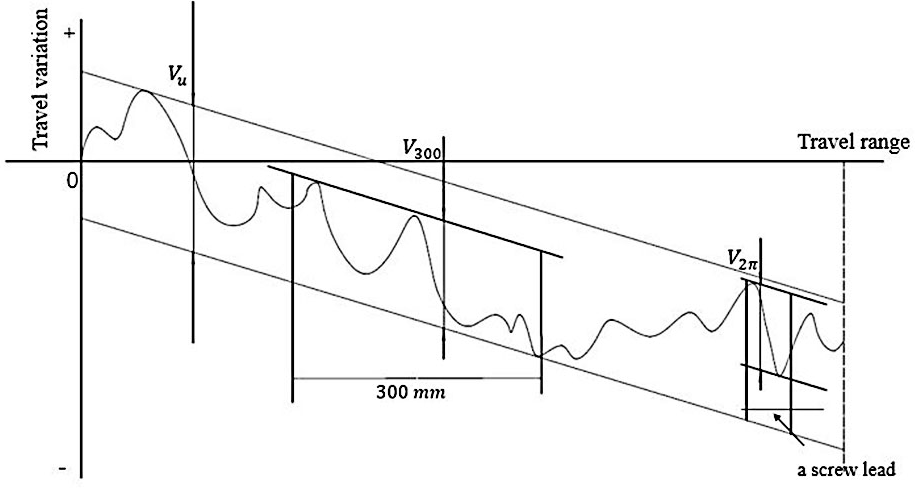
Tests to measure the travel variation were carried out on a ball screw test machine equipped with a circular grating and a linear grating. The structure of the test machine is shown in Fig. 6. The tested ball screw was fixed between the headstock and the tailstock. The spherical measuring head was placed in the screw raceway so that the air floating platform can move with the rotating screw. In travel variation measurement, there are three relevant indices (as shown in Fig. 7): the travel variation in a screw lead (V2π), which reflects the short-period error; the travel variation in arbitrary 300 mm (V300), which reflects the long-period error; and the travel variation in total effective travel (Vu), which reflects the gradual error. Comparing pulse signals measured from the circular grating and the linear grating determines these precision-related indices.
The index Vu is used in this study. Each screw was measured three times. Table 3 shows the measurement results of the travel variation. The average of the three measurement results of each screw was denoted by . denotes the average value before lapping. Four lapping factors including friction torque, rotational speed, abrasive particulate size, and lapping time were numbered from 1 to 4 (denoted by j, ), respectively. Each factor takes three different values which were number from 1 to 3. K1j denotes the sum of of the jth factor under value 1. For example, . denotes the average value of K1j.
The meanings of K2j, K3j, and are similar to K1j and . Rj denotes the difference between the maximum and minimum in , and . The larger the value of Rj, the greater the impact of this factor on the travel variation after lapping.
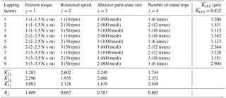
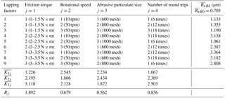
As shown in Table 3, is the minimum of , and . In addition, and are less than , while is much larger than , implying that a lower friction torque can improve the travel variation of the screw. In the second column (j=2), is the minimum and is less than . is the maximum, and is slightly smaller than . The tested ball screws lapped under 50 rpm have the smallest travel variation. In the third column (j=3), is the minimum, while and are very close to each other with slightly larger than . The results show that the 800 mesh abrasive particulates can result in the smallest travel variation. The three values in the fourth column (j=4), , and , are almost equal, of which is the smallest, while is in the middle with slightly larger than . In the last row of the table, R1 is the biggest of the four numbers R1, R2, R3 and R4, indicating that friction torque has the greatest effect on travel variation. R2 and R3 are almost equal and much less than R1. Compared with the friction torque, the rotational speed and abrasive particulate size have little effect on the resulted travel variation. As R4 is the smallest and therefore, the effect of lapping time on travel variation is negligible.
4.2 Surface roughness
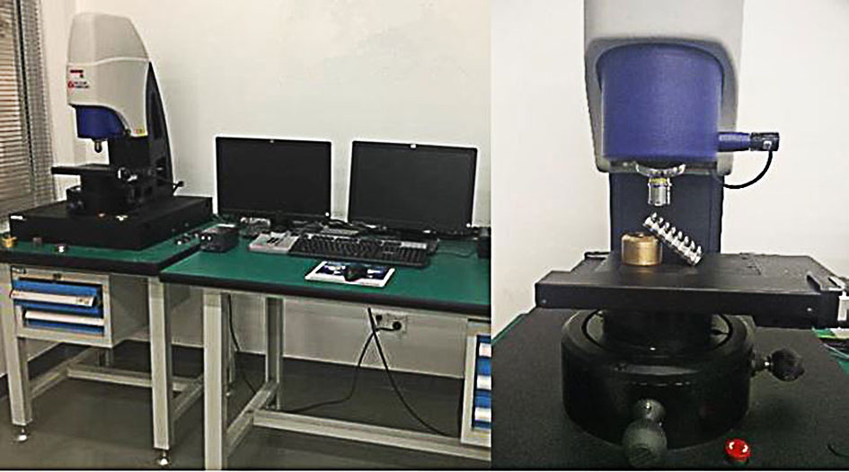
A Taylor Hobson CCI(UK) white light interferometer was used to measure the surface roughness, as shown in Fig. 8. Each sample piece of the tested screw after lapping has three roughness measurement points evenly distributed in the axial direction 120∘ apart. The left and right arcs of each point were measured. For the left arc, the average value of three points of each screw was denoted by , and for the right arc, it was denoted by . and denote the average values of the left and right arcs before lapping, respectively.

As shown in Table 4, all nine results, ∼ , are bigger than , indicating that the surface roughness getting worse inevitably after lapping. Whatever experimental parameters were used, the surface roughness became worse. In the first column (j=1), is the minimum, while is in the middle and is the largest. The increase in the friction torque increases the surface roughness. The results in the fourth column (j=4) is similar to the results in the first column. is the minimum followed by , and is the largest. The increase of lapping time causes the increase of surface roughness. In the third column (j=3), is the minimum, where and are slightly bigger than . The smallest abrasive particulates do not make the surface roughness too bad. In the second column (j=2), the difference among , and is very small. and are slightly larger than . In the last row of the table, R1 is the biggest of the four. Similar to the results of travel variation, the friction torque has the greatest effect on the resulted surface roughness. The values of R2, R3 and R4 are very close, while R2 is slightly smaller than R3 and R4. The same conclusions can be obtained from the results of the right arc, except that R3 is the smallest of the four.
4.3 Residual stress
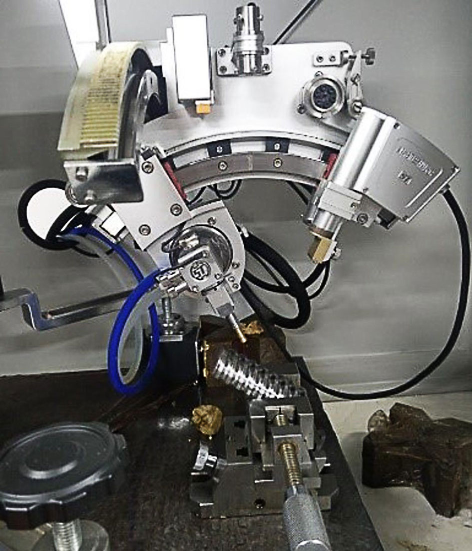
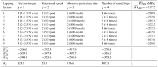
The X-ray stress measurement device, X-350A, was used to measure the surface residual stress, as shown in Fig. 9. The measurement points for residual stress were the same as for surface roughness. The left and right arcs of each point were measured. For the left arc, the average value of three points of each screw was denoted by ) and for the right arc, it was denoted by ). and denote the average values of residual stress of the left and right arcs before lapping, respectively.
As shown in Table 6. all nine results, ∼ , are smaller than . Moreover, they are less than zero, which indicates that the surface of the sample was in compressive stress state. According to the references (El-Axir, 2002; Rech and Moisan, 2003; Segawa et al., 2004; Sasahara, 2005), a residual compressive stress improves component performance and life because it reduces working tensile stress and inhibits crack nucleation, whereas residual tensile stresses can significantly increase working stress, and leading to premature failure of a component. Therefore, no matter what experimental parameters were used, the residual compressive stress of all samples was promoted. In the table, is the minimum (absolute value) in the first column (j=1) and is the maximum, which indicates that the higher the friction torque, the higher the residual compressive stress is. The second column (j=2) shows is the maximum and is the minimum. In the third column (j=3), the absolute value of is the minimum and is the maximum, which implies the bigger the abrasive particulate size, the higher the residual compressive stress is. In the fourth column (j=4), the absolute value of is the minimum while is the maximum, which indicates increasing the lapping time can increase the residual compressive stress. In the last row of the table, R3 is the largest of the four, while R1 is the second, and R2 is the smallest. Different from the conclusions mentioned above, the abrasive particulate size has greater effect on residual stress than friction torque or lapping time. The effect of the rotational speed is not as the important as the other three factors. The same conclusions can be obtained according to the results of the right arc.
In this study, a modified ball screw lapping method was proposed. The lapping tool was installed on a specially designed friction torque test machine. Compared with conventional lapping method, the lapping time of the present method was remarkably shortened, with only tens of minutes to get a good lapping result. Besides, this lapping method is more reliable as it doesn't rely on operators' experience and skills. The present method can help lower the labor cost and improve the efficiency of lapping.
Different values of lapping factors will bring about different lapping results. In this study, a set of orthogonal experiments was designed. The effects of lapping factors, including friction torque, rotational speed, abrasive particulate size and lapping time, were analyzed. The travel variation, surface roughness and residual stress of tested ball screws were measured to evaluate the lapping results. The following conclusions were drawn from the experimental results:
-
The travel variations of some of the tested screws were improved whereas others became worse with different lapping parameters. The surface roughness became worse no matter what experimental parameters were used. The results of residual stress of all nine ball screws were less than zero and higher than the initial compressive residual stress in magnitude, implying that the residual compressive stress was enhanced in each screw.
-
As shown in Table 3, R1 is much bigger than the other three, and therefore friction torque has the greatest effect on travel variation. The increase in the friction torque increases the travel variation of the screw. Compared with the friction torque, the rotational speed and abrasive particulate size have secondary effect on travel variation, whilst the effect of lapping time is negligible. If only the travel variation is concerned, the best combination of lapping parameters is 1–1.5 N × m, 50 rpm, 800 mesh and 12 round trips.
Similar to the results of travel variation, the friction torque has a dominant effect on the surface roughness, while the rotational speed, abrasive particulate size and lapping time have a secondary effect on surface roughness. The increase in the friction torque increases the surface roughness of the screw. If only the surface roughness is concerned, the best combination of lapping parameters is 1–1.5 N × m, 30 rpm, 1000 mesh and 6 round trips.
The abrasive particulate size has the greatest effect on residual stress, while the friction torque is the second and the lapping time is the third. The bigger the abrasive particulates, the higher the residual compressive stress is. Further, increasing the friction torque and lapping time can also improve the residual compressive stress. The influence of rotational speed is much less than the other three. If only the residual stress is concerned, the best combination of lapping parameters is 3–3.5 N × m, 30 rpm, 600 mesh and 18 round trips.
-
The friction torque has much larger effect on travel variation and surface roughness than the other factors. In particular, the increase in friction torque causes significant increase in travel variation of the screw and therefore, the optimum value of the friction torque is 1–1.5 N × m in order to minimize travel variation.
The rotational speed is not an important factor for travel variation, surface roughness and residual stress.
The abrasive particulate size has the greatest effect on residual stress. The 600 mesh abrasive particulates can significantly improve the residual compressive stress. Although 600 mesh is not the best choice for travel variation and surface roughness, the abrasive particulate size is not an important factor for them. Therefore, 600 mesh is suggested as the best particulate size for lapping.
The longer the lapping time, the worse the surface roughness is, whereas although a long time lapping process can improve the residual stress. Given that the lapping time is more important for residual stress rather than for surface roughness, and the surface roughness can be improved by subsequent processing, 18 round trips is suggested as the best choice for lapping.
No data sets were used in this article.
ZL, FH and JJ designed the modified lapping method and the lapping tool; ZL and JJ designed and carried out experiments; ZL and JJ collected and analyzed experimental results; ZL wrote the manuscript with contributions from all co-authors.
The authors declare that they have no conflict of interest.
Authors greatly thank Key Laboratory of Performance Test and Reliability
Technology for CNC Machine Tool Components of Chinese Machinery Industry to
provide test machines and experiment materials.
Edited by: Bahman Azarhoushang
Reviewed by:
three anonymous referees
El-Axir, M. H.: A method of modeling residual stress distribution in turning for different materials, Int. J. Mach. Tool. Manu., 42, 1055–1063, https://doi.org/10.1016/s0890-6955(02)00031-7, 2002.
Guevarra, D. S., Kyusojin, A., Isobe, H., and Kaneko, Y.: Development of a new lapping method for high precision ball screw (1st, report)-feasibility study of a prototyped lapping tool for automatic lapping process, Precis. Eng., 25, 63–69, https://doi.org/10.1016/s0141-6359(00)00059-3, 2001.
Guevarra, D. S., Kyusojin, A., Isobe, H., and Kaneko, Y.: Development of a new lapping method for high precision ball screw (2nd report): Design and experimental study of an automatic lapping machine with in-process torque monitoring system, Precis. Eng., 26, 389–395, https://doi.org/10.1016/s0141-6359(02)00122-8, 2002.
Kyusojin, A. and Inada, H.: Lapping high precision polygonal shafts, Precis. Eng., 6, 3–8, https://doi.org/10.1016/0141-6359(84)90064-3, 1984.
Kyusojin, A., Nishimoto, K., Kubota, S., and Moriyama, Y.: Development of the lap for correcting cylindrical axes, Int. J. Jpn. Soc. Precis. Eng., 45, 913–918, https://doi.org/10.2493/jjspe1933.45.913, 1979.
Rech, J. and Moisan, A.: Surface integrity in finish hard turning of case-hardened steels, Int. J. Mach. Tool. Manu., 43, 543–550, https://doi.org/10.1016/s0890-6955(02)00141-4, 2003.
Sasahara, H.: The effect on fatigue life of residual stress and surface hardness resulting from different cutting conditions of 0.45 % C steel, Int. J. Mach. Tool. Manu., 45, 131–136, https://doi.org/10.1016/j.ijmachtools.2004.08.002, 2005.
Segawa, T., Sasahara, H., and Tsutsumi, M.: Development of a new tool to generate compressive residual stress within a machined surface, Int. J. Mach. Tool. Manu., 44, 1215–1221, https://doi.org/10.1016/j.ijmachtools.2004.03.010, 2004.
Verl, A., Frey, S., and Heinze, T.: Double nut ball screw with improved operating characteristics, CIRP Ann., 63, 361–364, https://doi.org/10.1016/j.cirp.2014.03.128, 2014.
Wei, C. C. and Lai, R. S.: Kinematical analyses and transmission efficiency of a preloaded ball screw operating at high rotational speeds, Mech. Mach. Theory, 46, 880–898, https://doi.org/10.1016/j.mechmachtheory.2011.02.009, 2011.
Wei, C. C. and Lin, J. F.: Kinematic analysis of the ball screw mechanism considering variable contact angles and elastic deformations, J. Mech. Des., 125, 717–733, https://doi.org/10.1115/1.1623761, 2004.