the Creative Commons Attribution 4.0 License.
the Creative Commons Attribution 4.0 License.
 | 28 May 2018
Worm gear efficiency model considering misalignment in electric power steering systems
Seong Han Kim
This study proposes a worm gear efficiency model considering misalignment in electric power steering systems. A worm gear is used in Column type Electric Power Steering (C-EPS) systems and an Anti-Rattle Spring (ARS) is employed in C-EPS systems in order to prevent rattling when the vehicle goes on a bumpy road. This ARS plays a role of preventing rattling by applying preload to one end of the worm shaft but it also generates undesirable friction by causing misalignment of the worm shaft.
In order to propose the worm gear efficiency model considering misalignment, geometrical and tribological analyses were performed in this study. For geometrical analysis, normal load on gear teeth was calculated using output torque, pitch diameter of worm wheel, lead angle and normal pressure angle and this normal load was converted to normal pressure at the contact point. Contact points between the tooth flanks of the worm and worm wheel were obtained by mathematically analyzing the geometry, and Hertz's theory was employed in order to calculate contact area at the contact point. Finally, misalignment by an ARS was also considered into the geometry.
Friction coefficients between the tooth flanks were also researched in this study. A pin-on-disk type tribometer was set up to measure friction coefficients and friction coefficients at all conditions were measured by the tribometer.
In order to validate the worm gear efficiency model, a worm gear was prepared and the efficiency of the worm gear was predicted by the model. As the final procedure of the study, a worm gear efficiency measurement system was set and the efficiency of the worm gear was measured and the results were compared with the predicted results. The efficiency considering misalignment gives more accurate results than the efficiency without misalignment.
- Article
(1181 KB) - Full-text XML
- BibTeX
- EndNote


In modern vehicles, steering systems are developing as they adopt more electronics into the systems. Hydraulic Power Steering (HPS) systems are being replaced by Electro-Hydraulic Power Steering (EHPS) systems and Electric Power Steering (EPS) systems, and these systems will be also replaced by technologically advanced systems such as Steer-By-Wire (SBW) systems in the future. EPS systems, currently the most prevailing steering system in passenger vehicles, use an electric motor to provide steering assists to the driver. They can be divided into three systems according to the location of this electric motor – Column-type (C-EPS), Pinion-type (P-EPS) and Rack-type (R-EPS) (Kim and Chu, 2016). Among these systems, C-EPS, which has an electric motor on its column, is the most widely used in passenger vehicles because of its advantages over the other systems such as low cost and small space usage (Kim et al., 2013).
In the case of C-EPS systems, a worm gear pair with a high gear ratio is used to augment torque from the electric motor. It is located between the motor and the steering column and consists of a worm shaft and a worm wheel. The worm gears in C-EPS systems are basically designed to work under the conditions in which their pitch circles are mating each other (Kim et al., 2012). However, when the vehicle goes on a bumpy road, vibration is delivered to the worm gear, which causes the mismatch of the pitch circles. In this case, if the both ends of the worm shaft are fixed, it can prevent the rattling caused by this vibration but it can also damage the teeth of the worm gears and therefore, in order to prevent rattling and avoid tooth damages, an Anti-Rattle Spring (ARS) is usually used in C-EPS systems as shown in Fig. 1 (Rho, 2007; Shimizu et al., 2005). This ARS applies preload to the worm shaft so it can prevent the rattling and sudden movements caused by vibration.

The efficiency of a worm gear has been analyzed based on its geometry and tribological characteristics (Kim et al., 2012). A worm gear pair was set as a target and its mechanical efficiency was predicted under the assumption that it runs in ideal conditions in that its pitch circles are always mating each other. As the final procedure of the study, the predicted efficiency was experimentally verified.
EPS systems have a lot of advantages over other power steering systems such as better energy efficiency and space usage due to its compactness and modulization (Zanten, 2000). However, one issue that keeps being raised so far by many automotive engineers and magazines is steering feel (Zaremba et al., 1998; Shin et al., 2014; Dong et al., 2010). Especially for C-EPS systems, for example, when a driver turns the steering wheel and needs 10 Nm for steering assist, an electric motor gives 10 Nm to the driver through a worm gear. This mechanism is assumed to work under 100 % mechanical efficiency and in real time. However, it does not actually happen that way and this causes several steering feel issues. Therefore, when the driver suddenly turns the steering wheel from its neutral position and is being applied 10 Nm steering assist by the motor, the driver can sense delayed and friction feel. The delayed feel can be resolved by using 16 bit processors for the control module but the friction feel cannot be completely resolved by the processor upgrade. This friction feel is also called “sticky” and “annoying” steering feel and the only way to resolve this issue is to improve mechanical efficiency of the worm gear in EPS systems. Accordingly, many automakers have been trying to solve this issue that is caused by unwanted mechanical friction in the on-center zone (Li et al., 2016; Bolourchi and Chandy, 2015; Dang et al., 2014).
As one way to improve this sticky steering feel, this study proposes a worm gear efficiency model considering misalignment. This includes not only the model that runs in ideal conditions but also that runs under preloaded conditions by an ARS. In order for this, this study employs geometrical analysis on worm gears and tribological analysis between the tooth surfaces. In geometrical analysis, the worm shaft misalignment caused by ARS preload is considered. Finally, the efficiency of a worm gear pair is predicted by the model and the result is experimentally verified.
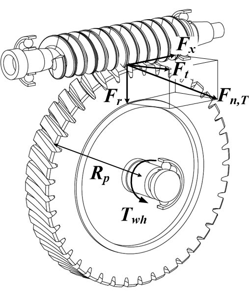
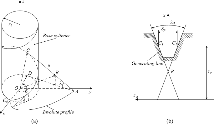
Figure 3Principal curves of worm. (a) Screw involute surface of ZI worm. (b) Geometry of straight-lined blade.
2.1 Power loss of worm gear
Power loss of worm gears is caused by friction on gear teeth, bearing loss, seal loss and loss due to oil churning (Townsend and Dudley, 1992). In the case of EPS systems, the worm gears are contained in a housing and use a grease type lubricant. Accordingly, seal and oil churning losses are negligible in this case. Klaus Michaelis has studied bearing and gear tooth friction losses (Michaelis et al., 2011). According to his study, gear tooth friction and bearing losses are divided into load dependent loss which occur even without power transmission, and load-dependent loss in the contact with power transmitting components. He has experimented different types of bearings at various conditions. Generally, bearing loss can be calculated by the following equation.
It is commonly accepted that gear tooth friction loss is the major source of efficiency dissipation in gears (Anderson et al., 1981; Velex and Cahouet, 2000). The efficiency of worm gears can be represented by the following equation.
2.2 Geometrical analysis
2.2.1 Normal load
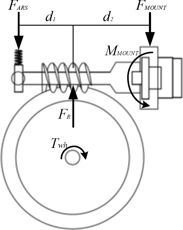
Figure 2 shows the force reactions of a worm gear when a steering torque is applied to the worm wheel. From the geometry, the normal load which acts on the tooth flanks can be calculated by the following equation.
In the case of a worm gear with a nylon worm wheel, surface contacts rather than point contacts occur between the worm and the worm wheel and therefore, its pressure and lead angles vary along the contact line of the surface. However, it is customary to assume point contacts and calculate force reactions under the assumption (Townsend and Dudley, 1992).
2.2.2 Contact point & normal pressure
Contact points between tooth surfaces can be obtained by analyzing the geometry of the worm shaft and the worm wheel.
Figure 3 shows a ZI worm. In the case of ZI worm gears, the surface of a worm is represented by the following equations (Litvin and Fuentes, 2004).
where , , , , ,
Figure 4 shows a worm wheel. The surface of a worm wheel is determined by a hob size and can be represented by the following equations.
In the case of worm gears in C-EPS systems, the worm wheel is machined by an oversized hob to reduce the sensitivity of worm gears to alignment errors (Simon, 2003). This worm wheel is theoretically in point contact with the worm thread, whereas a worm wheel processed by the hob whose generator surface is identical to the worm surface is in line contact with the worm thread (Zhao et al., 2012).
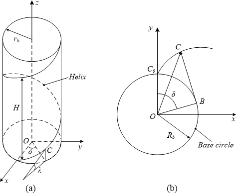
Figure 4Principal curves of worm wheel. (a) Geometry of worm wheel surface. (b) Involute curve of worm wheel.
In the case of worm gears with a nylon worm wheel, surface contacts over large areas occur between the worm and the worm wheel. Therefore, normal pressure at a contact point can be calculated by dividing normal load by contact area.
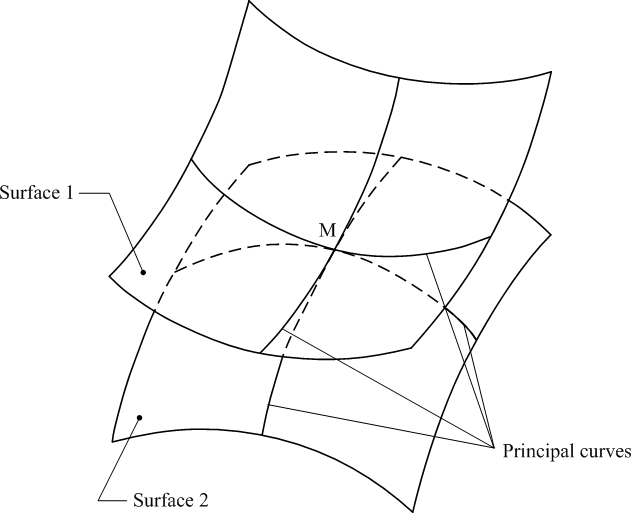
This study employs four principle curves in order to calculate the radii of curvature at a contact point – two from the worm shaft and the other two from the worm wheel as shown in Fig. 5. Then, Hertz's theory is used to calculate the contact area at the contact point. A worm shaft has two principal curves at a contact point. From the Eqs. (4)–(6), the explicit form of a function u1 is
In the case of ZI worm, a worm shaft is manufactured by a straight-line blade, which means the tooth line of the worm shaft is a straight line when it is viewed at the cross sectional surface which is parallel to the axis of the worm shaft. The other principal curve of the worm shaft at the contact point is
In the case of ZI worm, a worm wheel is manufactured by an oversized hob as mentioned. From the Eqs. (7)–(9), the explicit form of a function u2 is
and the point where the involute curve of the worm wheel crosses the pitch circle is
The radius of curvature in a worm gear can be calculated by the following equations.
where
where
where Rb=Rpcosα.
In this study, Hertz's theory is introduced to derive a contact area from the radii of curvature obtained from the equations above. When a worm gear is perfectly aligned, which means that the two pitch circles of the worm and the worm wheel are perfectly match each other, the mean position of the contact areas is on the pitch circle. However, if a misalignment occurs, their mean position is not on the pitch circle so their mean position should be calculated by considering the amount of the misalignment. Contact area at a contact point can be calculated by the following equations.
where
Consequently, normal contact pressure is
2.2.3 Misalignment
When a vehicle goes on a bumpy road, vibration and impact occur and are delivered to the steering system. In order to avoid tooth failure caused by these vibration and impact, the worm gear in the steering system needs flexibility and clearance in terms of design and assembly (Shin et al., 2014; Baxter and Dyer, 1988). In C-EPS systems, a worm wheel is located in the steering column and rotated by it. Therefore, an ARS is used to apply preload to one end of the worm shaft as shown in Fig. 1 (Rho, 2007; Shimizu et al., 2005). This ARS not only gives flexibility to the worm gear but also prevents the rattling sound and feel caused by vibration and impact.
As mentioned, in most worm gears, oversized hobs are introduced in machining worm wheels to reduce the sensitivity to misalignment and accordingly, the gear teeth of the worm wheels are in point contact with the worm thread. This point contact is assumed to spread over an elliptical area and be on the pitch circle (Simon, 2003). When a misalignment is considered, most studies have assumed the misalignment in the magnitude of 10 to 100 µm (Zhao et al., 2012; Sohn and Park, 2016). It is probably because most worm gears are supposed to work on static and stable bases. In the case of worm gears used in C-EPS systems, however, ARS with a large spring stiffness are used to prevent rattling and this causes larger misalignment than usually considered (Rho, 2007; Shimizu et al., 2005). When a spring stiffness and an initial misalignment value are known, misalignment according to output torque can be calculated. In Fig. 6, a force applied to the ARS by an output torque is
Hence, a misalignment by the output torque is
As the misalignment increases, the rotation angle of the worm shaft with respect to x axis increases and therefore, the misalignment of the worm shaft can be mathematically reflected by rotating the coordinate system of the worm shaft.
2.3 Tribological analysis
Friction coefficient
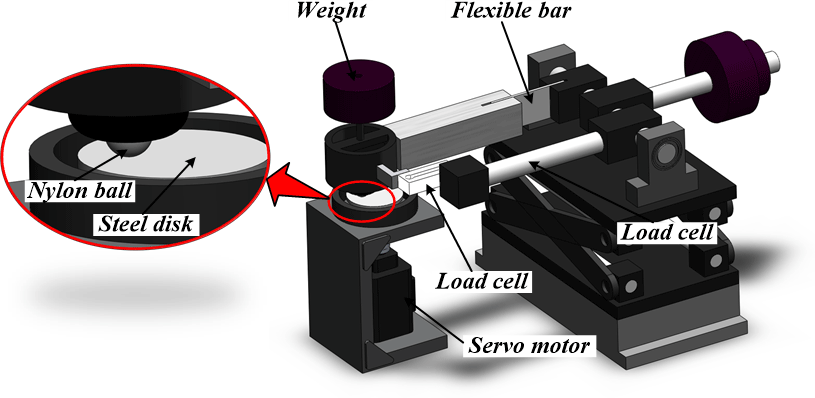
As shown in Eq. (2), friction coefficient is a key factor along with lead and normal pressure angles that determines transmission efficiency of worm gears. Considering lead and normal pressure angles are design parameters that are predetermined and do not change while running, friction coefficient is the only factor that affects the efficiency of worm gears. This study uses a tribometer to measure friction coefficients at various conditions. The tribometer is a pin-on-disk type as shown in Fig. 7. The pin and the disk are made up of the same materials as the worm wheel and the worm shaft, respectively. In the case of the worm gear prepared for the verification in this study, the pin is nylon6 and the disk is SUM43. The pin is located at the end of a flexible bar and the disk which has rotational motion by a motor is located underneath the pin. A load sensor located at the end of a rigid bar is attached to the screw cap which holds the pin inside. As the disk rotates with the pin on it, the load sensor can measure the friction force between the pin and the disk. The sliding velocity between the pin and the disk is controlled by the rotational speed of the pin and the distance from the center of the disk to the pin. In order to apply normal pressure to the pin, weights are placed on the pin and normal pressure can be controlled by the weights and the tip shape of the pin.
There are many researches that have studied contact mechanics and tribology. In steel-polymer contact, sliding velocity is not an important factor whereas normal pressure is still important for friction coefficient (Watanabe et al., 1968; Yamaguchi, 1990). Semaya Ahmed El Mowafi theoretically studied “Adhesion-shear theory” which dominates steel-polymer contact and experimentally verified the theory in his study (Mowafi et al., 1992). Friction coefficient decreases as normal load increases and it follows a power function of the form:
where, n is dependent on the type of motion between contact surfaces. From the experiments, n is −0.9 for sliding and −0.6 for rolling, which means friction coefficient is inversely proportional to normal load. In steel-polymer contact, on the other hand, sliding velocity hardly make difference on friction coefficient. Yakisaburo Yamaguchi experimentally showed in his study (Yamaguchi, 1990) and Makoto Watanabe derived empirical equations that represents the relationship between friction coefficient and sliding velocity (Watanabe et al., 1968). The equation is
where c,β are constants and β is 0.18 for nylon6, 0.13 for PTFE and 0.036 for HDPE.
2.4 Model Validation
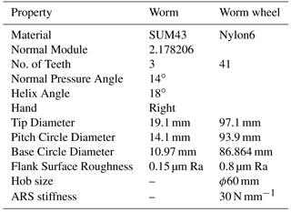
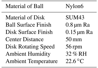
In this study, a worm gear set was prepared for the validation of the model. Its specifications including its ARS stiffness are indicated in Table 1. As shown, the worm is made up of SUM43 and the worm wheel is made up of Nylon6, which means that the worm gear has a polymer-steel contact. Geometrical analysis to find contact point, normal load and normal pressure was performed using the specifications in Table 1. For tribological analysis, a pin and a disk were prepared for the tribometer in Fig. 7. The pin and the disk are made up of the same materials as the worm wheel and the worm, respectively – Nylon6 for the worm wheel and SUM43 for the worm shaft. The experimental conditions are shown in Table 2. In order for accurate experiments, the pin and the disk were precisely manufactured in the same surface roughness as the worm wheel and the worm shaft. As mentioned, sliding velocity hardly affects friction coefficient so the disk rotating speed is set to 56 rpm in accordance with a worm wheel speed of 360∘ s−1.


2.4.1 Misalignment
Figure 8 shows the misalignment according to output torque of the worm gear. In the case of the worm gear tested in the measurement, an ARS with 30 N mm−1 of spring constant is used. The misalignment values indicate the height of the worm shaft tip from the aligned position. When the worm gear starts to run at 0 Nm output torque, misalignment is −1.10 mm, which means the worm shaft is pressed down by the ARS. As the output torque increases, the value increases and reaches 0 mm at 19.67 Nm, which means the worm shaft is perfectly aligned, and become positive values afterwards.
2.4.2 Friction efficient
Figure 9 shows friction coefficient according to normal pressure, which was experimented by the tribometer. Friction coefficient decreases as normal pressure increases and it reaches 0.029 at 130 MPa and then it starts to increase slightly afterwards.
2.4.3 Worm gear efficiency by model
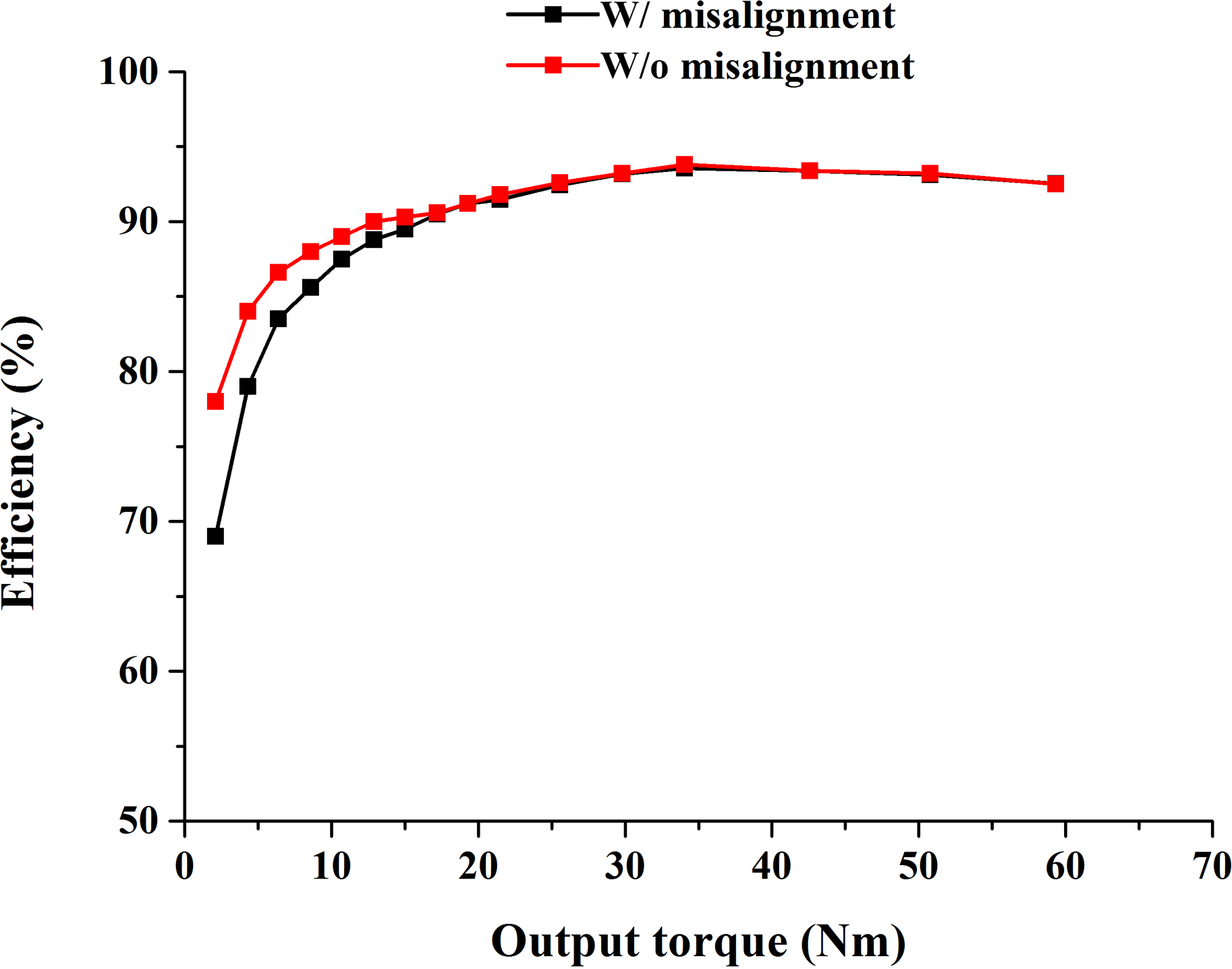
Figure 10 shows worm gear efficiency according to output torque, which is predicted by the model developed in this study. It shows the difference between the efficiencies with misalignment and without misalignment. As shown in Fig. 8, the misalignment is the largest at 0 Nm output torque and it starts to decrease as output torque increases. Hence, the predicted efficiencies also show the largest difference at 0 Nm output torque and start to decrease as output torque increases and the difference becomes zero when the misalignment is zero. Thereafter, two efficiencies do not show much difference.
2.5 Verification
2.5.1 Experimental setup
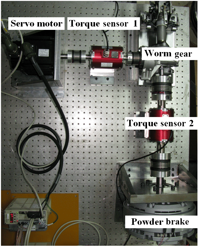
A worm gear efficiency measurement system was set up in this study in order to verify the efficiency model developed in this study. Figure 11 shows the efficiency measurement system. A worm gear set is located between a servo motor and a brake. The servo motor turns the worm gear at a certain speed and the brake applies resistant torque to the worm gear. There are two torque sensors used in this system – the one between the worm gear and the servo motor is to measure input torque, and the other between the worm gear and the brake is to measure output torque. As well as the measurement by two torque sensors, the control of the motor and brake are operated via a main controller. Experiments were performed in the range of 2 to 60 Nm of output torque and 360∘ s−1 of rotational speed. When a gear ratio is known, the efficiency of worm gears can be obtained by the following equation.
2.5.2 Experimental results
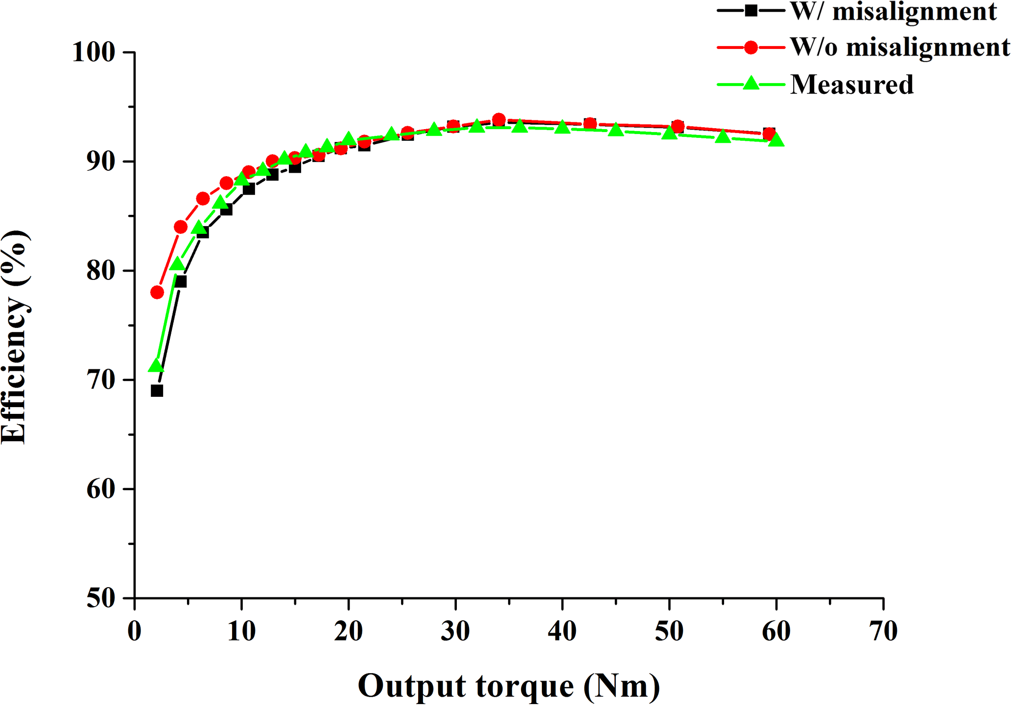
Figure 12 shows the verification results. The experimental results show the same efficiency trend as the results by the model. Efficiency increases as output torque increases and reaches its maximum value 93.10 % at 36 Nm and thereafter it slightly decreases.
A worm gear efficiency model considering misalignment was proposed in this study. A worm gear set is used in C-EPS systems and an ARS is also used in C-EPS systems in order to prevent the rattling that occurs between the gear teeth when the vehicle goes on a bumpy road. This ARS causes misalignment of the worm shaft and accordingly, generates undesirable friction.
Transmission efficiency of worm gears is represented by torque loss and the worm gear efficiency equation was derived in this study. It consists of lead and normal pressure angles, and friction coefficient. In order to obtain friction coefficients at various driving conditions, this study introduced geometrical and tribological analyses.
As a first step, normal load was calculated and the contact points between gear tooth surfaces were derived from the gear geometry. This study takes four principal curves into account at a contact point and Hertz's theory is employed to obtain the contact area at the contact point. Finally, the normal pressure at the contact point was found. A worm shaft misalignment by an ARS was applied to the coordinate system of the worm shaft in this stage.
A pin-on-disk type tribometer was set up in this study in order to measure friction coefficients at various conditions. Weight plates are placed on the pin to apply the normal pressure obtained from the geometrical analysis. Through the procedures, a worm gear efficiency model considering misalignment was developed.
In order to validate the model, a worm gear set was prepared and the efficiency of the worm gear was predicted by the model. The predicted efficiency with misalignment consideration is shown along with the efficiency without misalignment consideration. The efficiency with misalignment shows lower efficiency values than the efficiency without misalignment at low output torque conditions. As the final procedure of the study, the efficiency of the worm gear was measured by an efficiency measurement system and the results were compared with the predicted efficiency results. From the comparison, the predicted efficiency with misalignment consideration gives more accurate results than the predicted efficiency without misalignment consideration.
No data sets were used in this article.
A1 Notation
| Tb | torque loss of bearing (Nm) |
| fb | friction coefficient |
| Dp | 0.5(D1+D2) |
| D1 | bore diameter of bearing |
| D2 | Outside diameter of bearing |
| Wb | Load on bearing |
| η | Efficiency of worm gear |
| α | Normal pressure angle |
| μ | Friction coefficient |
| γ | Pinion lead angle |
| Fn,T | Normal load on tooth flank (N) |
| Twh | Worm wheel torque (N) |
| Rp | Pitch diameter of worm gear |
| rb | Radius of the base cylinder |
| u, θ | Surface parameters |
| rh | Radius of hob |
| rp | Radius of pitch circle of worm |
| sp | Length of two opposite tooth flanks on the pitch circle |
| k | ARS spring stiffness |
| MMOUNT | Moment at mount |
| Tin | Input torque |
| Tout | Output torque |
| m12 | Gear ratio |
A2 Abbreviations
| C-EPS | Column type Electric Power Steering |
| Anti-Rattle Spring | ARS |
| HPS | Hydraulic Power Steering |
| EHPS | Electro-Hydraulic Power Steering |
| EPS | Electric Power Steering |
| SBW | Steer-By-Wire |
| P-EPS | Pinion-type Electric Power Steering |
| R-EPS | Rack-type Electric Power Steering |
The author declares that he has no conflict of interest.
This work was supported by the Dong-A university research
fund.
Edited by: Chin-Hsing Kuo
Reviewed by: two anonymous referees
Anderson, N. E. and Loewenthal, S. H.: Effect of geometry and operating conditions on spur gear system power loss, ASME J. Mech. Des., 103, 151–159, 1981.
Baxter, J. and Dyer, G.: Bishop VARSATRONIC power steering system, SAE paper 880708, SAE international, Michigan, USA, 1988.
Bolourchi, F. and Chandy, A.: Torque-based on-center feel for electric power steering, USA, available at: https://patents.google.com/patent/EP2567880A3/es (last access: 28 May 2018), 2015.
Dang, J., Chen, H., Gao, B., Li, Q., Li, M., Watanabe, T., Hayama, R., Lou, L., and Nakano, S.: Optimal design of on-center steering force characteristic based on correlations between subjective and objective evaluations, SAE paper 2014-01-0137, SAE international, Michigan, USA, 2014.
Dong, L., Kandula, P., Gao, Z., and Wang, D.: On a robust control system design for an electric power assist steering system, Am. Control Conf., Baltimore, Maryland, 2010.
Kim, S. H. and Chu, C. N.: A new manual steering torque estimation model for steer-by-wire systems, Proc. Inst. Mech. Eng. S., 230, 993–1008, 2016.
Kim, S. H., Shin, M. C., Byun, J. W., O, K. H., and Chu, C. N.: Efficiency prediction of worm gear with plastic worm wheel, Int. J. Precis. Eng. Man., 13, 167–174, 2012.
Kim, S. H., Shin, M. C., and Chu, C. N.: Development of EHPS motor speed map using HILS system, IEEE T. Veh. Technol., 62, 1553–1566, 2013.
Li, Y., Shim, T., Wang, D., and Offerle, T.: Investigation of Factors Affecting Steering Feel of Column Assist Electric Power Steering, ASME 2016 Dynamic Systems and Control Conference, Minneapolis, Minnesota, 2016.
Litvin, F. L. and Fuentes, A.: Gear geometry and applied theory, Cambridge University Press, USA, 2004.
Michaelis, K., Höhn, B.-R., and Hinterstoißer, M.: Influence factors on gearbox power loss, Ind. Lubr. Tribol., 63, 46–55, 2011.
Mowafi, S. A. E., Khorshid, S. A. Y., and Mokhtar, M. O. A.: Prediction of friction coefficient for polymer-coated mechanical elements, Surf. Coat. Tech., 56, 39–46, 1992.
Rho, H. D.: Electric power steering system equipped with worm gear clearance compensator, USA, available at: https://patents.google.com/patent/US7527122B2/en (last access: 28 May 2018), 2007.
Shimizu, Y., Watanabe, K., Aoki, T., Terada, Y., and Toyofuku, R.: Worm gear mechanism and electric power steering apparatus equipped with the worm gear mechanism, USA, available at: https://patents.google.com/patent/US20040221669/fi (last access: 28 May 2018), 2005.
Shin, M. C., Kim, S. H., Cho, G. H., and Chu, C. N.: Development of a steering system model considering viscous friction and its verification, Proc. Inst. Mech. Eng. S., 228, 144–163, 2014.
Simon, V.: Load Distribution in Cylindrical Worm Gears, J. Mech. Des., 125, 356–364, 2003.
Sohn, J. H. and Park, N. G.: Study on the influence of gear hobbing and shaft misalignments on the geometric interference of cylindrical worm gear set, Proc. Inst. Mech. Eng. S., 231, 4646–4654, https://doi.org/10.1177/0954406216671543, 2016.
Townsend, D. P. and Dudley, D. W.: Dudley's gear handbook, McGraw-Hill, New York, USA, 1992.
Velex, P. and Cahouet, V.: Experimental and numerical investigations on the influence of tooth friction in spur and helical gear dynamics, ASME J. Mech. Des., 122, 515–522, 2000.
Watanabe, M., Karasawa, M., and Matsubara, K.: The frictional properties of nylon, Wear, 12, 185–191, 1968.
Yamaguchi, Y.: Tribology of Plastic Materials, Elsevier Science Publishing Company, New York, USA, 1990.
Zanten, A. T.: Bosch ESP systems: 5 Years of experience, SAE Automot. Dyna. and Stability Conf., Troy, MI, 2000.
Zaremba, A. T., Liubakka, M. K., and Stuntz, R. M.: Control and steering feel issues in the design of an electric power steering system, Proc. Am. Control Conf., Philadelphia, Pennsylvania, 1998.
Zhao, Y., Kong, J., Li, G., Wu, T., and Shi, S.: Computerized simulation of tooth contact and error sensitivity investigation for ease-off hourglass worm drives, Comput.-Aided Des., 44, 778–790, 2012.