the Creative Commons Attribution 4.0 License.
the Creative Commons Attribution 4.0 License.
Structural analysis of traditional Chinese hidden-keyhole padlocks
Kuo-Hung Hsiao
Hidden-keyhole padlocks use a plate or some other means to cover the keyhole and are a category of traditional Chinese padlocks. The topological structures of traditional hidden-keyhole padlocks have distinct arrangements in the operation. Therefore, they are reconfigurable mechanisms. This paper presents the structures of traditional Chinese hidden-keyhole padlocks, which were popular and had abundant types. The structural characteristics of hidden-keyhole padlocks are described first. Then, the representation for kinematic pairs appeared in operating steps is introduced. The variable chains of hidden-keyhole padlocks are presented by using the representation of kinematic pairs, from which all topology variabilities of hidden-keyhole padlocks in the operation are derived. Four main types of hidden-keyhole padlocks are provided as examples to illustrate the configuration transformations. This work presents a useful procedure to indicate and analyze the topology variabilities of hidden-keyhole padlocks.
- Article
(6982 KB) - Full-text XML
- Companion paper
- BibTeX
- EndNote
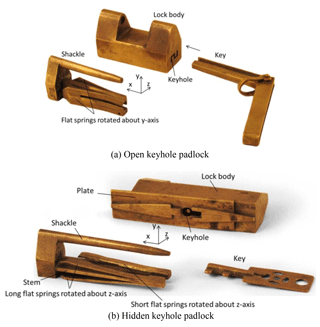
For thousands of years, the lock has been used widely in daily life. It is a mechanical device derived from people's pursuit of security. The flat-springs padlock is the representative design and was familiar around 200 AD in China. A flat-springs padlock is secured by a sliding shackle with one or more flexible flat springs, which, like fish hooks, easily move forward but resist moving backward. After entering the padlock, the flat springs spread out, and the shackle cannot be removed until the springs have been compressed again. Traditional flat-springs padlocks fall into two main groups (Yan, 2004): open-keyhole padlocks and hidden-keyhole padlocks, as shown in Fig. 1. There is a visible keyhole on the open-keyhole padlock that can be opened by a key inserting into the keyhole directly. It is the simplest design of a padlock. The hidden-keyhole padlock commonly makes use of a plate or some other means to hide the keyhole. Since the keyhole is covered and several obstacles have to be solved before opening lock, the hidden-keyhole padlock has better security than the open-keyhole padlock. Until now, plentiful hidden-keyhole padlocks with distinct features spread in the world.
China has a very long history, but there are very few articles discussing the development and applications of locks. Hommel (1937) introduced a few kinds of wooden locks frequently seen in ancient China and compared them with the wooden locks used in the countrysides of France, Germany, Italy, and more. Liu (1962) was the first researcher on Chinese traditional padlock based on modern mechanical point. In fact, the figure of Chinese flat-spring padlock in Needham's works (1965) came from Liu's. Needham (1965) delineated the brief history of the development of Chinese and Western locks and discussed their mutual influences. Tanavoli (1976) introduced the historic development of ancient Iranian locks, locksmith stories, lock types, and the lock manufacturing locations that they were important reference data for the studies of ancient Iranian locks. Millington (2010) described the early-stage combination locks, mechanism structures, and design principles of all the places around the world. He also taken care of the icons and meanings of the ancient locks according to the ancient combination locks handed over which had been important references for studying combination locks. Recently, a number of experts, scholars, and research institutes have invested in the related research of ancient Chinese locks. Yan systematically presented the developments and characteristics of Chinese locks (Yan, 2004), including subjects of historical developments, the language origin of the ancient locks, types of ancient locks, the materials of the locks, the structures of the lock bodies, keys, key holes, and unlocking of the ancients locks, etc. Based on the subject of the internal structures of ancient Chinese padlocks, Yan and Huang submitted one set of systematic design method for the keys, keyholes, and springs, and briefly described the development histories of Chinese and Western locks (Yan and Huang, 2000, 2004). They also compared the text meaning between Chinese and Western locks according to the encyclopedias and dictionaries. The National Science and Technology Museum held the “Locks and Keys 2000 Exhibition”, and published a catalogue introducing the locks of ancient China and early Europe. The locks are shown with beautiful photos together with brief texts describing their fundamental characteristics and functions (Li, 2000). Chen (2002) utilized his own stories about lock collections to write prose-style literary works, introducing the characteristics and developments of ancient Chinese locks, the experiences and key points of lock production, and the relationships between locks and cultures. Li (2007) categorized the locks into four types of knot locks, wooden locks, metal locks and electronic locks according to the lock materials, and respectively described the developments and applications of Chinese and Western locks together with their related historical stories and invention incidents. Ye and Ye (2012) organized the relevant records of locks in the Chinese literature in relation to ancient locks, and had introduced the locks' developments, craftsmanship and manufacturing, and cultural implications. Hsiao et al. (2012) analyzed the fundamental compositions of locks from the viewpoint of mechanical structure and discussed the design principles of ancient Egyptian wooden locks, ancient Chinese wooden locks, British Brahma locks, and pin-tumbler locks. Yu et al. (2013) explored the cultural implications and the evolution of locks, and the variations and applications of modern locks. Hsiao et al. (2016) classified the existing ancient Chinese wooden locks into five types and studied their component parts. Shi et al. (2017) studied the characteristics of traditional Chinese maze padlocks during operation and discussed the process of the key's insertion into the keyhole. Hsiao (2017) studied ancient Chinese open-keyhole puzzle locks and presented the variations in their topological structures. However, for the reconfigurable mechanisms developed by traditional Chinese hidden-keyhole padlocks, its topology analysis is still an open problem. A machine or mechanism design problem usually has an infinite number of solutions. In rough mathematical terms, the number of unknown parameters is usually orders of magnitude greater than available data of performance specifications, that is, equations. This uncertainty can be eliminated to a small extent by optimization methods and to the full extent by good technical judgment by the designer (Dimarogonas, 2001).
The aim of this work is to study the structural analyses of hidden-keyhole padlocks which were widely used before the 1950s in China. In what follows, Sect. 2 introduces the structural characteristics of traditional Chinese hidden-keyhole padlocks. Section 3 presents the representation of kinematic pairs of padlocks. Section 4 provides four examples of the structural analysis of hidden-keyhole padlocks. Section 5 is the conclusions of this work.
The necessary members of a hidden-keyhole padlock are shown in Fig. 1b. It is composed generally of the lock body, the shackle, the flat springs, the plate, and the key. The lock body has the keyhole that is covered by the plate. When the padlock is closed, it hangs from its shackle, which is held between the two upward extensions of the lock body. The flat springs are riveted to the opposite end of the stem. The splayed ends of the springs are trapped against a partition inside the lock body, preventing the release of the shackle. Since the shackle and stem are fixed together, they can be treated like one member. Open the padlock by finding the keyhole and inserting the key until the key-head compresses the flat springs and they are pushed through an opening in the partition. The shackle can now slide out the lock body to open the padlock. When the shackle is pushed back inside the lock body, the flat springs are slowly compressed as they pass through the opening in the partition. After the flat springs have passed completely through the opening they snap apart and are again trapped, securing the shackle in the padlock.
In general, in order to open a hidden-keyhole padlock, the user must first find a way to expose its keyhole. There are four main first steps to find out the keyhole, including sliding the plate, pushing the button, poking the hole, and rotating the decoration. It is an interesting and difficult process, because locksmiths used different manners to hide the keyhole.
According to the relative motions between the members of padlocks, nine types of kinematic pairs can be found in the operation, including prismatic pair (P), revolute pair (R), screw pair (H), cylindric pair (C), cam pair (A), planar pair (F), spring pair (SR), direct contact pair (DC), and fixed pair (X). Since the regular symbols of kinematic pairs (Suh and Radcliffe, 1978; Wilson and Sadler, 1993; Waldron and Kinzle, 1999; Norton, 2013) are not suitable to describe the characteristics of operation, a representation of such kinematic pairs that appear during operation is introduced as α±β, in which α and β respectively represent the type and the motion orientation of the kinematic pair. Subscripts + and − respectively represent the positive and negative axes with respect to the attached coordinate system. In general, the positive x axis is indicated as the direction of sliding out the shackle, the y axis is vertical to the horizontal plane, and the z axis is based on the right-hand rule (Hsiao, 2017).
Figure 1b shows a hidden-keyhole padlock with sliding bottom plate. In order to find the keyhole, the plate must be slid to left. The kinematic pair incident to the plate and the lock body is a prismatic pair, denoted as P+x, representing that the plate is translated along the positive x axis with respect to the lock body. After sliding the plate, the keyhole is appeared. The key is inserted into the keyhole. The kinematic pair incident to the key and the lock body can be denoted as P+z. Then, the key can be rotated in the keyhole and the corresponding kinematic pair is denoted as Rz.
The flat springs are adjacent to the stem with a kinematic pair that can be defined as a spring pair, denoted as SR. The relative motion between the spring and stem is planar and a rotation about an axis. Figure 1a shows only one set of the flat springs that can rotate about the y axis, denoted as SRy. Since the length of the flat springs is identical, they can be treated like one member. Figure 1b shows two sets of the springs that can rotate about the z axis with respect to the defined coordinate system, denoted as SRz. If the flat springs that are arranged symmetrically do not affect the operation, the motion orientation of the spring pair can be neglected. Otherwise, the flat springs are different in length. They should be treated like two members. And, the shackle must be slid from the lock body in two stages.
For a direct contact pair, denoted as DC, two members are connected by a direct contact due to an applied force and have no relative motion. For a fixed pair, denoted as X, two members are temporarily fastened and have no relative motion. Since the motion orientation of the direct contact pair and the fixed pair does not affect the operation, it can be neglected.
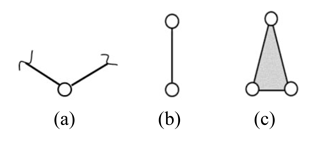
A mechanical device can be generalized as a generalized chain with only generalized links and kinematic pairs. The graphical representations of generalized kinematic pairs and links are shown in Fig. 2. Figure 2a shows a generalized kinematic pair with two incident links. Figure 2b and c shows a binary and a ternary generalized link, respectively. (Yan, 1998, 2007; Hsiao, 2013; Hsiao and Yan, 2014). In the same logic, a reconfigurable mechanism can be considered as a variable generalized chain, or variable chain, in short (Yan and Kuo, 2006; Hsiao, 2017). Hidden-keyhole padlocks encounter a certain changes in their topological structures in the operation. Therefore, they are reconfigurable mechanisms and can be illustrated with variable chains. Hidden-keyhole padlocks have four principle types: padlocks with a sliding plate, padlocks with a push button, padlocks with a poke hole, and padlocks with a rotating decoration. They are provided as examples to describe their operating steps and variable chains.
4.1 Padlocks with a sliding plate
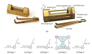
Hidden-keyhole padlocks with a sliding plate have three main sub-types: sliding end plate, sliding bottom plate, and sliding inside-end plate. A padlock with a sliding inside-end plate is presented in this work as shown in Fig. 3a. There is no additional plate, button, hole, decoration, or other hint on the lock body. It comprises six members: the lock body KLB (1), the shackle KS (2), the flat springs KSR (3), the inside-end plate KP1 (4), the end plate KP2 (5), and the key KK (6). In view of the topological variability, opening this padlock includes five operating steps.
4.1.1 Sliding the inside-end plate
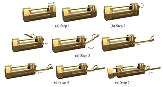
The first step is to slide the inside-end plates, located just below the shackle. The shackle and the flat springs are transient motionless. The inside-end plate and the end plate have no relative motion and can be treated like an assembly. It is slid to the negative x axis and is adjacent to the lock body with a prismatic pair P−x, Fig. 3b. Figure 4a shows the corresponding animation.
4.1.2 Rotating the end plate
After the end plate pops out, rotate it a quarter turn to expose the keyhole. The shackle, the inside-end plate, and the flat springs are transient motionless. The end plate is adjacent to the lock body with a revolute pair R−x, Fig. 3c. Figure 4b shows the corresponding animation.
4.1.3 Inserting the key
Since the keyhole is exposed, the key-head can be inserted, rotated, and pushed into the keyhole. The shackle, the inside-end plate, the end plate, and the flat springs are transient motionless. The key-head is placed horizontally over the keyhole and then adjacent to the lock body with a prismatic pair P+x, a revolute pair R−y, and a prismatic pair P+x, Fig. 3d. Figure 4c shows the corresponding animation.
4.1.4 Compressing the flat springs
When the key-head connects to the flat springs, the flat springs are compressed to pass through the opening in the partition. The inside-end plate and the end plate are transient motionless. The key is adjacent to the lock body and the flat springs with prismatic pair P+x. The flat springs are adjacent to the lock body and the shackle with a prismatic pair Pz and a spring pair SRy, respectively. The shackle is adjacent to the lock body with a fixed pair X, Fig. 3e. Figure 4d shows the corresponding animation.
4.1.5 Sliding out the shackle
After the ends of the flat springs has been parted from the partition of the lock body, the shackle can be moved by pushing the key and slid out of the lock body to open the padlock. The shackle, the flat springs, and the key can be treated like an assembly and is adjacent to the lock body with a prismatic pair P+x, Fig. 3f. Figure 4e shows the corresponding animation.
4.2 Padlocks with a push button
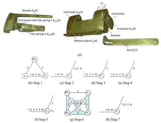
Hidden-keyhole padlocks with a push button are quite common, and there are many variations, such as a front push button, a bottom push button, and an end push button. A padlock with an end push button is presented in this work as shown in Fig. 5a. There is a button attached on each end plate. One is fixed and the other is movable. The padlock comprises seven members: the lock body KLB (1), the shackle KS (2), the end button with flat spring 1 KSR1 (3), flat springs 2 KSR2 (4), the end plate KP1 (5), the bottom plate KP2 (6), and the key KK (7). In view of the topological variability, opening this padlock includes seven operating steps.
4.2.1 Pushing the end button
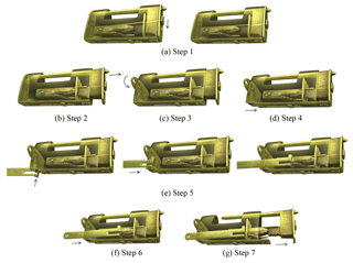
The first step is to push down on the movable end button to compress flat spring 1 to pass through the opening in the partition. Flat springs 2, the end plate, and the bottom plate are transient motionless. The end button with flat spring 1 is adjacent to the lock body and the shackle with a prismatic pair P−y and a spring pair SR−z, respectively. The shackle is adjacent to the lock body with a fixed pair X, Fig. 5b. Figure 6a shows the corresponding animation.
4.2.2 Sliding the shackle
After flat spring 1 passes the opening in the partition, the shackle can be slid to the positive x axis until it is trapped by flat springs 2. The end plate and the bottom plate are transient motionless. The shackle, the end button with flat spring 1, and flat springs 2 can be treated like an assembly and is adjacent to the lock body with a prismatic pair P+x, Fig. 5c. Figure 6b shows the corresponding animation.
4.2.3 Rotating the end plate
Since the shackle has been slid a little bit, the end plate can now be rotated and is adjacent to the lock body with a revolute pair R+x, Fig. 5d. Figure 6c shows the corresponding animation.
4.2.4 Sliding the bottom plate
Next, the bottom plate can be slid and is adjacent to the lock body with a prismatic pair P+x, Fig. 5e. Figure 6d shows the corresponding animation.
4.2.5 Inserting the key
After the bottom plate has been slid, the keyhole is fully exposed. The key-head is placed horizontally over the keyhole and then adjacent to the lock body with a prismatic pair P+y and a prismatic pair P+x, Fig. 5f. Figure 6e shows the corresponding animation.
4.2.6 Compressing the flat springs
In this step, the key is adjacent to the lock body, flat spring 1, and flat springs 2 with prismatic pairs P+x. The shackle is adjacent to the lock body and flat spring 1 with a fixed pair X and a spring pair SR−z, respectively. Flat springs 2 are adjacent to the lock body and the shackle with a prismatic pair Pyz and a spring pair SRyz, respectively, Fig. 5g. Figure 6f shows the corresponding animation.
4.2.7 Sliding out the shackle
The final step is to slide out the shackle. The shackle, flat spring 1, flat springs 2 and the key can be treated like an assembly and is adjacent to the lock body with a prismatic pair P+x, Fig. 5h. Figure 6g shows the corresponding animation.
4.3 Padlocks with a poke hole
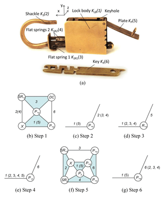
Some hidden-keyhole padlocks are smartly designed to use a small hole as a hint of the first step of opening the padlock. For opening this type of padlock, the point of the key or a pin must be poked into the small hole to press the flat spring or release a plate to find the keyhole. Figure 7a is selected as an example that comprises six members: the lock body KLB (1), the shackle KS (2), flat spring 1 KSR1 (3), flat springs 2 KSR2 (4), the plate KP (5), and the key KK (6). In view of the topological variability, opening this padlock includes six operating steps.
4.3.1 Poking the hole
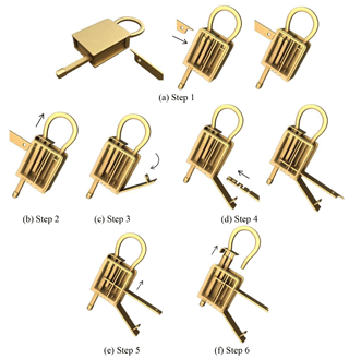
The keyhole is covered by the plate. However, the plate is fixed by the end of the curved-shackle. In order to release the plate, the shackle must be slid a little bit. There is a small hole on the lock body. Flat spring 1 is just behind the small hole and prevents the shackle from sliding. In the first step, the point of the key must be poked into the small hole to compress flat spring 1. The plate is temporarily immovable. The key is adjacent to the lock body and flat spring 1 with a prismatic pair P+y and a direct contact pair DC, respectively. The shackle and flat springs 2 can be treated like an assembly and is adjacent to the lock body with a fixed pair X. Flat spring 1 is adjacent to the lock body and the shackle with a prismatic pair P+y and a spring pair SR+z, respectively, Fig. 7b. Figure 8a shows the corresponding animation.
4.3.2 Sliding the shackle
After compressing flat spring 1, the shackle can be slid along the positive x axis until it is trapped by flat springs 2. The plate is temporarily immovable. The shackle, flat spring 1, and flat springs 2 can be treated like an assembly and is adjacent to the lock body with a prismatic pair P+x, Fig. 7c. Figure 8b shows the corresponding animation.
4.3.3 Rotating the plate
After the shackle has been slid a little bit, the plate has been released from the end of the curved-shackle. Therefore, the plate can be rotated and is adjacent to the lock body with a revolute pair R+z, Fig. 7d. Figure 8c shows the corresponding animation.
4.3.4 Inserting the key
After the plate has been rotated, the keyhole is exposed. The key is placed vertically over the keyhole and then adjacent to the lock body with a prismatic pair P−y, Fig. 7e. Figure 8d shows the corresponding animation.
4.3.5 Compressing flat springs 2
In this step, the key is adjacent to the lock body, flat spring 1, and flat springs 2 with prismatic pairs P+x. The shackle is adjacent to the lock body and flat spring 1 with a fixed pair X and a spring pair SR+z, respectively. Flat springs 2 are adjacent to the lock body and the shackle with a prismatic pair Pz and a spring pair SRy, respectively, Fig. 7f. Figure 8e shows the corresponding animation.
4.3.6 Sliding out the shackle
The final step is to slide out the shackle. The shackle, flat spring 1, flat springs 2 and the key can be treated like an assembly and is adjacent to the lock body with a prismatic pair P+x, Fig. 7g. Figure 8f shows the corresponding animation.
4.4 Padlocks with a rotating decoration
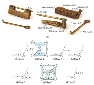
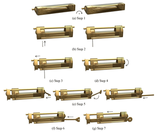
Decorations on the lock bodies of traditional Chinese padlocks show handicraft skills and great beauty. However, some decorations can provide a hint of the first step of opening a padlock. Figure 9a shows that there are two decorations attached to the bottom plate. One is fixed and the other is rotatable. The padlock comprises eight members: the lock body KLB (1), the shackle KS (2), flat spring 1 KSR1 (3), flat springs 2 KSR2 (4), the decoration KD (5), the end plate KP (6), key 1 KK1 (7), and key 2 KK2 (8). In view of the topological variability, opening this padlock includes seven operating steps.
4.4.1 Rotating the decoration
The first step is to rotate the decoration to find a small hole. The shackle, flat spring 1, flat springs 2, and the end plate are transient motionless. The decoration is adjacent to the lock body with a revolute pair R+y, Fig. 9b. Figure 10a shows the corresponding animation.
4.4.2 Poking the hole
Flat spring 1 is just behind the small hole. After finding the small hole, use key 1 to poke the small hole to compress flat spring 1. The decoration and the end plate are transient motionless. Key 1 is adjacent to the lock body and flat spring 1 with a prismatic pair P+y and a direct contact pair DC, respectively. The shackle and flat springs 2 can be treated like an assembly and is adjacent to the lock body with a fixed pair X. Flat spring 1 is adjacent to the lock body and the shackle with a prismatic pair P+y and a spring pair SR+z, respectively, Fig. 9c. Figure 10b shows the corresponding animation.
4.4.3 Sliding the shackle
After compressing flat spring 1, the shackle can be slid along the positive x axis until it is trapped by flat springs 2. The decoration and the end plate are transient motionless. The shackle, flat spring 1, and flat springs 2 can be treated like an assembly and is adjacent to the lock body with a prismatic pair P+x, Fig. 9d. Figure 10c shows the corresponding animation.
4.4.4 Rotating the end plate
After the shackle has been slid a little bit, the end plate can be rotated and is adjacent to the lock body with a revolute pair R−x, Fig. 9e. Figure 10d shows the corresponding animation.
4.4.5 Inserting the key
After the end plate has been rotated, the keyhole is exposed. Key 2 is placed horizontally over the keyhole and then adjacent to the lock body with a prismatic pair P+x, a revolute pair R−y, and a prismatic pair P+x, Fig. 9f. Figure 10e shows the corresponding animation.
4.4.6 Compressing the flat springs
In this step, key 2 is adjacent to the lock body, flat spring 1, and flat springs 2 with prismatic pairs P+x. The shackle is adjacent to the lock body and flat spring 1 with a fixed pair X and a spring pair SR+z, respectively. Flat springs 2 are adjacent to the lock body and the shackle with a prismatic pair Pz and a spring pair SRy, respectively, Fig. 9g. Figure 10f shows the corresponding animation.
4.4.7 Sliding out the shackle
The final step is to slide out the shackle. The shackle, flat spring 1, flat springs 2, and key 2 can be treated like an assembly and is adjacent to the lock body with a prismatic pair P+x, Fig. 9h. Figure 10g shows the corresponding animation.
Traditional Chinese hidden-keyhole padlocks are reconfigurable mechanisms and have plentiful types emerged in the world. They can be classified into four main types: padlocks with a sliding plate, padlocks with a push button, padlocks with a poke hole, and padlocks with a rotating decoration. The numbers of members of padlocks with a sliding plate are generally less than others and there are many variations. Padlocks with a push button come in many styles and are quite common. Poking the key into a hole to find out the keyhole is a clever and interesting way. Padlocks with a rotating decoration show ingenious puzzle features and great beauty. The structural characteristics of hidden-keyhole padlocks are studied first. According to the concluded characteristics, the configuration transformation of hidden-keyhole padlocks can be illustrated with the variable chains and the representation of kinematic pairs. By inspecting the variable chains during operation, it is more clear and straightforward to show the topological variation of hidden-keyhole padlocks. Four types are provided to demonstrate the process. It is a helpful tool to analyze the topological structures of hidden-keyhole padlocks systematically. Hidden-keyhole padlocks may induce the use of mathematics and advanced engineering design skills that were further investigated in the west and the Arabian world with similar padlocks, automata, clock mechanisms, and ingenious devices operating under similar principles. This implies a process of cross-fertilization in design and engineering of mechanisms that is scrutinized through the efforts of the IFToMM, Permanent Commission for History of Mechanism and Machine Science, the Needham Research Institute, the Ancient Chinese Machinery Cultural Foundation, the Classical Chinese Puzzle Foundation and other Organizations.
No data sets were used in this article.
The author declares that he has no conflict of interest.
The author is grateful to the Ministry of Science and Technology (Taipei,
Taiwan) under Grant MOST 106-2221-E-359-001- for the financial support of
this work. Support from the Ancient Chinese Machinery Cultural Foundation
(Tainan, Taiwan) and the Classical Chinese Puzzle Foundation (Berkeley, USA)
are greatly appreciated.
Edited by: Chin-Hsing Kuo
Reviewed by: Lie Sun and one anonymous referee
Chen, B.-R.: Ancient Chinese Locks, BaiHua Edition, Tianjin, China, 2002 (in Chinese).
Dimarogonas, A. D.: Machine Design: A CAD Approach, John Wiley and Sons Inc, New York, USA, 2001.
Hommel, R. P.: China at Work, John Day Company, New York, USA, 1937.
Hsiao, K.-H.: Structural Synthesis of Ancient Chinese Original Crossbow, T. Can. Soc. Mech. Eng., 37, 259–271, 2013.
Hsiao, K.-H.: On the Structural Analysis of Open-keyhole Puzzle Locks in ancient China, Mech. Mach. Theory, 118, 168–179, 2017.
Hsiao, K.-H. and Yan, H.-S.: Mechanisms in Ancient Chinese Books with Illustrations, Springer, Cham, Switzerland, 2014.
Hsiao, K.-H., Huang, H.-H., and Yan, H.-S.: Historical Development of Pin-tumbler Locks, Scientific Development, 474, 20–25, 2012 (in Chinese).
Hsiao, K.-H., An, H., Xiong, W.-Y., and Cheng, T.-F.: Ancient Chinese Wooden Locks, Technology Museum Review, 20, 41–54, 2016 (in Chinese).
Huang, H.-H.: Mechanism Design of Ancient Chinese Splitting-spring Padlocks, PhD Dissertation, National Cheng Kung University, Tainan, Taiwan, 2004 (in Chinese).
Li, J.-C.: Locks and Keys 2000 Exhibition Catalogue, National Science and Technology Museum, Kaohsiung, Taiwan, 2000.
Li, W.-S.: Illustration of Lock History, Shanghai Bookstore Press, Shanghai, China, 2007 (in Chinese).
Liu, X.-Z.: Historical Invention of Chinese Mechanical Engineering, Science Press, Beijing, China, 1962 (in Chinese).
Millington, J.: Early Combination Padlocks, Redcliffe Press, Bristol, UK, 2010.
Needham, J.: Science and Civilization in China, Vol. 4, Part II, Cambridge University Press, Cambridge, UK, 1965.
Norton, R. L.: Kinematics and Dynamics of Machinery, McGraw-Hill Companies, Singapore, 2013.
Shi, K., Zhang, Y., Lin, J.-L, and Hsiao, K.-H.: Ancient Chinese Maze Locks, T. Can. Soc. Mech. Eng., 41, 433–441, 2017.
Suh, C. H. and Radcliffe, C. W.: Kinematics and Mechanisms Design, John Wiley & Sons, New York, USA, 1978.
Tanavoli, P. and Wertime, J. T.: Locks from Iran – Pre-Islamic to Twentieth Century, Smithsonian Institution Traveling Exhibition Service, Washington, DC, USA, 1976.
Waldron, K. J. and Kinzel, G. L.: Kinematics, Dynamics and Design of Machinery, John Wiley & Sons, New York, USA, 1999.
Wilson, C. E. and Sadler, J. P.: Kinematics and Dynamics of Machinery, Harper Collins College Publishers, New York, USA, 1993.
Yan, H.-S.: Creative Design of Mechanical Devices, Springer, Singapore, 1998.
Yan, H.-S.: The Beauty of Ancient Chinese Locks, Ancient Chinese Machinery Cultural Foundation, Tainan, Taiwan, 2004.
Yan, H.-S.: Reconstruction Designs of Lost Ancient Chinese Machinery, Springer, Dordrecht, the Netherlands, 2007.
Yan, H.-S. and Huang, H.-H.: On the Spring Configurations of Ancient Chinese Locks, in: Proceedings of 2000 HMM International Symposium on History of Machines and Mechanisms, 11–13 May 2000, Casino, Italy, 2000.
Yan, H.-S. and Huang, H.-H.: Design consideration of ancient Chinese padlocks with spring mechanisms, Mech. Mach. Theory, 39, 797–810, 2004.
Yan, H.-S. and Kuo, C.-H.: Representations and Identifications of Structural and Motion State Characteristics of Mechanisms with Variable Topologies, T. Can. Soc. Mech. Eng., 30, 19–40, 2006.
Ye, D.-B. and Ye, L.-J.: Cultural History of Chinese Locks, Intellectual Property Publishing House, Beijing, China, 2012 (in Chinese).
Yu, A.-S., Hsiao, K.-H., and Zheng, J.-Q.: Exploration and Evolution of Locks, Science Monthly, 526, 774–779, 2013 (in Chinese).


