the Creative Commons Attribution 4.0 License.
the Creative Commons Attribution 4.0 License.
 | 02 Nov 2026
Design of a compact rotational compliant stage with self-compensation for rotation center offset
Bingyu Cai
Mahmud Iwan Solihin

Chaoran Chen
Xieben Wei
Xujin Lu
Zhe Lin
Hongyu Lin
Yawen Zhao
Compliant rotational stages are widely used for the fine angular positioning of optical components, where rotation center stability is critical to positioning accuracy. However, conventional designs often suffer from rotation center offset. A rotational compliant mechanism with self-compensation for rotation center offset is proposed based on a two-stage lever amplification system incorporating a non-vertical connecting beam and a double-ended fixed flexure hinge. The input force transmitted to the second-stage lever is decomposed into two orthogonal components. The y direction component drives the secondary lever to generate rotational motion, whereas the x direction component produces a negative x direction displacement through the double-ended fixed flexure hinge, thereby compensating for the rotation center offset. A kinematic analysis and a compliance model are established, based on which multi-objective dimensional optimization is performed to balance the rotational output and the center-offset indicator. The optimized design is subsequently evaluated using COMSOL finite element simulations. Under a prescribed relative input displacement of 28 µm, the mechanism produces an output rotation of 3.12 mrad, with a first natural frequency of 572 Hz and a maximum center offset of 0.42 µm. The stage has overall dimensions of 51 mm × 78 mm. These numerical results indicate that the proposed configuration can reduce rotation center offset and parasitic translational coupling under the adopted idealized simulation conditions.
- Article
(5769 KB) - Full-text XML
- BibTeX
- EndNote


With the rapid advancement of micro-/nano-fabrication technology, high-precision positioning has found increasingly extensive applications in fields such as micro-/nano-assembly, optical alignment, and biological cell manipulation (Qin et al., 2021; Wei and Xu, 2019; Gong et al., 2022; Barber et al., 2011). Among various solutions for achieving precision motion, compliant stages driven by piezoelectric ceramics have attracted significant attention due to their compact structure, smooth motion, absence of backlash, and capability for nanometer-level displacement resolution (Chen et al., 2020; Habibullah, 2020). Compared to traditional rotation mechanisms relying on bearing transmission, compliant mechanisms transmit motion through the elastic deformation of materials, fundamentally avoiding non-linear factors such as friction, wear, and clearance, thereby significantly enhancing the positioning accuracy and dynamic response performance of the system (Baek et al., 2020; Huang et al., 2024).
Currently, rotational motion stages based on compliant mechanisms can be primarily categorized into two types. The first is the multi-degree-of-freedom (multi-DOF) micro-positioning stage, which integrates rotational motion into translational motion, with the most typical example being the three-DOF XYθ stage (Wang and Zhang, 2016). It can achieve both in-plane translational motion and rotational motion about an axis perpendicular to the plane. For instance, Kim and Gweon (2012) employed composite mechanisms such as bridge-type amplification, double compound guidance, and circular hinges to propose a novel XYθ piezoelectric-driven stage featuring a serial structure and a hybrid compliant mechanism. Yu et al. (2019) proposed a large-stroke 3PPR planar compliant parallel mechanism based on compliant four-bar joints and double-leaf spring hinges. Although such stages can achieve the desired rotational motion, they often suffer from undesired coupling effects between translational and rotational motions, leading to drift of the rotation center (Cai et al., 2025).
The second type is the single-degree-of-freedom(1-DOF) rotational micro-positioning stage, which can reduce the coupling effects of translational motion and achieve superior system performance. Compared to the traditional planar XYθ micro-positioning stages, the current research on such 1-DOF rotational micro-positioning stages based on compliant mechanisms remains relatively limited. Zhu et al. (2018) developed a compact single-layer stage with a rotational range of 1.58 mrad. Although its absolute center offset was relatively small, its rotational range and normalized center-offset performance leave room for further improvement. Mu et al. (2025) presents a parallel compliant rotational stage driven by two voice coil motors (VCM) in a symmetrical layout, which achieves a large rotational range of over 41.6 mrad. However, due to the characteristics of VCM, several issues arise. Firstly, they significantly increase the volume and weight of the micro-positioning stage, which is detrimental to achieving a compact and lightweight design. Secondly, they lead to a low natural frequency and poor dynamic performance of the positioning stage (Yang et al., 2021). Thirdly, the use of two VCM introduces redundant actuation and electromagnetic interference. Both the rotational compliant mechanisms proposed by Clark et al. (2016) and Guo et al. (2023) adopt a two-layer structure. This approach trades off larger volume, more complex structure, lower stiffness, and inferior dynamic performance in exchange for a larger range of motion. These designs prioritize a larger rotational range, but their multi-layer configurations or VCM-based actuation may lead to increased structural size and lower natural frequencies. The summary of related research is presented in Table 1.
The proposed stage adopts a single-layer and single-PZT configuration with a footprint of only 51 × 78 mm2, which is the smallest among the compared designs. Compared with the double-layer design of Guo et al. (2023), its footprint is reduced by approximately 50.3 %, while its first natural frequency is increased from 192.45 to 572 Hz. In addition, the absolute center offset is reduced from 1.29 to 0.42 µm, corresponding to a reduction of approximately 67.4 %. Although the output-angle amplification ratio is lower, the proposed stage maintains a sufficiently large rotational range of 3.12 mrad while preserving substantially higher structural stiffness and dynamic frequency.
Compared with the more structurally similar single-layer stage reported by Zhu et al. (2018), the proposed stage provides a 97.5 % larger output angle, a 33.0 % higher first natural frequency, an 18.8 % smaller footprint, and a 28.9 % lower center shift per unit rotation angle. Therefore, the principal advantage of the proposed design lies in its balanced combination of compact single-layer construction, high natural frequency, sufficient rotational range, and low rotation center offset.
Table 1Comparison of rotational compliant positioning stages. The amplification ratio is defined as the output angle per unit input displacement (mrad µm−1); center shift per angle normalizes the center offset by the output angle (µm mrad−1); angle per area normalizes the rotational range by the footprint (mrad mm−2).

To simultaneously meet application requirements for high stiffness, large rotational range, compact footprint, and minimal center offset, this paper presents a novel design for a rotational compliant mechanism with self-compensating capability for rotation center offset. The proposed design utilizes a two-stage lever amplification system to achieve rotational motion, while incorporating specifically designed flexure hinges and an input lever in the second stage to actively compensate for the rotation center offset. Its self-contained working principle and actuation method enable seamless integration with other systems. Compared to our earlier work (Cai et al., 2024), which established a two-stage lever amplification mechanism for rotational motion but suffered from center offset issues, the present design achieves a significantly improved rotational accuracy. In this paper, Sect. 2 introduces the novel design concept of the rotational compliant mechanism. Subsequently, Sect. 3 establishes the analytical model for the rotational compliant mechanism. Based on the compliance model from Sect. 3, Sect. 4 conducts a multi-objective optimization of the key geometric parameters. Section 5 employs the finite element method for simulation analysis and evaluation of the structure. Finally, Sect. 6 presents the conclusions.
2.1 Intended application scenario and design requirements
The proposed compliant rotational stage is intended for the fine angular positioning of small optical components, such as mirrors or lenses, in compact laser alignment, microscopy, and optical metrology systems (Jeong et al., 2007; Lee et al., 2019; Qu et al., 2016; Ye and Li, 2023). In these applications, a small rotational motion must be generated about an approximately stationary center. Rotation center drift and parasitic translational motion may cause optical-axis deviation or positioning errors, particularly when the rotational stage is integrated into a compact precision instrument.
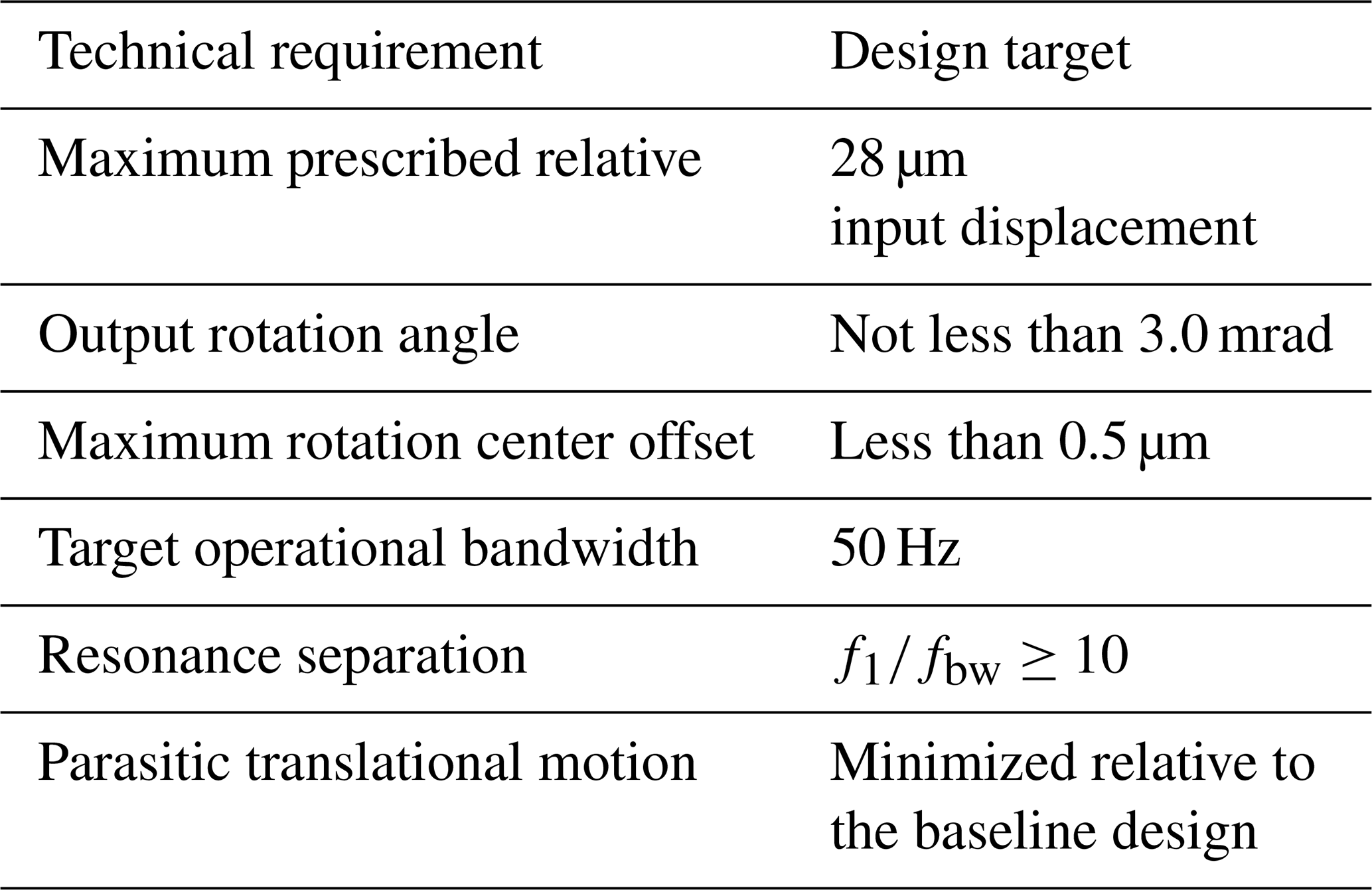
The main technical challenges are therefore to obtain sufficient angular output from the limited stroke of a PZT actuator, suppress rotation center offset and parasitic translations, and maintain adequate separation between the operating frequency range and the structural resonances. Based on the intended precision-positioning application and relevant studies, the application-oriented design targets adopted in this study are listed in Table 2. These requirements are study-specific design targets for the intended application rather than universal performance standards.
2.2 Self-compensating compliant mechanism for rotation center offset
Since the stroke of piezoelectric actuators is typically only several tens of micrometers, displacement amplification mechanisms are commonly employed to achieve a larger range of motion. Therefore, this paper aims to present a compact lever amplification mechanism that enhances the motion range and achieves higher rotational accuracy, thereby meeting the requirements of a wider variety of working conditions. The initial structural design is shown in Fig. 1. The input of the lever amplification mechanism is placed in the middle of the beam. The two-stage amplification mechanism is connected by an inter-stage connecting beam.
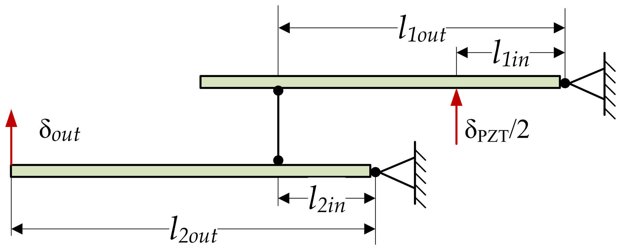
Figure 1Initial structure design (Cai et al., 2024).
Although this initial design fulfills the fundamental requirement for rotational motion, it exhibits certain limitations. As illustrated in Fig. 2, a center offset exists between the actual rotation center at the output point of the secondary lever and the desired center of rotation. Consequently, a certain degree of linear coupled displacement will occur at the output point. This undesirable condition will result in internal interactive forces between the lever mechanism and the end-effector stage. Once the rotational displacement becomes sufficiently large, this coupling effect cannot be neglected, as it introduces undesired out-of-plane deformations.

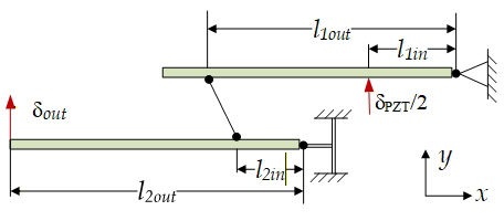
Based on the initial design, improvements have been implemented. As shown in Fig. 3, a double-ended fixed flexure hinge is first incorporated into the joint of the secondary lever amplification stage. Subsequently, the connecting beam between the two lever amplification stages is designed with a non-vertical configuration. Under the action of the non-vertical force, the input force is decomposed into two component forces: one vertical upward (positive y direction) and the other horizontal leftward (negative x direction). The component force in the positive y direction drives the secondary lever to generate rotational motion, while the component force in the negative x direction induces a displacement in the negative x direction through the double-ended fixed flexure hinge. This displacement thereby compensates for the rotation center offset. Accordingly, it is essential to derive the compliance model of the compliant mechanism and then perform multi-objective optimization of the structural parameters to achieve near-pure rotational output and a larger motion range.
2.3 Design of the rotational compliant stage
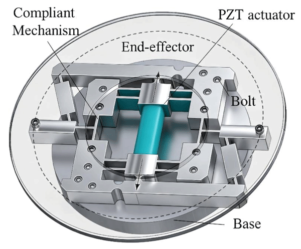
Based on the self-compensating compliant mechanism for rotation center offset proposed above, a rotational compliant micro-stage has been designed, as illustrated in Fig. 4.
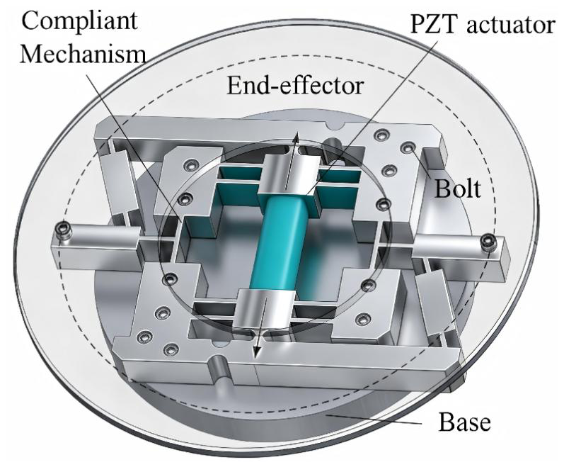
The mechanism employs a single actuation input, requiring only one micro-displacement actuator to achieve rotational displacement output, thereby avoiding issues of actuation redundancy. This approach not only reduces costs but also simplifies the control system. Furthermore, to transform the imperfect actuation source under practical conditions into an ideal linear input, the input does not adopt direct force application. Instead, a leaf-spring-based flexural input guidance mechanism is connected to the PZT, replacing mechanical contact with elastic deformation. This mechanism acts as a physical motion filter that suppresses parasitic motions through directional stiffness configuration and error isolation.
The compliant mechanism exhibits a centrosymmetric configuration and comprises two parallel branches. Each branch consists of a two-stage lever displacement amplification mechanism and a guidance mechanism. The parallel design with integrated guidance mechanisms allows the micro-displacement PZT actuator to be nested centrally, leading to more balanced stress distribution on both sides. Finally, the output point at the terminal end of the secondary lever beam is rigidly connected to the end effector, transmitting the rotational displacement from the compliant mechanism to the work stage. Using the pseudo-rigid-body model, the two-stage lever amplification structures can be simplified as in Fig. 5. Furthermore, should a larger range of motion be required, the entire design can be extended to three or even more amplification stages by connecting additional lever mechanisms, thereby accommodating specific application demands.
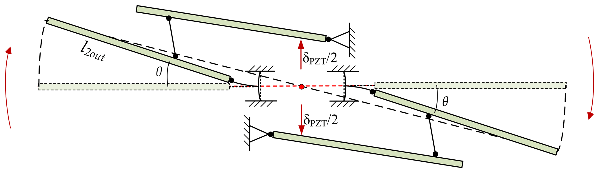
The designed compliant mechanism consists of a centrosymmetric two-stage lever amplification system. Therefore, to establish the output compliance of the entire mechanism, it is sufficient to calculate the compliance of a single-side two-stage lever amplification mechanism. As shown in Fig. 6, a global coordinate system O-xy is established at the stage's rotation center, and a local coordinate system is set up on the inter-stage connecting beam, with all key points annotated.
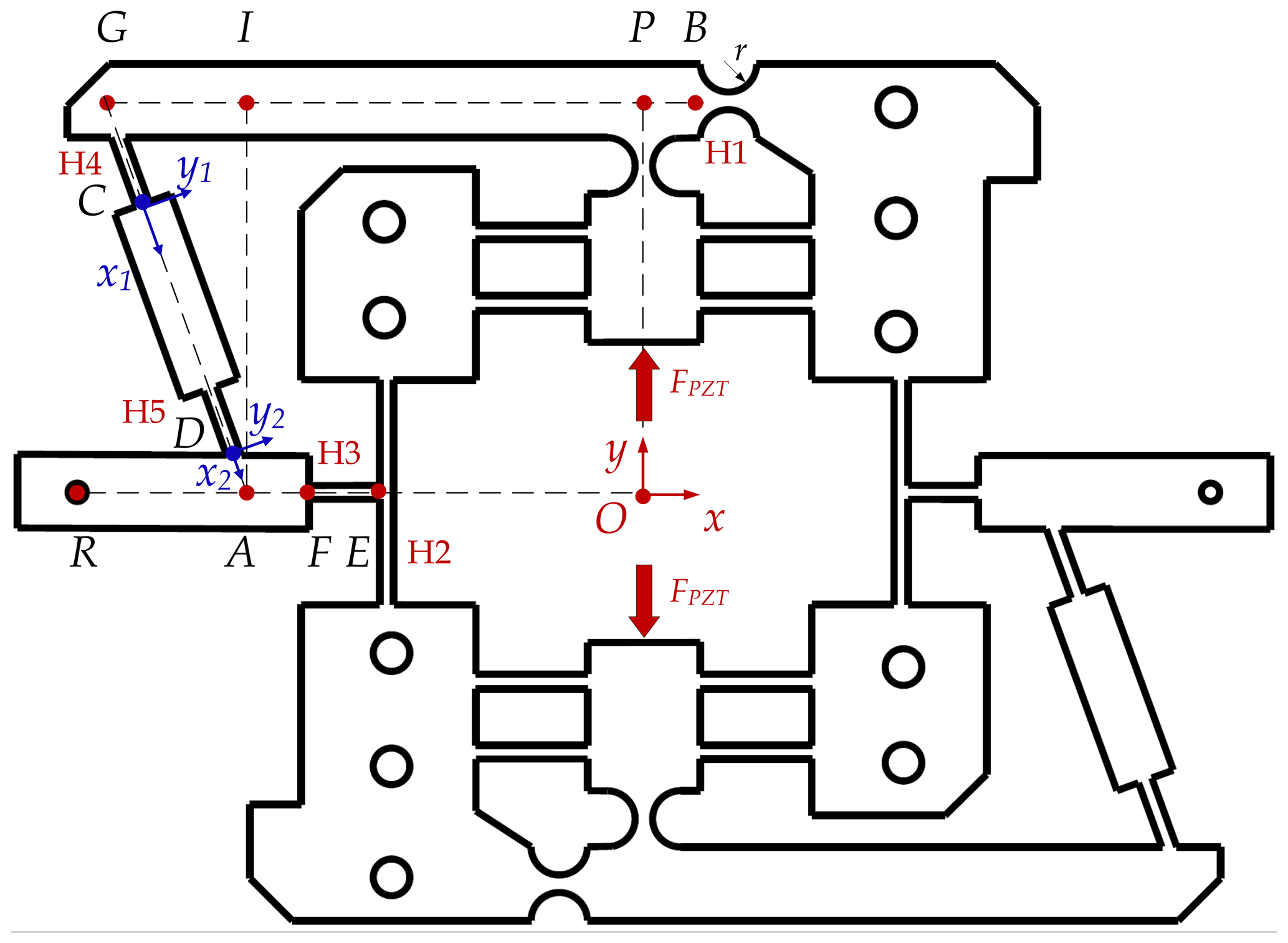
Figure 6Schematic of the rotational compliant stage showing the coordinate system and labeled points.
3.1 Modeling assumptions and sign conventions
To clarify the compliance derivation, coordinate transformations, and matrix assembly, the assumptions, coordinate systems, and sign conventions adopted in the analytical model are summarized as follows.
-
The mechanism is modeled as a planar system in the global x-y plane. Only the two in-plane translational degrees of freedom and the rotation about the z axis are considered. Out-of-plane translations, out-of-plane rotations, and torsional deformation are neglected.
-
Small deformation and small rotation are assumed. First-order linear kinematics are used, while higher-order geometric terms and geometric stiffening or softening effects are neglected.
-
Except for flexure hinges H1–H5, the connecting links, lever segments, and end effector are treated as ideally rigid bodies. Structural deformation is concentrated in the flexure regions, and the local elastic deformation of nominally rigid members is not represented separately in the lumped-compliance model.
-
The material is assumed to be homogeneous, isotropic, and linearly elastic. The flexure compliances are calculated from the closed-form expressions given in the article. Material nonlinearity and residual stress are not considered.
-
Assembly errors, contact and friction, PZT hysteresis and creep, and thermal effects are not included in the analytical model.
To avoid ambiguity in the coordinate transformations and compliance-matrix operations, the principal variables and sign conventions used in the analytical model are summarized in Table 3. Unless otherwise specified, all generalized displacement and load vectors are expressed in the global coordinate system O-xy.
Table 3Definitions of the principal variables and sign conventions used in the analytical model.

3.2 Compliance modeling of the single-side two-stage lever amplification mechanism
The compliance model of the mechanism comprises three parts: the first lever amplification mechanism, the inter-stage connecting beam, and the second lever amplification mechanism. The employed flexure hinges include both leaf-type and circular notch, labeled H1 to H5, respectively. The following analysis divides the mechanism into these three segments and utilizes the compliance matrix method to derive the overall compliance model (Yong, 2007; Yong and Lu, 2009).
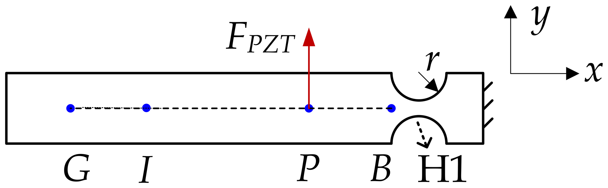
As shown in Fig. 7, the first lever amplification mechanism consists of a lever beam (lGB), a circular notch flexure hinge (H1), and a fixed support. Based on the compliance matrix theory, the displacement at the point B can be calculated as:
where
Then, the displacement of point B can be calculated as
According to the geometry of the lever mechanism, the displacement of point A can be determined by transferring the displacement of point B, which is
According to the compliance matrix theory, the displacement at point A under the action of the flexure hinge H1 is given by
Therefore, the compliance at point A of the first-stage lever amplification mechanism can be obtained as
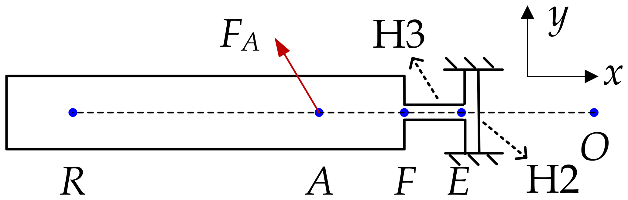
As shown in Fig. 8, the second lever amplification mechanism consists of a lever beam (lRF), two leaf-type flexure hinges (H2, H3), and a fixed support. The flexure hinge H2 can be modeled as a fixed-fixed leaf spring, primarily providing compensation for the rotation center offset. The flexure hinge H3 can be treated as a cantilever beam, mainly enabling rotational motion. Since the compliance of the two flexure hinges at point A is connected in series, the compliance of each flexure hinge at point A is determined separately.
Based on the compliance matrix theory, the displacement at the point E can be calculated as
where
Then, the displacement of point E can be calculated as
According to the geometry of the lever mechanism, the displacement of point A can be determined by transferring the displacement of point E, which is
According to the compliance matrix theory, the displacement at point A induced by flexure hinge H2 can be expressed as
Therefore, the compliance at point A under the action of flexure hinge H2 can be calculated as
Similarly, the compliance at point A under the action of flexure hinge H3 can be calculated as
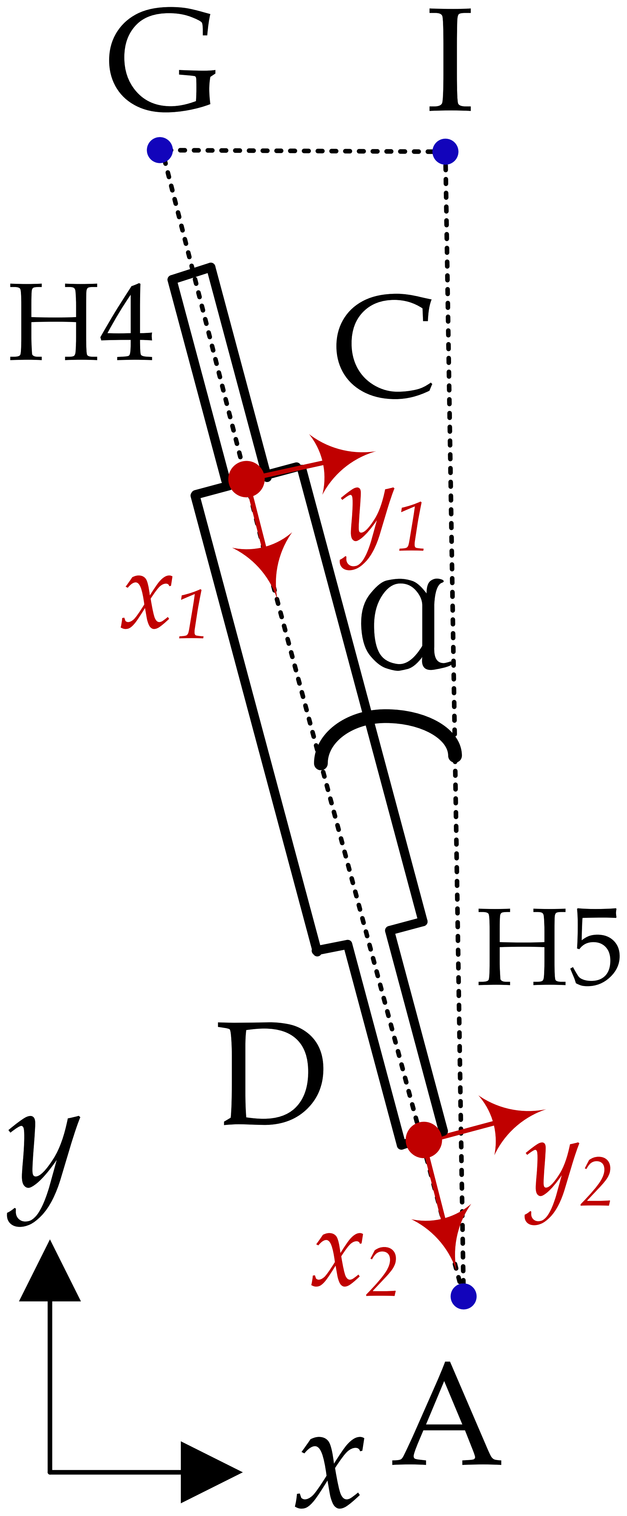
As shown in Fig. 9, the inter-stage connecting beam consists of two leaf-type flexure hinges (H4, H5) and a connecting beam. First, local coordinate systems are established at points C and D. The force at point A is then transformed from the global coordinate system to these local coordinate systems and subsequently transferred to point C to obtain the force at point C expressed in the local coordinate system.
where
Based on the compliance matrix theory, the displacement at the point C can be calculated as
Then, the displacement of point A in the local coordinate system is obtained from the displacement of point D, and finally transformed into the displacement in the global coordinate system through coordinate transformation.
Based on the compliance matrix theory,
Therefore, the compliance at point A under the action of flexure hinge H4 can be determined as
Similarly, the compliance at point A under the action of flexure hinge H5 can be determined as
As shown in Fig. 6, to determine the compliance at point A, flexure hinges H1, H4, and H5 are connected in series. Therefore, the total compliance at point A for the first lever amplification mechanism and the inter-stage connecting beam can be expressed as
Similarly, since the compliance of flexure hinges H2 and H3 is connected in series, the total compliance of the second lever amplification mechanism at point A can be expressed as
Since CA1 and CA2 are connected in parallel at point A, the total compliance of the two-stage lever mechanism at point A can be expressed as
Based on the compliance matrix theory, the displacement at point A is
The displacement at point A is then transferred to point R, yielding the displacement at point R as
The force from the piezoelectric ceramic micro-actuator is transferred to point A, yielding the force at point A as
Finally, by combining Eqs. (27), (28), and (29), the displacement at point R can be obtained as
3.3 Motion-stage constraint and input–rotation relationship
For the ith branch, let the equivalent compliance matrix and the generalized actuation-force transmission vector at point Ai be defined in the same global coordinate system. The force transmission vector includes both the actuation direction and the orientation of the corresponding branch. The generalized displacement of the rigid end effector at the nominal rotation center O is defined as
where the first two components are the translational displacements of the end effector and θ is its output rotation angle.
Because Ai and Ri are located on the same nominally rigid member, their generalized displacements are related through the rigid-body transformation:
where
The equivalent compliance and stiffness matrices of the ith branch at point Ri are consequently obtained as
Let xi and yi denote the initial coordinates of point Ri relative to O. Since Ri is rigidly connected to the end effector, its displacement must satisfy the rigid-body compatibility condition:
with
Under the actuation force Fi, the free displacement of point Ri predicted by the original A-point compliance model is
Let pi denote the generalized reaction exerted by the rigid end effector on the ith branch at Ri. The actual displacement of Ri is then
Combining the branch compliance relation with the rigid-body compatibility condition gives
For an unloaded end effector, the reactions at R1 and R2 must satisfy the overall force and moment equilibrium condition:
Substitution of the reaction forces yields the stage-constrained equilibrium equation:
where
Therefore, the generalized motion of the rigid end effector and its rotation angle are given by
where
For the centrosymmetric mechanism, the two branches are subjected to the same actuation-force magnitude F. The vectors b1 and b2 are selected according to the actual opposite actuation directions of the two branches. Define
The force-driven relationship can then be written as
The displacement constraint imposed by the PZT actuator is further introduced. According to the principle of virtual work, the input displacement of the ith branch, measured along its own actuation direction, is
Let the total PZT displacement denote the relative displacement between the two ends of the actuator. Owing to the centrosymmetric configuration and the identical input stiffnesses of the two branches, the two branch input displacements have equal magnitudes and jointly form the total actuator stroke:
Substituting the force-driven relation above, the input compliance of either branch under the end-effector constraint is
For the centrosymmetric branches, the constrained input compliances of the two branches are identical. The actuation force corresponding to the prescribed total PZT displacement is therefore
Finally, substituting the PZT displacement constraint into the stage-constrained force-driven model gives the direct relationship between the total PZT displacement and the output rotation angle:
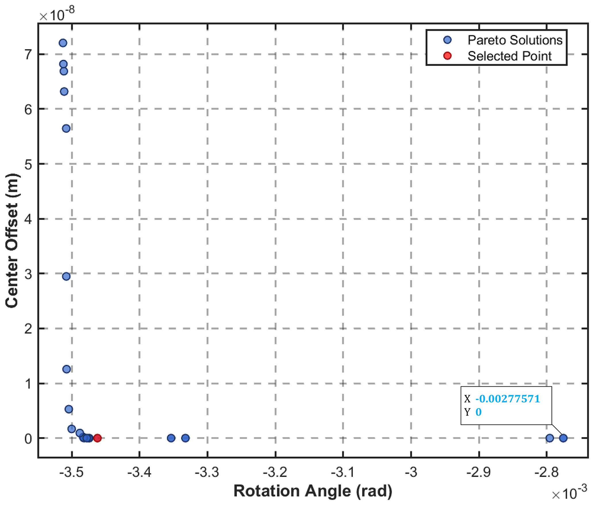
Table 4Design parameter ranges considered for optimization. L (length of the fixed-fixed hinge), b (width of the flexure hinge), t (minimum thickness of the hinge at the center), 2a (length of the leaf-type hinge), l (distance between points), α (included angle), r (radius of the circular notch flexure hinge). Considering practical machining precision, the optimization results were rounded to one decimal place.
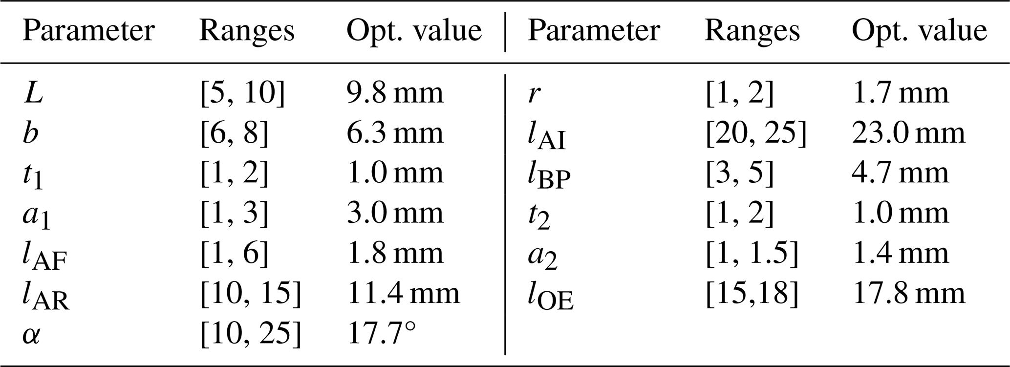
To minimize internal motion coupling within the compliant mechanism and achieve near-pure rotational displacement output (although the centrosymmetric architecture inherently reduces motion coupling to some extent), it is necessary to ensure minimal variation in the distance between point R and the rotation center O before and after rotation. The Pareto multi-objective optimization method, originally introduced by Italian economist Vilfredo Pareto, addresses optimization problems involving conflicting objectives. Thus, this approach is well-suited for optimizing the performance parameters of compliant mechanisms (Li et al., 2021).
As shown in Fig. 6, the distances between the two points and the change in the two distances can be determined as follows:
where is the original distance without any input, is the distance with input, and δ is the change in two distances.
The parameters of the dimensions were optimized using a multi-objective approach, with the dual objectives of minimizing coupling and maximizing the rotational motion range.
The optimization was implemented in MATLAB using the gamultiobj solver. Since gamultiobj minimizes all objective functions, the two objectives were formulated as follows:
The population size was set to 300, the maximum number of generations was set to 1000, and the Pareto fraction was set to 0.1. The maximum number of stall generations and the function tolerance were set to 500 and 1 × 10 −100, respectively. The evolution of the Pareto front was monitored using the gaplotpareto function. The remaining genetic operators, including population initialization, selection, crossover, and mutation, retained their MATLAB default settings. The optimization was terminated when either the maximum number of generations was reached or the change in the Pareto front spread satisfied the prescribed stall-generation and function-tolerance criteria.
After defining the optimization parameters and their ranges, Pareto multi-objective optimization was employed to obtain the Pareto frontier shown in Fig. 10. The resulting non-dominated solutions describe the trade-off between rotational output and rotation center offset. The final geometric parameters were selected from the Pareto set by jointly considering a large output rotation, a small value of δ, and satisfaction of all geometric constraints. The selected parameters are summarized in Table 4.

5.1 Finite element model and numerical settings
The finite element analysis was performed using COMSOL Multiphysics 6.0 with the Solid Mechanics interface. A three-dimensional model of the compliant stage was established using AL7075-T651, which was assumed to be homogeneous, isotropic, and linearly elastic. The model was discretized using free tetrahedral mesh elements with quadratic displacement shape functions, and the flexure-hinge regions were locally refined.
The mounting surfaces of the base were fully constrained, while the bolts were not explicitly modeled and replaced by fixed constraints at the mounting holes. The PZT actuator was represented by prescribed displacements of and at the two input interfaces, respectively, so that each centrosymmetric branch received one-half of the total actuator displacement. In the displacement-controlled finite element analysis, the prescribed displacement of 28 µm represents the actual relative displacement delivered between the two actuator–stage interfaces, rather than the unloaded free stroke of the PZT actuator. The end effector was modeled as a rigid domain. A stationary study was performed using the default solver settings, with geometric nonlinearity enabled.
5.2 Mesh convergence study
A mesh-convergence analysis was conducted to evaluate the influence of mesh density on the finite element results. Since the deformation of the proposed mechanism is mainly concentrated in the circular-notch and leaf-type flexure hinges, the flexure regions were locally refined to accurately capture their deformation characteristics. Four mesh levels available in COMSOL, namely Normal, Fine, Finer, and Extra-fine meshes, were examined. The corresponding finite element models contained 14 685, 37 664, 141 989, and 325 031 elements, respectively.
The output rotation angle under the maximum prescribed input displacement of 28 µm was selected as the convergence indicator. The output rotation angles obtained using the normal, fine, finer, and extra-fine meshes were 3.061, 3.098, 3.116, and 3.120 mrad, respectively. As the number of elements increased, the predicted output rotation angle gradually approached a stable value. Taking the extra-fine mesh result as the reference, the relative differences obtained using the normal, fine, and finer meshes were 1.891 %, 0.705 %, and 0.128 %, respectively.
The difference between the finer and extra-fine mesh results was only 0.128 %, indicating that further mesh refinement had a negligible influence on the predicted rotational output. Therefore, considering both computational accuracy and computational cost, the finer mesh containing 141 989 elements was adopted for the subsequent static and modal analyses.
5.3 Static and dynamic performance evaluation
In this section, the proposed mechanism is evaluated using finite element analysis. Compliant mechanisms achieve motion through the elastic deformation of their structure; as such, their performance is heavily influenced by the material properties. Aluminum alloy 7075-T651 is considered an excellent candidate material for these applications due to its favorable mechanical characteristics. The detailed material properties are listed in Table 5.
First, a static analysis was conducted in COMSOL to evaluate the compliant mechanism's output compliance, input stiffness, factor of safety, rotational angle, and rotational accuracy.
As shown in Fig. 11a, when a 1 N mm moment is applied at point R around the rotation center O, the mechanism produces a rotational displacement of 15.91 × 10⁻³ mrad. According to , the output rotational compliance of the device is calculated as 15.91 mrad(Nm)−1. Compared with the output compliance obtained from the analytical model in Sect. 3, the error is 9 %. The primary reasons for this error include the neglect of certain displacements in the x direction during modeling and the inherent accuracy limitations of the compliance matrix modeling method.
As shown in Fig. 11b, when a pair of 10 N forces in opposite directions along the y axis are applied at the micro-actuator, the maximum displacement at the input end is 0.55 µm. Therefore, based on the deformation principle , the input stiffness of the device is calculated as 18.05 N µm−1. The adopted piezoelectric ceramic actuator is a Core Tomorrow PST150/5 with a stiffness of KPZT=60 N µm. Since Kin<KPZT, the design meets the requirement.
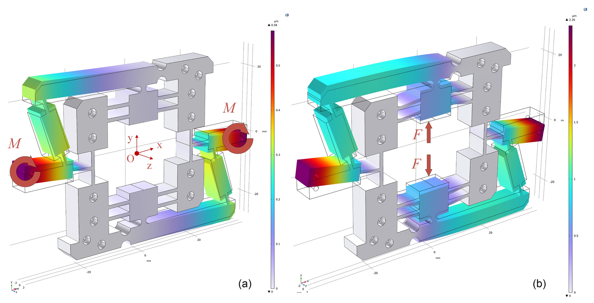
Table 6Rotational displacement performance. Retain three significant digits.

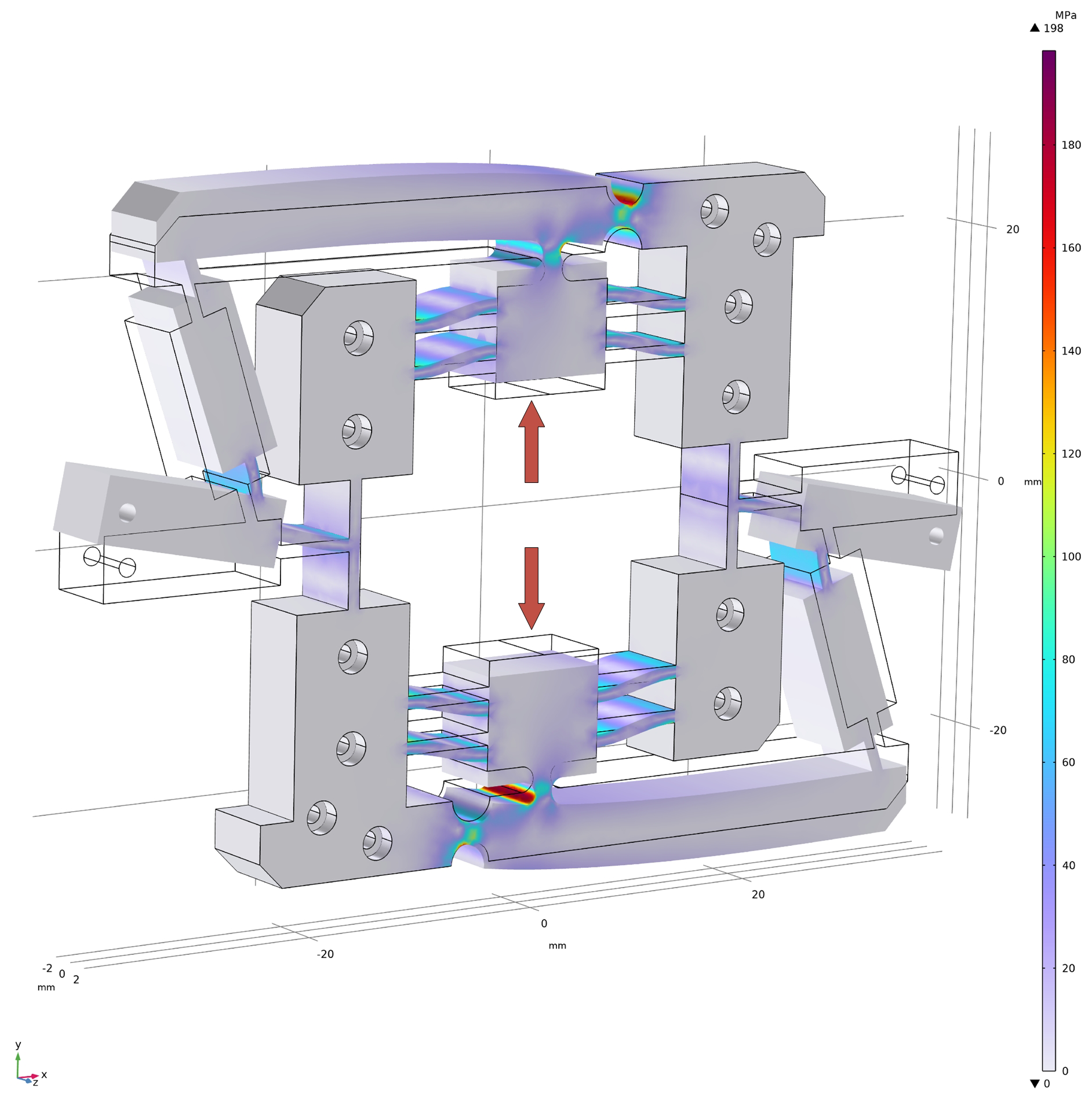
To evaluate the safety factor of the device, the maximum displacement of 28 µm was applied to the piezoelectric actuator. As shown in Fig. 12, the maximum stress in the mechanism is 198 MPa, which is well below the material's yield strength of 503 MPa. This results in a high factor of safety of .
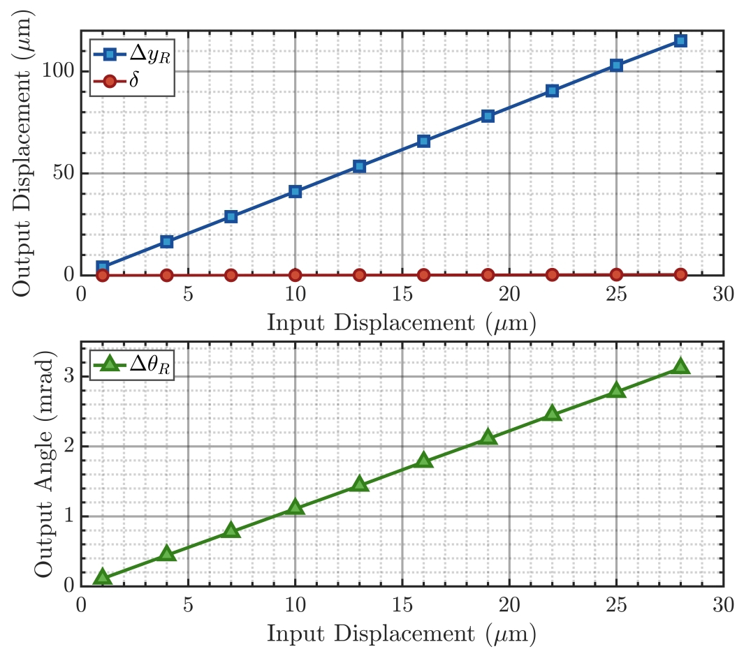
To evaluate the rotational angle and accuracy of the proposed mechanism, a parameter sweeping is implemented for the input displacement, as summarized in Table 6. The results demonstrate that under a 28 µm input displacement, the maximum rotational angle reaches 3.12 mrad. The maximum center offset is 0.424 µm. This indicates that the designed compliant mechanism exhibits excellent decoupling capability for rotational motion. Furthermore, the input–output relationship depicted in Fig. 13 shows a highly linear correlation between the output rotational displacement and the actuator input displacement.
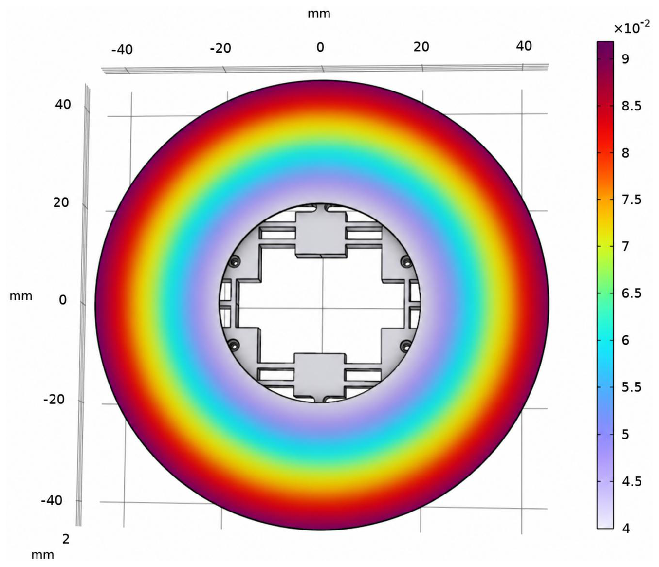
Figure 15Total displacement distribution of the end effector under a 28 µm input displacement.
Based on the requirements of the intended precision positioning application and relevant studies, the target operational bandwidth of the compliant rotational stage was set to 50 Hz. To represent the actual assembled configuration more accurately, both the end effector and the PZT actuator were included in the modal model. The end effector was modeled as a rigid domain with its actual mass, while the PZT actuator was represented by an equivalent axial stiffness of 60 N µm−1 together with its actual mass. During the eigenfrequency analysis, the prescribed displacement conditions used in the static analysis were deactivated, while the base constraints were retained.
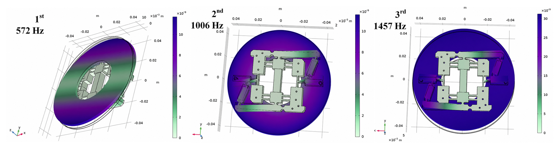
The first three natural frequencies of the assembled stage were 572, 1006, and 1457 Hz, respectively, and the corresponding mode shapes are shown in Fig. 14. Therefore, the first structural resonance is approximately 11.44 times higher than the target operational bandwidth, providing a sufficient frequency-separation margin for precision positioning.
Following the validation of the rotational compliant mechanism, the end effector was integrated into the design. The performance of the full assembly was then evaluated through simulation. As illustrated in Fig. 15, the end effector exhibits a uniform and symmetrical rotational motion, and its kinematic output shows close agreement with that of the compliant stage, confirming effective motion transmission.
Table 7Quantitative comparison of rotational performance between the baseline and proposed designs under an input displacement of 9 µm. Note: the parasitic displacements in X and Y are defined as the residual translational deviations of the output point (point R in Fig. 6) from an ideal pure circular trajectory.
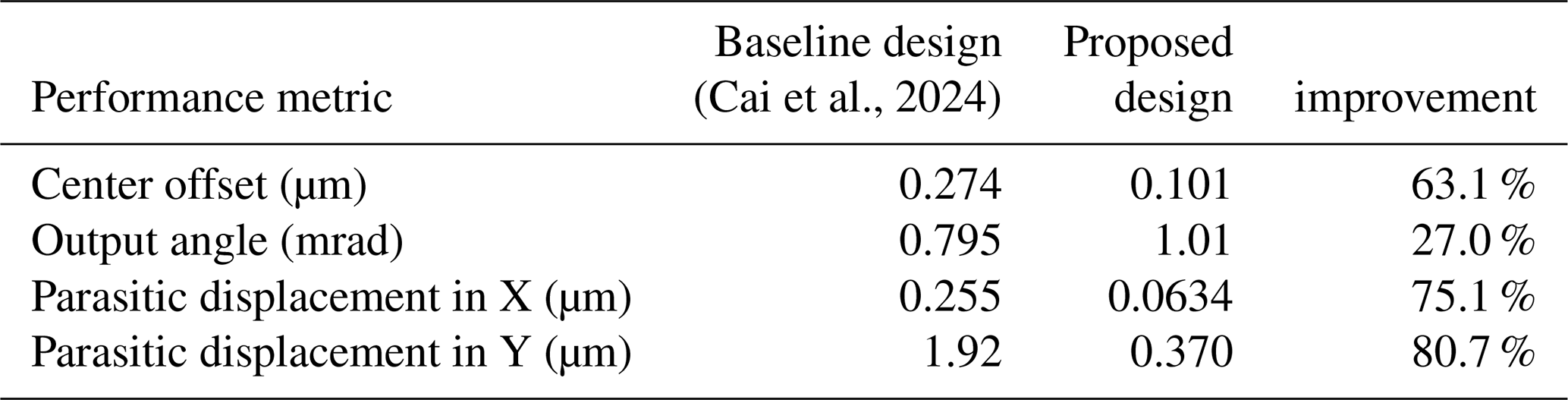
To quantitatively validate the effectiveness of the proposed self-compensation mechanism, a comparative study is conducted between the present design and the baseline two-stage lever amplification mechanism without compensation features (Cai et al., 2024). Both mechanisms are simulated under identical conditions (AL7075-T651, same mesh density, and boundary constraints) with an input displacement of 9 µm. The results are summarized in Table 7.
As shown in Table 7, the proposed mechanism reduces the center offset by 63.1 %, confirming the effectiveness of the non-vertical connecting beam and double-ended fixed flexure hinge in actively compensating for rotation center drift. The parasitic displacements in the x and y directions are suppressed by 75.1 % and 80.7 %. Meanwhile, the output rotational angle increases by 27.0 % (from 0.795 to 1.010 mrad) under the same input, demonstrating that accuracy improvement is achieved without sacrificing motion range. These quantitative results provide further numerical evidence that the proposed self-compensation mechanism effectively suppresses the parasitic translational coupling inherent in the baseline rotational compliant mechanism.
This study proposes a compact rotational compliant stage with structural self-compensation for rotation center offset. The stage adopts a centrosymmetric single-actuator configuration comprising two parallel branches, each consisting of a two-stage lever amplification mechanism and an input guidance mechanism. The combination of a non-vertical inter-stage connecting beam and a double-ended fixed flexure hinge produces a compensating displacement at the secondary lever, thereby reducing rotation center drift. The centrally arranged PZT actuator and symmetric guidance mechanisms also enable balanced load transmission between the two branches. A compliance-based analytical model was established by considering the rigid end-effector constraint and the displacement compatibility imposed by the PZT actuator. Pareto multi-objective optimization was subsequently performed to balance the rotational output and the center-offset indicator.
Under a prescribed relative input displacement of 28 µm, the optimized stage produces an output rotation of 3.12 mrad, with a maximum rotation center offset of 0.424 µm and a maximum von Mises stress of 198 MPa. The first natural frequency of the assembled stage, including the end effector and PZT actuator, is 572 Hz. With overall planar dimensions of 51 mm × 78 mm, the proposed stage achieves a favorable balance among rotational range, rotation center stability, structural compactness, and dynamic performance. A controlled comparison with the baseline two-stage lever mechanism further shows that the proposed configuration substantially reduces the rotation center offset and parasitic translational motion while increasing the output rotation under identical simulation conditions. These results provide additional numerical evidence for the effectiveness of the proposed self-compensation mechanism.
It should be noted that the present conclusions are based on analytical modeling and finite element simulations under idealized material, geometric, loading, and boundary conditions. Practical factors such as machining tolerances, assembly errors, PZT hysteresis and creep, preload variation, and off-axis actuation were not included in the current model. Prototype fabrication and experimental characterization will therefore be required to further evaluate the practical positioning accuracy and dynamic performance of the proposed stage.
Beyond its technical contributions, the proposed self-compensating compliant stage also carries broader significance in the context of the United Nations Sustainable Development Goals (SDGs). By enabling higher rotational precision and reduced parasitic motion within a compact, single-actuator architecture, the design supports advances in precision manufacturing, semiconductor alignment, and optical and biomedical instrumentation, contributing to SDG 9 (Industry, Innovation and Infrastructure).
The compliance components of the notch flexure are as follows.
Here, , r is the radius of the circular notch flexure hinge, t is the minimum thickness of the hinge at the center, and E is the Young's modulus of the material.
All the data used in this article can be made available upon reasonable request. Please contact Bingyu Cai (1002163746@ucsiuniversity.edu.my).
Conceptualization, Bingyu Cai and Mahmud Iwan Solihin; methodology, Bingyu Cai; validation, Bingyu Cai, Chaoran Chen, Xieben Wei, and Xujin Lu; formal analysis, Bingyu Cai and Hongyu Lin; investigation, Bingyu Cai and Yawen Zhao; resources, Bingyu Cai; data curation, Bingyu Cai and Zhe Lin; writing – original draft preparation, Bingyu Cai; writing – review and editing, Bingyu Cai and Mahmud Iwan Solihin; visualization, Bingyu Cai; supervision, Mahmud Iwan Solihin.
The contact author has declared that none of the authors has any competing interests.
Publisher's note: Copernicus Publications remains neutral with regard to jurisdictional claims made in the text, published maps, institutional affiliations, or any other geographical representation in this paper. The authors bear the ultimate responsibility for providing appropriate place names. Views expressed in the text are those of the authors and do not necessarily reflect the views of the publisher.
This research was supported by the Central Government Guidance Fund for Local Science and Technology Development (grant no. STKJ2024045), the Guangdong Provincial Program for Young Innovators in Higher Education Institutions (grant no. 2025KQNCX243), and the Guangdong Key Project in Artificial Intelligence (grant no. 2025ZDZX3100).
This paper was edited by Benliang Zhu and reviewed by Qasim Atiyah and two anonymous referees.
Baek, S. W., Cho, N. G., and Lee, D. H.: Fabrication of a piezoelectrically driven micropositioning 3-DOF stage with elastic body using a multi-material 3D printer, Rapid Prototyping J., 26, 1579–1591, https://doi.org/10.1108/RPJ-01-2019-0015, 2020.
Barber, S. K., Geckeler, R. D., Yashchuk, V. V., Gubarev, M. V., Buchheim, J., Siewert, F., and Zeschke, T.: Optimal alignment of mirror-based pentaprisms for scanning deflectometric devices, Opt. Eng., 50, 073602–073602-8, https://doi.org/10.1117/1.3598325, 2011.
Cai, B., Solihin, M. I., Lu, X., Xie, Z., Chen, C., Yang, D., and Zhao, Y.: Design of a Compact Rotational Compliant Stage with Two-stage Lever Amplification Mechanism, 2024 5th International Conference on Mechatronics Technology and Intelligent Manufacturing (ICMTIM), IEEE, 50–54, https://doi.org/10.1109/icmtim62047.2024.10629573, 2024.
Cai, B., Solihin, M. I., Chen, C., Lu, X., Xie, Z., and Yang, D.: Modeling of a nonlinear coupled compliant mechanism via developed kinematics-integrated neural network algorithm, Microsyst. Technol., 31, 407–419, https://doi.org/10.1007/s00542-024-05733-9, 2025.
Chen, F., Zhang, Q., Gao, Y., and Dong, W.: A review on the flexure-based displacement amplification mechanisms, IEEE Access, 8, 205919–205937, https://doi.org/10.1109/ACCESS.2020.3037827, 2020.
Clark, L., Shirinzadeh, B., Zhong, Y., Tian, Y., and Zhang, D.: Design and analysis of a compact flexure-based precision pure rotation stage without actuator redundancy, Mech. Mach. Theory, 105, 129–144, https://doi.org/10.1016/j.mechmachtheory.2016.06.017, 2016.
Gong, Z., Huo, D., Niu, Z., Chen, W., and Cheng, K.: A novel long-stroke fast tool servo system with counterbalance and its application to the ultra-precision machining of microstructured surfaces, Mech. Syst. Signal Pr., 173, 109063, https://doi.org/10.1016/j.ymssp.2022.109063, 2022.
Guo, Z., Zhao, P., Zhang, W., Tian, Y., and Hu, G.: Design and simulation of a single piezoelectric-driven rotary actuator with double-layer flexible mechanism, Actuators, 12, 231, https://doi.org/10.3390/act12060231, 2023.
Habibullah, H.: 30 years of atomic force microscopy: creep, hysteresis, cross-coupling, and vibration problems of piezoelectric tube scanners, Measurement, 159, 107776, https://doi.org/10.1016/j.measurement.2020.107776, 2020.
Huang, W.-W., Wang, X., Meng, Y., Li, L., Zhang, X., Ren, M., and Zhu, L.-M.: Design, modeling and control of high-bandwidth nano-positioning stages for ultra-precise measurement and manufacturing: a survey, Int. J. Extreme Manuf., 6, 062007, https://doi.org/10.1088/2631-7990/ad6ecc, 2024.
Jeong, S., Kim, G., and Cha, K. R.: A study on optical device alignment system using ultra precision multi-axis stage, J. Mater. Process. Tech., 187–188, 65–68, https://doi.org/10.1016/j.jmatprotec.2006.11.165, 2007.
Kim, H. and Gweon, D. G.: Development of a compact and long range XYθz nano-positioning stage, Rev. Sci. Instrum., 83, https://doi.org/10.1063/1.4740254, 2012.
Lee, C., Lee, J. W., Ryu, S. G., and Oh, J. H.: Optimum design of a large area, flexure based XYθ mask alignment stage for a 12-inch wafer using grey relation analysis, Robo. Cim-Int. Manuf., 58, 109–119, https://doi.org/10.1016/j.rcim.2019.02.005, 2019.
Li, H., Tang, H., Li, J., and Chen, X.: Design, fabrication, and testing of a 3-DOF piezo fast tool servo for microstructure machining, Precis. Eng., 72, 756–768, https://doi.org/10.1016/j.precisioneng.2021.07.015, 2021.
Mu, R., Lai, L., and Zhu, L.: Large range parallel compliant pure rotational micropositioning stage driven by two voice coil motors with symmetrical layout, Rev. Sci. Instrum., 96, https://doi.org/10.1063/5.0247588, 2025.
Qin, Y., Soundararajan, R., Jia, R., and Huang, S.-L.: Direct inverse linearization of piezoelectric actuator's initial loading curve and its applications in full-field optical coherence tomography (FF-OCT), Mech. Syst. Signal Pr., 148, 107147, https://doi.org/10.1016/j.ymssp.2020.107147, 2021.
Qu, J., Chen, W., Zhang, J., and Chen, W.: A piezo-driven 2-DOF compliant micropositioning stage with remote center of motion, Sensor. Actuat. A-Phys., 239, 114–126, https://doi.org/10.1016/j.sna.2016.01.025, 2016.
Wang, R. and Zhang, X.: A planar 3-DOF nanopositioning platform with large magnification, Precis. Eng., 46, 221–231, https://doi.org/10.1016/j.precisioneng.2016.04.016, 2016.
Wei, Y. and Xu, Q.: Design and testing of a new force-sensing cell microinjector based on soft flexure mechanism, IEEE Sensors J., 19, 6012–6019, https://doi.org/10.1109/JSEN.2019.2909533, 2019.
Yang, Z., Cai, B., Li, R., Peng, H., and Bai, Y.: A Novel Micro-Positioning Stage With Large-Stroke and Adjustable Stiffness, International Design Engineering Technical Conferences and Computers and Information in Engineering Conference, American Society of Mechanical Engineers, 85444, V08AT08A019, https://doi.org/10.1115/detc2021-70068, 2021.
Ye, T. and Li, Y.: Synthesis of 2-DOF decoupled rotation stage with FEA-based neural network, Processes, 11, 192, https://doi.org/10.3390/pr11010192, 2023.
Yong, Y. K.: Kinetostatic Modelling of Compliant Micro-motion Stages with Circular Flexure Hinges, PhD thesis, School of Mechanical Engineering, The University of Adelaide, http://hdl.handle.net/2440/48287 (last access: 29 September 2026), 2007.
Yong, Y. K. and Lu, T. F.: Kinetostatic modeling of 3-RRR compliant micro-motion stages with flexure hinges, Mech. Mach. Theory, 44, 1156–1175, https://doi.org/10.1016/j.mechmachtheory.2008.09.005, 2009.
Yu, H., Zhang, C., Yang, B., Chen, S.-L., Fang, Z., Li, R., and Yang, G.: The design and kinetostatic modeling of 3PPR planar compliant parallel mechanism based on compliance matrix method, Rev. Sci. Instrum., 90, https://doi.org/10.1063/1.5080252, 2019.
Zhu, X., Wen, Z., Chen, G., Liang, J., and Liu, P.: A decoupled flexure-based rotary micropositioning stage with compact size, P. I. Mech. Eng. C.-J. Mec., 232, 4167–4179, https://doi.org/10.1177/0954406217747640, 2018.