the Creative Commons Attribution 4.0 License.
the Creative Commons Attribution 4.0 License.
 | 25 Aug 2026
Two-dimensional point suspension characteristics of a magnetic robot driven by dual electromagnets within a fluid pipe
Zhanxiang Cui
Yonghua Lu
Yun Zhu
Manipulating microrobots within narrow conduits has significant potential in medical and industrial applications, including disease diagnosis and treatment within body lumens and inspection of fluid transport pipelines. To address the challenges of operating in fluid environments, this paper proposes a method for suspending a magnetic robot within the two-dimensional plane of a fluid conduit. Two vertically arranged electromagnets generate a non-uniform magnetic field that drives the magnetic ball. Hall sensors and visual measurement jointly provide positional feedback to the controller. The effects of drive current and fluid velocity on the levitation characteristics of the magnetic ball are investigated experimentally. Results indicate that, when the magnetic ball is suspended within the fluid pipe, higher fluid velocity or greater distance from the electromagnet axis results in larger horizontal displacement of the ball. Compared with a single-electromagnet drive, the dual-electromagnet drive effectively constrains the horizontal displacement of the magnetic ball and reduces fluctuations during fixed-point suspension. The horizontal deviation is reduced by up to 58 %. Maximum horizontal fluctuations decrease from 0.35 to 0.21 mm, while maximum vertical fluctuations decrease from 0.20 to 0.11 mm. Furthermore, by adjusting the current of each electromagnet, the magnetic ball achieves precise point suspension and stepwise motion within a confined fluid domain, with position control errors below 0.1 mm. The dual-electromagnet drive demonstrates superior performance in positioning control of the magnetic ball, providing a robust basis for future applications.
- Article
(10432 KB) - Full-text XML
-
Supplement
(52444 KB) - BibTeX
- EndNote


With advances in micromanufacturing, nanomanufacturing, and automatic-control technologies, microrobots are being increasingly deployed to replace labor-intensive manual operations and to operate in complex, demanding environments. Among these, pipeline microrobots have demonstrated significant application value in both medical and industrial inspection fields (Jang et al., 2022). The human body contains numerous tubular organs, such as the gastrointestinal tract and blood vessels, where diseases often require interventional examination and treatment. Traditional interventional diagnostic and therapeutic methods suffer from poor controllability, invasiveness, and stringent spatial requirements (Yang et al., 2025). Consequently, researchers have explored the use of microrobots within cavities inaccessible to manual operation. The development of diagnostic and therapeutic devices based on micro-electro-mechanical systems (MEMSs) is emerging as a research hotspot (Cai et al., 2022; Schmitt et al., 2020; Hale et al., 2014). Currently, researchers employ electric, magnetic, chemical, biological, and mechanical propulsion methods to drive microrobots through bodily lumens, enabling functions such as minimally invasive surgery, drug delivery, biopsy, and cell characterization (Elnaggar et al., 2024).
Industrial pipelines transport various liquids, including oil, gas, and water. After prolonged operation, pipelines are susceptible to developing imperceptible cracks, corrosion, blockages, and other defects (Zheng et al., 2022). To detect and repair such issues, pipeline inspection robots are employed. When operating within fluid-filled pipelines, these robots must overcome fluid resistance, and their performance is influenced by factors such as the fluid environment, pipeline dimensions and geometry, and the drive mechanism. Typically, pipeline inspection robots utilize wheels, tracks, legs, or tow cables for locomotion (Elankavi et al., 2022). They must maintain continuous contact with the pipe wall during operation, with their movement being constrained by wall friction and the presence of adhered debris on the wall surface.
Researchers have explored propulsion technologies for microrobots navigating fluid tubes. Among these, magnetic field propulsion shows significant promise for applications within human tubular organs and small industrial pipelines due to its wireless and non-invasive nature (Sun et al., 2023). Microrobots can be powered and controlled by external magnetic fields, enabling smaller sizes and improved maneuverability. Rotating magnetic fields generated by coils are commonly used to propel microrobots in a spiral motion through liquid conduits. For instance, Qin et al. (2023) utilized Helmholtz coils to generate rotating magnetic fields driving microrobots within mucus tubes. Through simulations and experiments in conduits with diameters exceeding 20 mm, the study investigated the influence of magnetic field frequency, conduit diameter, and flow rate on the forces acting on the microrobots and their movement speeds. Liang et al. (2015) employed rotating magnetic fields to propel helical robots through fluid conduits, experimentally determining the maximum speeds of microrobots under both downstream- and upstream-flow conditions in vertical and horizontal pipes. However, rotating magnetic fields produce relatively weak torques and require complex equipment (Yunas et al., 2020). Additionally, microrobots pose a risk of contacting pipe walls during rotation.
Magnetic-levitation (maglev) technology, owing to its advantages of contactless actuation, the absence of mechanical friction, high-precision positioning, and low noise, has enabled transformative applications across multiple engineering domains. In the biomedical field, electromagnetic levitation has been successfully employed for label-free single-cell manipulation and sorting (Ramarao et al., 2025). In the aerospace sector, maglev technology is well-suited for non-contact, high-precision manipulation of devices in vacuum environments (Tayebi et al., 2023; Fallahiarezoodar and Zhu, 2025). For instance, Bian et al. (2026) employed magnetically suspended spherical actuators to reduce appendage vibrations and external disturbances in satellite attitude control systems. In semiconductor manufacturing, maglev stages have become essential positioning equipment in precision fabrication processes (Joo et al., 2026). In contrast to conventional uniform or rotating magnetic fields used as drive sources, active electromagnetic levitation employs electromagnets to generate gradient magnetic fields, thereby enhancing load capacity and expanding the operational range (Liu et al., 2024). This approach enables microrobots to move through pipelines without relying on supporting structures or propulsion mechanisms. For instance, Zhang et al. (2019) and Liu et al. (2023) developed one-dimensional and two-dimensional active magnetic-levitation systems capable of driving miniature permanent magnets to achieve suspension and motion over extended distances within empty conduits. During movement, the microrobots maintain precise positioning while avoiding contact with the pipe walls. Qu et al. (2021) and Malchikov et al. (2025) utilized external magneto-actuators to drive magnetic microrobots within liquid conduits, enabling rapid reciprocating motion in fluid environments (Ali et al., 2017). Although this method achieves high speed and impact force, it requires contact with the tube wall for structural support.
Building upon active magnetic-levitation drive technology, this paper proposes a method for manipulating magnetic robots within fluid pipelines. A magnetic-levitation system coupled with external symmetrical dual electromagnets serving as actuators enables controlled suspension and movement of robots within the pipes. The gradient magnetic field generated by the electromagnets provides a stronger driving force and a wider manipulation range for the magnetic robot. The external driver can move while carrying the robot. Precise positional adjustments of the ball are achieved through current control of the two electromagnet sets, maintaining non-contact with the pipe wall. Furthermore, experiments were conducted within the fluid pipe to investigate the effects of parameters such as fluid flow velocity and drive current on the ball's suspension performance. The study evaluates the robot's positional variation patterns, stability, and motion performance while comparing the differences in performance between single-electromagnet and dual-electromagnet drive configurations.
2.1 System design
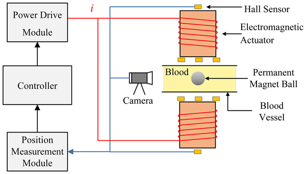
To simulate the scenario of remotely controlling robots within fluid pipelines, Fig. 1 presents a schematic diagram of the magnetic drive system for the robot inside fluid conduits. The external actuators are distributed along the length of the pipe on both sides to control the behavior of the internal robot. The core component of the system is a magnetic-levitation ball system, composed of magnetic balls, a controller, a drive circuit module, a position measurement module, two electromagnets, and a fluid pipe. The electromagnets generate an external magnetic field to drive the movement of micro-devices. The magnetic ball serves as a robot for operations within a fluid-filled pipeline, while the electromagnets, along with the associated power supply module and control module, serve as external actuators. The magnetic balls act as the controlled suspended objects, attracted by electromagnetic forces produced by the upper and lower electromagnets. The controller regulates the drive circuit to supply the appropriate current to the electromagnets, while the measurement circuit employs Hall position sensors and industrial cameras to provide positional feedback to the controller.
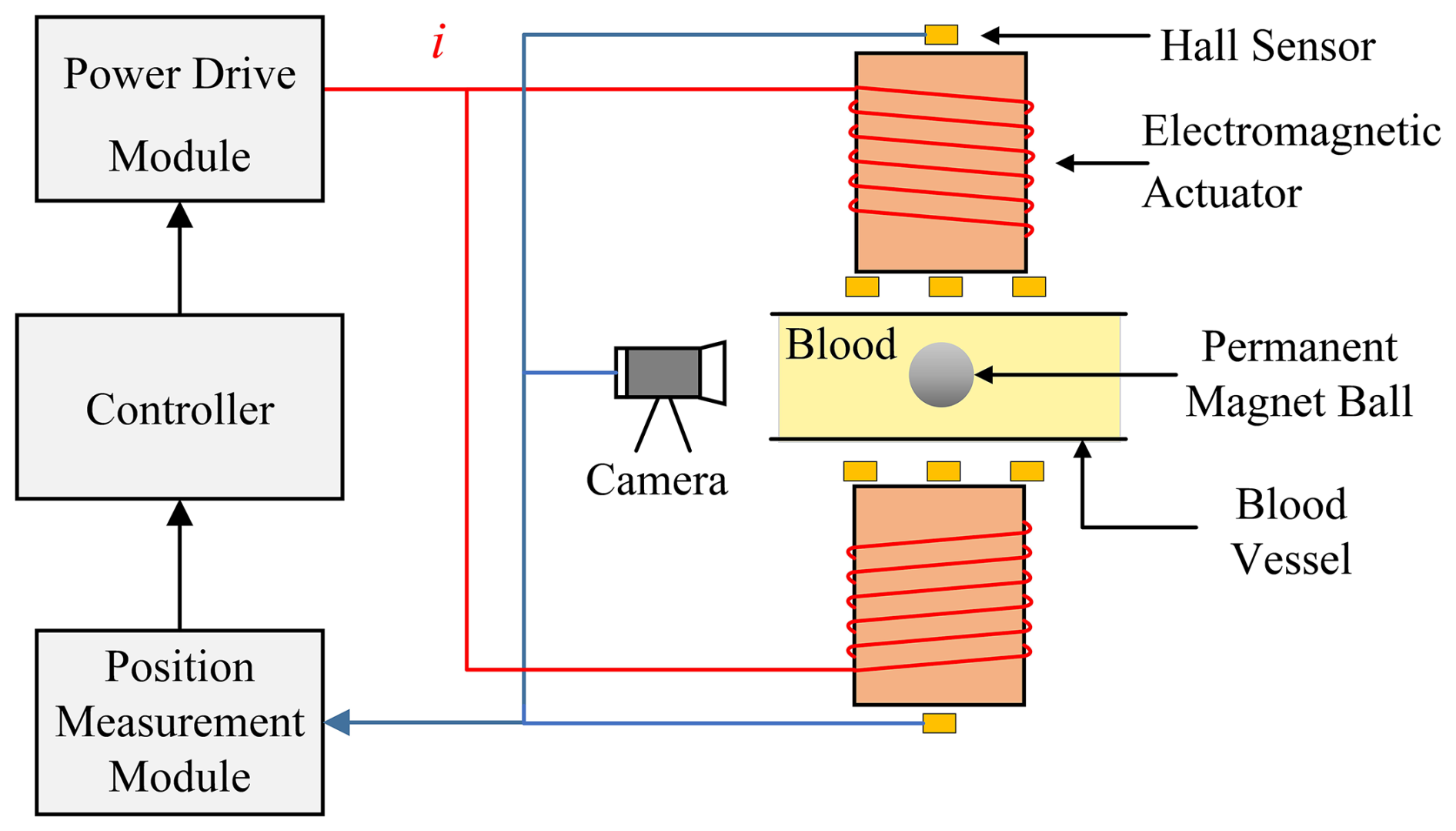
The robot is a spherical permanent magnet made of NdFeB. Compared with iron or steel balls, it generates a greater magnetic moment per unit volume, enabling stronger electromagnetic attraction. Moreover, spherical robots experience reduced resistance when moving through fluids and exhibit improved navigational stability when traversing diverse directions. The north pole (N) and south pole (S) of the permanent magnet are situated on two hemispherical surfaces. The magnetic ball has a diameter of 13 mm, a mass of 8.15 g, and a surface magnetic flux density of 677.3 mT.
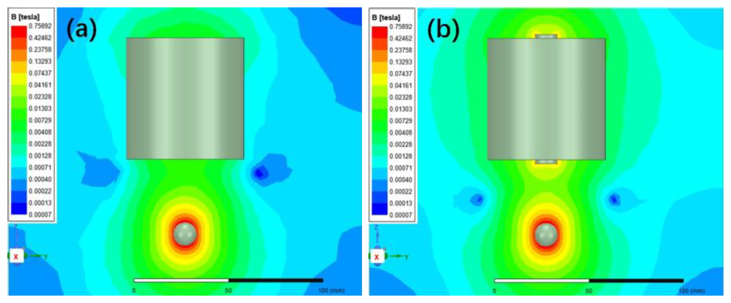
Figure 2Magnetic field contour plots for the coreless and core-equipped magnetic-levitation models at a current of 0.5 A and a suspension distance of 40 mm.
Electromagnets used in industrial applications typically feature a multi-layer solenoid structure with an iron core (Ruan et al., 2022). The iron core increases the magnetic field density along the electromagnet's axis, thereby enhancing the attractive force exerted on ferromagnetic materials. However, the inclusion of an iron core changes the current characteristics of the electromagnet. A model of an electromagnetically levitated ball was created in Ansys Electronics software. The suspension characteristics of electromagnets with and without cores in water were analyzed and compared, as shown in Fig. 2a and b, respectively. In the simulation model, the current in the coil flows counterclockwise, and the north pole of the magnetic ball points vertically upward. The structural parameters of the electromagnet coil are presented in Table 1. The electromagnet core, measuring Φ 12 mm × 69 mm, is symmetrically positioned at the center of the coil.
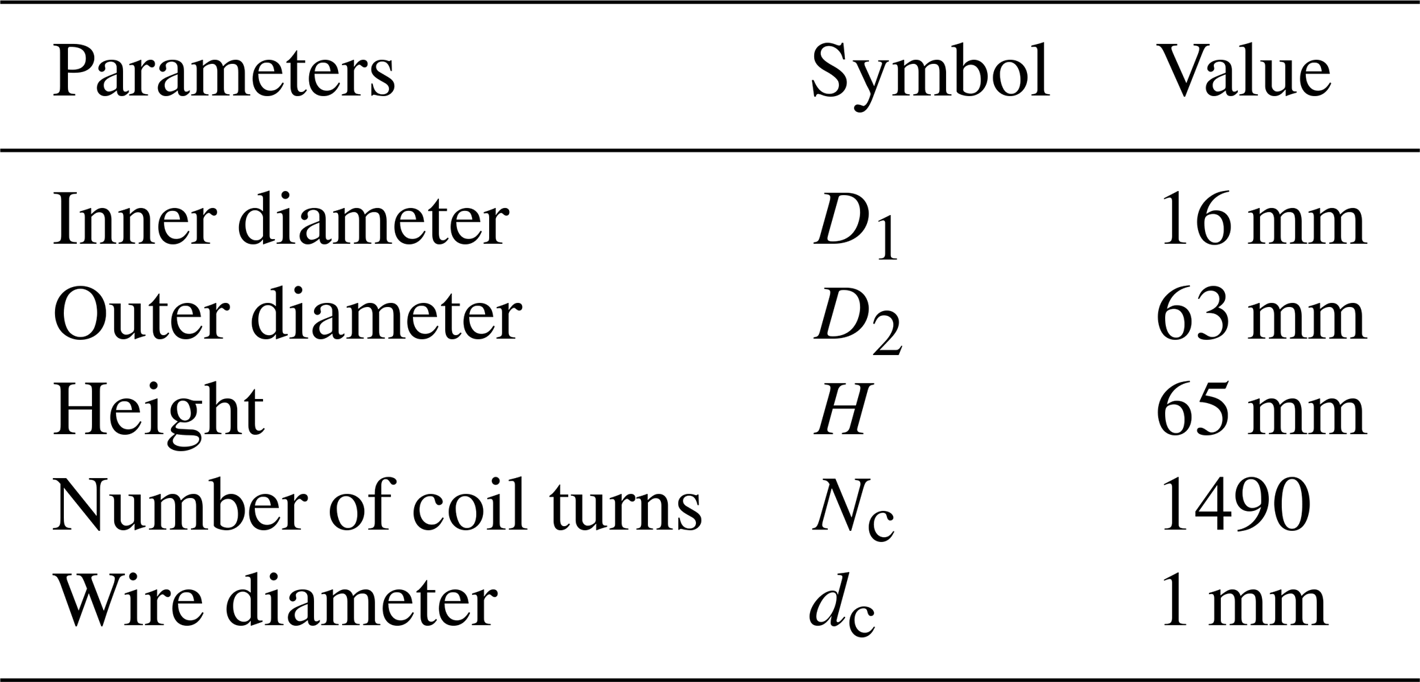
Figure 2 presents the contour plots of the magnetic field, illustrating the field strength distributions for both the coreless and core-equipped models at a current of 0.5 A and a suspension distance of 40 mm. As shown in Fig. 2b, under identical operating conditions, the addition of an iron core increases the magnetic field strength along the axis of the electromagnet, thereby enhancing its electromagnetic attraction.
When the magnetic ball is stably suspended, the electromagnetic force and gravitational force are balanced. Therefore, the relationship between the coil current and the suspension distance at force equilibrium was calculated, as shown in Fig. 3. As shown in Fig. 3, an electromagnet with a core requires a lower current to maintain the same suspension distance. However, the controllable current range is narrower for the same range of distances in the core-equipped design. This implies that finer adjustment resolution becomes necessary for small variations in the suspension distance. According to Fig. 3, the average change in suspension distance per unit change in current is 0.1 mm mA−1 for the coreless electromagnet compared with 0.26 mm mA−1 for the core-equipped electromagnet. Given that the adjustment resolution of the actual current driver is 0.001 A, a coreless electromagnet structure was chosen to achieve higher positional adjustment accuracy for the magnetic ball. Additionally, in the dual-electromagnet drive configuration, the upper and lower electromagnets have identical designs.
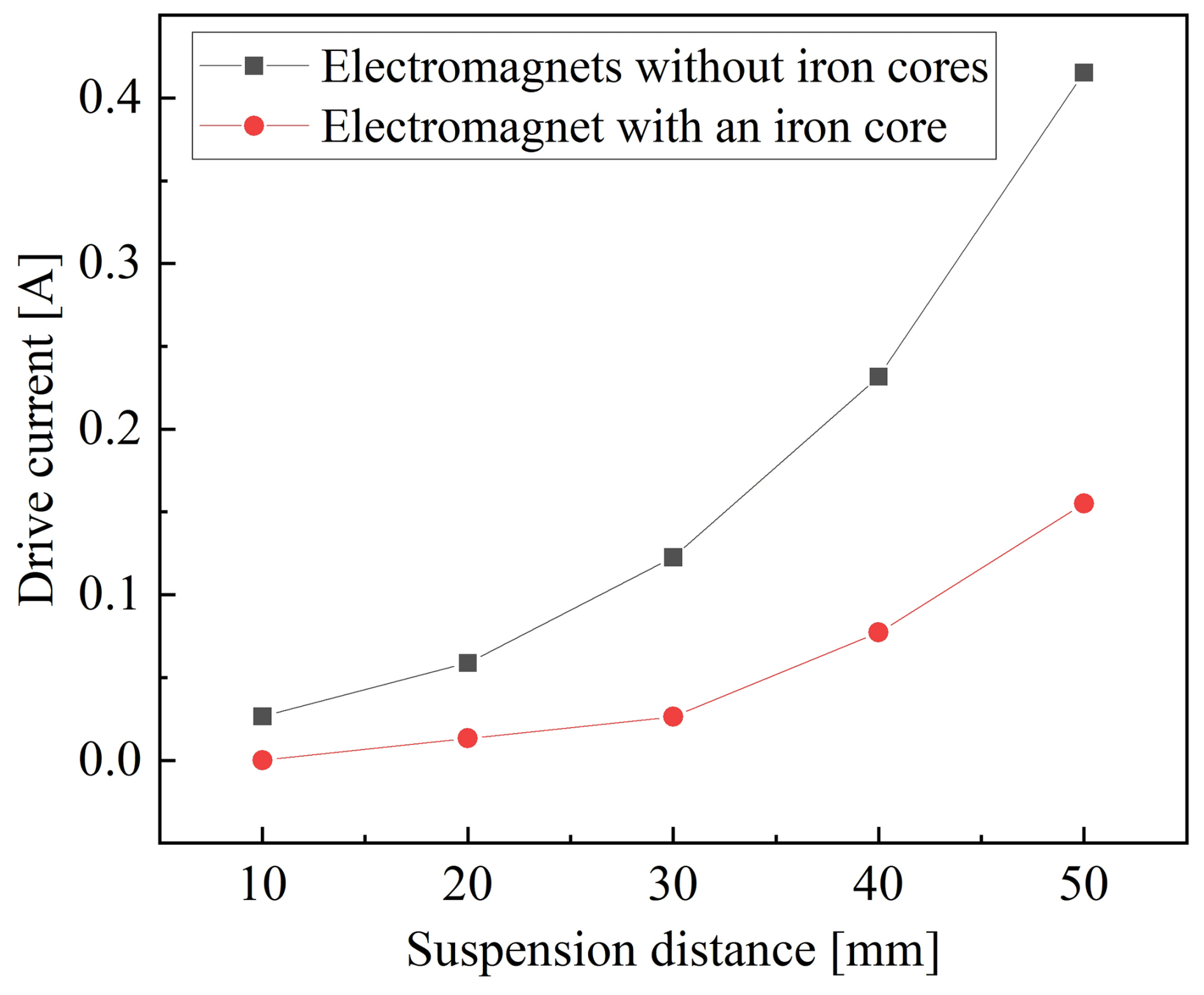
Figure 3Relationship between coil current and suspension distance for the coreless and core-equipped magnetic-levitation models at equilibrium.
2.2 Method for position measurement of a magnetic ball
The primary method for accurately measuring the ball's position employs an industrial camera, supplemented by a Hall sensor as an auxiliary positioning device. The industrial camera uses a CMOS sensor to capture the ball's images at a frame rate of 30 fps with a resolution of 1296 × 964 pixels. It captures real-time images of the ball, processes them using OpenCV, and recognizes the ball's center position in both the horizontal and the vertical directions. Additionally, a Hall sensor is mounted on the end face of the electromagnet to measure the distance between the magnetic ball and the electromagnet, providing supplementary location information. The coarse position data from the Hall sensor serve to verify the position obtained through visual measurement and acts as a backup positioning method when visual measurement is unavailable.
The image processing workflow consists of preprocessing, ball recognition, and position calculation. After the camera captures an image of the magnetic ball, the image undergoes preprocessing steps, including binarization and Gaussian filtering. Subsequently, contour recognition is performed on the magnetic ball image. When viewed externally through the fluid pipe, the magnetic ball's image appears distorted into an approximate ellipse. Therefore, the system is programmed to search for elliptical contours within the image, filtering them based on perimeter, area, and axis length to identify the magnetic ball's outline. Finally, distortions in the shape and position of the magnetic ball's image contour are corrected, and camera lens distortion is eliminated. The center coordinates of the magnetic ball are then calculated to provide its positional information.
When the drive current of the electromagnet varies, the electromagnetic force acting on the magnetic ball changes, causing the ball to reach a state of force equilibrium at different positions. When the fluid velocity is constant, adjusting the drive current of the electromagnet can modify the suspension position of the ball within the pipe. At the same time, changing the flow rate enables the magnetic ball to establish a new equilibrium at a different position. Figure 4 illustrates a schematic diagram of the force analysis of the magnetic ball in a fluid pipe, where both the upper and lower electromagnets exert an attractive force on the magnetic ball. The alteration of the current in the upper and lower electromagnets results in a change in the equilibrium state of the magnetic ball within the fluid, consequently modifying its behavior. The position of the magnetic ball shifts within the zOy plane while remaining on the pipe's symmetrical plane.
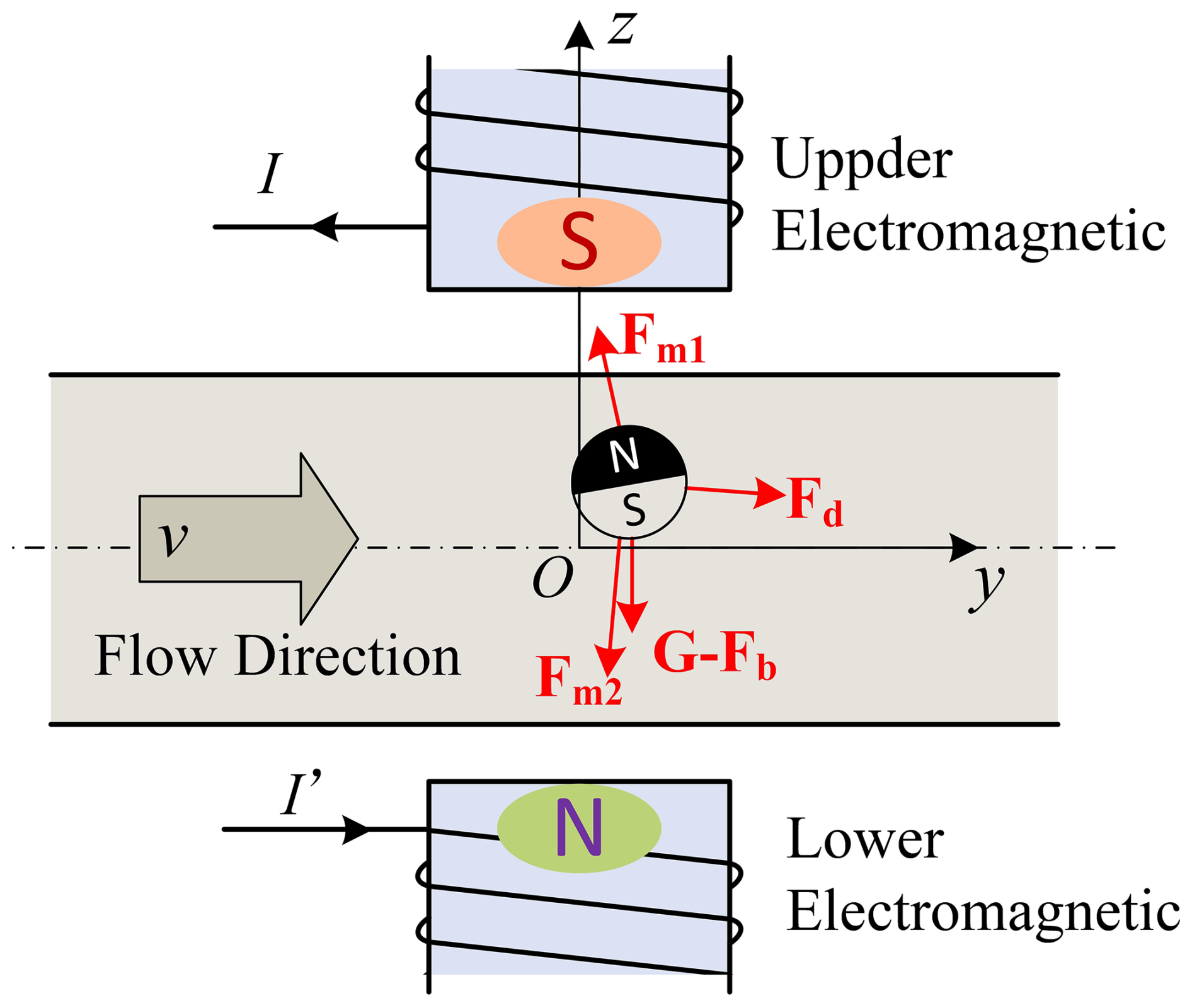
The magnetic ball is subjected to fluid resistance, buoyancy, and gravity within the pipe flow. The electromagnetic force exerted on the magnetic ball by the upper electromagnet can be expressed as follows (Belharet et al., 2012):
The electromagnetic force exerted on the magnetic ball by the lower electromagnet can be expressed as follows:
where the magnetic moment of the magnetic ball is denoted by p; B1 and B2 represent the magnetic flux densities generated by the upper and lower electromagnets, respectively; ∇ denotes the Nabla operator; the surface magnetic induction of the magnetic ball is denoted by Bs; the magnetic permeability of air is denoted by μ0; and Vb denotes the volume of the magnetic ball. j and k represent the unit vectors along the y axis and z axis, respectively.
The gravitational force acting on the magnetic ball is as follows:
The buoyancy force acting on a magnetic ball in a fluid is as follows:
Magnetic spheres in a fluid experience two types of fluid resistance: viscous resistance caused by friction, which can be expressed as
and pressure differential resistance caused by fluid pressure (Yesin et al., 2006), which can be expressed as
The total fluid resistance is as follows:
where m represents the mass of the magnetic ball, g indicates the gravitational acceleration, ρ represents the density of the fluid, η refers to the viscosity of the fluid, R signifies the radius of the magnetic ball, v is the fluid velocity, ζ is the drag coefficient, and A is the projected area of the ball perpendicular to the direction of flow.
Experiments on the point suspension of a magnetic ball driven by an external magnetic field within a fluid pipe were conducted. Figure 5 shows the physical configuration of the experimental setup. A transparent pipeline with an inner diameter (Dv) of 22 mm was used, while a mixture of glycerin and water was employed to simulate a viscous fluid. This mixture has a density of 1060 kg m−3 and a dynamic viscosity of 0.0035 Pa s. A diaphragm pump drives the fluid through the pipeline, and its flow rate is adjustable. A pitometer is used to measure the velocity of the fluid in the pipeline. Electromagnets were strategically positioned on both sides of the fluid pipe. A gap of 30 mm (h1) was maintained between the center of the pipe and the bottom surface of the upper electromagnet coil, while a gap of 33 mm (h2) was maintained between the center of the pipe and the lower electromagnet coil. The magnetic suspension ball system consists of electromagnets, a drive circuit, a controller, and a power supply, enabling the magnetic ball to achieve stable point suspension within the fluid pipe under a specified supply current.
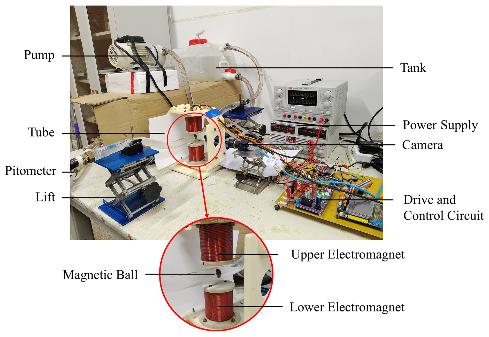
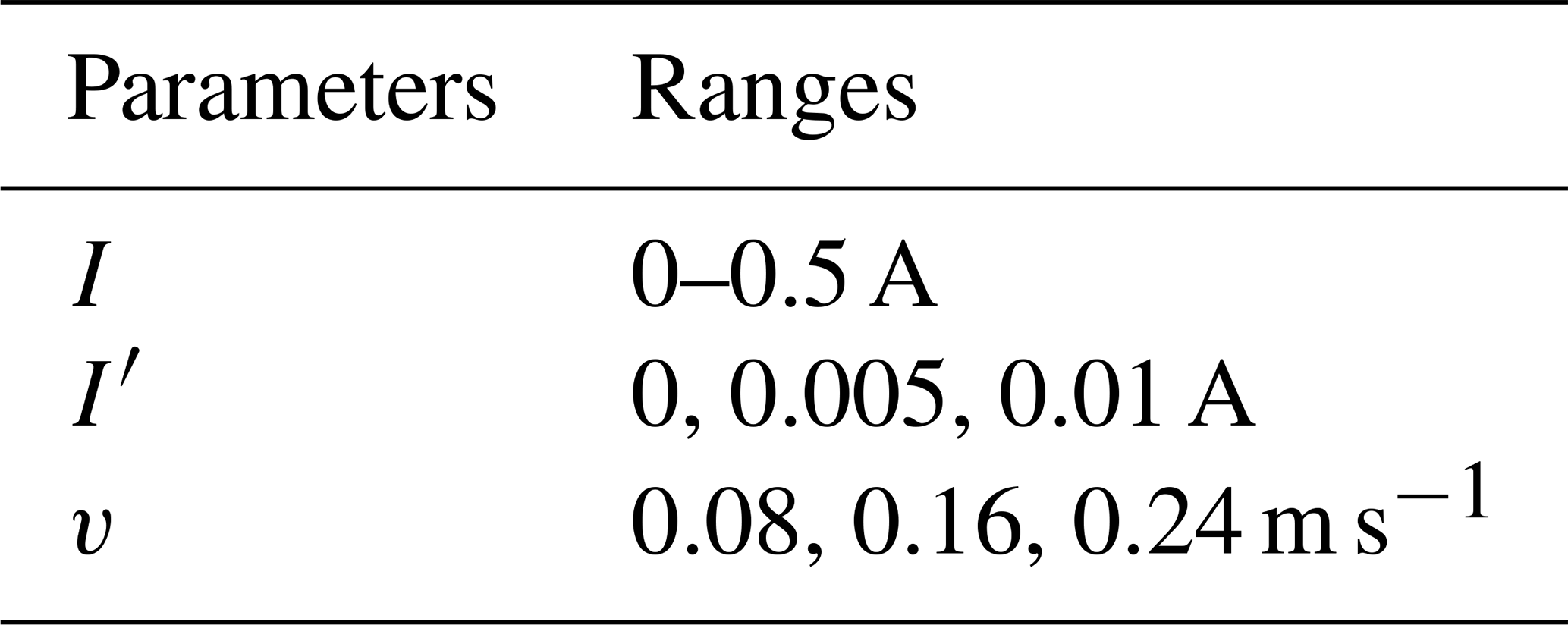
Figure 6 presents a schematic diagram illustrating the influencing parameters of the magnetic-levitation ball system within a fluid-filled circular tube. The primary parameters examined include the electromagnetic coil drive currents (I and I′) and the fluid flow velocity (v), which are manipulated to assess their effects on the levitation characteristics of the magnetic ball. The parameter ranges are listed in Table 2. In Fig. 6, a coordinate system is established, with the y axis aligned along the pipe axis and the z axis aligned with the electromagnetic coil axis. The position of the magnetic ball is denoted by its center coordinates Pm (0, ym, zm).
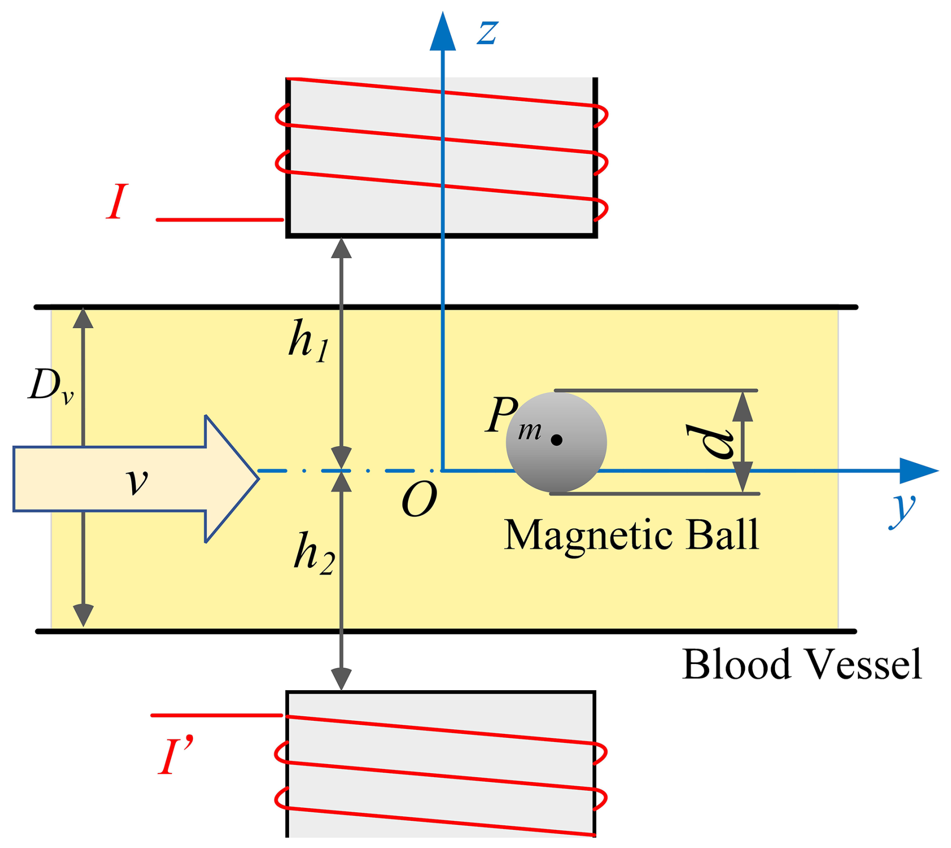
The suspension trajectory of the magnetic ball remains within a vertical yOz plane. The vertical position range of the magnetic ball within the fluid pipe extends from −4 to 4 mm, with higher values indicating higher positions. The drive methods for the magnetic ball are classified into single-electromagnet drive and dual-electromagnet drive. Dual-electromagnet systems generate stronger electromagnetic forces, allowing for performance comparison with existing literature (Cui et al., 2025). In a single-electromagnet drive, the magnetic ball is driven solely by the upper electromagnet. In a dual-electromagnet drive, both the upper and lower electromagnets are energized to drive the magnetic ball. The current I represents the drive current of the upper electromagnet, which is adjusted according to changes in the actual suspension position. The current I′ represents the drive current of the lower electromagnet; when , this indicates that the lower electromagnet is not operational, signifying single-electromagnet drive.
5.1 Characteristics of magnetic ball's point suspension
Flow in the pipe influences the behavior of the magnetic ball. Figure 7 presents photographs of the magnetic ball stably suspended in both stationary and flowing fluids. The green line in Fig. 7 denotes the central axis of the electromagnet and the pipe, serving as a reference. The elliptical red line and the “+” symbol indicate the ball's outline and center position, respectively. The elliptical appearance of the ball's outline results from visual distortion caused by the cylindrical shape of the pipe. Figure 7a shows that the magnetic ball driven by a single electromagnet is suspended within a stationary fluid. The magnetic ball is located at the origin of the coordinate system and lies on the same axis as the electromagnets. As illustrated in Fig. 7b, the drive current remains constant while the fluid flows at a constant velocity. The stable suspension position of the magnetic ball is altered by the impact of the fluid. The ball deviates to the right of the electromagnet's axis, while its vertical position shifts slightly upward.
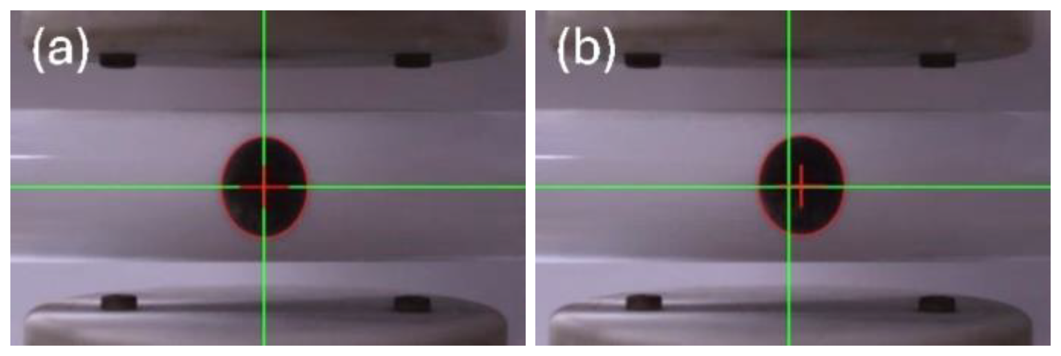
Figure 7Photograph of a magnetic ball suspended in a fluid pipe. (a) v=0 m s−1, A. (b) v=0.24 m s−1, A.
Subsequently, the position of the magnetically levitated ball within the fluid was analyzed under conditions of single-electromagnet drive and dual-electromagnet drive. The vertical suspension position of the magnetic ball was actively regulated through current adjustment, whereas the horizontal suspension position served as the dependent variable. The gray, purple, and yellow backgrounds in Fig. 8 represent the suspension zones accessible to the magnetic ball at different flow velocities, respectively. The suspension zones corresponding to flow velocities of 0.16 and 0.24 m s−1 overlap in the lower section of the pipe. Figure 8 illustrates the positional changes in the point suspension of magnetic balls within a fluid pipe at varying fluid flow velocities and drive currents. As depicted in Fig. 8, fluid velocity is the primary factor influencing the horizontal position of the magnetic ball. At low fluid velocities, the horizontal displacement of the magnetic balls is minimal. Specifically, at a fluid velocity of 0.08 m s−1, the horizontal position of the magnetic ball is approximately 0.6 mm. When the fluid flow velocity increases to 0.16 m s−1, the horizontal position of the magnetic ball ranges from 1 to 2.3 mm. At a fluid velocity of 0.24 m s−1, the horizontal position range expands further to between 1.4 and 4.3 mm, indicating a significant increase.
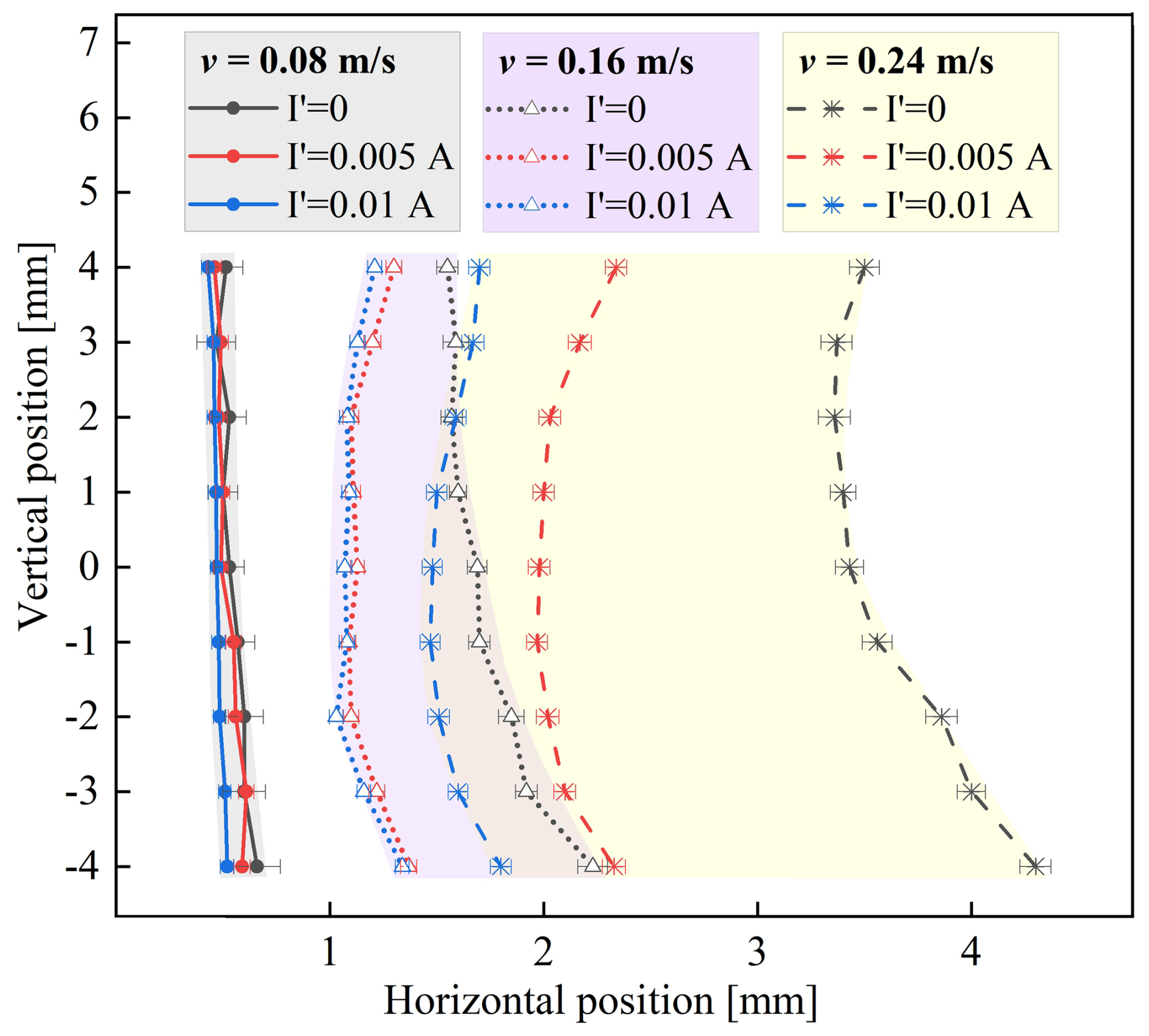
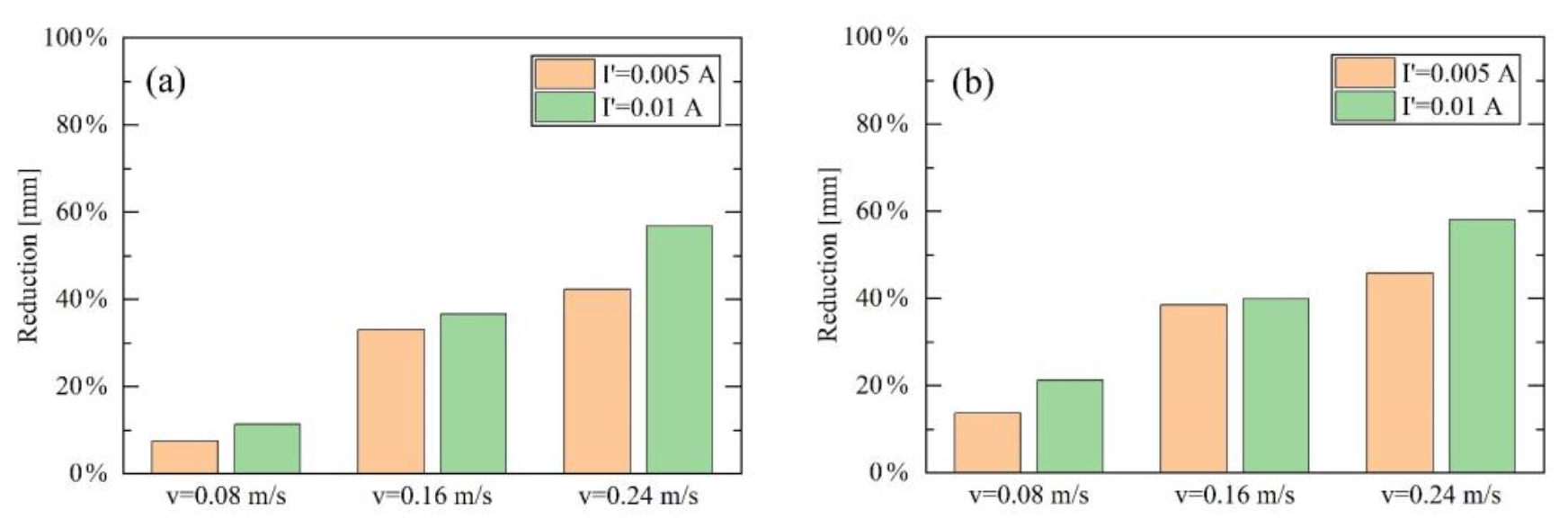
Figure 9Percentage reduction in the horizontal position of the magnetic ball driven by dual electromagnets. (a) At the midsection of the pipe (z=0 mm). (b) At the bottom of the pipe ( mm).
When the flow velocity is constant, the horizontal position of the magnetic ball is significantly reduced when using dual-electromagnet drive compared with a single-electromagnet drive (), particularly at a high flow velocity of 0.24 m s−1. Under dual-electromagnet drive conditions, an increase in the drive current of the lower electromagnet results in a decrease in the horizontal displacement distance of the magnetic ball. Figure 9 shows the reduction ratio of the horizontal position of the magnetic ball under dual-electromagnet drive at the midsection and bottom of the pipe. As depicted in Fig. 9, the higher the fluid velocity, the greater the reduction ratio of the horizontal position. At a flow velocity of 0.08 m s−1, the horizontal-displacement distance of the magnetic ball can be reduced by approximately 21 %, with the horizontal position of the magnetic ball at the bottom of the pipe decreasing from 0.7 to 0.5 mm. At a flow velocity of 0.24 m s−1, the maximum reduction in the horizontal displacement distance of the magnetic ball can reach approximately 58 %, with the horizontal position of the magnetic ball at the bottom of the pipe decreasing from 4.3 to 1.8 mm. When the driving current of the lower electromagnet is increased from 0.005 to 0.01 A, the reduction ratio of the horizontal position of the magnetic ball improves, with a more pronounced enhancement observed at the high flow velocity of 0.24 m s−1.
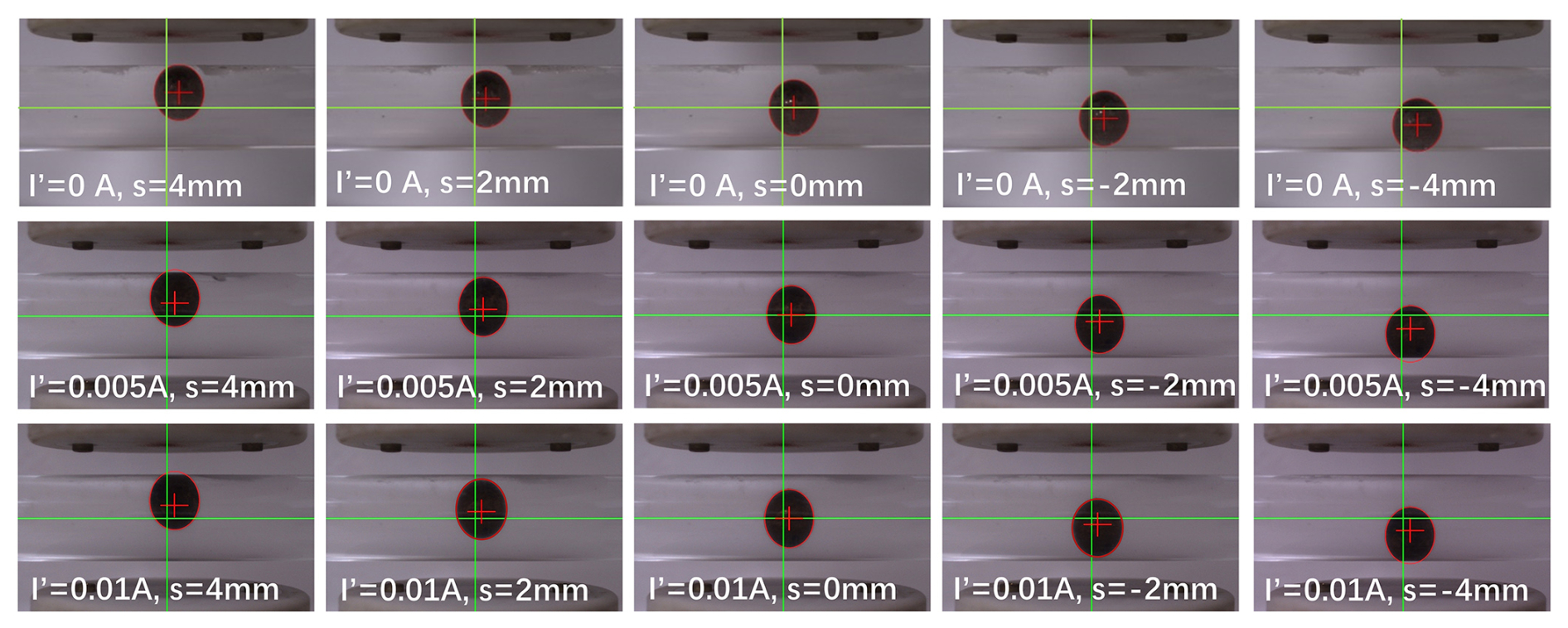
Figure 10 presents photographs of a magnetic ball suspended at varying heights, driven by single electromagnet and dual electromagnets, at a fluid flow velocity of 0.24 m s−1. As shown in Fig. 10, the fluid flow causes the magnetic suspension balls to deviate to varying degrees from the axis of the electromagnets. Figure 10 illustrates that the horizontal deviation of the magnetic ball from the vertical axis decreases as the system transitions from a single-electromagnet drive to a dual-electromagnet drive. Furthermore, as the current of the lower electromagnet increases, the horizontal deviation decreases even further.
As shown in Fig. 10, when driven by a single electromagnet, the horizontal position of the magnetic ball gradually increases as the suspension height decreases. At the bottom of the pipe, the horizontal displacement of the magnetic ball reaches its maximum. However, after the addition of the lower electromagnet, the horizontal displacement of the magnetic ball is significantly reduced, with a greater reduction at the bottom of the pipe compared to the top. For instance, with a flow velocity of 0.16 m s−1 and a current I′ of 0.005 A, the horizontal displacement of the magnetic-levitation ball at the center of the pipe decreased by 33 %, changing from 1.7 to 1.1 mm, in comparison with the single-electromagnet drive. Additionally, the horizontal displacement of the magnetic-levitation ball at the bottom of the pipe decreased by 39 %, changing from 2.3 to 1.4 mm. Consequently, under the dual-electromagnet drive, the horizontal position of the magnetic ball initially decreases and then increases as the suspension height decreases, reaching its minimum near the center of the pipe.
Experimental results indicate that fluid flow velocity is the primary factor influencing the horizontal position of the magnetic-levitation ball. As flow velocity increases, the horizontal impact force on the magnetic ball also increases, leading to greater horizontal displacement. In comparison with a single-electromagnet drive, a dual-electromagnet drive effectively constrains the horizontal displacement of the magnetic ball at higher fluid velocities. This is because the dual electromagnets provide a larger horizontal component of the electromagnetic force, which mitigates the influence of fluid forces. Increasing the current of the electromagnet enhances the constraint of the electromagnet set on the magnetic ball.
When using a single-electromagnet drive, the magnetic ball exhibits a larger horizontal displacement when suspended at a lower position. However, the dual-electromagnet drive significantly limits this phenomenon, allowing the magnetic-levitation ball to maintain a smaller displacement even at lower positions. This occurs because the magnetic ball is closer to the lower electromagnet at lower positions, resulting in a stronger electromagnetic force and enhanced positional stability.
5.2 Suspension stability of magnetic ball
In the preceding analysis, the horizontal position of the magnetic-levitation ball within the fluid pipe is relatively close to the axis of the pipe. Given that robots are less likely to damage the pipe wall when operating at a close distance from it, the area near the pipe's axis represents the optimal operating position. Consequently, the suspension stability of the magnetic-levitation ball at the center of a fluid pipe was investigated.
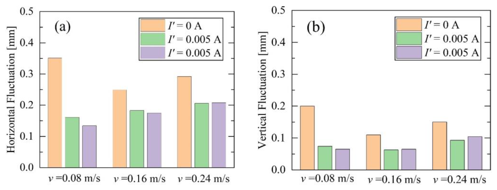
Figure 11Fluctuations of the magnetic-levitation ball at the center of pipes under different conditions. (a) Horizontal fluctuations. (b) Vertical fluctuations.
Figure 11 shows the fluctuations in the horizontal and vertical positions of the magnetic ball under varying fluid flow velocities and drive modes. Fluctuation refers to the range of variation in the position of the magnetic ball during stable suspension. Figure 12 specifically illustrates the positional changes of the magnetic ball at a flow velocity of 0.24 m s−1, while it is suspended at the center of the pipe. As shown in Fig. 11, the horizontal position fluctuations of the magnetic ball during suspension are greater than the vertical fluctuations. With the addition of the lower electromagnet or an increase in its current, the amplitude of the magnetic ball's positional fluctuations decreases, resulting in a more stable suspension. As depicted in Fig. 11, the horizontal fluctuations are approximately twice the magnitude of the vertical fluctuations. The magnetic suspension ball exhibits smaller fluctuations under dual-electromagnet drive compared with single-electromagnet drive.
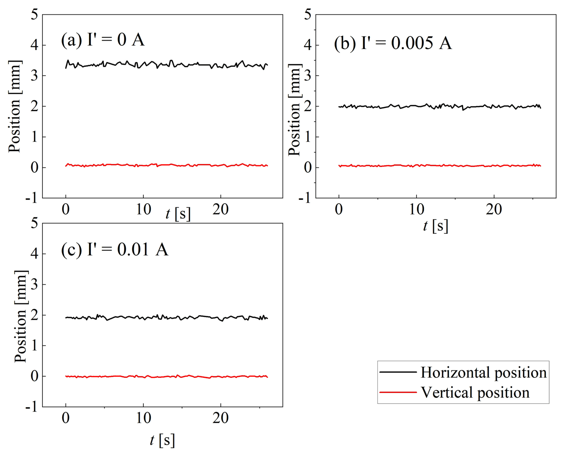
Figure 12Position changes of the magnetic ball suspended at the center of a pipe under various conditions, with a flow velocity of 0.24 m s−1. (a) . (b) A. (c) A.
Under single-electromagnet drive, the horizontal fluctuations of the magnetic ball range from 0.25 to 0.35 mm, while the vertical fluctuations range from 0.1 to 0.2 mm. With dual-electromagnet drive, the horizontal fluctuations are reduced to below 0.21 mm, with a minimum value of 0.134 mm. The vertical fluctuations are reduced to below 0.11 mm, with a minimum of 0.063 mm. When the lower electromagnetic drive current is increased from 0.005 to 0.01 A in dual-electromagnet drive, the fluctuations of the magnetic-levitation ball do not exhibit a significant change. In single-electromagnet drive, the maximum fluctuation of the magnetic ball is recorded at 0.08 m s−1. In contrast, when using a dual-electromagnet drive, the maximum fluctuation of the magnetic ball occurs at 0.24 m s−1.
Magnetic balls are primarily influenced by fluid forces in the horizontal direction and electromagnetic forces in the vertical direction. The horizontal fluctuations of the magnetic-levitation ball are greater than its vertical fluctuations, indicating that the pipe flow contributes to the instability of the magnetic-levitation ball, which is related to fluid disturbances. Compared with a single-electromagnet drive, the dual-electromagnet drive method significantly reduces fluctuations in the magnetic-levitation ball, especially at high pipe flow rates. This indicates that enhancing electromagnetic forces can improve the stability of the magnetic-levitation ball and mitigate the disruptive effects of fluid dynamics.
5.3 Position adjustment of magnetic-levitation ball in a two-dimensional plane
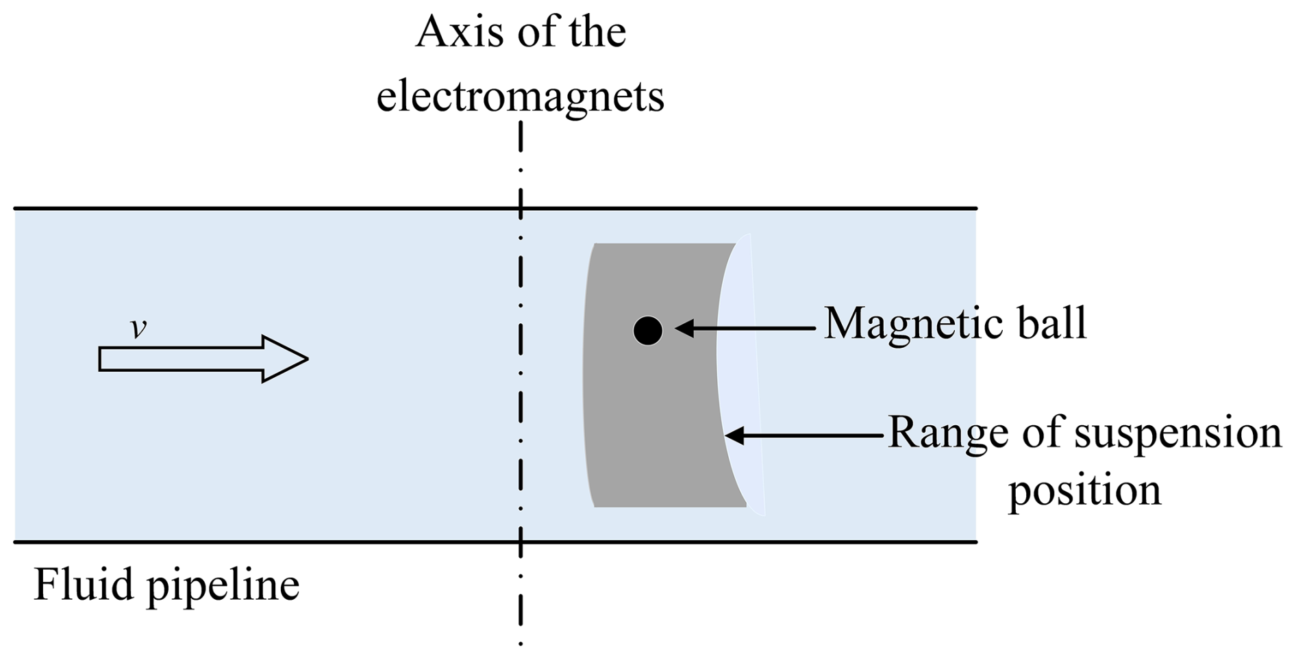
Figure 13 is a schematic diagram showing the suspension zone of the magnetic ball in the fluid pipe. As shown in Fig. 13, under the dual-electromagnet drive configuration, the magnetic ball maintains a fixed suspension position within a specific region of the fluid pipe. At a constant flow velocity, the current I in the upper electromagnet and the drive current I′ in the lower electromagnet determine the ball's precise location within the pipe. Therefore, controlling the drive currents of the upper and lower electromagnets enables accurate positioning of the magnetic ball. Figure 13 also demonstrates that, under fixed fluid conditions, when the vertical suspension position of the magnetic ball varies within the range of [−4 mm, 4 mm], its horizontal suspension position remains almost unchanged at a flow velocity of 0.08 m s−1. However, when the flow velocity increases to 0.24 m s−1, the ball exhibits a significantly larger suspension area. Thus, under high-flow conditions of 0.24 m s−1, regulating the magnetic ball's position within the planar region becomes more critical.
To precisely control the suspension position of the magnetic ball, it is essential to understand the specific relationship between the ball's position and the driving current of the electromagnet. The ball's position includes both vertical and horizontal components. Figure 14 illustrates the relationship between the vertical position of the magnetic ball suspended in a fluid flowing at 0.24 m s−1 and the driving current. The scatter points represent measured data, while the curve indicates the fitted line. As shown in Fig. 14, when the driving current of the lower electromagnet is held constant, the vertical position of the magnetic ball exhibits a negative correlation with the driving current of the upper electromagnet. The higher the position of the magnetic ball, the smaller the driving current of the upper electromagnet; conversely, the lower the position of the magnetic ball, the larger the driving current of the upper electromagnet. This occurs because a lower position of the magnetic ball means a greater distance from the upper electromagnet, requiring a higher driving current to maintain the electromagnetic force necessary for suspension.
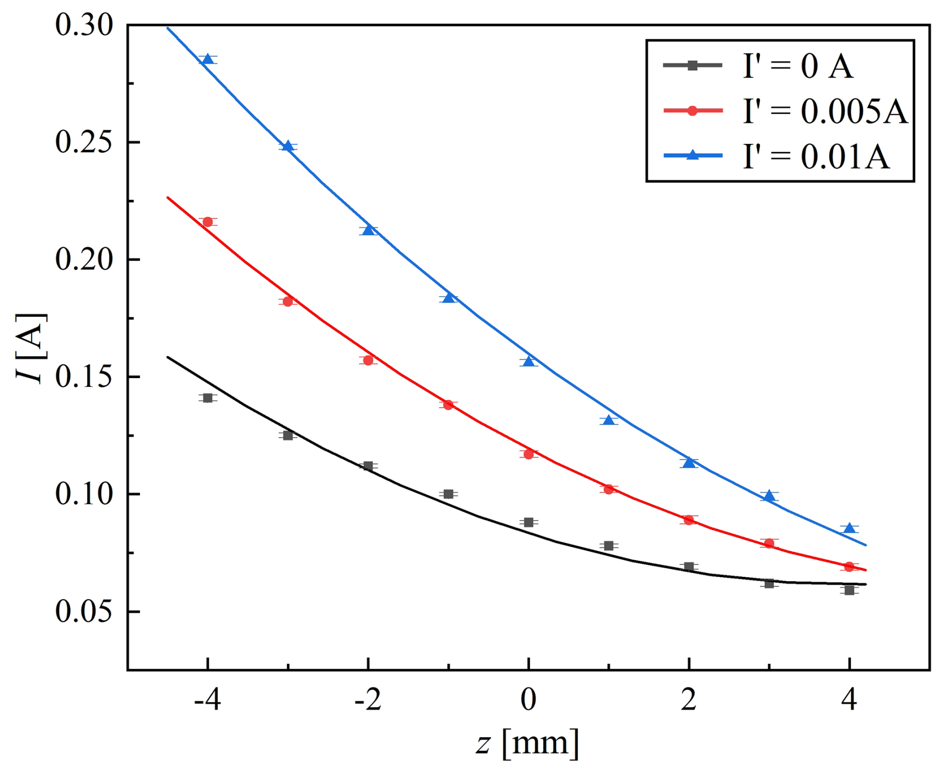
Figure 14Relationship between the vertical position of the magnetic ball suspended in a fluid pipe and the driving current of electromagnets.
When the driving current of the lower electromagnet increases, the magnetic ball rises to a higher suspension position. As shown in Fig. 14, to maintain the same vertical position, a larger driving current is required in the lower electromagnet to offset the increased current in the upper electromagnet. This is because, when the currents in both electromagnets increase synchronously, the upward electromagnetic force Fm1 and the downward electromagnetic force Fm2 acting on the magnetic ball also increase synchronously, ensuring that the forces acting on the magnetic ball in the vertical direction remain balanced. A polynomial curve shown in Fig. 14 was used to fit the relationship between the driving currents of the upper and lower electromagnets and the vertical position of the magnetic ball. Its expression is given by Eq. (8), with a goodness of fit of 0.996.
The horizontal position of the suspended magnetic ball is also influenced by the driving currents of the upper and lower electromagnets. As shown in Fig. 8 in the preceding text, when the vertical position of the magnetic ball remains constant, its horizontal position decreases significantly with an increase in the driving current of the lower electromagnet. Therefore, the horizontal position of the magnetic ball can be expressed as a function of its vertical position and the current of the lower electromagnet. Figure 15 illustrates the relationship between the horizontal position and driving current when the magnetic ball is suspended in a fluid flowing at 0.24 m s−1. The scatter points represent measured data, while the curve indicates the fitted line. As demonstrated in Fig. 15, when the driving current of the lower electromagnet remains constant, the horizontal position of the suspended magnetic ball first decreases and then increases as its vertical position rises from low to high, reaching a minimum value at a certain point during this process. This phenomenon is associated with fluid resistance. Increasing the driving current of the lower electromagnet results in a substantial reduction of the horizontal position of the magnetic ball. The greater the current, the smaller the horizontal position at which the magnetic ball remains suspended. This indicates that the electromagnetic force provided by the lower electromagnet pulls the magnetic ball toward the central axis of the electromagnet (y=0).
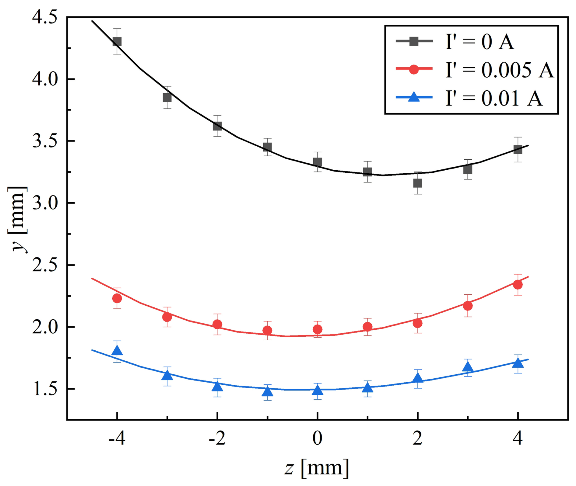
Figure 15Relationship between the horizontal position, vertical position, and the driving current of electromagnets when the magnetic ball suspended in a fluid pipe.
The scatter points in Fig. 15 were fitted with a polynomial curve, the expression of which is given by Eq. (9), with a goodness of fit of 0.997.
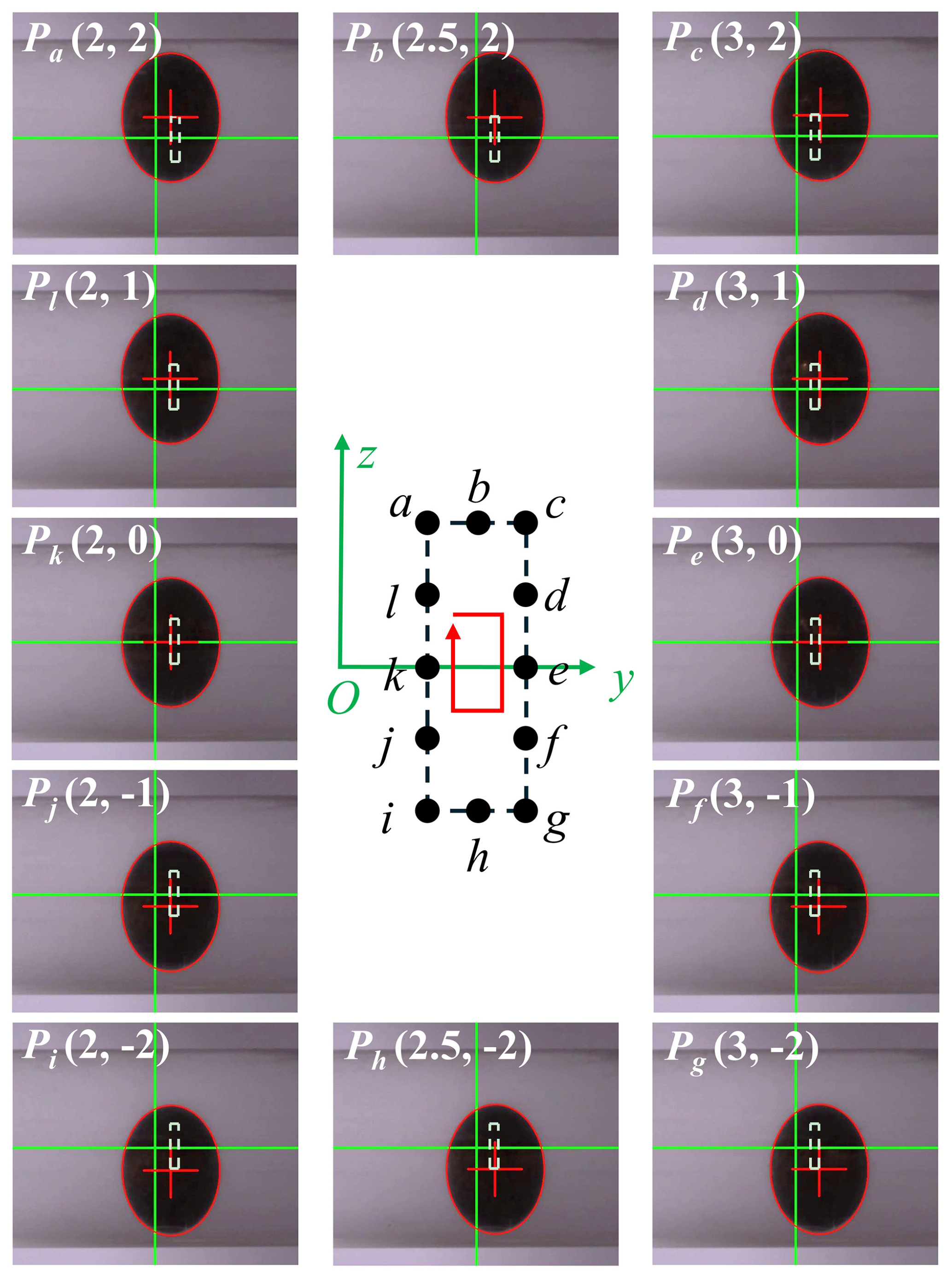
Equations (8) and (9) establish the relationship between the suspension position of the magnetic ball and the driving currents of the electromagnets. It is possible to calculate the required driving currents for the upper and lower electromagnets to achieve a target position of the magnetic ball. The regulation of these currents enables precise control of the magnetic ball's suspension position within the area delineated in Fig. 13. The test points (a, b, c, d, …, l) are defined in Fig. 16. These points form a regular rectangle, with a horizontal position range of [2 mm, 3 mm] at 0.5 mm intervals and a vertical position range of [−2 mm, 2 mm] at 1 mm intervals. By calculating and adjusting the currents of the two electromagnets, the magnetic ball was suspended at different positions along these rectangular paths. Figure 16 also shows photographs of the magnetic ball suspended at various positions along the rectangular path. The dashed white lines in Fig. 16 indicate the defined rectangular trajectories. Due to cylindrical distortion in the vertical direction of the photographs, the vertical lengths and distances appear to be significantly larger than the horizontal dimensions. The magnetic ball maintains precise suspension at each specified location. Compared with single-electromagnet drive, the dual-electromagnet drive enables two-dimensional positional control of the ball within a plane. In contrast, a single-electromagnet drive only allows positional adjustment along specific paths (corresponding to in Fig. 8).
Based on the fixed-point suspension of the magnetic ball, continuous position switching at multiple suspension points enables stepwise motion of the ball within the pipe flow. Points a, b, c, d, …, l in Fig. 16 are used sequentially as switching points for the magnetic ball's stepwise movement. The ball traces clockwise motion along a rectangular path at various velocities. The time interval between successive steps, represented as Δt, is assigned values of 2, 1, 0.5, and 0.2 s. Figure 17 illustrates the horizontal and vertical position tracking of the magnetic ball during motion. For further information, please refer to Videos S1–S4 in the Supplement. Figure 17a shows a comparison of the position tracking of the magnetic ball at intervals of 2 and 1 s. It shows that the ball's position initially overshoots during switching before reaching a steady state. During the stepping motion, the maximum horizontal overshoot reached 0.463 mm, while the vertical overshoot peaked at 0.289 mm. The horizontal overshoot was found to be significantly greater than the vertical overshoot. During position switching, the magnetic ball attains steady state faster in the vertical direction compared with the horizontal direction, exhibiting smaller fluctuations at steady state. Figure 17a illustrates that, once the magnetic ball attains a steady state, positional fluctuations are minimal at the central region of the pipe, whereas they are comparatively more pronounced near the bottom. This phenomenon is likely to be attributable to the localized characteristics of fluid disturbances and the nonlinear properties of the electromagnetic forces. The magnetic ball displays essentially consistent positional behavior across both intervals of 2 and 1 s, with the exception of an increase in velocity. Additionally, through calculation and control, the magnetic ball can also complete motion along other types of trajectories. For further information, please refer to Video S6 in the Supplement.
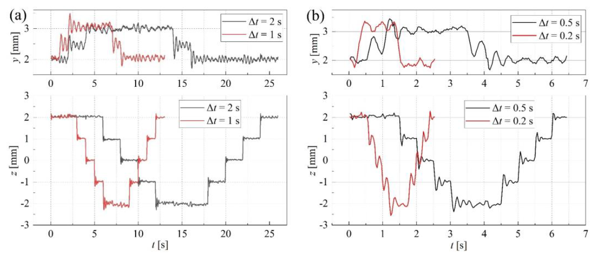
Figure 17Changes in the horizontal and vertical positions of a magnetic ball during stepwise motion along a rectangular path within a fluid pipe. (a) Comparison at Δt=2 s and Δt=1 s. (b) Comparison at Δt=0.5 s and Δt=0.2 s.
As illustrated in Fig. 17b, when the interval time is decreased to 0.5 s, the magnetic ball generally does not attain a fully steady state before the position switch occurs. This results in more pronounced fluctuations at the target position and an increase in overshoot. Further reduction in the interval time to 0.2 s exacerbates these fluctuations, causing the magnetic ball to deviate from the intended trajectory and preventing it from maintaining stability at each target position. Consequently, during low-speed stepwise motion, the magnetic ball's trajectory more closely follows the planned path, achieving an average speed of approximately 1 mm s−1. Although the magnetic ball's position becomes less stable at higher stepwise speeds, this is accompanied by a substantial reduction in operation time, with average speeds reaching up to 5 mm s−1.
Figure 18 illustrates the position error of the magnetic ball when suspended at various points labeled a, b, c, d, …, l. This error represents the difference between the mean position and the target position of the ball during steady suspension in the fluid. Both horizontal and vertical positional errors remain within 0.1 mm, demonstrating that precise positional control of the magnetic ball within the fluid pipeline is achievable. The positional error is relatively larger when the magnetic ball is located at Pi. This increase is probably caused by the nonlinearity of the electromagnet's current regulation and errors in the fitting model.
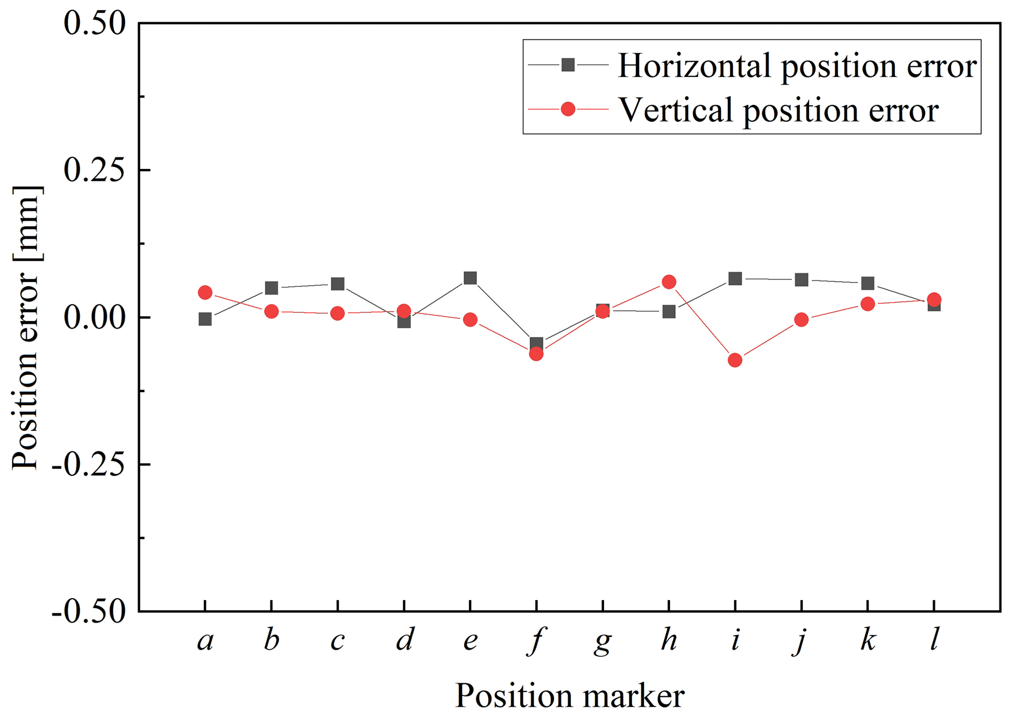
Figure 18Position errors of magnetic balls at specified locations (a, b, c, d, …, l) within a fluid pipe..
The experimental results reveal the variation in the suspension position of the magnetic ball within a fluid pipe. These results demonstrate that the vertically arranged dual-electromagnet drive configuration improves the ball's suspension performance. This finding supports research into magnetic drive methods for robots within fluid pipelines.
The magnetic ball can be suspended and moved in two dimensions in a controlled manner. Under favorable conditions, employing a dual-electromagnet drive structure can enhance the constraint force on magnetic robots, improve suspension stability, and expand the range of positional control. By leveraging the positional variation patterns of magnetically levitated balls within fluids, it is possible to perform intelligent localized position control or fine-tuning, as well as to achieve motion along desired trajectories at different velocities. These results demonstrate the feasibility of remotely manipulating robots within fluid pipelines driven by a magnetic field, thereby advancing the industrial application prospects for future miniature-pipeline robots.
Maglev drive is inherently suited to contactless, environmentally friendly, and high-precision control. Due to limitations in experimental conditions and equipment, this study has only conducted basic research under ideal conditions; further investigation is required for complex application scenarios. For instance, industrial pipelines, medical tubing, and biological lumens often feature bends, diameter variations, and branches. To adapt to these diverse pipeline environments, robots could adopt a fish-like configuration by incorporating telescoping structures and steering mechanisms into permanent magnets. While this approach offers greater degrees of freedom and extended control range, it also introduces significant challenges in robot integration and miniaturization. To address the mechanical modeling complexities in fluid environments, we plan to employ multiphysics finite-element simulations. Specifically, for magnetic ball motion, we will optimize the electromagnet structure, refine control strategies, and integrate multiple sensors to improve motion speed, positioning accuracy, and overall stability.
Based on the principles of magnetic-levitation technology, this paper presents the design of a magnetic-levitation ball drive system utilizing dual electromagnets. Stable suspension and motion of the magnetic ball within a straight, fluid-filled pipe are achieved. The effects of fluid velocity and electromagnet driving current on the suspension performance of the magnetically driven ball within the pipe flow are investigated. Differences between single-electromagnet and dual-electromagnet drives in terms of position control and suspension stability are compared. Furthermore, the proposed method achieves two-dimensional positional control and motion control of the magnetic ball within a localized fluid zone, demonstrating superior performance compared with single-electromagnet drive. The following conclusions can be drawn:
-
When the magnetic ball is stably suspended within the fluid pipe, a deviation in its horizontal position from the axis of the electromagnet is observed. It was found that the greater the fluid flow velocity, the larger the deviation, with a maximum deviation of 4.3 mm. Compared with a single-electromagnet drive, the dual-electromagnet drive method significantly reduces the horizontal displacement of the magnetic ball, effectively constraining its position. At the bottom of the pipe, the horizontal displacement of the magnetic suspension ball decreases by 58 %, being reduced to 1.8 mm.
-
The horizontal fluctuations of the magnetic suspension ball at the center of the pipe exceed the vertical fluctuations. The dual-electromagnet drive method significantly reduces these positional fluctuations, decreasing horizontal fluctuations to less than 0.21 mm and vertical fluctuations to less than 0.11 mm.
-
Based on the experimental results, a mathematical model was developed to describe the relationship between the drive current and the stable suspension position of the magnetic ball. This model was employed to control the position of the magnetic ball within a two-dimensional plane inside the fluid pipe. The magnetic ball moved along a specified trajectory in a stepwise manner, maintaining a position error within 0.1 mm.
The code and data of this paper are available on request. Please contact the corresponding author.
The supplement related to this article is available online at https://doi.org/10.5194/ms-17-825-2026-supplement.
Zhanxiang Cui proposed the method, performed the experiments, and wrote the first draft. Yun Zhu processed the data and made the figures and tables. Yonghua Lu reviewed and edited the paper.
The contact author has declared that none of the authors has any competing interests.
Publisher's note: Copernicus Publications remains neutral with regard to jurisdictional claims made in the text, published maps, institutional affiliations, or any other geographical representation in this paper. The authors bear the ultimate responsibility for providing appropriate place names. Views expressed in the text are those of the authors and do not necessarily reflect the views of the publisher.
This research has been supported by the National Natural Science Foundation of China (grant no. 51975293) and the “Taihu Light” Science and Technology Project (grant no. G20252009).
This paper was edited by Pengyuan Zhao and reviewed by two anonymous referees.
Ali, F., Imtiaz, A., Khan, I., and Sheikh, N. A.: Magnetic field effect on blood flow of Casson fluid in axisymmetric cylindrical tube: A fractional model, J. Magn. Magn. Mater., 423, 327–336, https://doi.org/10.1016/j.jmmm.2016.09.025, 2017.
Belharet, K., Folio, D., and Ferreira, A.: Control of a magnetic microrobot navigating in microfluidic arterial bifurcations through pulsatile and viscous flow, Proc. IEEE/RSJ Int. Conf. Intell. Robots Syst., 2559–2564, https://doi.org/10.1109/IROS.2012.6386030, 2012.
Bian, Z., Zhang, J., Zeng, Q., Zhang, Y., Hong, Z., and Li, S.: Design and in-orbit implement of high-precision non-contact micro-magnetic levitation control system, Space Sci. Technol., https://doi.org/10.34133/space.0645, 2026.
Cai, Z., Fu, Q., Zhang, S., Guo, S., Guo, J., Zhang, X., and Fan, C.: Characteristic analysis of a magnetically actuated capsule microrobot in medical applications, IEEE Trans. Instrum. Meas., 71, 1–11, https://doi.org/10.1109/TIM.2021.3130299, 2022.
Cui, Z., Lu, Y., Zhu, Y., Wang, Z., and Wang, Z.: A numerical simulation and an experimental study on the steady-state levitation characteristics of a magnetic ball driven by external electromagnets in a fluid tube, Strojniški Vestnik, J. Mech. Eng., 71, 103–113, https://doi.org/10.5545/sv-jme.2024.1080, 2025.
Elankavi, R. S., Dinakaran, D., Chetty, R. M. K., Ramya, M. M., and Samuel, D. G. H.: A review on various types of in-pipe inspection robot, Mater. Today: Proc., 56, 318–326, https://doi.org/10.1016/j.matpr.2022.01.087, 2022.
Elnaggar, A., Kang, S., Tian, M., Han, B., and Keshavarz, M.: State of the art in actuation of micro/nanorobots for biomedical applications, Small Sci., 4, 2300211, https://doi.org/10.1002/smsc.202300211, 2024.
Fallahiarezoodar, N. and Zhu, Z. H.: Review of autonomous space robotic manipulators for on-orbit servicing and active debris removal, Space Sci. Technol., 5, 0291, https://doi.org/10.34133/space.0291, 2025.
Hale, M. F., Sidhu, R., and McAlindon, M. E.: Capsule endoscopy: Current practice and future directions, World J. Gastroenterol., 20, 7752–7759, https://doi.org/10.3748/wjg.v20.i24.7752, 2014.
Jang, H., Kim, T. Y., Lee, Y. C., Kim, Y. S., Kim, J., Lee, H. Y., and Choi, H. R.: A review: technological trends and development direction of pipeline robot systems, J. Intell. Robot. Syst., 105, 59, https://doi.org/10.1007/s10846-022-01669-2, 2022.
Joo, S.-H., Choi, S.-H., and Yoo, H.-J.: Magnetic levitation stage technology for semiconductor processing and hybrid bonding applications, J. Microelectron. Packag. Soc., 33, 10–22, https://doi.org/10.6117/kmeps.2026.33.1.010, 2026.
Liang, N., Guo, J., and Guo, S.: Performance evaluation of the wireless micro robot in the fluid, Proc. IEEE Int. Conf. Mechatron. Autom., 958–963, https://doi.org/10.1109/ICMA.2015.7237523, 2015.
Liu, G., Lu, Y., Xu, J., Cui, Z., and Yang, H.: Magnetic levitation actuation and motion control system with active levitation mode based on force imbalance, Appl. Sci., 13, 740, https://doi.org/10.3390/app13020740, 2023.
Liu, G., Gao, M., Sun, D., Jiang, R., and Fan, L.: Three-dimensional active magnetic levitation actuating and control system for curved pipes, Appl. Sci., 14, 10871, https://doi.org/10.3390/app142310871, 2024.
Malchikov, A. V., Yatsun, S. F., Ryapolov, P. A., and Sokolov, E. A.: Studying the controlled motion of a magnetically active object in a viscous medium, Bull. Russ. Acad. Sci.: Phys., 89, 1111–1117, https://doi.org/10.1134/S106287382571178X, 2025.
Qin, Y., Cai, Z., and Han, J.: Design and control of a magnetically-actuated anti-interference microrobot for targeted therapeutic delivery, IEEE Robot. Autom. Lett., 8, 5672–5679, https://doi.org/10.1109/LRA.2023.3295648, 2023.
Qu, C., Pei, Y. C., Xin, Q. Y., Li, Z. X., and Xu, L.: A reciprocating permanent magnetic actuator for driving magnetic micro robots in fluids, Proc. Inst. Mech. Eng. Part C J. Mech. Eng. Sci., 235, 6451–6462, https://doi.org/10.1177/09544062211014547, 2021.
Ramarao, M., Garcia-Gradilla, V., Unlu, M. B., Davis, R. W., and Durmus, N. G.: Dynamic and precise electromagnetic levitation of single cells, P. Natl. Acad. Sci. USA, 12, e2512246122, https://doi.org/10.1073/pnas.2512246122, 2025.
Ruan, G., Wu, L., Han, R., and Wang, B.: Design of electromagnetic docking device for micro–nanosatellite, Adv. Astronaut. Sci. Technol., 5, 341–350, https://doi.org/10.1007/s42423-022-00121-9, 2022.
Schmitt, C. K., Medina-Sánchez, M., Edmondson, R. J., and Schmidt, O. G.: Engineering microrobots for targeted cancer therapies from a medical perspective, Nat. Commun., 11, 5668, https://doi.org/10.1038/s41467-020-19322-7, 2020.
Sun, H., Liu, J., and Wang, Q.: Magnetic actuation systems and magnetic robots for gastrointestinal examination and treatment, CJEE, 3, 1–28, https://doi.org/10.23919/CJEE.2023.000009, 2023.
Tayebi, J., Chen, T., and Wang, H.: Dynamics and control of flexible satellite using reaction sphere actuators, Space Sci. Technol., 3, 0077, https://doi.org/10.34133/space.0077, 2023.
Yang, P., Han, Y., Mo, C., Luo, J., Shou, M., Gong, X., and Zhou, Z.: A review and perspective of magnetic-controlled microbots for medical applications, Chem. Eng. J., 520, 165814, https://doi.org/10.1016/j.cej.2025.165814, 2025.
Yesin, K. B., Vollmers, K., and Nelson, B. J.: Modeling and control of untethered biomicrorobots in a fluidic environment using electromagnetic fields, Int. J. Rob. Res., 25, 527–536, https://doi.org/10.1177/0278364906065389, 2006.
Yunas, J., Mulyanti, B., Hamidah, I., Mohd Said, M., Pawinanto, R. E., Wan Ali, W. A. F., Subandi, A., Hamzah, A. A., Latif, R., and Yeop Majlis, B.: Polymer-based MEMS electromagnetic actuator for biomedical application: A review, Polymers, 12, 1184, https://doi.org/10.3390/polym12051184, 2020.
Zhang, C., Lu, Y., Liu, G., and Ye, Z.: Research on one-dimensional motion control system and method of a magnetic levitation ball, Rev. Sci. Instrum., 90, 115005, https://doi.org/10.1063/1.5119767, 2019.
Zheng, T., Wang, X., Li, H., Zhao, C., Jiang, Z., Huang, Q., and Ceccarelli, M.: Design of a robot for inspecting the multishape pipeline systems, IEEE/ASME Trans. Mechatron., 27, 4608–4618, https://doi.org/10.1109/TMECH.2022.3162192, 2022.
- Abstract
- Introduction
- Dual-electromagnet magnetic drive system
- System modeling
- Experimental methods
- Point suspension of magnetic ball in a fluid pipe
- Discussion
- Conclusion
- Code and data availability
- Author contributions
- Competing interests
- Disclaimer
- Financial support
- Review statement
- References
- Supplement
- Abstract
- Introduction
- Dual-electromagnet magnetic drive system
- System modeling
- Experimental methods
- Point suspension of magnetic ball in a fluid pipe
- Discussion
- Conclusion
- Code and data availability
- Author contributions
- Competing interests
- Disclaimer
- Financial support
- Review statement
- References
- Supplement