the Creative Commons Attribution 4.0 License.
the Creative Commons Attribution 4.0 License.
 | 27 May 2026
Adaptive compliant milling control for switch rail edge deburring within an FDAFC-based robotic framework
Kang Xu
Quang Li
Jianyong Li
Wengang Fan
Zhiwei Wu
Jiameng Liu
The burrs remaining on switch rails are prone to cracking or even fracturing during operation, thereby diminishing their service life. Moreover, the complex profile of the switch rail makes stable robotic milling difficult, with constantly changing posture and milling force. Therefore, this paper proposes a feed–displacement dual-channel adaptive force control (FDAFC) framework comprising a tangential force–speed loop and a normal-force–displacement loop. The tangential loop employs feed-per-tooth normalization combined with an engagement-aware force–speed mapping and first-order gain scheduling. This design adaptively corrects the feed to regulate tangential force and compensate for engagement-dependent nonlinearities, thereby reducing cross-coupling with the normal channel. The normal loop uses position-based impedance control with radial basis function (RBF)-scheduled inertia, damping, and stiffness to track the desired normal force under time-varying loads. A Lyapunov-guided adaptation law guarantees uniform boundedness, asymptotic tracking-error convergence, and closed-loop stability. Finally, integrated co-simulation and experiments substantiate the efficacy of the compliant milling force-tracking controller for switch rail deburring. The long-distance milling method for robots proposed in this study offers a new approach for automatic burr removal from the switch rail.
- Article
(8515 KB) - Full-text XML
- BibTeX
- EndNote


Railway turnout is responsible for changing train tracks and plays a crucial role in railway operations. The switch rail is a core structural component of the switch, which operates under complex loading conditions for extended periods. Its manufacturing quality directly impacts the safety of railway operations (Wang and Lei, 2021; Wang et al., 2025a). Problems such as hard burrs and residual milling chips appear in computerized numerical control (CNC) milling of switch rails, which leads to cracks in the service process, shortens their service life, and affects the safety of railway transportation (Jin et al., 2020; Wang et al., 2023). Currently, burr removal from the switch rail is primarily performed manually, which results in issues such as low quality, poor consistency, and incomplete grinding (Xiao et al., 2023; Ge et al., 2025). Therefore, the development of an automated burr removal method for switch rails is crucial.
During automated deburring, unstable boundary recognition and geometric mismatch can hinder the setup of reliable geometric references for tool path planning and control. Existing studies mainly focus on burr detection, CAD-to-point-cloud registration, and geometry-aware tool path correction. Mohammed et al. (2023) proposed a sparse convolutional neural network (CNN)-based pipeline for 3D burr detection and height estimation and enhanced geometric alignment robustness via robust registration. Villagrossi et al. (2017) and Lai et al. (2018) integrated laser- or vision-based measurement with robot motion to enable online acquisition of geometric information and real-time trajectory correction. González et al. (2024), in contrast, leveraged an industrial camera and contour-deviation processing to enable fast edge identification and generated NC subprograms in stages to accommodate part deformation and variations in burr scale. However, these methods mainly enhance the geometry-to-tool path stage, while contact machining still demands explicit force control and adaptive compensation to handle milling load disturbances, pose-dependent contact conditions, and overcut sensitivity of the thin edge.
Once the geometric reference is established, the kinematic smoothness of the generated trajectory directly influences the process' dynamic stability. Rahul and Chiddarwar (2024) used deep reinforcement learning for model-free path planning and converted the planned paths into executable trajectories using inverse-Jacobian mapping. Zhang et al. (2024) improved the trade-off between efficiency and stability by incorporating adaptive weights into trajectory optimization. Tafuro et al. (2025) proposed a self-supervised vision-proprioception framework that directly maps visual inputs to deburring trajectories while mitigating sim-to-real degradation. However, these studies mainly address executability at the planning and kinematic levels. Because contact machining is highly nonlinear and subject to time-varying loads, trajectory smoothing alone is insufficient to maintain a stable contact force and consistent surface quality. Hence, trajectory planning must be integrated with contact-control strategies.
Deburring quality depends critically on end-effector contact force and equivalent compliance; therefore, hybrid position/force and impedance/admittance control are widely used to explicitly regulate the contact interaction. Classical hybrid position/force control (Raibert and Craig, 1981) achieves force–position coordination by decomposing the task space into free and constrained directions. Impedance/admittance control (Hogan, 1984) further shapes the contact response by specifying the desired interaction dynamics. In deburring applications, several task-specific improvements have been reported. Burghardt et al. (2017) combined force control with process-window optimization to achieve controlled chamfer formation. Tao et al. (2015, 2016) introduced adaptive control strategies, such as fuzzy PID and radial basis function neural network (RBFNN), to improve tracking performance and disturbance rejection. More recently, Lloyd et al. (2024) proposed the simultaneous registration and machining (SRAM-D) framework, which unifies online registration, adaptive admittance tuning, and feed-rate regulation in a closed-loop architecture to jointly handle geometric uncertainty and contact stability. Existing validations are predominantly conducted on small to medium workpieces under fixed-base or short-stroke conditions. Under long-distance continuous machining, common assumptions, including a limited workspace, nearly constant compliance, and locally compensable errors, may no longer be valid.
Currently, burr removal strategies for robot milling, both domestically and internationally, primarily focus on medium and small workpieces (Burghardt et al., 2017; Villagrossi et al., 2017; Tao et al., 2016; Zhang et al., 2024). Due to the switch rail length, which can exceed 40 m, long-distance robot motion leads to increased errors and degraded system stability compared with stationary operation. The switch rail profile is complex and variable, with the switch rail edge's cross-section gradually changing along its length (Tang et al., 2026; Grossoni et al., 2021). Additionally, the switch rail edge is weak, and the included angle increases progressively (Kisilowski and Kowalik, 2020). Consequently, both the milling angle and the force change. However, during machining, the robot must both prevent force-induced overcut of the thin edge and maintain stable regulation under force variations. This requires adaptive adjustment according to edge characteristics and milling load changes to achieve compliant and stable contact with the switch rail edge (Chen et al., 2024; Wang et al., 2025b). To address the varying cross-sectional geometry of the switch rail edge and the challenges of long-distance robotic feed milling, this paper proposes a linear-motor–robot machining system. Building on hybrid position/force and impedance-control principles, a structured dual-loop adaptive force controller is developed for variable expected force milling. The main contributions of this paper are as follows:
-
Tangential force–speed control is implemented via feed-per-tooth normalization with adaptive feed correction and first-order gain scheduling while also decoupling the normal-force–displacement loop.
-
Position-based impedance with RBF parameter adaptation realizes normal-force–displacement control, and Lyapunov-based design guarantees bounded tracking/asymptotic convergence under nonlinear time-varying milling disturbances.
-
The effectiveness and stability of the smooth control strategy proposed in this paper are validated through Simulink and ADAMS co-simulation and experimental verification.
The structure of the paper is organized as follows. Section 2 introduces the robot milling system. Section 3 presents the robot's kinematics and dynamics. Section 4 establishes the adaptive milling force control strategy. Section 5 presents a co-simulation with Simulink and ADAMS. Section 6 concludes with experimental verification. Finally, the conclusion is given in Sect. 7.
The robot is mounted on a linear-motor module to satisfy the long-distance milling requirements of the switch rail, forming a 7-DOF linear-motor–robot system. The robotic machining system mainly consists of linear-motor modules, an industrial robot, and an end-effector, as shown in Fig. 1. The linear-motor module integrates the drive and guide rail functions, enabling straight-line robot motion, and its modular design accommodates switch rails of different lengths. The end-effector consists of an electrically driven spindle, a milling cutter, and a six-axis force sensor. During machining, the spindle drives the high-speed cutter for switch rail milling, while the force sensor mounted at the robot end measures the milling force in real time.
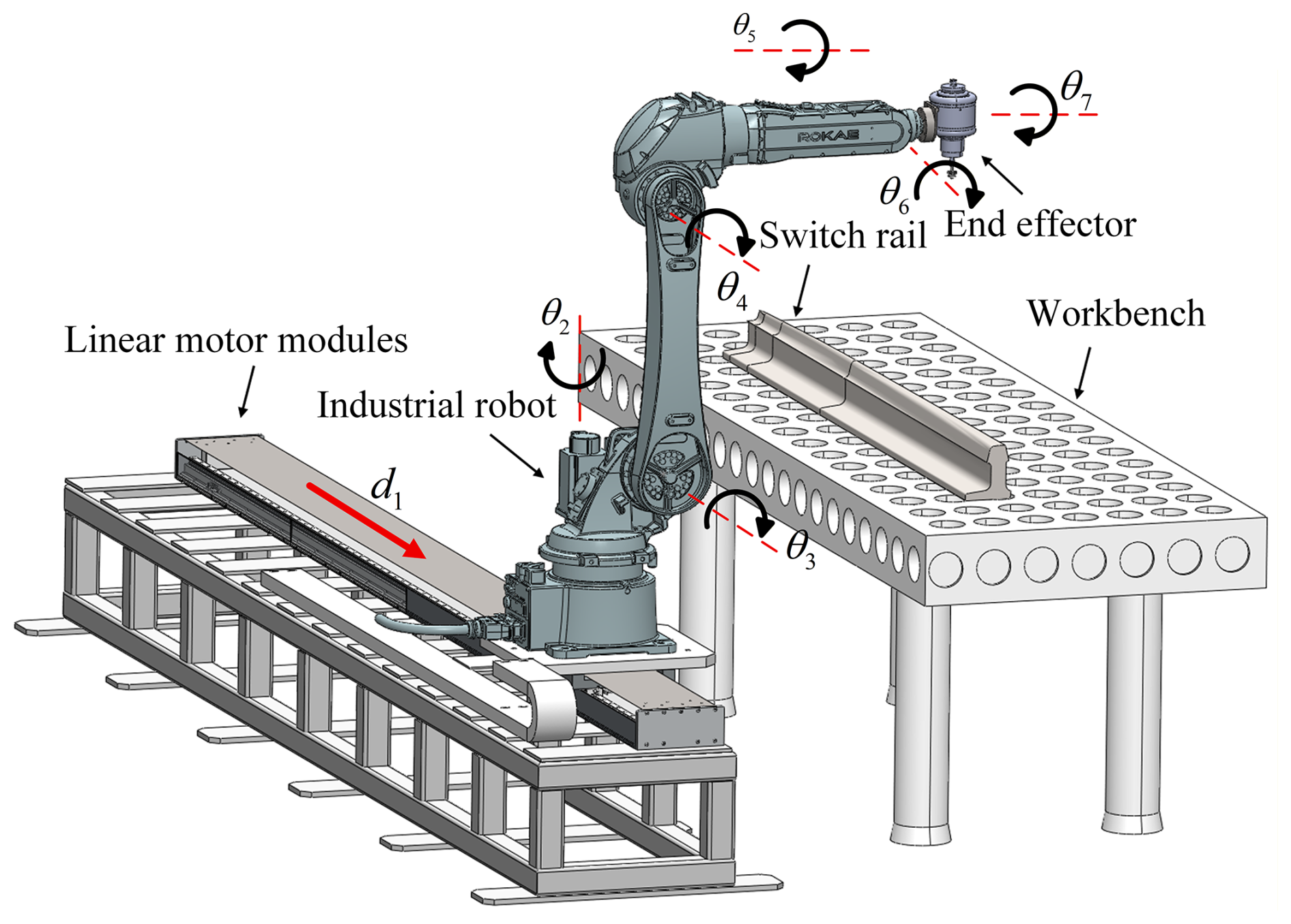
The joint kinematics of the robotic milling system are established using an improved D–H parameter method, with the joint coordinate frames shown in Fig. 1. The D–H parameters are shown in Table 1, with the first motion joint of the system being a prismatic joint (di) and the remaining six joints being revolute joints (θi).
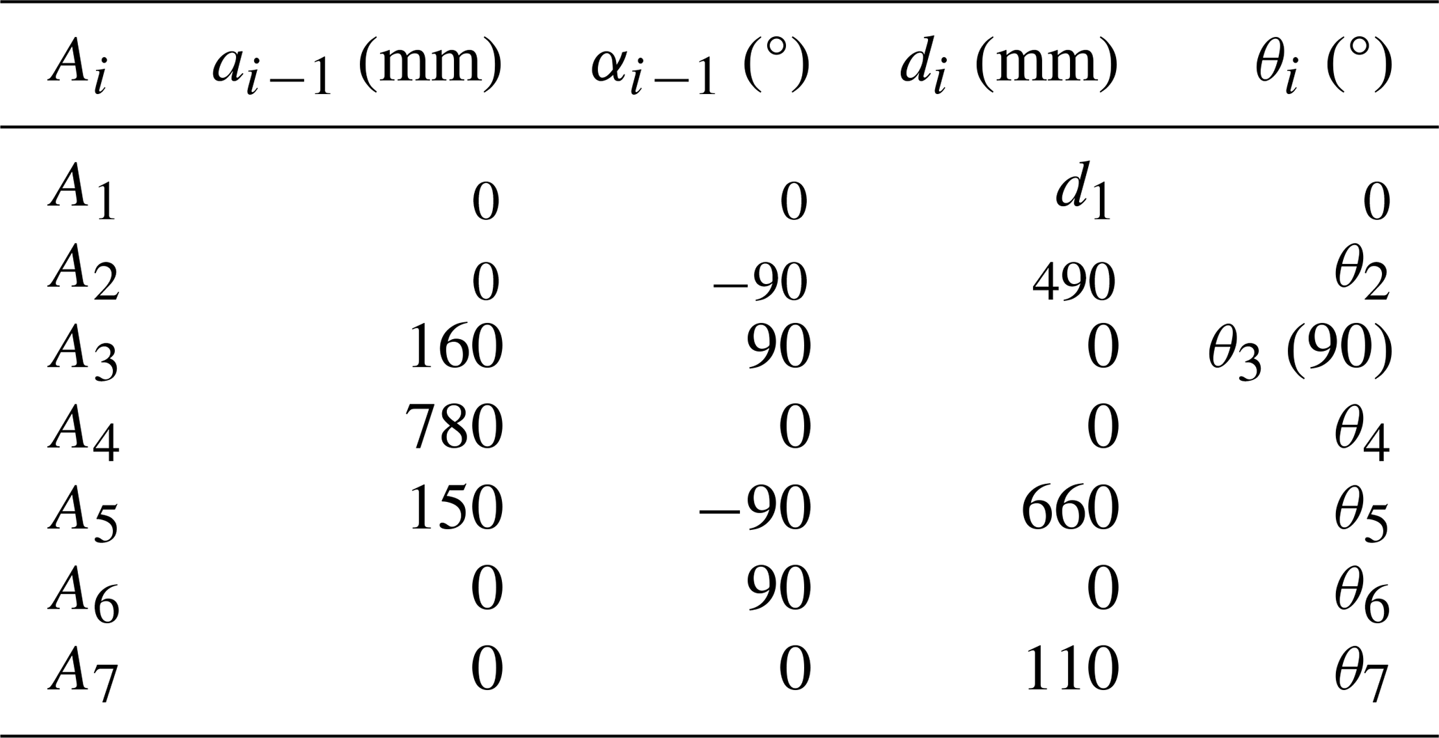
Based on the D–H parameter table, the transformation relationship of coordinate system i relative to i−1 is established, and the homogeneous transformation matrix can be expressed as
The coordinate transformation relationship of the end-effector relative to the base of the robot milling system can be obtained as
where and a values are the end-effector orientation, and p denotes the position. Once the joint angles of the robotic arm are obtained, the end-effector position and orientation can be calculated using Eq. (2).
The proposed milling system is modeled as a 7-DOF serial chain, where the linear motor is represented as the first prismatic joint d1, followed by six revolute joints θ2−θ7. Therefore, the forward kinematics, Jacobian mapping, and the subsequent dynamic recursion are all formulated based on this prismatic–revolute joint sequence.
Given the end-effector velocity vector in Cartesian space, the corresponding joint velocity is derived using the Jacobian pseudo-inverse method (Khan, 2023; Ma et al., 2025):
where J+ is the Moore–Penrose pseudo-inverse of the Jacobian matrix, . is an arbitrary joint velocity vector in the null space. This formulation can yield the minimum-norm joint velocity solution. To improve trajectory smoothness and maintain stability, an acceleration-level gradient projection with damping is introduced (Kratěna et al., 2025; Xie et al., 2022):
where T is the gain matrix, and is the damping term, which can ensure the stability of the motion. −K∇H(q) is the gradient of the performance index function. This control law suppresses abrupt joint accelerations while ensuring tracking accuracy. In null-space optimization, a weighted L2-norm minimization strategy is adopted to balance joint motion and system stability (Tiseo et al., 2024):
where is a positive definite weight matrix. Joint weights are assigned according to their motion importance under machining conditions; for example, a higher weight can be set for the frequently moving third joint to suppress excessive displacement variations.
In addition, the driving force or moment along the desired trajectory is calculated using the Newton–Euler recursion method (Zhou et al., 2025; Bai et al., 2024), incorporating the displacement, velocity, and acceleration of the robot joints. The following is for the kinetic analysis of the rotational pair. The extrapolation method for calculating velocity and acceleration () is
where denotes the angular velocity of link i+1 in frame i+1; denotes the rotation from frame i to frame i+1. is the angular velocity of joint i+1; and are the linear accelerations of the origin of frame i+1 and its center of mass, respectively; and is the unit vector along the z axis of frame i+1. iPi+1 is the origin of the position of frame i+1 in the coordinate system of joint i. is the position vector of the center of mass of link i+1 expressed in frame i+1.
Moreover, the forces and moments are calculated using an extrapolation method ():
where ifi is the interaction force acting on link i, expressed in the coordinate system of joint i; similarly, ini is the torque of action. FN values are the inertial force and inertial moment, respectively. τ is the driving torque of joint i.
The following is for the kinetic analysis of the mobile pair. The extrapolation method for calculating velocity and acceleration (i=0) is
where d is the displacement of the mobile pair. The extrapolation method for calculating forces and moments (i=1) is
Considering the effect of gravity, the initial value can incorporate the gravitational effect on the link into the dynamic recurrence equation.
4.1 System architecture of adaptive force control
The feed–displacement dual-channel adaptive force control (FDAFC) comprises a tangential force–speed loop and a normal-force–displacement loop. This separation is physically motivated by the different roles of tangential and normal contact interactions in milling. The tangential force mainly reflects feed-related engagement and cutting-load variations, whereas the normal force is governed by contact compliance and overcut avoidance under changing local stiffness and geometry. At each iteration, the controller updates the feed speed using the measured tangential force. The resulting correction modifies the feed per tooth and is propagated to the normal loop via an explicit normal-force reference update channel. When the burr distribution or tool-workpiece engagement changes, the tangential loop re-estimates the speed correction and updates the normal reference accordingly. This coupled–decoupled–recoupled operation enables stable and efficient compliant machining, as shown in Fig. 2.
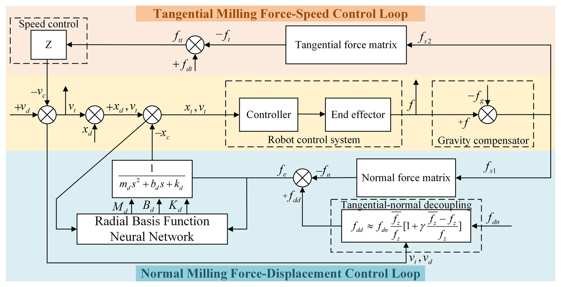
The tangential loop decouples speed regulation using feed-per-tooth normalization and an engagement-aware force–speed map. A scalar update law computes the feed speed correction from the tangential force error and drives the inner motion loop. A first-order gain-scheduled approximation around the operating point mitigates engagement-dependent nonlinearity: it reduces to the nominal linear model when the scheduling variable is zero and provides first-order compensation otherwise.
The normal loop employs position-based impedance control driven by the normal-force error. To reject time-varying milling loads and contact-parameter variations, the inertia, damping, and stiffness are adapted online using a radial basis function neural network (RBFNN). The Lyapunov-based update laws guarantee uniform boundedness and closed-loop stability. Under standard assumptions, the force-tracking error converges, ensuring stable compliant machining.
4.2 Tangential milling force–speed control
During burr milling, maintaining a fixed cutter feed speed may lead to excessive tangential force, causing cutter wear or even tool failure. Therefore, the feed speed must be adaptively adjusted according to the measured tangential milling force. The empirical relationship between initial feed speed V and cutter parameters can be expressed as
where Z′ is the number of blades, ; n is the spindle speed; and is the amount of milling feed per edge of the cutter.
For cylindrical milling, the relationship between feed speed and milling force is (Shaw and Cookson, 2005; Groover, 2010)
where ae and ap denote the side and back cutting amount, fZ" is the feed per tooth, Z" is the number of cutter teeth, d is the cutter diameter, and KF is the correction factor. Hence, the speed control model can be formulated as follows:
where Vd and V are the expected and initial feed speed, Fdt and Ft are the expected and actual tangential milling force, and z is the speed coefficient. The one-dimensional equation is expressed as , then
where vc is the feed speed correction. When ft=0, the end-effector is only the speed control. The corrected actual feed speed can be adjusted based on the burr distribution and the shape of the rail edge. Given input vt, the controller computes joint angles through inverse kinematics to control the end-effector feed speed.
Equation (11) indicates that the expected milling force varies with milling area and feed speed. Therefore, the coupling between tangential milling force–speed control and normal-milling force–displacement control is crucial and must be considered when designing milling compliance control.
When the tangential force–speed control model adjusts the feed speed, the expected force in the normal-force–displacement control model also changes. Tangential and normal milling forces are proportionally related to the total milling force, which allows for deriving the relationship between milling force and feed speed:
where fdn is the expected normal milling force at the expected feed speed, fdd is the expected normal milling force after velocity correction, fzn is the feed per tooth at the desired feed speed, fzd is the feed per tooth after speed correction, and C1C2 is the proportional coefficient.
According to Eqs. (10) and (14), vt is fed into the calculation module to establish the relationship between the expected normal milling force and the feed speed. The formula can be obtained as
where is the feed per tooth at the expected feed speed, is the feed per tooth after velocity correction, and k() is scheduled by feed. A first-order gain-scheduling approximation about fz is adopted as
Substituting the above into Eq. (15) yields
where setting γ=0 recovers the original linear mapping; for γ≠, in addition to the linear scaling , a first-order adaptive compensation for nonlinearity and large speed variations is introduced.
To ensure the validity of the first-order gain-scheduling approximation in Eq. (16), the feed-per-tooth variation around the nominal point fz is constrained such that . In our implementation, the velocity correction is bounded, i.e., , where δf is set to 0.3 (±30 %) in the experiments. Accordingly, γ is chosen to satisfy |γ|δf<1. For robustness under large or abrupt speed changes, is saturated before evaluating Eqs. (16)–(17), preventing excessive gain scheduling and maintaining stable closed-loop behavior.
4.3 Normal-milling force–displacement control
The force error is used as the input to the impedance model, where Fdd is the expected milling force and Fn is the actual normal milling force. The normal milling force, measured as the y-axis component of the six-axis force sensor, is simplified as a one-dimensional quantity. The impedance model is given by
where md, bd, and kd denote the desired inertia, damping, and stiffness, respectively, and x and xd are the actual and desired displacements. With position-based impedance control (Zong et al., 2025; Dong et al., 2024) and , Eq. (18) becomes . In the Laplace domain, . In free space, fn=0, yielding . Thus, the controller degenerates to position control in free space.
Dynamic variations in switch rail milling introduce nonlinear, time-varying load disturbances, rendering fixed impedance parameters inadequate. In edge milling, changes in rail-profile stiffness, intermittent burr engagement, and cutter–workpiece interaction produce a time-varying equivalent impedance that is difficult to capture with a fixed analytical model. Accordingly, an RBFNN is employed as a lightweight online function approximator to adapt MdCdKd from force-tracking errors (Zong et al., 2025; Li et al., 2025). Compared with heuristic gain scheduling, this strategy provides continuous low-cost approximation without prior identification of stiffness/friction profiles.
The input vector is Enet=[eKeCeM]T, and the radial basis vector is R=[r1r2…r6]T. Therefore, the Gaussian function rj can be expressed as follows (Zhao et al., 2025):
where Cj denotes the center position of the Gaussian function at the jth neuron in the hidden layer, Cj=[cj1cj2cj3]T, and bj represents the width of the Gaussian function at the jth neuron in the hidden layer, and it is a constant greater than 0.
The hidden-layer centers Cj are fixed a priori and uniformly distributed over the normalized input space, and a common width bj=b is chosen according to the average inter-center spacing. The network weights are initialized to zero and updated online using a discrete-time adaptation law with a learning rate of 0.5 and a sampling period of 1 ms. The learning rate is selected empirically to balance convergence speed and robustness to measurement noise.
After parameterization via RBFNN, the following equation can be derived:
where ϕ(ξ) denotes the hidden layer output, W=[w1w2…w6]T is the RBF weight vector, and ε(W) represents the approximation error associated with W. Specifically, Eq. (20) can be expressed as
where k denotes the discrete-time index. The optimal weight W∗ is defined as
For any nonlinear continuous function, the optimal weight W∗ always exists, and the corresponding approximation error ε(W∗) exhibits uniform boundedness. Accordingly, the impedance dynamics can be written as
where MdCdKd denote the desired inertia, damping, and stiffness, respectively. Then, the RBFNN input is defined as
Jacobian information of the robot end position control can be obtained as
The control criterion function can be represented as
The gradient descent method is used to adjust parameter MdCdKd:
where ηmηcηk is the learning rate for inertia, damping, and stiffness parameters, respectively. Suppose that the parameter KdCd is selected to satisfy the following inequality: . The weight adaptive law is then defined as follows:
where both and R are 6×1 vectors, P is a 1×6 vector, and W∗ is the optimal approximation value of the weights of the RBF neural network. In the stability analysis, the dominant uncertainties in the normal-force channel are treated as lumped nonlinear disturbances and approximated by the RBFNN, while the residual approximation error is assumed to be bounded. Under this assumption, the Lyapunov-based adaptation ensures bounded closed-loop signals and stable force tracking.
Table 2Tracking error of the force in segment A of the switch rail.
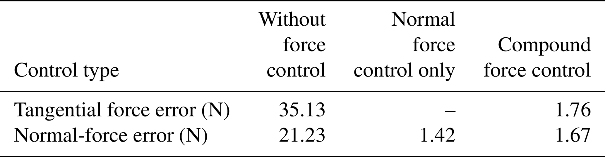
Table 3Tracking error of the force in segment B of the switch rail.
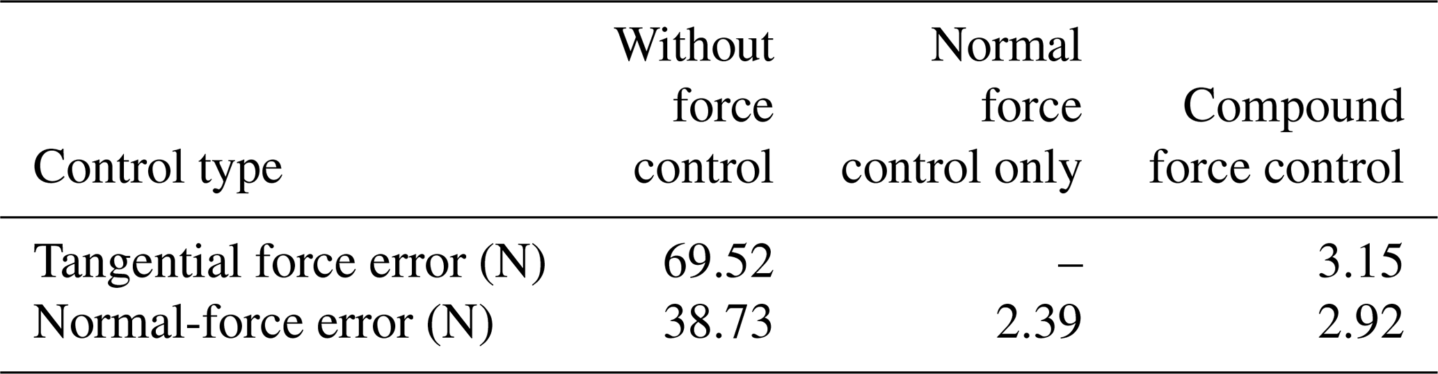
Table 4Tracking error of the force in segment C of the switch rail.
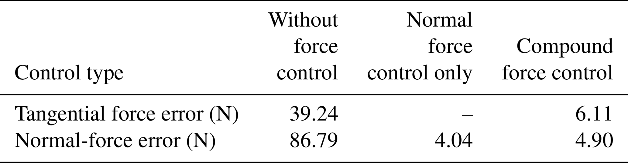
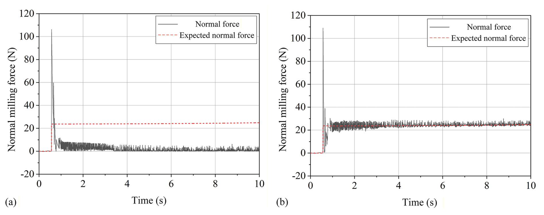
Figure 5Force response of segment A of the switch rail under normal-force control only. (a) Without force control: normal milling force. (b) Force control: normal milling force.
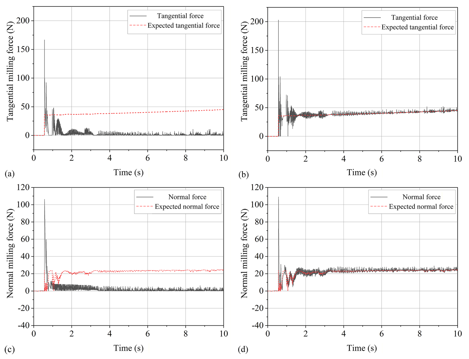
Figure 6Force response of segment A of the switch rail under compound force control. (a) Without force control: tangential milling force. (b) Force control: tangential milling force. (c) Tangential force control: expected normal milling force. (d) Force control: normal milling force.
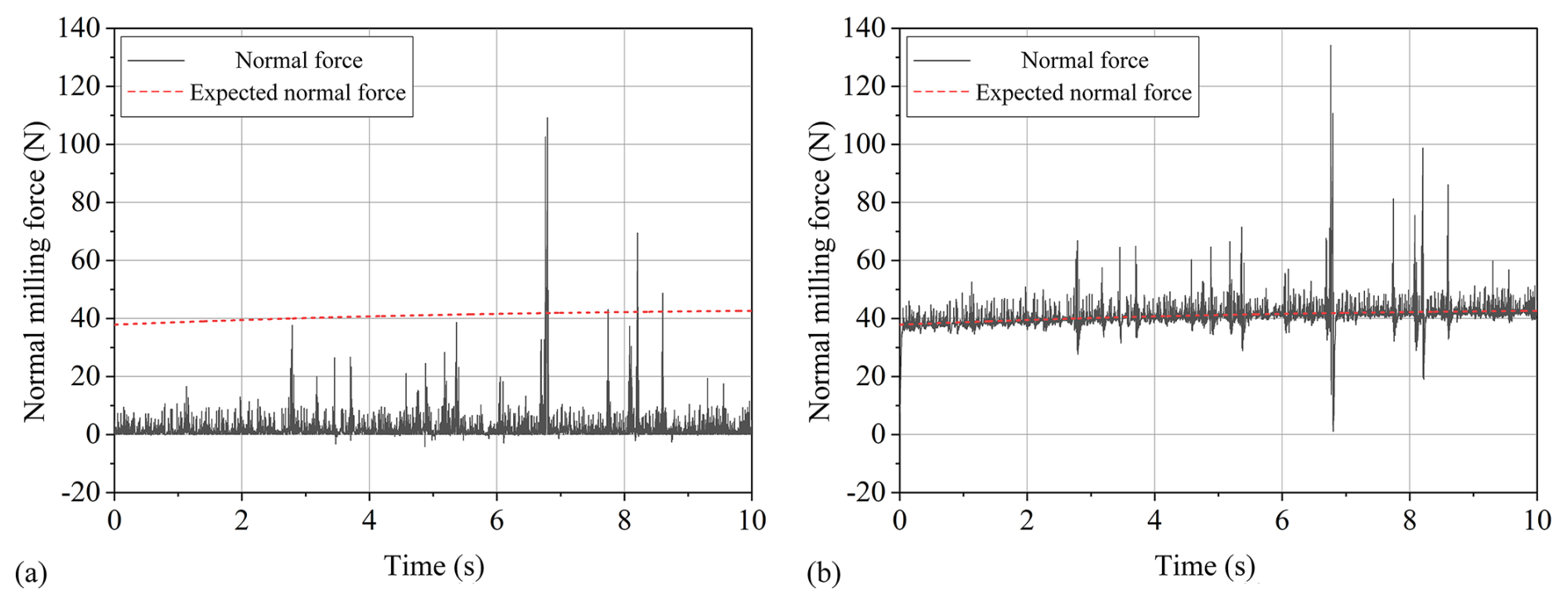
Figure 7Force response of segment B of the switch rail under normal-force control only. (a) Without force control: normal milling force. (b) Force control: normal milling force.
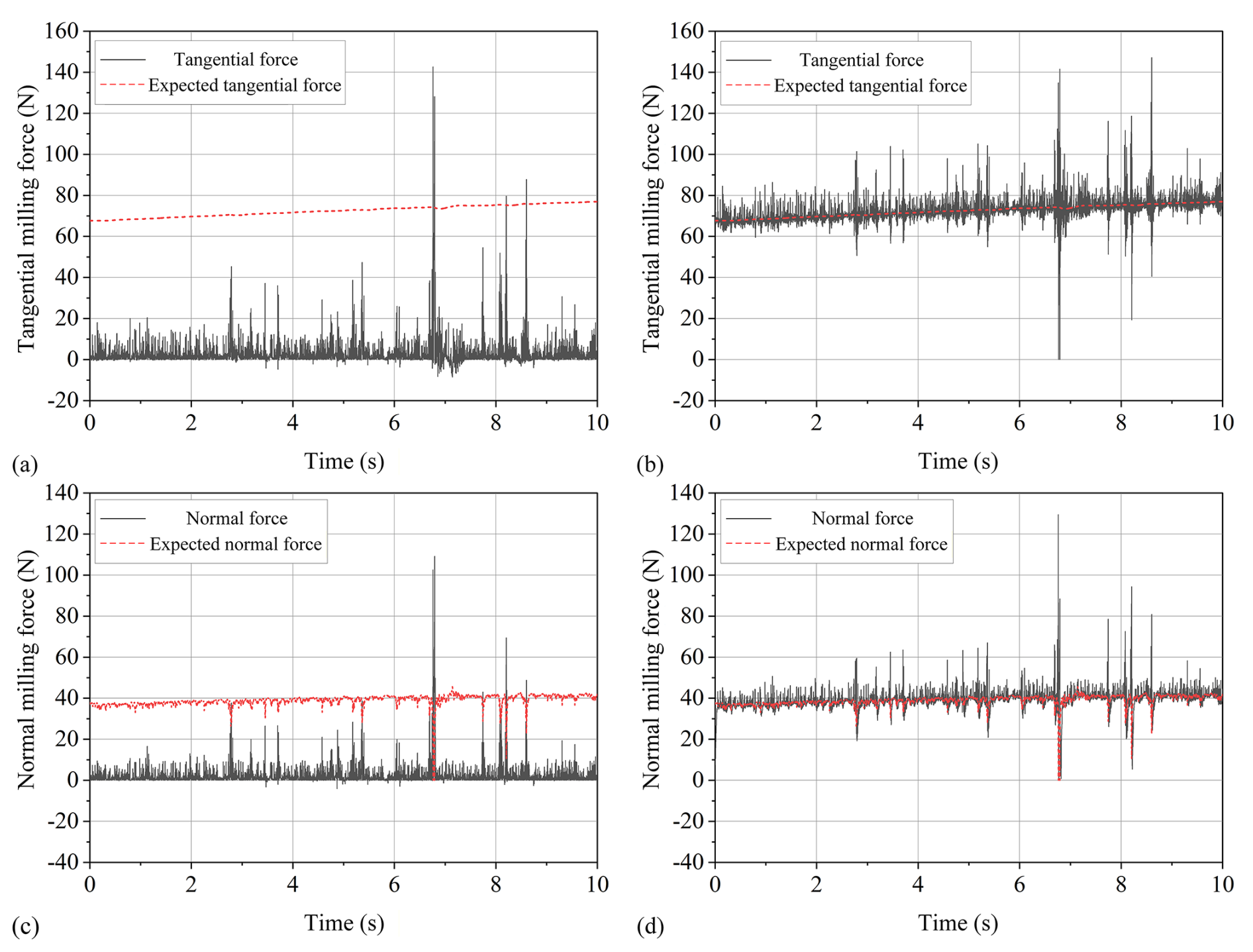
Figure 8Force response of segment B of the switch rail under compound force control. (a) Without force control: tangential milling force. (b) Force control: tangential milling force. (c) Tangential force control: expected normal milling force. (d) Force control: normal milling force.
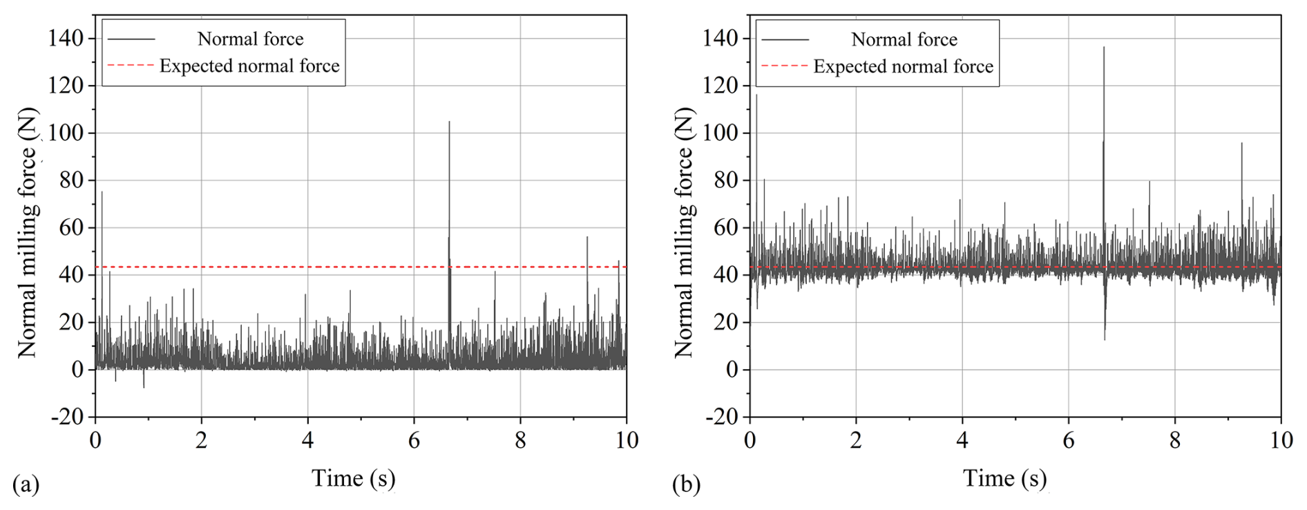
Figure 9Force response of segment C of the switch rail under normal-force control only. (a) Without force control: normal milling force. (b) Force control: normal milling force.
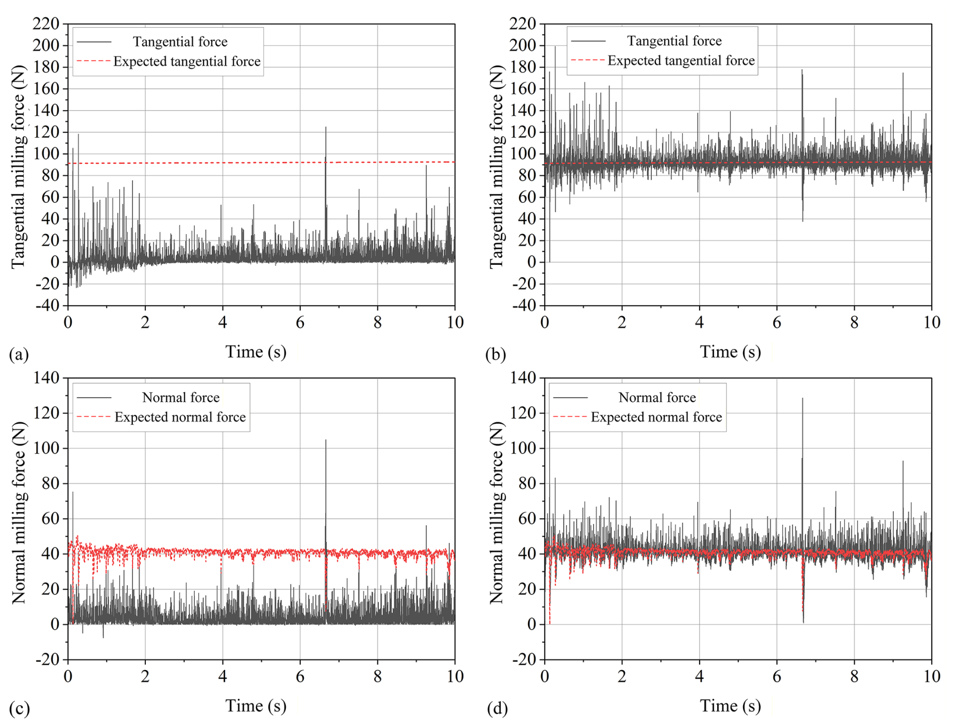
Figure 10Force response of segment C of the switch rail under compound force control. (a) Without force control: tangential milling force. (b) Force control: tangential milling force. (c) Tangential force control: expected normal milling force. (d) Force control: normal milling force.
The Lyapunov candidate (Precup et al., 2021) is defined as follows:
where . Differentiating Eq. (30) gives
Substituting Eqs. (23) and (29) into Eq. (31), the following can be obtained:
Based on the above assumptions, we can push V≥ and . When the error e=0, takes a value of 0. From the Lyapunov stability criterion, it follows that the system is asymptotically stable and the error e is uniformly bounded. Further, by invoking LaSalle's invariance principle, when k→∞, the error converges to a neighborhood of 0, thereby verifying the closed-loop stability of the control system.
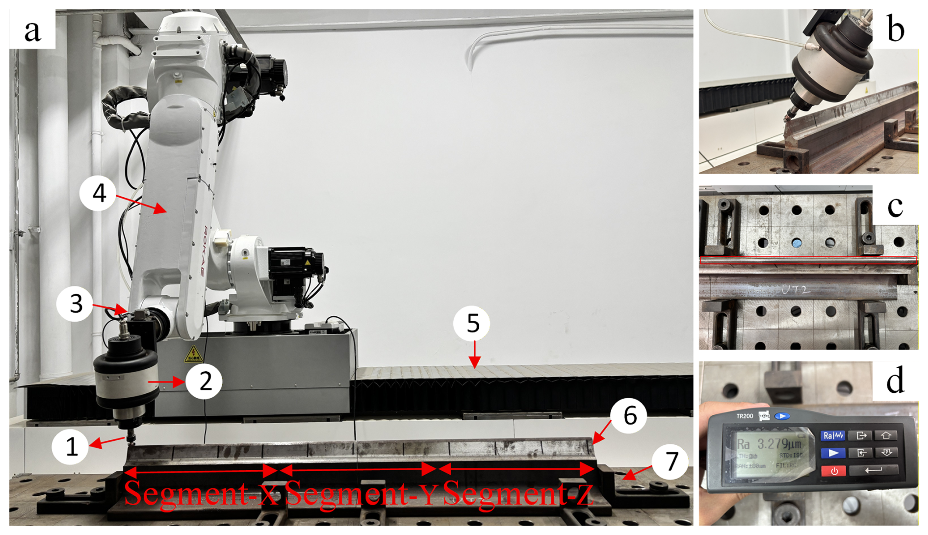
Figure 11Milling experiment on the switch rail. (a) Robotic processing system: 1. KAWAKI HANATAN 0613 cutter, 2. Electric spindle (Inlinbot RCD-E800D), 3. Six-axis force sensor (HPS-FT060S), 4. ROKAE XB25 industrial robot, 5. Linear-motor modules, 6. Chinese no. 9 switch rail, 7. Workbench. (b) Cutter–switch rail contact during milling. (c) Surface of the switch rail after milling. (d) Surface roughness after milling.
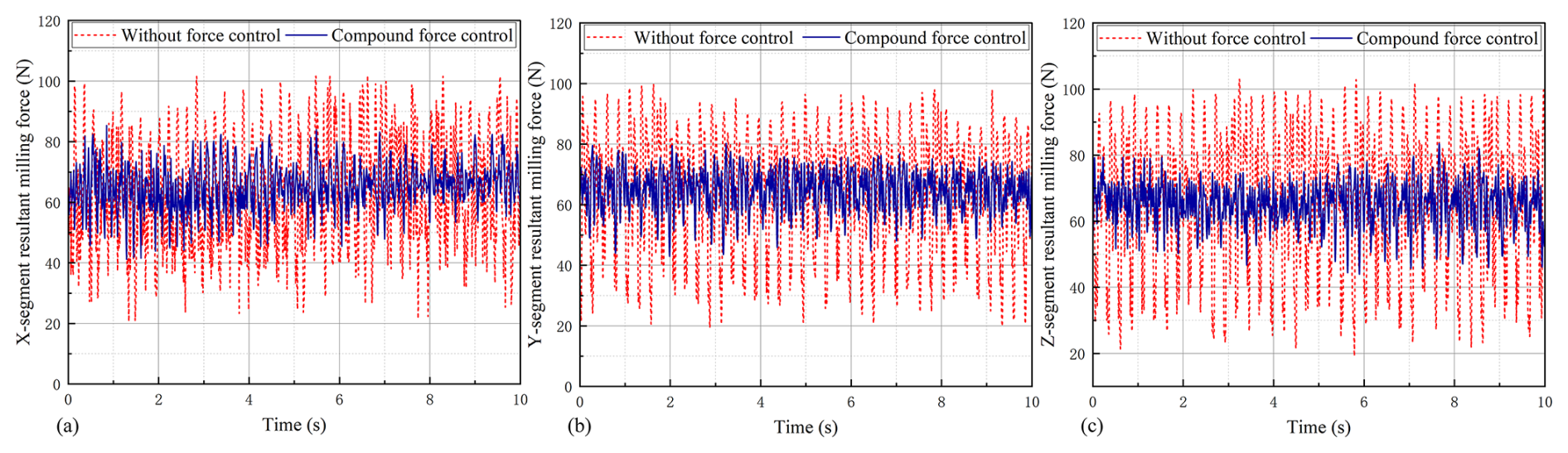
Figure 12Comparison of the resultant milling force with and without compound force control in three segments of the switch rail: (a) Segment X, (b) Segment Y, and (c) Segment Z.
5.1 Establishment of adaptive force control simulation model
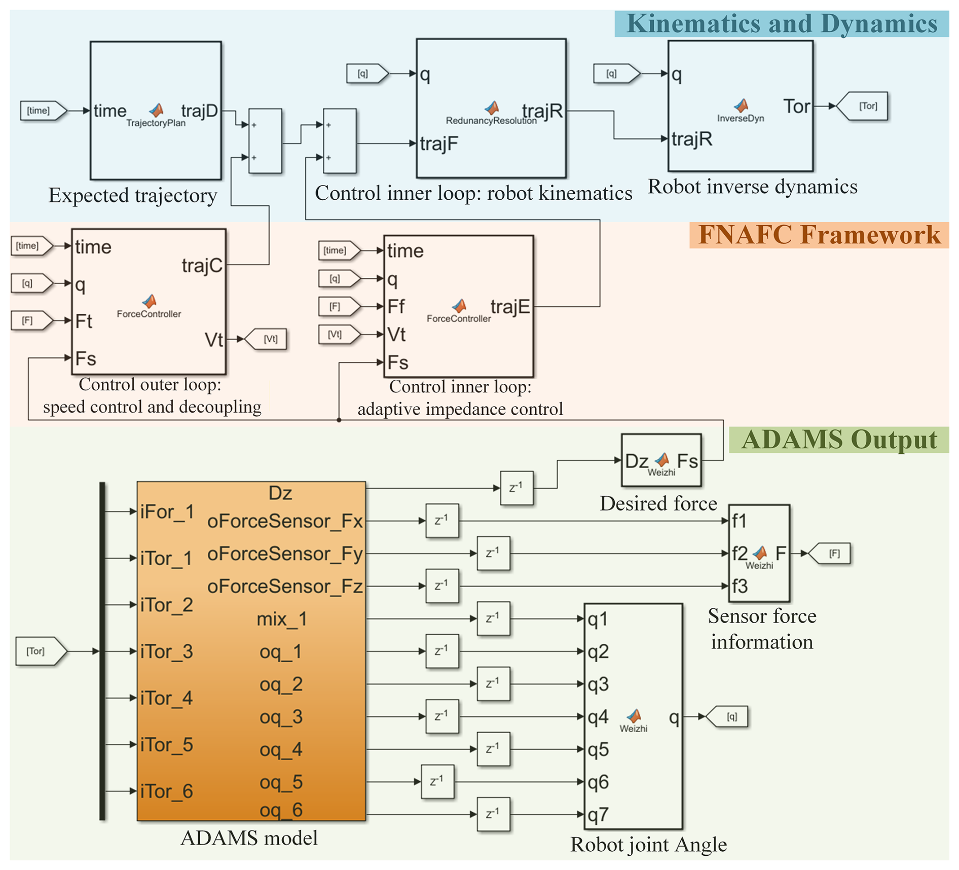
Based on the preceding analysis, the proposed controller is implemented in an ADAMS–Simulink co-simulation environment, as shown in Fig. 3. For a given reference trajectory, the outer loop regulates tangential force by adjusting the feed rate, whereas the inner loop employs adaptive impedance to regulate normal displacement and track the desired contact force. The corrected motion command is mapped to joint space via redundancy resolution. Joint torques are computed via Newton–Euler inverse dynamics and applied to the ADAMS joints as actuation inputs. The ADAMS model simulates the tool–rail contact and outputs the joint states and end-effector pose, together with the measured interaction forces and contact deflection. These signals are fed back to Simulink in real time to close the co-simulation loop and support coordinated motion–force tracking.
The linear-motor–robot system is modeled as a 7-DOF serial chain, consisting of one prismatic joint for the linear axis, followed by six revolute joints for the industrial robot, consistent with the kinematic formulation in Sect. 3. Robot links and the base are treated as rigid bodies with specified mass and inertia properties, while structural elasticities are not explicitly modeled because the co-simulation targets closed-loop control validation rather than structural vibration effects.
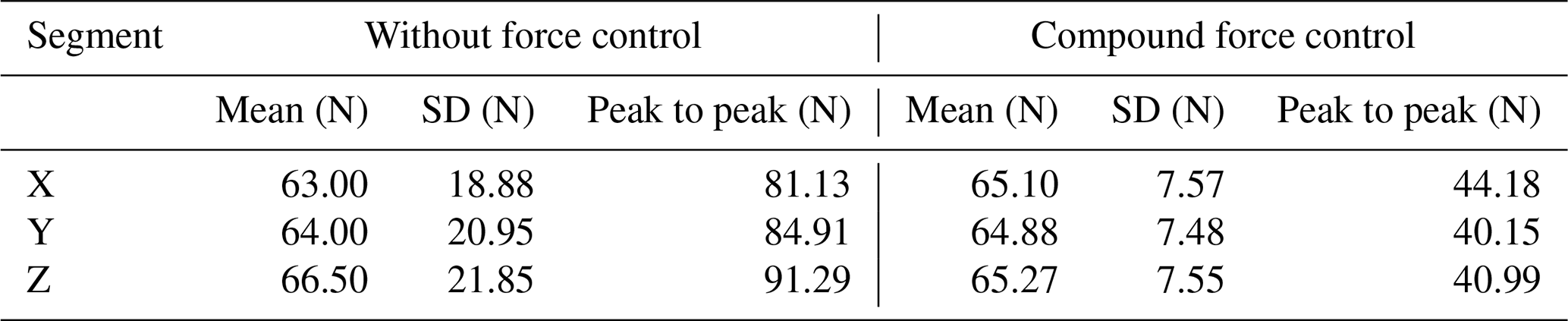
Table 5Statistics of the resultant milling force in three representative segments.
5.2 Simulation analysis of adaptive milling force control
In the ADAMS model, the milling process is represented by a tool–rail interaction model to evaluate the force-tracking performance of the proposed compliant control under specified milling conditions. The cutter and the switch rail are treated as rigid bodies. Their interaction is described by a penalty-based contact formulation that generates the normal contact force, while tangential interaction is modeled by a friction law to produce the tangential contact force. The resulting normal and tangential forces are used as the measured milling forces in the co-simulation.
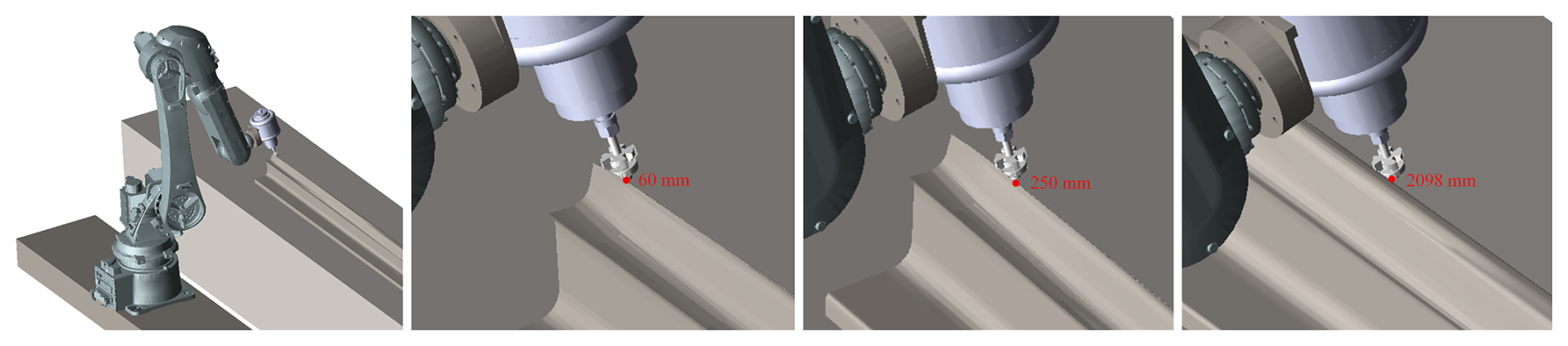
Based on the milling force profile, the process is divided into three segments, as shown in Fig. 4: Segment A (0–60 mm), corresponding to the transition from free to constrained space with minimal force; Segment B (60–250 mm), where the force varies most rapidly; and Segment C (250–2098 mm), corresponding to the maximum force. The proposed algorithm is validated through force-tracking comparisons with and without compliance control.
5.2.1 Segment A
Segment A of the switch rail
Vibration interference occurs at the initial contact between the robot end-effector and the switch rail. In the simulation, normal-force control is applied initially, with the resulting force response curve shown in Fig. 5. Subsequently, comprehensive force control is implemented, and the corresponding force response curve is presented in Fig. 6.
At the initial cutter-rail contact, a pronounced elastic impact occurs, making the thin rail edge prone to overcutting, as shown in Figs. 5 and 6. After implementing force control, although initial contact induces vibration, the amplitude of subsequent vibrations decreases, demonstrating the effectiveness of the control strategy. Performance is evaluated by comparing the mean deviation between the measured and reference milling forces with and without force control, as reported in Table 2. Force control enables accurate tracking in rail segments with small milling force variations and limited interference. Based on the estimated environmental stiffness, the displacement error under composite force control is 42 µm.
5.2.2 Segment B
Segment B of the switch rail
Under normal-force-only control and composite-force control, the force response curves are provided in Figs. 7 and 8, respectively.
The milling force tracking error for section B is evaluated, the results of which are presented in Table 3. Force control effectively achieves force tracking in the segment with the fastest milling force change and interference, as shown in Figs. 7 and 8. Based on environmental stiffness calculations, the displacement error under compound force control is 42 µm.
5.2.3 Segment C
Segment C of the switch rail
Under normal-force-only control and composite-force control, the force response curves are provided in Figs. 9 and 10, respectively.
The tracking error of the force in section C of the switch rail is used to assess the effectiveness of force control, as shown in Table 4. Additionally, force control effectively tracks the force in segments with high milling forces and interference. Based on environmental stiffness calculations, the displacement error under compound force control is 54 µm.
Simulations under diverse milling force regimes show that the proposed compliance controller achieves accurate force tracking. The controller attains this by jointly modulating tangential velocity and normal displacement. Despite feed speed variations and the resulting updates to the normal-force reference, the controller maintains accurate normal-force tracking.
To validate the effectiveness of the proposed FDAFC framework, the experimental platform is configured as follows. As shown in Fig. 11a, the robotic milling system is built on an industrial robot with a positioning repeatability of ±0.05 mm and a maximum working radius of 1617 mm. A six-axis force sensor is used for online force measurement, and the measured signals are sampled at 100 Hz and transmitted to the industrial PC via EtherCAT. Moreover, the proposed compliant milling controller is implemented on the industrial PC equipped with an Intel i7-9700TE CPU and 32 GB RAM.
Since the full-length Chinese no. 9 switch rail exceeds the workspace of the current experimental platform, a 1000 mm section is selected as the workpiece and further divided into three representative segments for long-distance milling tests. The spindle speed is set to 24 000 r min−1, and the initial feed speed is 5 mm s−1. During operation, the robot controller updates the cutter path online to maintain alignment between the cutter side and the top edge of the switch rail, as shown in Fig. 11b. As shown in Fig. 11c, the machined switch rail surface exhibits a smooth and uniform appearance, with no obvious tool marks or force-induced overcutting of the thin edge. Repeated measurements show that the post-milling surface roughness averages 3.2 µm, as illustrated in Fig. 11d, demonstrating satisfactory surface quality for switch rail milling.
The resultant milling force is used as an overall indicator of the milling load to characterize the combined variation in the cutting load. Figure 12 presents the resultant milling force under the cases with and without compound force control in the three representative segments, and the corresponding statistical results are summarized in Table 5.
The mean resultant milling force under compound force control remains close to that of the uncontrolled case across all three segments, whereas the fluctuation level is significantly reduced. As summarized in Table 5, the standard deviation is reduced by 59.9 %, 64.3 %, and 65.4 % in Segments X, Y, and Z, respectively, while the peak-to-peak value is reduced by 45.5 %, 52.7 %, and 55.1 %. These results demonstrate that the proposed FDAFC framework effectively suppresses force fluctuation without noticeably changing the average milling load level, thereby improving the stability of long-distance robotic milling.
To address inconsistent machining quality caused by position control errors and burr effects during the long-feed process of the robotic system, this paper proposes a flexible milling control strategy based on the linear-motor–robot configuration. Robot kinematics and dynamics are formulated using D–H parameters, a damped least-squares pseudo-inverse with L2-weighted null-space optimization, and Newton–Euler inverse dynamics. An FDAFC frame is devised: feed-per-tooth normalization with first-order gain scheduling regulates the tangential force, while RBF-scheduled position-based impedance tracks normal force. Moreover, a coupling law updates the normal-force reference, and Lyapunov-guided adaptation ensures stable, compliant milling. To support analysis, an ADAMS-Simulink model is developed, where the milling force exhibits three distinct regions. Under compound force control, the maximum tracking errors are 6.11 N for tangential force and 4.90 N for normal force. The experimental results confirm that the proposed FDAFC framework can effectively suppress milling load fluctuation and achieve satisfactory surface-finish quality in switch rail milling.
Nevertheless, the current FDAFC framework is formulated based on tangential/normal-force decoupling in the contact frame and does not explicitly model or compensate for the coupled closed-loop interactions between the linear-axis translation and the two force control channels. Future work will investigate an integrated multivariable control strategy that explicitly accounts for these coupling effects to improve multi-axis coordination.
Data supporting this study's findings are available from the corresponding author upon request.
KX: Writing – review and editing, writing – original draft, validation, supervision, resources, methodology, investigation, formal analysis. QL: writing – review and editing, supervision, conceptualization. JL: writing – review and editing, supervision, methodology. WF: visualization, resources, project administration, formal analysis, data curation. ZW: investigation, formal analysis, data curation. JL: investigation, supervision, data curation.
The contact author has declared that none of the authors has any competing interests.
Publisher's note: Copernicus Publications remains neutral with regard to jurisdictional claims made in the text, published maps, institutional affiliations, or any other geographical representation in this paper. The authors bear the ultimate responsibility for providing appropriate place names. Views expressed in the text are those of the authors and do not necessarily reflect the views of the publisher.
This work is supported by the talent fund of Beijing Jiaotong University (grant no. 2024XKRC030) and the National Natural Science Foundation of China (grant nos. 52305005, 52205005).
This paper was edited by Pietro Bilancia and reviewed by two anonymous referees.
Bai, L., Xia, L., and Ge, X.: A Lie group variational integrator in a closed-loop vector space without a multiplier, Mech. Sci., 15, 169–181, https://doi.org/10.5194/ms-15-169-2024, 2024.
Burghardt, A., Szybicki, D., Kurc, K., Muszyńska, M., and Mucha, J.: Experimental study of Inconel 718 surface treatment by edge robotic deburring with force control, Strength Mater., 49, 594–604, https://doi.org/10.1007/s11223-017-9903-3, 2017.
Chen, H., Yang, J., and Ding, H.: Robotic compliant grinding of curved parts based on a designed active force-controlled end-effector with optimized series elastic component, Robot. Comput.-Integr. Manuf., 86, 102646, https://doi.org/10.1016/j.rcim.2023.102646, 2024.
Dong, L., Ma, J., Cao, J., and Wang, D.: Serial–parallel cooperative assembly approach for precision micro-assembly of axial holes, Mech. Sci., 15, 653–665, https://doi.org/10.5194/ms-15-653-2024, 2024.
Ge, J., Cao, D., Liu, W., Deng, Z., Wu, J., Wu, S., Lv, L., and Wang, X.: An online monitoring approach of grinding wheel wear condition for robotic weld grinding based on enhanced CNN-GRU model, Mech. Syst. Signal Process., 241, 113483, https://doi.org/10.1016/j.ymssp.2025.113483, 2025.
González, M., Rodríguez, A., López-Saratxaga, U., Pereira, O., and López de Lacalle, L. N.: Adaptive edge finishing process on distorted features through robot-assisted computer vision, J. Manuf. Syst., 74, 41–54, https://doi.org/10.1016/j.jmsy.2024.02.014, 2024.
Groover, M. P.: Fundamentals of modern manufacturing: materials, processes, and systems, 4th Edn., John Wiley & Sons, Hoboken, NJ, ISBN 978-0-470-46700-8, 2010.
Grossoni, I., Hughes, P., Bezin, Y., Bevan, A., and Jaiswal, J.: Observed failures at railway turnouts: Failure analysis, possible causes and links to current and future research, Eng. Fail. Anal., 119, 104987, https://doi.org/10.1016/j.engfailanal.2020.104987, 2021.
Hogan, N.: Impedance control of industrial robots, Robot. Comput.-Integr. Manuf., 1, 97–113, https://doi.org/10.1016/0736-5845(84)90084-X, 1984.
Jin, S. Y., Pramanik, A., Basak, A. K., Prakash, C., Shankar, S., and Debnath, S.: Burr formation and its treatments – a review, Int. J. Adv. Manuf. Technol., 107, 2189–2210, https://doi.org/10.1007/s00170-020-05203-2, 2020.
Khan, S. G.: Adaptive chaos control of a humanoid robot arm: a fault-tolerant scheme, Mech. Sci., 14, 209–222, https://doi.org/10.5194/ms-14-209-2023, 2023.
Kisilowski, J. and Kowalik, R.: Numerical testing of switch point dynamics – a curved beam with a variable cross-section, Materials, 13, 701, https://doi.org/10.3390/ma13030701, 2020.
Kratěna, T., Vavruška, P., Švéda, J., and Zeman, P.: Workpiece position optimisation in robotic multi-axis machining, Results Eng., 27, 106421, https://doi.org/10.1016/j.rineng.2025.106421, 2025.
Lai, Z., Xiong, R., Wu, H., and Guan, Y.: Integration of visual information and robot offline programming system for improving automatic deburring process, in: 2018 IEEE International Conference on Robotics and Biomimetics (ROBIO), Kuala Lumpur, Malaysia, 12–15 December 2018, IEEE, 1132–1137, https://doi.org/10.1109/ROBIO.2018.8665148, 2018.
Li, Z., Shang, W., and Zhang, B.: Hybrid impedance control of cable-driven parallel robots using adaptive friction compensation, IEEE Trans. Ind. Electron., 72, 703–713, https://doi.org/10.1109/TIE.2024.3409905, 2025.
Lloyd, S., Irani, R. A., and Ahmadi, M.: Precision robotic deburring with simultaneous registration and machining for improved accuracy, quality, and efficiency, Robot. Comput.-Integr. Manuf., 88, 102733, https://doi.org/10.1016/j.rcim.2024.102733, 2024.
Ma, X., Li, H., Xie, Y., Liu, J., Peng, Y., Xie, S., and Luo, J.: Adaptive dynamics-based prescribed-time control for robots formation tracking in task space, IEEE Trans. Syst. Man Cybern. Syst., 55, 6476–6485, https://doi.org/10.1109/TSMC.2025.3579053, 2025.
Mohammed, A., Kvam, J., Onstein, I. F., Bakken, M., and Schulerud, H.: Automated 3D burr detection in cast manufacturing using sparse convolutional neural networks, J. Intell. Manuf., 34, 303–314, https://doi.org/10.1007/s10845-022-02036-6, 2023.
Precup, R.-E., Roman, R.-C., and Safaei, A.: Data-driven model-free controllers, CRC Press, Boca Raton, FL, https://doi.org/10.1201/9781003143444, 2021.
Rahul, M. R. and Chiddarwar, S. S.: Deep reinforcement learning with inverse Jacobian based model-free path planning for deburring in complex industrial environment, J. Intell. Robot. Syst., 110, 4, https://doi.org/10.1007/s10846-023-02030-x, 2024.
Raibert, M. H. and Craig, J. J.: Hybrid position/force control of manipulators, J. Dyn. Syst. Meas. Control, 103, 126–133, https://doi.org/10.1115/1.3139652, 1981.
Shaw, M. C. and Cookson, J. O.: Metal cutting principles, 2nd Edn., Oxford University Press, New York, NY, ISBN 978-0-19-514206-8, 2005.
Tafuro, A., Molinaro, M., Zanchettin, A. M., and Rocco, P.: Self-supervised vision-driven trajectory planning for intelligent robotic deburring, Mach. Intell. Res., 22, 655–676, https://doi.org/10.1007/s11633-025-1560-6, 2025.
Tang, X., Cai, X., Xu, J., and Yang, F.: A full information expression model for track irregularity based on stochastic harmonic functions in vehicle–turnout structure stochastic vibration analysis, Railw. Eng. Sci., 34, 349–369, https://doi.org/10.1007/s40534-025-00381-9, 2026.
Tao, Y., Zheng, J., Lin, Y., Wang, T., Xiong, H., He, G., and Xu, D.: Fuzzy PID control method of deburring industrial robots, J. Intell. Fuzzy Syst., 29, 2447–2455, https://doi.org/10.3233/IFS-151945, 2015.
Tao, Y., Zheng, J., and Lin, Y.: A sliding mode control-based on a RBF neural network for deburring industry robotic systems, Int. J. Adv. Robot. Syst., 13, 8, https://doi.org/10.5772/62002, 2016.
Tiseo, C., Merkt, W., Wolfslag, W., Vijayakumar, S., and Mistry, M.: Safe and compliant control of redundant robots using superimposition of passive task-space controllers, Nonlinear Dyn., 112, 1023–1038, https://doi.org/10.1007/s11071-023-09045-x, 2024.
Villagrossi, E., Cenati, C., Pedrocchi, N., Beschi, M., and Tosatti, L. M.: Flexible robot-based cast iron deburring cell for small batch production using single-point laser sensor, Int. J. Adv. Manuf. Technol., 92, 1425–1438, https://doi.org/10.1007/s00170-017-0232-2, 2017.
Wang, H. H., Wang, W. J., Han, Z. Y., Wang, Y., Ding, H. H., Lewis, R., Lin, Q., Liu, Q. Y., and Zhou, Z. R.: Wear and rolling contact fatigue competition mechanism of different types of rail steels under various slip ratios, Wear, 522, 204721, https://doi.org/10.1016/j.wear.2023.204721, 2023.
Wang, K., Zhu, H., Xu, J., Bai, T., Tian, C., Qian, Y., Gao, Y., Chen, R., Wang, P., and Liu, Y.: Study on the damage mechanism of high-speed turnout switch rails on large ramps, J. Cent. South Univ., 32, 288–303, https://doi.org/10.1007/s11771-025-5858-x, 2025a.
Wang, Z. and Lei, Z.: Analysis of influence factors of rail corrugation in small radius curve track, Mech. Sci., 12, 31–40, https://doi.org/10.5194/ms-12-31-2021, 2021.
Wang, Z., Zou, L., Li, J., Zhang, J., and Wang, W.: Point-driven toolpath curve and orientation smoothing in robotic belt grinding for turbine blade, Robot. Comput.-Integr. Manuf., 96, 103046, https://doi.org/10.1016/j.rcim.2025.103046, 2025b.
Xiao, Q., Yang, Y., Chang, C., and Li, D.: Monitoring and evaluation of high-speed railway turnout grinding effect based on field test and simulation, Appl. Sci., 13, 9177, https://doi.org/10.3390/app13169177, 2023.
Xie, Z., Jin, L., Luo, X., Hu, B., and Li, S.: An acceleration-level data-driven repetitive motion planning scheme for kinematic control of robots with unknown structure, IEEE Trans. Syst. Man Cybern. Syst., 52, 5679–5691, https://doi.org/10.1109/TSMC.2021.3129794, 2022.
Zhang, Y., Liu, H., Cheng, W., Hua, L., and Zhu, D.: A novel trajectory planning method for robotic deburring of automotive castings considering adaptive weights, Robot. Comput.-Integr. Manuf., 86, 102677, https://doi.org/10.1016/j.rcim.2023.102677, 2024.
Zhao, J., Li, Y., Li, Y., Pei, B., Yu, Z., and Dong, Z.: A predefined-time radial basis function (RBF) neural network tracking control method considering actuator faults for a new type of spraying robot, Mech. Sci., 16, 51–60, https://doi.org/10.5194/ms-16-51-2025, 2025.
Zhou, R., Zhao, T., Yang, H., and Su, Q.: An online dynamic parameter identification approach for robotic manipulator with reformulated physical feasibility, IEEE Trans. Instrum. Meas., 74, 1–14, https://doi.org/10.1109/TIM.2025.3573017, 2025.
Zong, L., Jiang, C., Du, H., Luo, Y., and Cong, Y.: Interaction force control of industrial manipulators via neural network-based integral terminal sliding mode control algorithm, Nonlinear Dyn., 113, 26361–26375, https://doi.org/10.1007/s11071-025-11483-8, 2025.
- Abstract
- Introduction
- Configuration of the linear-motor–robot milling system
- Kinematic–dynamic modeling of the robot system
- Feed–displacement dual-channel adaptive force control
- Simulation of adaptive milling force control
- Experimental validation in robotic switch rail milling
- Conclusions
- Data availability
- Author contributions
- Competing interests
- Disclaimer
- Financial support
- Review statement
- References