the Creative Commons Attribution 4.0 License.
the Creative Commons Attribution 4.0 License.
 | 14 Apr 2026
Active disturbance rejection control of tractor cab suspension with a multi-state adjustable damper
ZhenYing Liang
Weiqi Chen
Bo Guo
Yihan Huang
This study presents an advanced semi-active vibration control strategy for tractor cab suspension systems based on active disturbance rejection control (ADRC). A novel multi-state adjustable damper, capable of real-time switching between four damping modes via dual solenoid valves, is developed to adapt to varying vibration conditions. A comprehensive 7-degree-of-freedom (7-DOF) dynamic model of the tractor cab, incorporating vertical, pitch, and roll motions, is established to characterize the vibration behavior. Based on this model, an ADRC controller is designed to suppress cab vibrations caused by both road surface irregularities and the engine-induced profile. The control forces computed by ADRC are allocated to four corner dampers through a decoupling-based force distribution method, enabling mode switching through solenoid valve control signals. Simulation results under the ISO Class D road profile demonstrate that the proposed ADRC strategy significantly reduces the RMS values of vertical, pitch, and roll accelerations by up to 57.1 %, 67.1 %, and 65.4 %, respectively, compared with conventional fuzzy PID and skyhook control methods. Furthermore, according to the ISO 2631-1 evaluation, the overall frequency-weighted acceleration was reduced by 60.2 % and 46.7 % compared with fuzzy PID and skyhook control, respectively, confirming a significant improvement in ride comfort classification. Additionally, the proposed system effectively limits dynamic suspension travel and avoids excessive valve switching, demonstrating improved ride comfort and strong system robustness.
- Article
(5657 KB) - Full-text XML
- BibTeX
- EndNote


Operators of agricultural machinery, including tractor and specialized equipment drivers, are frequently exposed to continuous vibrations caused by uneven terrain. Such exposure has been associated with adverse health effects, including reduced alertness, fatigue, and impaired driving performance. Prolonged exposure to vibration is strongly correlated with musculoskeletal disorders, particularly lower back pain, spinal discomfort, and other biomechanical disorders (de la Hoz-Torres et al., 2021; Lecocq et al., 2022; Schneider et al., 2023; Barač et al., 2025). To mitigate these risks, various vibration isolation technologies for tractor cabs have been proposed, including passive (Liao et al., 2021; Atindana et al., 2023), semi-active (Bai et al., 2023; Ni and Nguyen, 2023), and active suspension systems (Na et al., 2021; Guo et al., 2023). Although active suspension systems are effective, their complexity and high cost are inconsistent with the cost-sensitive design requirements of the agricultural machinery industry, thereby limiting their practical application in such settings (Chen et al., 2025). As a result, passive and semi-active cab suspension systems are more commonly employed in agricultural tractors. Passive systems have historically dominated the market due to their simplicity and reliability; however, their inability to adapt to varying terrain conditions and complex vibrations limits their effectiveness in improving cab ride comfort. Semi-active suspension has therefore emerged as a viable compromise, combining structural simplicity with real-time adaptability (Soliman and Kaldas, 2021; Maciejewski et al., 2023).
Existing semi-active control methods can be classified into four categories: (1) classical skyhook and groundhook algorithms (Díaz-Choque et al., 2021); (2) conventional control methods, such as PID control; (3) modern control approaches, including linear quadratic regulators (LQRs), optimal control, and robust control; and (4) intelligent control methods, such as adaptive control, fuzzy control, and neural-network-based control. For example, Shen et al. (2026) proposed a semi-active air ISD suspension with frequency-varying negative stiffness, offering significant improvements in vibration isolation for vehicle systems under varying conditions. Additionally, Shen et al. (2025) applied a fractional-order SH-GH strategy for vibration control in vehicle ISD suspensions, which enhances control system performance and offers greater adaptability to dynamic road conditions. Specifically, Chen et al. (2024) proposed an improved hybrid control algorithm that combines skyhook and groundhook strategies for negative-stiffness suspension systems. Simulation results demonstrated that the proposed approach significantly improved ride comfort. Additionally, Lu et al. (2022) developed a coordinated skyhook-LQR control strategy for semi-active vehicle suspension systems to improve ride comfort, while Yang et al. (2025) combined the skyhook algorithm with an adaptive fuzzy sliding mode controller to achieve dual suppression of vibrations and impacts. Based on sliding mode control (SMC), Maciejewski et al. (2023) analyzed the actual vibration inputs experienced in agricultural tractor cabs and applied an SMC strategy to improve driver comfort. Zhang et al. (2024) investigated whole-vehicle semi-active suspension systems under various road disturbances using a combination of optimal control and SMC, along with a hierarchical decoupling strategy to enhance ride smoothness. In the domain of intelligent control, Cai et al. (2025) proposed a composite control strategy combining model-aided estimation and parameter-adaptive optimization with BP-PID control for attitude control of agricultural machinery platforms. Hu et al. (2025) applied a BP neural network in combination with a genetic algorithm (GA) to perform nonlinear state reconstruction in vehicle seat suspension systems, aiming to ensure dynamic observability. Moreover, fuzzy control is frequently applied in cab suspension systems. For example, to mitigate multi-directional impact vibrations experienced by drivers of off-road vehicles, an optimized fuzzy skyhook control method was implemented in a seat damping suspension system in Zhang et al. (2023), effectively reducing vibrations at the seat and chassis levels. In Tao and Liu (2021), a variable universe fuzzy control approach was developed for the semi-active cab suspension of a wheel loader, incorporating a damper with multiple damping mode switching capabilities. For nonlinear semi-active suspension systems subject to varying loads and frequency-domain constraints, a hybrid damping control strategy based on a Kalman observer was investigated in Jiang et al. (2024). A feedback linearized Kalman observer based on differential geometry theory was designed to enhance the dynamic performance of nonlinear MR semi-active suspension systems. However, these methods often rely on prior knowledge of the suspension system (e.g., neural networks), measurable states (e.g., skyhook velocity), or empirical design experience (e.g., fuzzy rules), which poses significant challenges for practical engineering applications.
In addition to suspension characteristics, other critical factors affecting the damping performance of vehicle suspension systems include road conditions and driving operations. Therefore, it is necessary to design damping control strategies capable of online estimation and compensation for uncertainties within the suspension system. To this end, a hierarchical control strategy was proposed in Diao et al. (2025), in which the upper-level controller employs a sliding mode controller based on a nonlinear disturbance observer, while the lower-level controller utilizes a back-stepping adaptive control approach to achieve coordinated control of suspension dynamic displacement and sprung mass acceleration in nonlinear uncertain suspension systems. In Sun et al. (2024), a road roughness estimation method was developed based on accelerometer signals, in which acceleration and velocity inputs were used to train a neural network. The trained model subsequently generated the root mean square value of the power spectral density to estimate road roughness. Li et al. (2025) proposed a novel H∞ gain-scheduled state feedback controller design method, which achieved high-precision estimation of both road profiles and system states. Additionally, a suspension state observer was introduced in Ji et al. (2025) to estimate unmeasurable signals required by the damper control algorithm. Moreover, ADRC has been recognized as a disturbance rejection control strategy that is largely model independent, easy to implement, and highly suitable for practical engineering applications (Carreño-Zagarra et al., 2024; Yu-Hao et al., 2025). At the core of ADRC, the extended state observer (ESO) requires only minimal model information (Herbst and Madonski, 2025) and is capable of estimating both unmeasurable system states and external disturbances.
Based on this concept, ADRC has been widely applied in both active and semi-active suspension systems. For active suspension systems, ADRC has been integrated with dynamic fuzzy logic techniques in Nguyen (2025), and its performance has been evaluated in comparison with conventional control strategies. However, unsprung mass was not considered in the controller design. Yang et al. (2024) proposed a controllable dynamic inertia suspension system based on ADRC to enhance passenger comfort and vibration isolation performance in full-vehicle active suspension systems. Tao et al. (2025) introduced a control strategy that integrates an adaptive neuro-fuzzy inference system (ANFIS) with ADRC to enhance vibration isolation performance in seat suspension systems. For electromagnetic suspension systems, an ADRC algorithm with parameter adaptation via backpropagation neural networks was proposed in Fu et al. (2024). Furthermore, in Bin and Wei (2024), ADRC was combined with mixed-integer quadratic programming (MIQP) to improve ride comfort in loader seat suspension systems, taking into account suspension nonlinearity and actuator saturation effects. For semi-active suspension systems, Wang et al. (2024) considered the various disturbances experienced by maglev trains during operation and proposed a model-aided modified ADRC (MADRC) method, which exhibited strong disturbance suppression capabilities for suspension system load variations. In addition to variable damping strategies, recent studies have also highlighted the importance of variable-stiffness mechanisms in vibration isolation. For example, Yu et al. (2025) developed a semi-active suspension system that integrates both adjustable damping and stiffness, demonstrating improved vibration suppression performance under complex road profiles. Similarly, Wos and Dziopa (2024) designed and experimentally verified a magnetorheological elastomer (MRE)-based isolator with tunable stiffness, which provided enhanced adaptability to varying profile frequencies. These works indicate that variable stiffness, when combined with variable damping, offers a promising pathway to further reduce vertical acceleration and improve ride comfort. Although our present study focuses on a multi-state damping approach, future research could benefit from integrating stiffness variability into the suspension architecture.
Despite extensive research on semi-active suspension systems, several critical gaps remain unaddressed. First, most existing studies on ADRC-based vibration control have primarily focused on quarter-car or seat suspension models, whereas systematic investigations on tractor cab suspension systems with complex multi-degree-of-freedom dynamics are still scarce. Second, although various semi-active dampers have been explored, few works consider a multi-state adjustable damper capable of discrete mode switching, which can provide a wider damping range under diverse excitation conditions. Third, many prior ADRC applications neglect the combined influence of road irregularities and engine-induced vibrations, which represent significant and concurrent disturbance sources in agricultural vehicles. Finally, little attention has been given to the control allocation problem, i.e., mapping ADRC's virtual control forces into discrete damper switching commands, which is essential for practical implementation. Addressing these gaps, this study develops a 7-DOF tractor cab suspension model incorporating a multi-state adjustable damper and proposes an ADRC-based control allocation strategy, thereby advancing the state of the art in vibration control for agricultural machinery. Based on the above discussion, the unmeasurability of vehicle states and the ability to suppress uncertainties and disturbances are identified as key concerns in semi-active cab suspension control. Therefore, considering the weak model dependence, strong disturbance rejection capability, and simplicity of parameter tuning in ADRC, ADRC is introduced in this study for tractor cab suspension control to realize adaptive vibration attenuation in semi-active suspension systems. The main contributions of this work are summarized as follows:
-
development of a novel multi-state adjustable damper with four discrete damping modes realized by dual solenoid valves, enabling a wide damping range and adaptive switching under varying excitation conditions;
-
formulation of a comprehensive 7-DOF tractor cab suspension model that simultaneously incorporates vertical, pitch, and roll dynamics of the cab, frame, and engine, providing a realistic platform for vibration control analysis;
-
design of an ADRC-based semi-active control strategy that estimates and compensates for total disturbances in real time, addressing the combined effects of road irregularities and engine-induced excitations;
-
proposal of a decoupling-based control allocation method that translates ADRC's continuous virtual control forces into practical solenoid valve-switching commands, ensuring effective implementation in discrete multi-mode dampers.
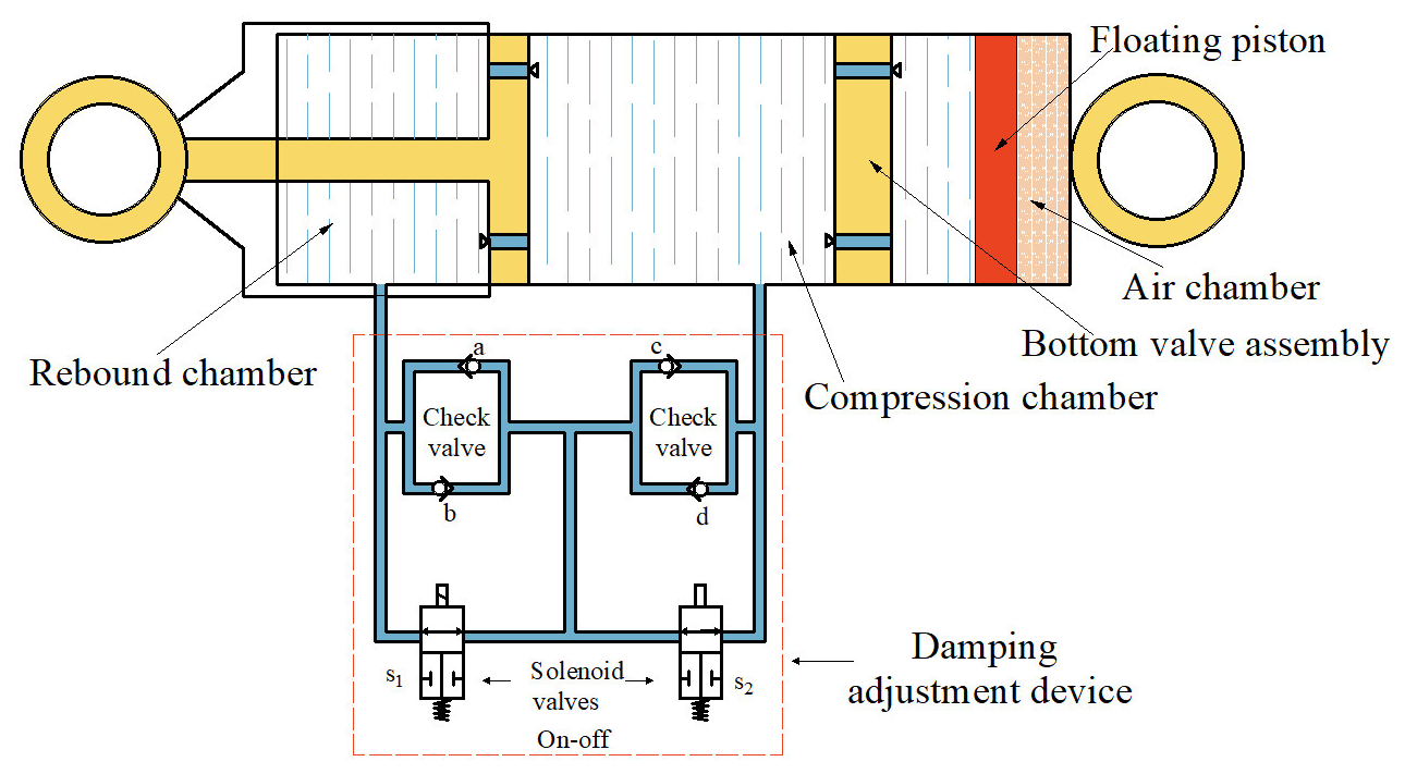
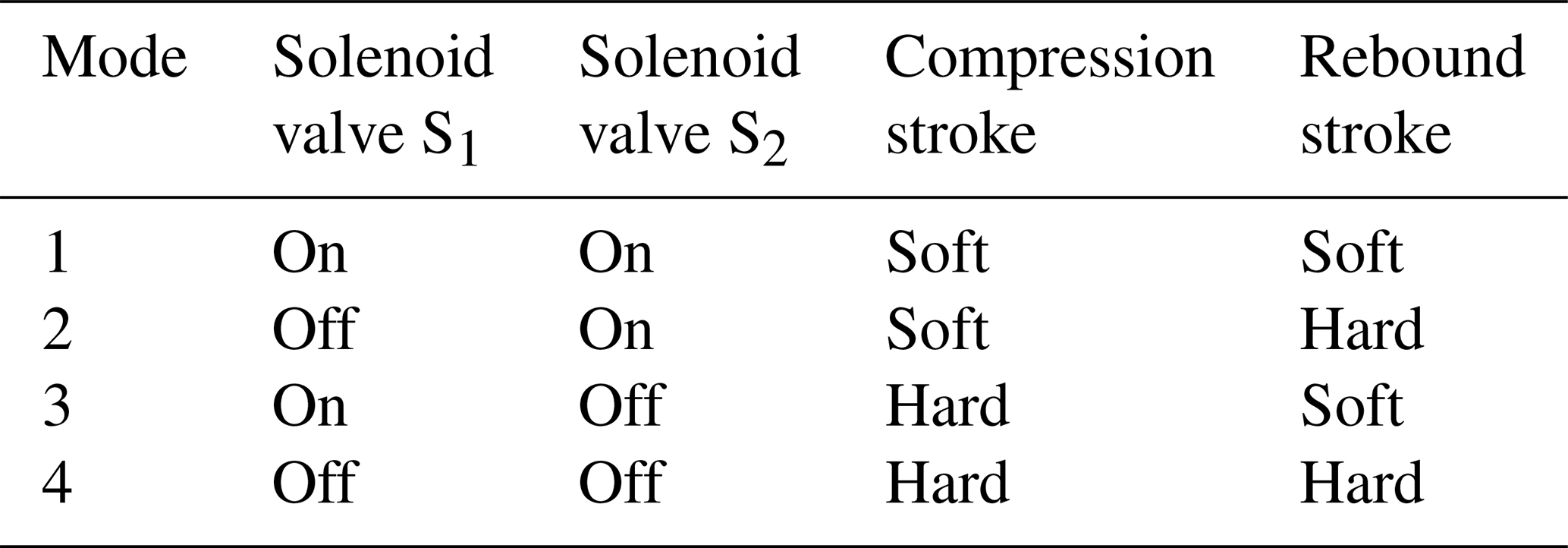
In this study, a novel multi-state adjustable damper is introduced into the tractor cab suspension system. As shown in Fig. 1, the damper employs two high-speed solenoid valves, S1 and S2, to regulate the oil flow paths between the compression and rebound chambers. By changing the on/off combinations of these two valves, four discrete damping modes can be realized: soft–soft, soft–hard, hard–soft, and hard–hard, as summarized in Table 1.
Table 1Damping modes and operating states of the adjustable damper.
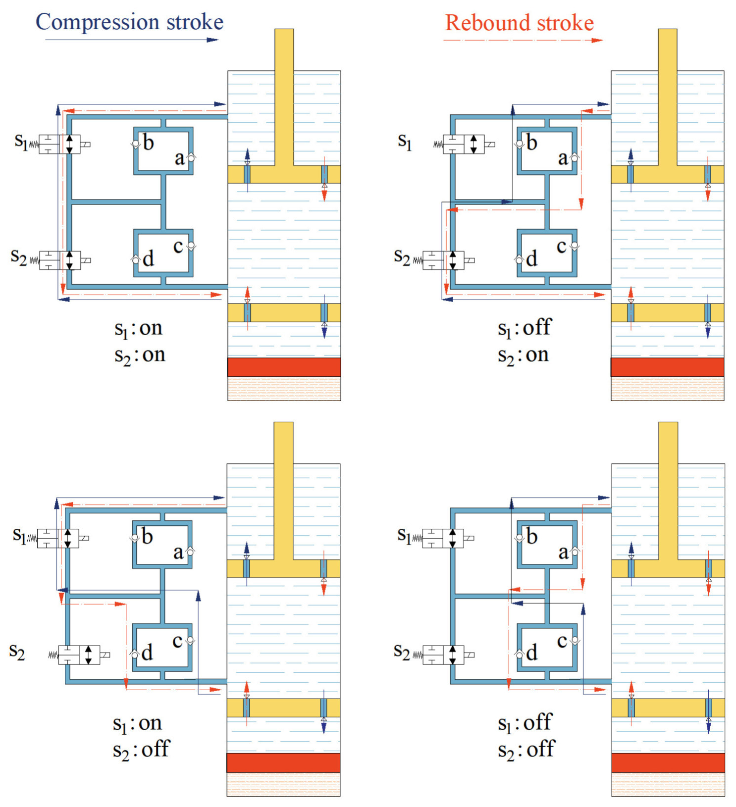
Damping variation is achieved by redirecting the fluid through different combinations of internal check valves and throttling paths, as illustrated in Fig. 2. When both solenoid valves are open, the fluid circulates through the least restrictive path, resulting in relatively low damping forces during both compression and rebound. In contrast, when both valves are closed, the flow is forced to pass through more restrictive paths and additional check valves, thereby producing the highest damping level. When only one valve is closed, asymmetric damping characteristics are generated, leading to either a soft–hard or hard–soft mode, as summarized in Table 1. In this way, the proposed damper provides a wider and more flexible damping range than a conventional fixed-parameter damper, making it suitable for semi-active vibration control in tractor cab suspension systems operating under varying excitation conditions.
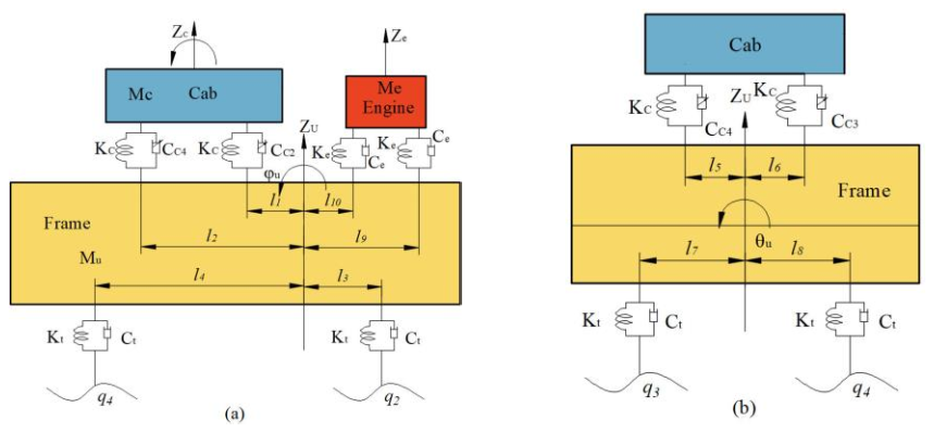
Figure 37-DOF vibration model of the tractor cab suspension system: (a) main view of the tractor vibration model and (b) left view of the tractor vibration model.
3.1 Dynamic modeling of the cab suspension system
Based on the vibration characteristics of tractors, a 7-DOF dynamic model of the entire vehicle is established, as illustrated in Fig. 3. The 7 degrees of freedom include the vertical, pitch, and roll motions of the tractor frame; the vertical, pitch, and roll motions of the cab; and the vertical motion of the engine.
As shown in Fig. 3, Mc, Mu, and Me represent the masses of the cab, frame, and engine, respectively. Zc and Zu represent the vertical displacements of the centers of mass of the cab and frame, respectively. Fe denotes the vertical force generated by engine-induced rotational vibrations, while Ze is the vertical displacement at the engine's center of mass. ke and ce refer to the stiffness and damping coefficients of the engine mount. kc represents the stiffness coefficient of the suspension system at the four corners of the tractor cab, and cc1, cc2, cc3, and cc4 represent the variable damping coefficients at the four corners of the cab suspension system. φc and φu represent the pitch angles of the cab and frame, while θc and θu represent the corresponding roll angles. l1 and l2 are the vertical distances from the frame's center of mass to the front and rear cab suspensions, whereas l3 and l4 indicate the distances to the front and rear tractor wheels. l5 and l6 are the distances to the left and right cab suspensions and l7 and l8 to the left and right tractor wheels. l9 and l10 represent the distances to the front and rear engine mounts, respectively. Finally, kt and ct refer to the equivalent stiffness and damping coefficients of the tractor tires, and q1, q2, q3, and q4 are the vertical displacement inputs at the left-front, right-front, left-rear, and right-rear wheels of the tractor, respectively.
Based on Newtonian mechanics, the dynamic equations for each degree of freedom in the tractor vibration model are established separately. The vertical vibration model of the tractor frame is first established as follows(Tao and Liu, 2021):
where Ft1, Ft2, Ft3, and Ft4 represent the vertical forces acting on the four tractor tires; Fc1, Fc2, Fc3, and Fc4 represent the vertical forces exerted by the suspension system at the four corners of the cab; and Fe1 and Fe2 represent the vertical forces generated by the front and rear engine mounts, respectively. Assuming that the center of mass of the cab is located at the geometric center, the pitch and roll vibration models of the tractor frame can be derived based on the resolution of the above-mentioned forces (Tao and Liu, 2021):
where Iuφ and Iuθ represent the pitch and roll moments of inertia of the loader frame, respectively.
Similarly, the mathematical equations describing the vertical, pitch, and roll vibrations of the tractor cab can be derived as follows (Tao and Liu, 2021):
where Icφ and Icθ represent the pitch and roll moments of inertia of the loader cab, respectively, while lφ and lθ denote half the vertical distance between the front and rear suspensions and between the left and right suspensions of the cab, respectively.
The mathematical equation representing the vertical motion degree of freedom of the engine is given as follows (Tao and Liu, 2021):
where me represents the engine mass, and the vertical force Fe generated during engine rotation is induced by internal engine vibrations. This force is considered an external profile to the system and will be modeled and analyzed in conjunction with the engine operating process.
By combining the aforementioned equations, a 7-DOF vibration model of the tractor incorporating the cab suspension system is ultimately established. The specific expression for the dynamic suspension travel at the four corners of the cab is given as follows (Tao and Liu, 2021):
where fdx1, fdx2, fdx3, and fdx4 represent the dynamic suspension travels at the four corners of the cab, respectively.
3.2 Development of a multi-state switching damping model for the shock absorber
By controlling the on/off states of two solenoid valves, the system is capable of realizing four damping modes and eight damping states, thereby generating the corresponding damping coefficients of the shock absorber for each operating state. For the rebound and compression strokes, the relationships between the damping coefficients of the shock absorber and the solenoid valve-switching states are established separately as follows:
where δ1 and δ2 are logical variables representing the on/off states of the high-speed solenoid valves S1 and S2, cf and cy represent the damping coefficients of the damper during the rebound and compression strokes, respectively; cf1, cf2, cf3, and cf4 represent the rebound damping coefficients under damping modes 1–4; and cy1, cy2, cy3, and cy4 correspond to the compression damping coefficients in modes 1, 2, 3, and 4, respectively. The values of these variables are determined according to the valve-switching states, as described by the following relationships:
Based on Eq. (6), the expressions for the damping coefficients of the dampers at the four corners of the tractor cab suspension system are further derived as follows:
where cc1, cc2, cc3, and cc4 represent the damping coefficients of the dampers at the four corners of the tractor cab suspension system, and δfc1, δfc2, δfc3, and δfc4 represent logical variables indicating whether the corresponding dampers are operating in the rebound or compression stroke. Their values are determined by the following expressions:
By simultaneously solving Eqs. (6) to (9), a mathematical relationship is established between the damping coefficients of the multi-state switchable damper, the switching states of the solenoid valves, and the operating stroke phase of the damper. This establishes a theoretical foundation for the subsequent design of the damping control strategy.
3.3 Excitation modeling of the cab suspension system
Through analysis of the vibration model of the tractor cab suspension system, it is found that the excitation induced by engine rotational vibration has a significant influence on the overall vibration response of the tractor. Therefore, in order to accurately represent the actual vibration characteristics of the tractor, both a road roughness excitation model considering four-wheel correlation and an engine-induced vibration excitation model are developed.
3.3.1 Stochastic road profile modeling with four-wheel correlation
With the widespread adoption of vehicle vibration control systems, vibration analysis is frequently conducted in the time domain; therefore, the road roughness excitation in the vibration model should also be expressed in the time domain. According to relevant literature, when constructing a time-domain model of single-wheel road roughness excitation, a lower cut-off frequency f0 is typically introduced into the road spectral density function, resulting in the following time-domain expression for road roughness (Múčka, 2018):
where q(t) represents the time-domain displacement input of road roughness, Gq(n0) represents the geometric mean of the road roughness coefficient corresponding to the road class, v is the vehicle travel speed, and w(t) denotes a zero-mean Gaussian white noise process.
Based on the functional relationship among the input spectral densities of road excitations acting on the four wheels of the tractor and the approximate fitting of the correlation function between the left and right wheel tracks, the correlation characteristics of the road inputs for the left and right wheels are derived as follows:
where q1(t) and q2(t) represent the time-domain random road inputs for the left and right front wheels, respectively. The track width between the left and right wheels is denoted by d, and n0 refers to the spatial cut-off frequency of the road surface, with a typical value of 0.01 m−1.
In this study, only the condition of uniform linear motion of the tractor is considered. Therefore, the road inputs for the rear wheels are assumed to follow the same trajectory as those for the front wheels, with a certain time delay. Based on the road input model for the left front wheel, the mathematical expression of the road input model for the left rear wheel, q3(t), is given as follows:
where represents the time delay between the front and rear wheel excitations, where l is the wheelbase between the front and rear axles. The transfer function between q3(t) and q1(t) can be approximated using a second-order Padé approximation, through which the state-space expression representing the correlation between the front and rear wheel inputs can be derived:
3.3.2 Engine vibration excitation modeling
According to relevant literature, the engines commonly used in tractors are typically vertical four-stroke engines. Based on the force analysis of a single-cylinder engine, a rotational vibration excitation model is established by comprehensively considering both the rotating and the reciprocating inertial forces. For an in-line four-cylinder engine, the rotating inertial forces along the Z axis and Y axis are calculated as follows:
As shown in Eq. (14), the rotational inertial forces of a vertical four-stroke engine along the Z axis and Y axis are negligible (approximately equal to zero). Therefore, during the excitation process of engine rotational vibration, these rotational inertial forces can be neglected. The calculation of reciprocating inertial force can be divided into two components, with the first-order reciprocating inertial force being calculated as follows:
The second-order reciprocating inertial force is calculated as follows:
Based on Eqs. (15) and (16), it can be determined that, during tractor operation, the inertial force generated by the rotational and reciprocating motion of the piston–crank–connecting rod mechanism is primarily dominated by the second-order inertial force produced by the reciprocating motion of the equivalent mass m1 located at the piston pin.
4.1 System model and control objectives
The tractor cab suspension is modeled as a 7-DOF system that comprises the bounce, pitch, and roll motions of the cab and frame, along with the vertical motion of the engine. Specifically, the DOFs are the following:
frame (chassis): vertical (bounce), pitch, and roll motions of the main tractor frame;
cab: vertical (bounce), pitch, and roll motions of the cab relative to the frame (supported at four corner mounts);
engine: vertical motion of the engine on its mounts (engine-induced vibration).
The tractor cab suspension is modeled as a 7-DOF system comprising bounce, pitch, and roll motions of the cab and frame, along with the vertical motion of the engine. The cab is supported at four corners by semi-active dampers with discrete mode switching capability.
The primary control objective is to enhance ride comfort by minimizing the root mean square (RMS) values of the cab's vertical acceleration, as well as its pitch and roll accelerations, which are directly related to ISO 2631 ride comfort standards. Since cab angular motions (pitch and roll) can significantly amplify the vertical displacement at the driver's seat, suppression of these dynamics is also included in the control objective.
The system is subjected to two main disturbance sources: (1) road irregularities modeled as ISO Class D stochastic excitation with front–rear and left–right correlation and (2) engine-induced vibrations modeled as periodic excitations from reciprocating inertial forces. The control inputs are the four dampers, which can only provide dissipative forces in discrete modes through valve switching. This makes the problem a nonlinear, semi-active multi-input multi-output (MIMO) control problem.
4.2 ADRC-based damping control of the tractor cabin suspension system
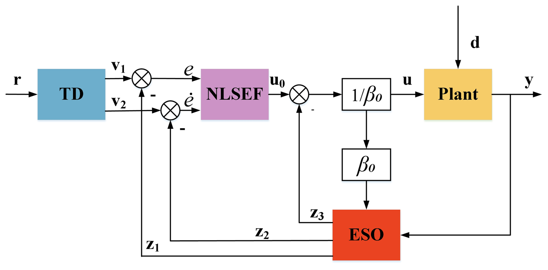
The ADRC framework consists of three main modules: (i) a tracking differentiator (TD) that generates smooth reference signals, (ii) an extended state observer (ESO) that estimates both the system states and the total disturbances, and (iii) a nonlinear state error feedback (NLSEF) law that regulates the system behavior while compensating for disturbances in real time. The block diagram of the ADRC controller is illustrated in Fig. 4 (Jin et al., 2020; Gao et al., 2024).
In this study, the tractor cab's bounce, pitch, and roll motions are each treated as second-order subsystems. The ESO estimates the motion states and the lumped disturbances caused by road irregularities, engine excitation, and model uncertainties. The NLSEF then computes control actions to suppress these vibrations, while the TD smooths reference signals where needed.
To design the ADRC, the cab suspension dynamics are first expressed in a standard second-order form with an augmented disturbance state. Taking the cab bounce motion as an example, the equation of motion can be expressed as follows:
where Zc is the cab's vertical displacement (relative to the ground or an equilibrium), Zu is the frame (unsprung chassis) vertical displacement, and kcab is the total stiffness of the cab mounts, which can be rearranged as
Introducing a nominal model coefficient az and an estimated input gain b0z while lumping all uncertainties and external excitations into a total disturbance term dz, the dynamics become
Similar expressions can be derived for cab pitch and roll motions. For clarity, the bounce (Zc), pitch (ϕc), and roll (θc) motions of the cab are formulated in a unified vector form. The system output and control input vectors are defined as
The dynamics of the three channels can then be compactly written as
where and . The disturbance vector d lumps all unmodeled dynamics and external excitations, including road-induced chassis motion and engine vibrations.
4.3 Design of ESO module of ADRC controller
For each motion channel, the ESO is designed to estimate both the system states and the corresponding lumped disturbance. In compact vector form, the augmented state is defined as (Tao et al., 2025)
The ESO can then be constructed as follows:
where , and L is a block-diagonal observer gain matrix. Each channel adopts pole placement of (s+ωo)3, yielding the following observer gains:
This structure allows the ESO to reconstruct the total disturbance vector in real time, thereby providing the basis for effective disturbance rejection within the ADRC framework. The detailed derivations are presented in Appendix A.
4.4 Design of NLSEF module of ADRC controller
The NLSEF computes a preliminary control signal based on the tracking errors between the reference input and the estimated system output. The error vectors are defined as
A diagonal PD-type feedback law is adopted:
where are feedback gains, and fal(⋅) is a nonlinear function:
This structure ensures that, for small errors, the effective gains approximate the baseline values, avoiding excessive control effort; for large errors, the gains are increased adaptively, improving disturbance rejection and transient performance.
Substituting into the control law yields
Finally, the actual control input is compensated for by the ESO disturbance estimate:
This nonlinear gain formulation highlights the adaptive nature of NLSEF, where feedback intensity is automatically adjusted according to error magnitudes. The approach balances control robustness with actuator effort, thereby ensuring effective vibration suppression across various road and engine excitation conditions. Detailed proofs of stability and derivations are included in Appendix A.
4.5 Control allocation of the four dampers in the tractor cab suspension system
The ADRC controller generates virtual control inputs , which correspond to the desired generalized forces in bounce, pitch, and roll directions. These control inputs must be distributed to the four semi-active dampers located at the cab corners (front-left, front-right, rear-left, rear-right).
Let the damper command vector be defined as
where each element represents the equivalent control demand (force or mode command) applied to a corner damper. The mapping between generalized control forces and individual damper inputs can be expressed as
where T is the allocation matrix determined by the geometry of the cab suspension. A typical formulation is given as follows:
with lx and ly denoting the half-lengths of the cab in the longitudinal and lateral directions, respectively. The following applies in this formulation:
-
The first column distributes the bounce control force equally to all four dampers.
-
The second column introduces opposite effects between front and rear dampers to generate a pitch moment.
-
The third column applies opposite effects between left and right dampers to generate a roll moment.
Finally, each damper's continuous demand uij is converted into a discrete valve-switching mode (soft–soft, soft–hard, hard–soft, hard–hard) according to predefined thresholds. The control mapping is implemented as follows:
-
Normalization. Each damper demand uij is scaled to the range of achievable damping forces.
-
Quantization. The normalized demand is compared against three threshold levels, { V1, V2, and V3 }, which divide the input range into four regions.
-
Voltage command. The damper is driven by a voltage pair (VS1, VS2) corresponding to the selected region, where S1 and S2 denote the two solenoid valves. For example,
-
soft–soft: (VS1, VS2)= (0, 0)
-
soft–hard: (VS1, VS2)= (0, VH)
-
hard–soft: (VS1, VS2)= (VH, 0)
-
hard–hard: (VS1, VS2)= (VH, VH),
where VH is the rated high-voltage level of the valve driver.
In this way, the continuous ADRC outputs are systematically translated into discrete voltage signals for the solenoid valves. This ensures that the controller's virtual forces are effectively realized as mode-switching actions in the multi-state adjustable damper.
5.1 Simulation analysis of MR damper inverse modeling
To validate the performance advantages of the ADRC control strategy, a comprehensive comparative simulation analysis is conducted, with the fuzzy PID and skyhook control strategies serving as benchmark methods. Based on the previously developed four-wheel correlated stochastic road excitation model, the tractor is assumed to travel at a constant speed of 5 m s−1 over a Class D road profile (the road profile inherently contains random fluctuations, measurement-like noise, and intermittent high-amplitude disturbances) (Múčka, 2018), as illustrated in Fig. 5. The road input is modeled according to ISO 8608, using a Class D profile, which corresponds to severe road roughness conditions. The reference spatial frequency was set as n0=0.1 m−1, with a roughness coefficient m3 and waviness index ω=2. The spatial power spectral density is given by . For a forward speed of 5 m s−1, these spectral characteristics were converted into time-domain base excitation inputs at the four wheel contact points. This modeling approach ensures consistency with ISO 8608 definitions and provides a representative severe-road excitation for tractor cab suspension analysis. The key parameters involved in the control system simulation are summarized in Table 2. To ensure a fair comparison among different control strategies, all controllers are evaluated under identical simulation conditions used for fuzzy PID, skyhook, and the proposed ADRC controller, summarized in Table 3. The vehicle and suspension parameters used in this study are consistent with those reported in our previous work (Bin and Wei, 2024), which have been experimentally validated. All simulations were performed under identical road excitation and sampling conditions to guarantee consistency.
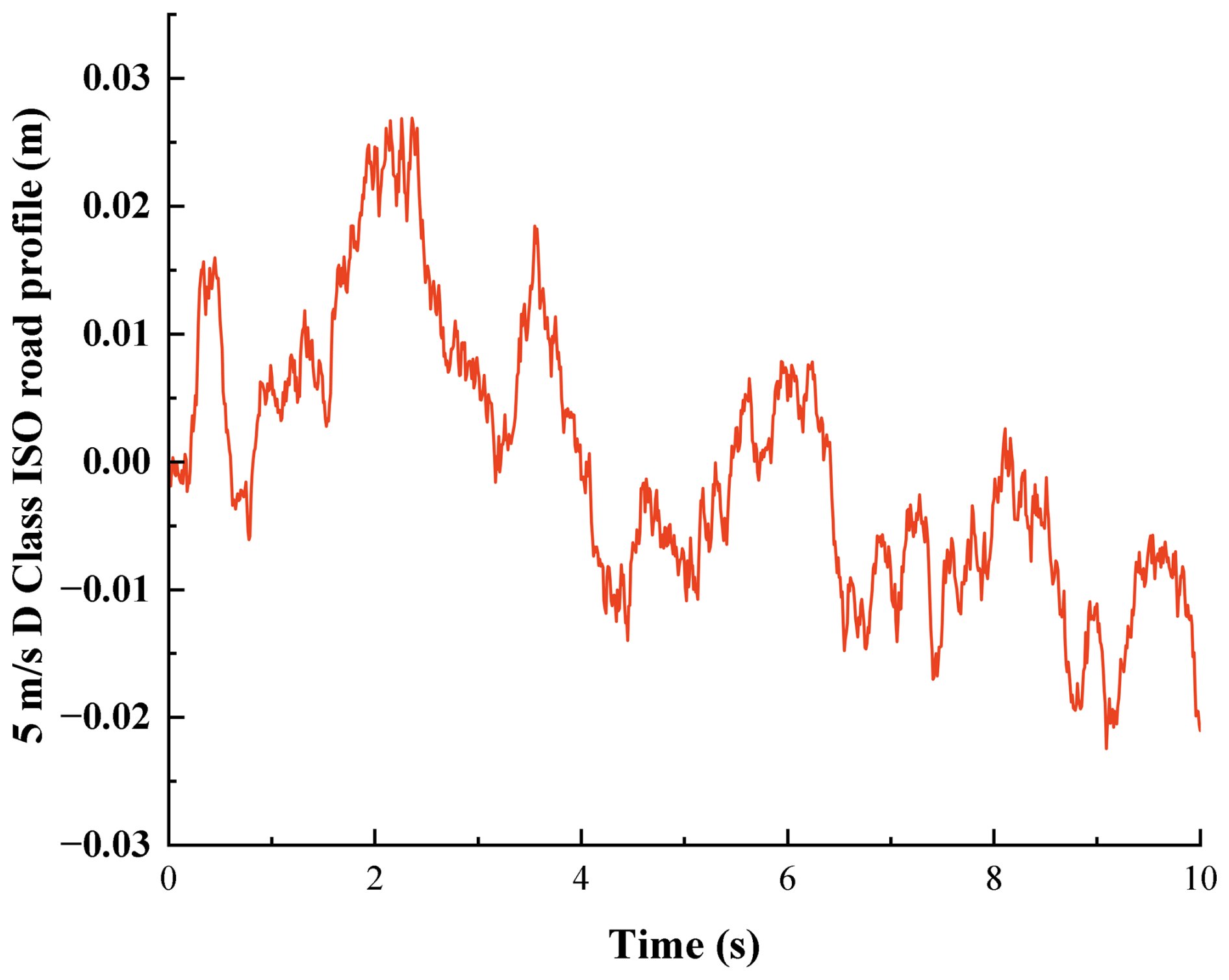
Table 2The key parameters of the damping multi-state switching damper.
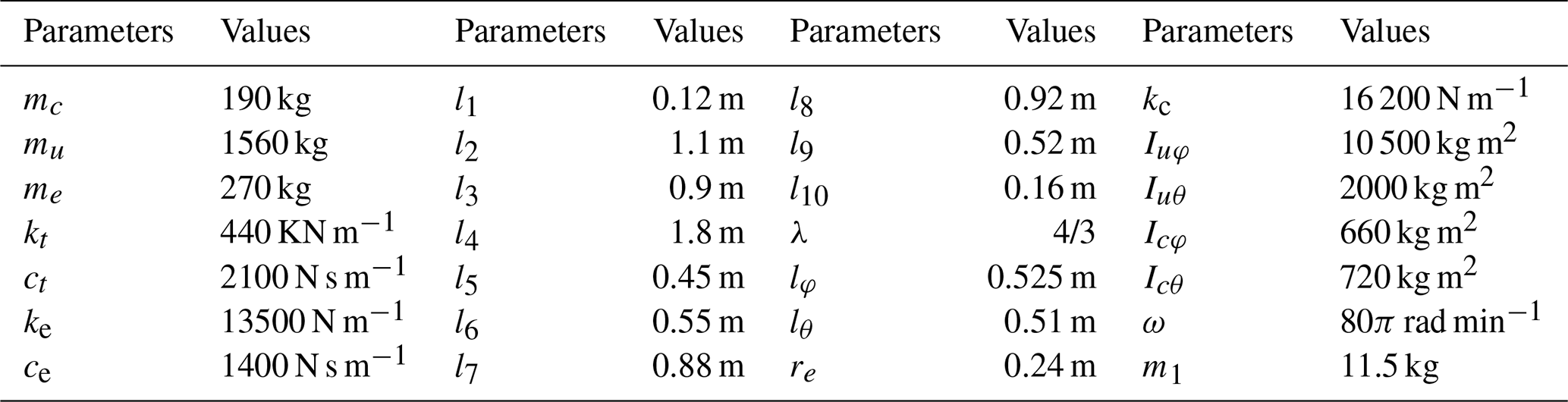
Table 3Simulation parameters and conditions for fuzzy PID, skyhook, and ADRC controllers.
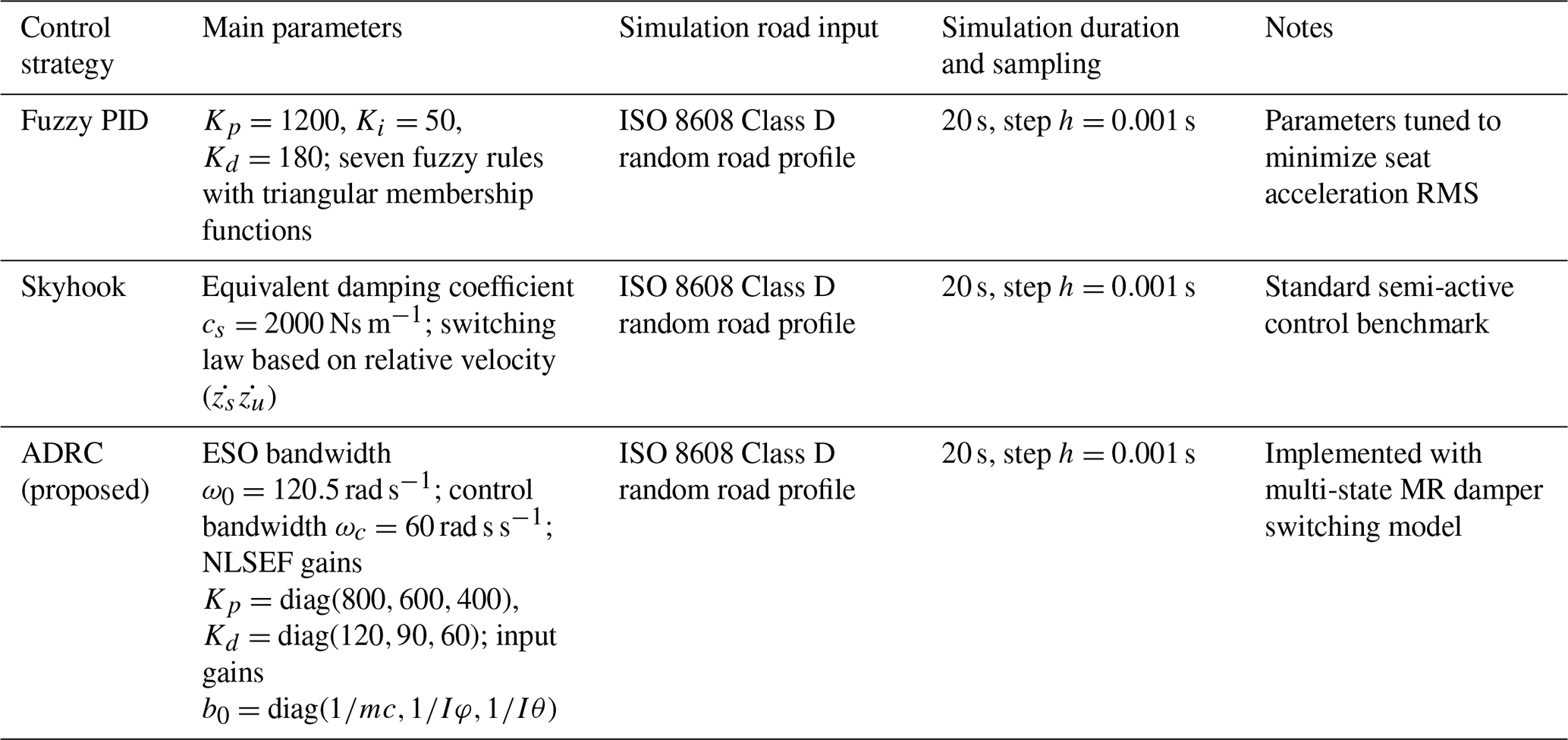
As shown in Table 3, the fuzzy PID controller was tuned to minimize the seat acceleration RMS using a rule base with triangular membership functions, while the skyhook approach employed a fixed equivalent damping coefficient with velocity-based switching logic. In contrast, the proposed ADRC incorporated ESO-based disturbance estimation and nonlinear state error feedback, with explicit parameter values listed to ensure reproducibility. These consistent conditions provide a solid foundation for the subsequent comparison of time- and frequency-domain responses.
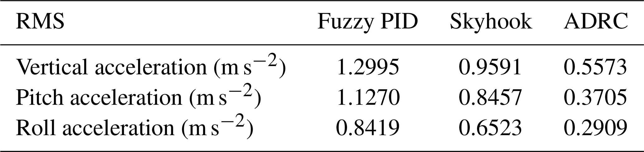
Figures 6–9 present the time-domain responses of the tractor cab suspension system in terms of vertical acceleration, pitch acceleration, roll acceleration, and dynamic suspension travel, respectively. Under the same ISO Class D road profile, the proposed ADRC strategy consistently provides superior vibration attenuation performance compared with both the fuzzy PID and skyhook controllers. A quantitative comparison is given in Table 4. Relative to fuzzy PID control, ADRC reduces the RMS values of vertical, pitch, and roll accelerations by 57.1 %, 67.1 %, and 65.4 %, respectively. Compared with skyhook control, the corresponding reductions are 41.9 %, 56.2 %, and 55.4 %. For dynamic suspension travel, the ADRC-controlled suspension also achieves substantial reductions of 66.8 % and 53.6 % relative to fuzzy PID and skyhook control, respectively. These results demonstrate that the ADRC strategy significantly improves both vibration isolation performance and cab attitude stability under severe broadband excitation conditions. Regarding the dynamic displacement of the cab suspension, the ADRC-controlled system exhibits a significant reduction compared with the fuzzy PID and skyhook methods, with RMS reductions of 66.8 % and 53.6 %, respectively. In addition, the ADRC-controlled suspension system demonstrates superior ride comfort. According to ISO 2631-1, RMS values within 0.315–0.63 indicate slight discomfort, while values below 0.315 correspond to no discomfort (Múčka, 2018). The enhanced impact disturbances on the class D road profile did not degrade the robustness of the tractor cab suspension system under ADRC control. It should be noted that the ADRC-controlled responses exhibit faster vibration suppression and smoother convergence behavior compared with fuzzy PID and skyhook results. This is consistent with the ADRC mechanism, which actively estimates and compensates for disturbances in real time, leading to a distinct response profile. The observed differences in curve shapes therefore reflect the controller's inherent design characteristics rather than inconsistencies in model validation.
Specifically, the curves of the controlled system display the following:
-
reduced peak amplitudes of vibration responses, indicating effective mitigation of sudden shocks transmitted from the chassis;
-
faster decay of vibration oscillations, reflecting improved damping characteristics and enabling quicker return to equilibrium;
-
lower steady-state vibration levels, as evidenced by reduced RMS values (according to ISO 2631 guidelines, a reduction of 20 %–30 % in vertical acceleration RMS corresponds to a measurable improvement in ride comfort classification);
-
consistent pitch and roll suppression, ensuring enhanced cab attitude stability and safer operating conditions;
-
confirmation that the distinct curve shapes observed in the ADRC responses are consistent with theoretical expectations, further validating the effectiveness of the proposed control scheme.
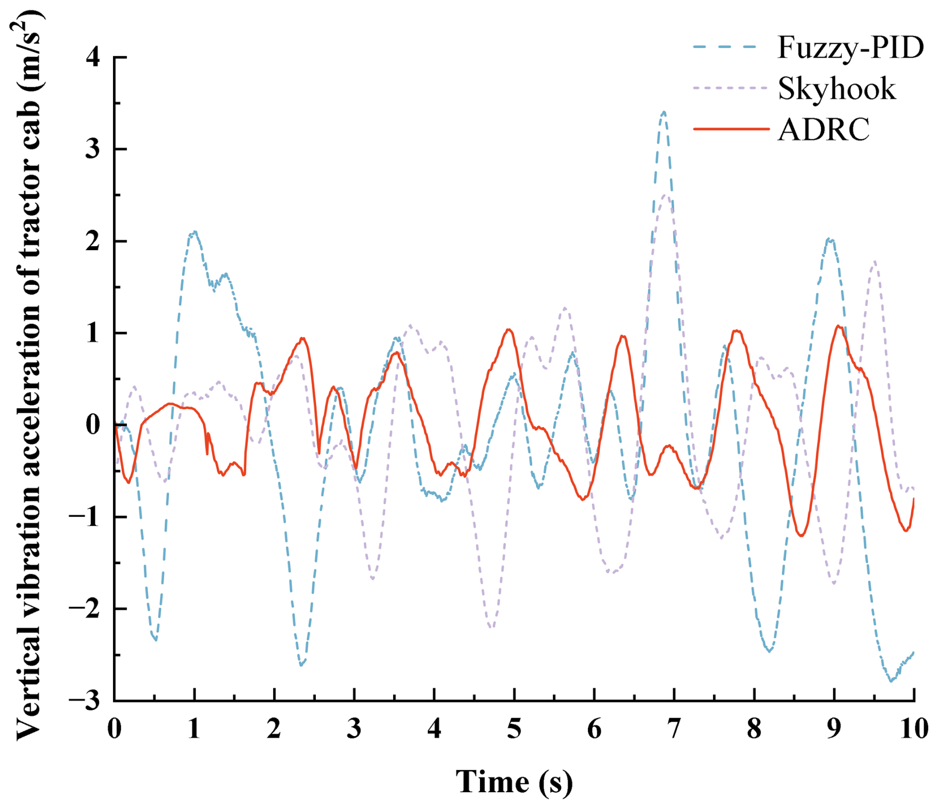
Figure 6Tractor cab vertical acceleration under ISO Class D road excitation at 5 m s−1 for fuzzy PID, skyhook, and ADRC control.
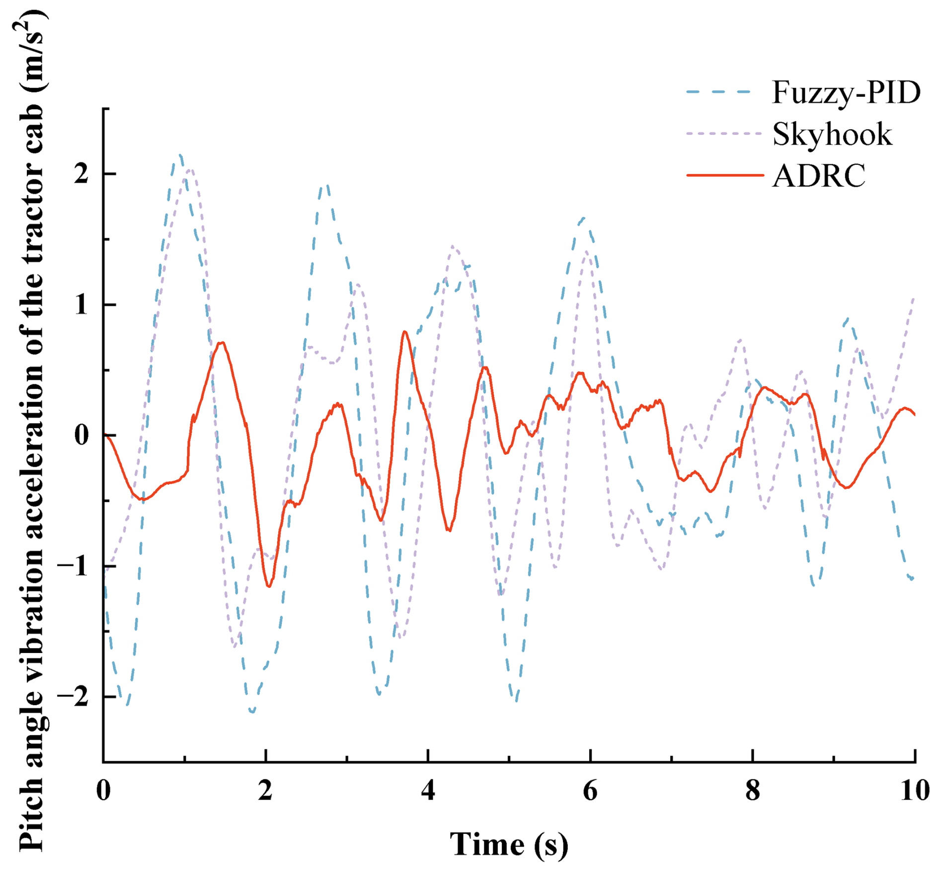
Figure 7Tractor cab pitch acceleration under ISO Class D road excitation at 5 m s−1 for fuzzy PID, skyhook, and ADRC control.
Table 4Comparison of RMS values of different control methods for tractor cab suspension.
It is worth emphasizing that the ISO Class D excitation contains substantial spectral content in the 3–6 Hz band, which coincides with the cab's natural frequencies. Therefore, the performance improvements reported here already demonstrate resonance suppression effectiveness within the broadband input.
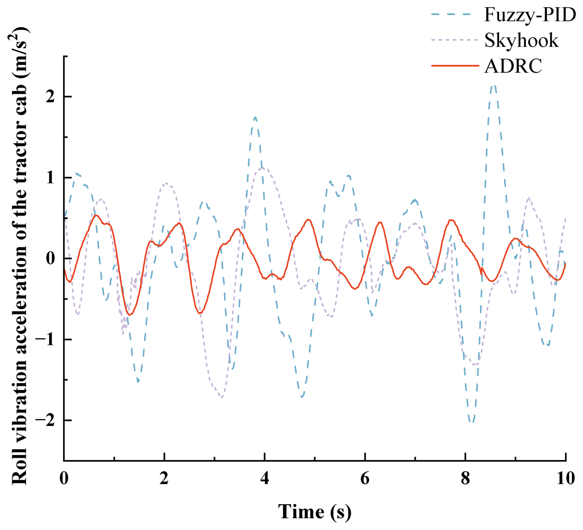
Figure 8Tractor cab roll acceleration under ISO Class D road profiles at 5 m s−1 for fuzzy PID, skyhook, and ADRC control.
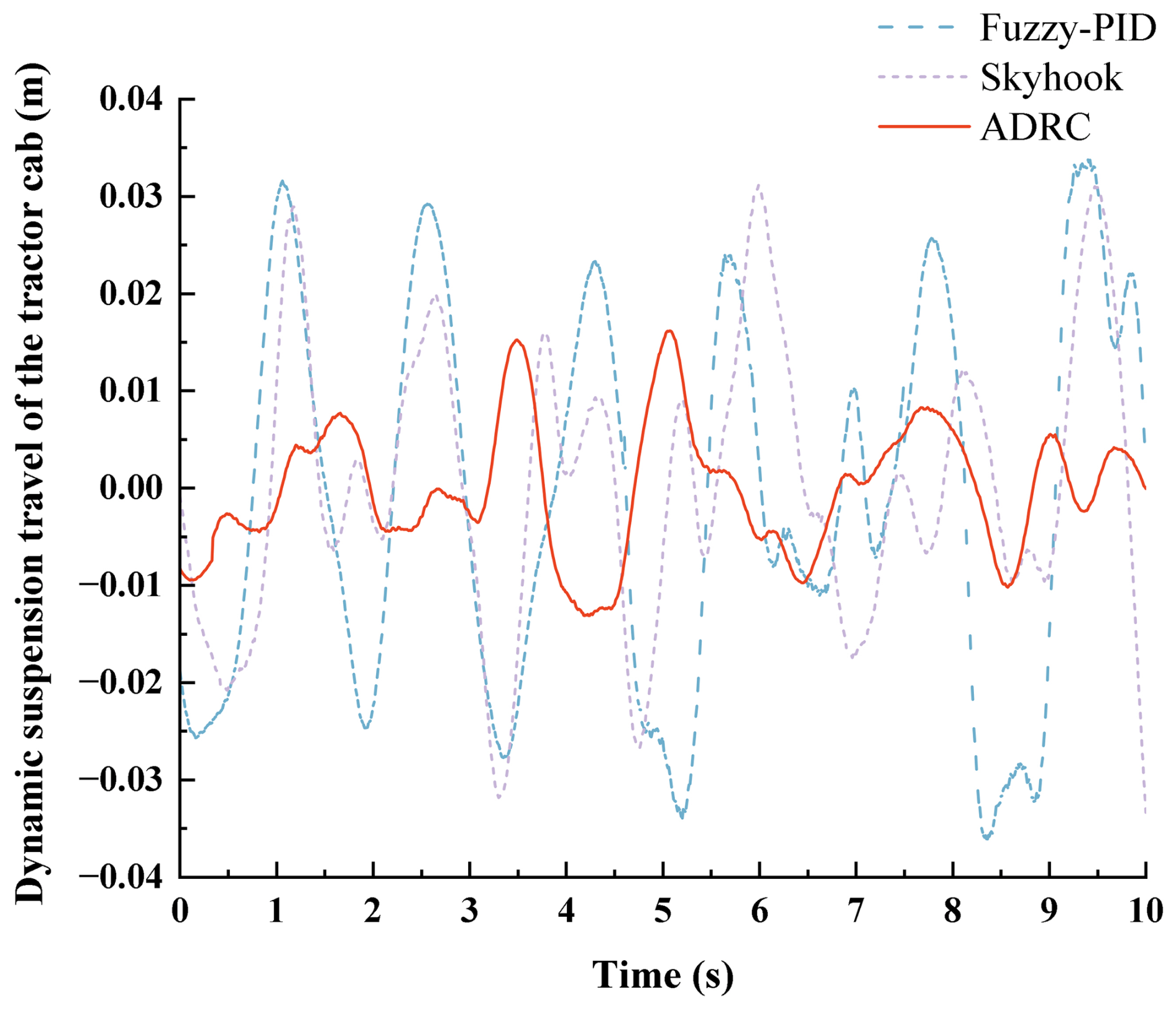
Figure 9Dynamic suspension travel of the tractor cab under ISO Class D road excitation at 5 m s−1 for fuzzy PID, skyhook, and ADRC control.
In addition, to more accurately assess the influence of vibrations with different frequencies and directions on driver comfort, the overall weighted acceleration aw was enhanced and calculated for the three control methods based on the ISO 2631-1 standard. The corresponding formula is given as follows:
where awz, awr, and awp represent the root mean square (RMS) accelerations in the vertical, roll, and pitch directions, respectively. The weighting factors, kz, kr, and kp, correspond to the respective directional components and were selected as kz=1, kr=0.63, and kp=0.4, in accordance with the ISO 2631-1 standard.
The overall weighted accelerations aw, calculated using Eq. (33), are presented in Table 5 for the different control algorithms.
Table 5Overall weighted accelerations under different control algorithms.
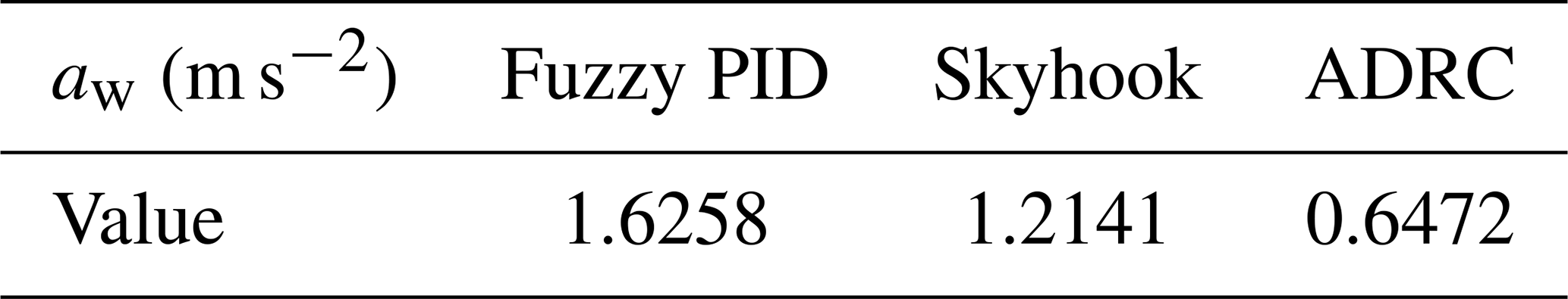
To further interpret the engineering significance of the obtained reductions, the overall weighted acceleration was evaluated according to ISO 2631-1. As shown in Table 5, the ADRC strategy reduces the overall weighted acceleration to 0.6472 m s−2 compared with 1.6258 m s−2 for fuzzy PID and 1.2141 m s−2 for skyhook control. This corresponds to reductions of 60.2 % and 46.7 %, respectively.
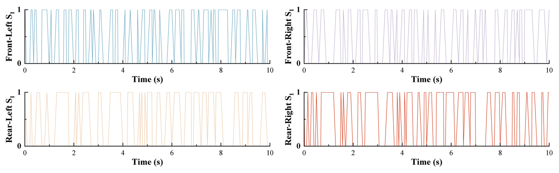
Figure 10Switching states of high-speed hydraulic valve S1 at the four corners of the tractor cab under ADRC-based multi-mode damping control.
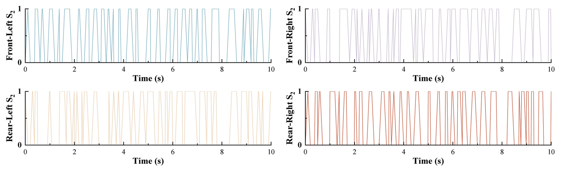
Figure 11Switching states of high-speed hydraulic valve S2 at the four corners of the tractor cab under ADRC-based multi-mode damping control.
From a practical perspective, these reductions indicate that the vibration exposure transmitted to the operator is substantially alleviated. Lower weighted acceleration implies reduced whole-body vibration severity, which is beneficial for improving ride comfort, decreasing fatigue accumulation during prolonged tractor operation, and mitigating vibration-related health risks such as lumbar discomfort and musculoskeletal strain. In particular, the ADRC-controlled response approaches the lower discomfort range defined by ISO 2631-1, whereas the benchmark controllers remain in a more severe vibration exposure region. Therefore, the proposed control strategy is not only effective in a numerical sense, but also meaningful for enhancing operator comfort, reducing fatigue, and supporting safer long-duration field operation.
Figures 10 and 11 illustrate the high-speed switching control signals of solenoid valves S1 and S2 at the four corners of the tractor cab suspension with multi-mode damping switching. As observed from the figures, the ADRC-based damping control strategy enables direct control of the high-speed switching mode of the solenoid valves. Moreover, frequent switching within short intervals is effectively avoided, indicating high system stability.
5.2 Vibration transmissibility analysis
To further evaluate the isolation effectiveness of the suspension system, vibration transmissibility was estimated following the standard definition , where Xc(ω) is the cab response amplitude, and Xu(ω) is the frame/base excitation amplitude. This metric reflects the proportion of vibration transmitted from the tractor frame to the cab structure. Although a full frequency-domain simulation curve is not included here, the transmissibility was estimated at the dominant frequency range (3–6 Hz), corresponding to the cab's natural modes, based on RMS ratios of cab acceleration to chassis excitation. Table 6 summarizes the approximate transmissibility values under different control strategies.
Table 6Estimated vibration transmissibility under different control methods (dominant frequency range 3–6 Hz).

The results indicate that the ADRC-controlled suspension achieves significantly lower transmissibility (below 0.2) across all channels, suggesting superior isolation of vibration energy from the road and engine excitations. This reduction implies that less than 20 % of the base excitation amplitude is transmitted to the cab, whereas conventional controllers allow more than one-third of the excitation to propagate. These findings are consistent with the RMS reduction results presented earlier and further validate the superior vibration suppression capability of the ADRC strategy.
This paper proposes an ADRC-based vibration control strategy for a tractor cab suspension system equipped with a novel multi-state adjustable damper. A detailed 7-DOF dynamic model was established, accounting for the vertical, pitch, and roll motions of the cab, frame, and engine. To address the challenge of nonlinear and uncertain vibration sources – including stochastic road excitations and engine-induced oscillations – an ADRC controller was developed to estimate and suppress total disturbances in real time. A corresponding control allocation method was designed to map ADRC's virtual control forces to discrete damping modes of the four corner dampers via solenoid valve commands. Simulation results under ISO Class D road profile conditions demonstrate the superior performance of the proposed control strategy. Compared with fuzzy PID and skyhook controllers, the ADRC-based approach reduced the RMS values of vertical, pitch, and roll accelerations by 57.1 %, 67.1 %, and 65.4 %, respectively. More importantly, the ISO 2631-1 overall weighted acceleration was reduced to 0.647 m s−2, representing a 60.2 % and 46.7 % improvement relative to fuzzy PID and skyhook, respectively, thereby placing the cab ride comfort into a significantly improved category. The system also demonstrated improved damping stability and effective suppression of suspension travel, demonstrating its strong potential to enhance operator comfort under demanding terrain conditions.
A1 State-space representation
For each motion channel (bounce Zc, pitch ϕc, and roll θc), the cab suspension dynamics can be written in the compact form
where
Here, contains nominal stiffness-related coefficients, represents estimated input gains, and d aggregates unmodeled dynamics and external profiles (road-induced chassis motion and engine vibration forces).
A2 Extended state observer (ESO)
To estimate both the system states and the lumped disturbance, the augmented state vector is defined as
The ESO is formulated as
with , where L is a block-diagonal observer gain matrix. Each channel employs pole placement based on (s+ω0)3, yielding
so that for each channel. The ESO thus reconstructs the total disturbance vector d in real time.
A3 Nonlinear state error feedback (NLSEF)
The tracking errors are defined as , where r is the reference trajectory. A diagonal PD-type feedback law is applied:
where and are feedback gains, and fal(⋅) is a nonlinear function:
The final control input compensates for the ESO-estimated disturbance:
This structure ensures that unmodeled dynamics and external profiles are actively canceled in real time.
A4 Stability consideration
Substituting Eq. (A6) into the closed-loop dynamics yields
If the ESO bandwidth ω0 is sufficiently large, , the error dynamics reduce to
Since KdKp>0, the closed-loop system is asymptotically stable, ensuring robust vibration suppression in the presence of bounded uncertainties and disturbances.
B1 Control allocation matrix
The ADRC controller generates the generalized control vector , corresponding to bounce, pitch, and roll channels. These virtual control forces are mapped to the four corner dampers by
with , and the allocation matrix is defined as
where lx and ly represent half the longitudinal and lateral cab dimensions, respectively. This structure ensures the following:
-
Bounce control (uz) is equally distributed to all dampers.
-
Pitch control (uϕ) produces opposite effects between front and rear dampers.
-
Roll control (uθ) produces opposite effects between left and right dampers.
B2 Mode-switching rules
Each element of ud is continuous, while the physical damper is realized by four discrete modes (soft–soft, soft–hard, hard–soft, hard–hard). To implement the allocation in practice, a threshold-based quantization strategy is applied.
Define four damping modes with equivalent force levels, , and F4}, corresponding to the valve-switching states.
Normalize each damper demand uij to the achievable damping force range.
Select the nearest discrete mode according to
where uij is the implemented mode command for damper ij.
B3 Implementation flow
The complete allocation–switching process is summarized as follows:
-
ADRC generates generalized forces u from bounce, pitch, and roll control loops.
-
These are mapped to corner dampers via Eqs. (B1)–(B2).
-
Each damper demand is discretized into one of the four available modes using Eq. (B3).
-
Final valve commands are issued to achieve the selected damping mode.
This procedure ensures that the continuous ADRC outputs are consistently translated into feasible discrete commands for the multi-state adjustable damper.
All data are given in this paper. No additional datasets were used.
Conceptualization, Z. Liang and B. Chen; methodology, Z. Liang and W. Tao; software, B. Guo and Z. Liang; validation, B. Chen, W. Tao, and Y. Huang; investigation, Z. Liang; data curation, Y. Huang and W. Chen; writing – original draft preparation, Z. Liang and B. Chen.
The contact author has declared that none of the authors has any competing interests.
Publisher's note: Copernicus Publications remains neutral with regard to jurisdictional claims made in the text, published maps, institutional affiliations, or any other geographical representation in this paper. The authors bear the ultimate responsibility for providing appropriate place names. Views expressed in the text are those of the authors and do not necessarily reflect the views of the publisher.
This research was supported by the Natural Science Foundation of Fujian Province (grant nos. 2023J011041 and 2024J01909); the Fujian Provincial Key Science and Technology Project (Key Technologies and Equipment for Continuous and Intelligent Production of Bamboo Scrimber) (grant no. 2024HZ026011); the Nanping Science and Technology Plan Project (grant nos. N2023Z001, N2023Z002, and N2024Z001); the Nature Science Foundation of Nanping, China (grant nos. N2023J001, N2025J001, N2025J002); and the Horizontal Projects of Wuyi University (grant nos. 2024-WHFW-030, 2025-WHFW-043, and 2026-WHFW-003).
This paper was edited by Pengyuan Zhao and reviewed by one anonymous referee.
Atindana, V. A., Xu, X., Nyedeb, A. N., Quaisie, J. K., Nkrumah, J. K., and Assam, S. P.: The evolution of vehicle pneumatic vibration isolation: A systematic review, Shock Vibration, 2023, 1716615, https://doi.org/10.1155/2023/1716615, 2023.
Bai, X., Lu, L., Zhang, C., and Geng, W.: Research on height adjustment characteristics of heavy vehicle active air suspension based on fuzzy control, World Electric Vehicle Journal, 14, 210, https://doi.org/10.3390/wevj14080210, 2023.
Barač, Ž., Plaščak, I., Jurić, T., and Marković, M.: The Impact of Vibrations on the Hand–Arm System and Body of Agricultural Tractor Operators in Relation to Operational Parameters, Approach: Analytical Hierarchical Process (AHP), AgriEngineering, 7, https://doi.org/10.3390/agriengineering7030056, 2025.
Bin, C. and Wei, T.: Wheel loader seat damping control research based on ADRC, Adv. Mech. Eng., 16, 16878132241281277, https://doi.org/10.1177/16878132241281277, 2024.
Cai, Z., An, X., Xie, D., Xue, Y., Liu, X., Wang, Q., Chen, L., Liu, L., Zhang, C., and Xue, C.: An attitude control method with model-aided estimation and parameter-adaptive optimization for high clearance sprayers, Computers Electronics in Agriculture, 237, 110572, https://doi.org/10.1016/j.compag.2025.110572, 2025.
Carreño-Zagarra, J., Moreno, J., and Guzmán, J.: Optimal active disturbance rejection control for second order systems, IEEE Access, 12, 76244-76256, https://doi.org/10.1109/ACCESS.2024.3401079, 2024.
Chen, X., Wang, Z., Shi, H., Jiang, N., Zhao, S., Qiu, Y., and Liu, Q.: Review of Agricultural Machinery Seat Semi-Active Suspension Systems for Ride Comfort, Machines, 13, 246, https://doi.org/10.3390/machines13030246, 2025.
Chen, Y., Shen, S., Li, Z., Hu, Z., and Li, Z.: Semi-Active Suspension Control Strategy Based on Negative Stiffness Characteristics, Mathematics, 12, 3346, https://doi.org/10.3390/math12213346, 2024.
de la Hoz-Torres, M. L., Aguilar, A. J., Martínez-Aires, M. D., and Ruiz, D. P.: A methodology for assessment of long-term exposure to whole-body vibrations in vehicle drivers to propose preventive safety measures, J. Safety Res., 78, 47–58, https://doi.org/10.1016/j.jsr.2021.04.002, 2021.
Diao, S., Zhao, X., Zhao, D., Dong, Z., and Qin, Y.: Hierarchical control of vehicle active suspension system with uncertain sprung mass and time-varying disturbance, P. I. Mech. Eng. D-J. Aut., 09544070251333855, https://doi.org/10.1177/09544070251333855, 2025.
Díaz-Choque, C. S., Félix-Herrán, L., and Ramírez-Mendoza, R. A.: Optimal skyhook and groundhook control for semiactive suspension: A comprehensive methodology, Shock Vibration, 2021, 8084343, https://doi.org/10.1155/2021/8084343, 2021.
Fu, S., Liu, M., Wu, H., Liang, X., and Zeng, X.: Active disturbance rejection control based on BP neural network for suspension system of electromagnetic suspension vehicle, International Journal of Dynamics and Control, 13, 1, https://doi.org/10.1007/s40435-024-01515-3, 2024.
Gao, Z., Yan, H., and Zhou, X.: Active Disturbance Rejection Control of Microgrid DC-DC Converter Based on AC Algorithm, 2024 IEEE International Conference on Mechatronics and Automation (ICMA), 876–881, https://doi.org/10.1109/ICMA61710.2024.10633147, 2024.
Guo, X., Zhang, J., and Sun, W.: Robust saturated fault-tolerant control for active suspension system via partial measurement information, Mechanical Systems Signal Processing, 191, 110116, https://doi.org/10.1016/j.ymssp.2023.110116, 2023.
Herbst, G. and Madonski, R.: Active Disturbance Rejection Control: From Principles to Practice, Springer Nature, https://doi.org/10.1007/978-3-031-72687-3, 2025.
Hu, L., Zhou, C., Wan, Y., and Wang, H.: Research on the Vibration Characteristics of Air Spring Suspension Seats Considering Friction Damping, Appl. Sci., 15, 5817, https://doi.org/10.3390/app15115817, 2025.
Ji, G., Li, S., Feng, G., Li, Z., and Shen, X.: Time-delay compensation control and stability analysis of vehicle semi-active suspension systems, Mechanical Systems Signal Processing, 228, 112414, https://doi.org/10.1016/j.ymssp.2025.112414, 2025.
Jiang, Y., Wang, R., Sun, D., Ding, R., and Yang, L.: Hybrid damping control of magnetorheological semi-active suspension based on feedback linearization Kalman observer, Meccanica, 59, 1087–1102, https://doi.org/10.1007/s11012-024-01827-w, 2024.
Jin, H., Song, J., Lan, W., and Gao, Z.: On the characteristics of ADRC: A PID interpretation, Science China, Information Sciences, 63, 209201, https://doi.org/10.1007/s11432-018-9647-6, 2020.
Lecocq, M., Lantoine, P., Bougard, C., Allègre, J.-M., Bauvineau, L., González, D., Bourdin, C., Marqueste, T., and Dousset, E.: Perceived discomfort and neuromuscular fatigue during long-duration real driving with different car seats, Plos one, 17, e0278131, https://doi.org/10.1371/journal.pone.0278131, 2022.
Li, Q., Chen, Z., Song, H., and Dong, Y.: Finite frequency H∞ control of discrete linear parameter-varying systems, J. Vib. Control, 10775463251325595, https://doi.org/10.1177/10775463251325595, 2025.
Liao, X., Du, X., and Li, S.: Design of cab seat suspension system for construction machinery based on negative stiffness structure, Adv. Mech. Eng., 13, 16878140211044931, https://doi.org/10.1177/16878140211044931, 2021.
Lu, Y., Khajepour, A., Liu, Y., and Zhen, R.: Adaptive cabin suspension systems of commercial vehicles: a review of the state-of-art and future trends, Int. J. Heavy Veh. Syst., 29, 33–47, https://doi.org/10.1504/IJHVS.2022.123242, 2022.
Maciejewski, I., Blazejewski, A., Pecolt, S., and Krzyzynski, T.: A sliding mode control strategy for active horizontal seat suspension under realistic input vibration, J. Vib. Control, 29, 2539–2551, https://doi.org/10.1177/10775463221082716, 2023.
Múčka, P.: Simulated road profiles according to ISO 8608 in vibration analysis, J. Test. Eval., 46, 405–418, https://doi.org/10.1520/JTE20160265, 2018.
Na, J., Huang, Y., Wu, X., Liu, Y.-J., Li, Y., and Li, G.: Active suspension control of quarter-car system with experimental validation, IEEE Transactions on Systems, Man, Cybernetics: Systems, 52, 4714–4726, https://doi.org/10.1109/TSMC.2021.3103807, 2021.
Nguyen, T. A.: Active Disturbance Rejection Control for an automotive suspension system based on parameter tuning using a fuzzy technique, PloS One, 20, e0313104, https://doi.org/10.1371/journal.pone.0313104, 2025.
Ni, S. and Nguyen, V.: Performance of semi-active cab suspension system with different control methods, Journal of Mechatronics Artificial Intelligence in Engineering, 4, 8–17, https://doi.org/10.21595/jmai.2022.23019, 2023.
Schneider, L., Sogemeier, D., Weber, D., and Jaitner, T.: Effects of a seat-integrated mobilization system on long-haul truck drivers motion activity, muscle stiffness and discomfort during a 4.5-h simulated driving task, Appl. Ergon., 106, 103889, https://doi.org/10.1016/j.apergo.2022.103889, 2023.
Shen, Y., Li, J., Huang, R., Yang, X., Chen, J., Chen, L., and Li, M.: Vibration control of vehicle ISD suspension based on the fractional-order SH-GH stragety, Mech. Syst. Signal Pr., 234, 112880, https://doi.org/10.1016/j.ymssp.2025.113740, 2025.
Shen, Y., Ren, H., and Sara, Y.: Vehicle semi-active air ISD suspension with frequency-varying negative stiffness: design, control, and experimental validation, Mech. Syst. Signal Pr., 244, 113740, https://doi.org/10.1016/j.ymssp.2025.112880, 2026.
Soliman, A. and Kaldas, M.: Semi-active suspension systems from research to mass-market–A review, J. Low Freq. Noise V. A., 40, 1005-1023, https://doi.org/10.1177/1461348419876392, 2021.
Sun, Q., Yin, C., and Wang, B.: The application of neural networks driven by nonlinear model data in road roughness estimation, Meas. Sci. Technol., 36, 026004, https://doi.org/10.1088/1361-6501/ad9855, 2024.
Tao, W. and Liu, Z.: Variable universe fuzzy control of the wheel loader semi-active cab suspension with multimode switching shock absorber, T. Can. Soc. Mech. Eng., 45, 548–561, 2021.
Tao, W., Chen, B., Zhou, L., Zheng, Z., Wu, J., and Duan, M.: Design of a magnetorheological (MR) suspension damper for an agricultural tractor seat based on an adaptive neuro-fuzzy inference system (ANFIS) and active disturbance rejection control (ADRC), Mech. Sci., 16, 113–124, https://doi.org/10.5194/ms-16-113-2025, 2025.
Wang, H., Wang, Z., and Long, Z.: A Modified ADRC Scheme Based on Model Information for Maglev Train, Actuators, 13, 328, https://doi.org/10.3390/act13090328, 2024.
Wos, P. and Dziopa, Z.: Study of the Vibration Isolation Properties of a Pneumatic Suspension System for the Seat of a Working Machine with Adjustable Stiffness, Appl. Sci., 14, https://doi.org/10.3390/app14146318, 2024.
Yang, X., Shen, Y., Liu, C., and Zhang, T.: Design and Performance Analysis of HMDV Dynamic Inertial Suspension Based on Active Disturbance Rejection Control, CMES-Comp. Model. Eng., 140, https://doi.org/10.32604/cmes.2024.049837, 2024.
Yang, X., Sun, R., Yang, Y., Liu, Y., Hong, J., and Liu, C.: Enhanced Seat Suspension Performance Through Positive Real Network Optimization and Skyhook Inertial Control, Machines, 13, 222, https://doi.org/10.3390/machines13030222, 2025.
Yu, C., Yao, J., Jiao, S., and Li, D.: Design and verification of a magnetorheological elastomer-based vibration isolator with adjustable stiffness, Structures, 108762, https://doi.org/10.1016/j.istruc.2025.108762, 2025.
Yu-Hao, T., Rui-Feng, W., and Wen-Hao, S.: Active disturbance rejection control – New trends in agricultural cybernetics in the future: A comprehensive review, Machines, 13, 111, https://doi.org/10.3390/machines13020111, 2025.
Zhang, N., Zhao, Q., and Huang, S.: Optimal sliding mode hierarchical decoupled control of vehicle semi-active suspension, Vehicle Syst. Dyn., 1–31, https://doi.org/10.1080/00423114.2024.2398750, 2024.
Zhang, S., Ren, W., Xie, B., Luo, Z., Wen, C., Chen, Z., Zhu, Z., and Li, T.: A combined control method of traction and ballast for an electric tractor in ploughing based on load transfer, Computers Electronics in Agriculture, 207, 107750, https://doi.org/10.1016/j.compag.2023.107750, 2023.
- Abstract
- Introduction
- Materials and methods
- Analysis of the tractor cab suspension system
- Design of a damping control strategy for the tractor cabin suspension system
- Simulation and analysis
- Conclusions
- Appendix A: Detailed ADRC formulation
- Appendix B: Control allocation and mode switching
- Data availability
- Author contributions
- Competing interests
- Disclaimer
- Financial support
- Review statement
- References