the Creative Commons Attribution 4.0 License.
the Creative Commons Attribution 4.0 License.
 | 18 Nov 2025
A continuum-based model for a layer jamming beam
Shuai Zhang
Jiantao Yao
Wumian Zhao
Chunjie Wei
Layer jamming structures (LJSs) are widely used as variable-stiffness components in collaborative robots to ensure safe human–robot interaction. However, existing analytical models often fail to adequately describe the mechanical behavior of LJSs with a large number of layers, particularly in capturing detailed stress distributions and deformations. This paper introduces a continuum-based layer jamming model (CLJM), which treats the LJS as a continuous medium under the assumption of infinitely many thin layers. The CLJM comprehensively analyzes internal stress distribution – including both shear and normal stresses – and deformation across different mechanical states (full jamming, half slipping, and full slipping). The model is validated through finite-element analysis (FEA) and experimental tests, showing strong agreement in both deformation response and stress profiles. The results demonstrate that the CLJM provides an effective and accurate theoretical tool for designing LJSs in variable-stiffness applications.
- Article
(4452 KB) - Full-text XML
- BibTeX
- EndNote


For many structures, stiffness – an essential mechanical characteristic – remains constant during operation. However, as machines increasingly operate in unstructured environments, variable-stiffness structures are more effective than constant-stiffness ones in interacting with non-cooperative targets (Morrison and Su, 2020). The pursuit of variable stiffness is a pervasive theme in modern mechanical and robotic design, extending beyond layer jamming to include innovative mechanisms in various applications. For instance, in vehicle suspension systems, Anubi et al. (2013) demonstrated a passive variable-stiffness suspension that outperforms constant-stiffness designs by optimally controlling energy dissipation, highlighting the broad performance benefits of adaptive stiffness. In the realm of robotic joints, Yigit and Boyraz (2017) designed a cable-driven parallel-series hybrid variable-stiffness joint, addressing critical needs for compliance and workspace adaptability in humanoid robotics through a sophisticated mechanism incorporating elastic elements. These diverse approaches underscore the field's active exploration of variable-stiffness principles. Among various variable-stiffness techniques, jamming structures have garnered significant attention from researchers and engineers and have been applied in numerous fields (Blanc et al., 2017; Caruso et al., 2022a).
Jamming refers to the physical process in which discrete particles, layers, or fibers confined within a limited volume transition from liquid-like to solid-like behavior under increased stress (Brancadoro et al., 2020; Liu and Nagel, 1998). As a variable-stiffness technique, layer jamming beams offer features such as rapid and reversible transitions between different stiffness states and ease of fabrication (Blanc et al., 2017; Caruso et al., 2022a). Kawamura et al. (2002, 2003) and Tabata et al. (2000) were the first to introduce layer jamming structures (LJSs) into the engineering field as a variable impedance mechanism for wearable devices. Subsequently, LJSs have been employed in diverse applications, including medical endoscopic robots (Kim et al., 2012, 2013), soft actuators (Wall et al., 2015), grippers (Elgeneidy et al., 2019; Hou et al., 2019; Zhu et al., 2019), and cooperative robot arms (Zhou et al., 2020).
To further expand the engineering applications of LJSs, their mechanical behavior must be well understood to guide the design process. This area has been the focus of several studies. However, due to the complex interactions within jamming structures, effective numerical or analytical methods for modeling these structures are still needed. Specifically for LJSs, a widely accepted model focuses on the second moment of the cross-section, yielding for a solid-like state and for a liquid-like state (Henke and Gerlach, 2014; Ibrahimi et al., 2021; Kawamura et al., 2002), where n is the number of layers, δ is the thickness of the layers, and b is the width of the layers. Narang and colleagues (Narang, 2018; Narang et al., 2018a, b, 2020) were the first to present a comprehensive model of two-layer jamming cantilevers using Euler–Bernoulli beam theory. Their model not only predicts the stiffness of LJSs but also provides transition criteria, and it has been extended to multi-layer beams using finite-element methods. Furthermore, Caruso et al. (2022b) developed a model for multi-layer jamming cantilevers based on stress analysis, resulting in a summation form. They also introduced an analytical model to describe the three-point bending of multi-layer jamming beams (Caruso et al., 2022a, 2023). LJS beams bear similarity to composite beams with interlayer slip. Newmark (1951) studied composite beams with incomplete interaction, while Schnabl et al. (2007) provided an analytical solution for two-layer beams with interlayer slip and shear deformation. Tarsi and Afshin (2022) studied the delamination propagation in composite beams. However, these studies cannot adequately describe the deformation behavior of LJSs with significant slip.
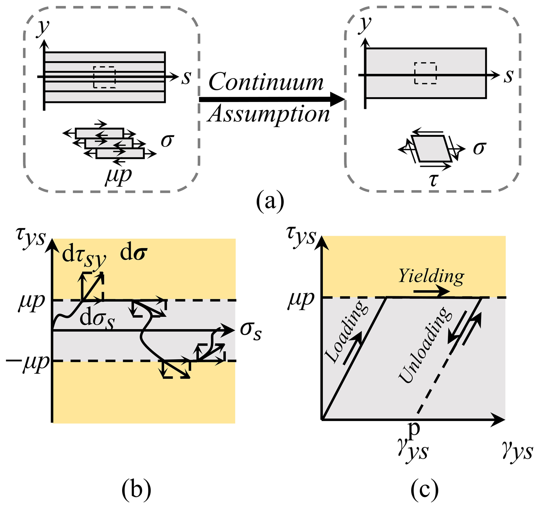
Figure 1Continuum-based layer jamming model. (a) LJM based on continuum assumption. (b) The stress state and its deforming path in the τ–σ stress space of the CLJM. (c) The elastoplastic deformation process of the LJM.
The analytical models of LJSs proposed in previous research often lack sufficient detail in stress distribution and model multi-layer mechanical behavior on a layer-by-layer basis. This approach becomes impractical when the number of layers is large. When a sufficient number of thin layers is present, it is unnecessary to distinguish between individual layers, and LJSs can be treated as a continuum. The continuum assumption is rigorously justified when the number of layers is sufficiently large, rendering the discrete effects negligible. This approach is analogous to methods employed in modeling laminated composites or granular materials, where the macroscopic behavior emerges from the collective interaction of a large number of constituents. In this work, we focus on the regime where the layer thickness δ is much smaller than the beam height h (i.e., ), which means the number of layers n is large, ensuring the validity of treating stress and strain as continuous fields across the beam's height.
This paper is organized as follows. Section 2 introduces the basic concept and properties of the continuum-based layer jamming model (CLJM). Section 3 provides a detailed analysis of the internal forces and stresses in LJSs. Section 4 describes the deformation behavior of LJSs. Section 5 compares the CLJM results with experimental and FEA data. Finally, Sect. 6 presents the conclusions.
The transition from a discrete layered system to a continuum is grounded in the limit where the layer thickness δ approaches zero, while the total height h remains constant, equivalent to an infinite number of layers. Under this assumption, which holds effectively for layers in practical applications, as shown in the FEA comparison (Sect. 5), mechanical quantities such as stress and strain become continuous functions of the spatial coordinate y. When the sheet is exceptionally thin, the layer jamming structure (LJS) can be considered to be a beam composed of a special type of continuous medium, based on the assumption that the layer thickness approaches zero, while the number of layers becomes infinite. In this case, all physical quantities can be treated as continuous functions along the beam height, enabling the use of continuum mechanics in the modeling process. The mechanical behavior of the LJS is described in this section using fundamental concepts from continuum mechanics.
From a continuous media perspective, the LJS may be modeled as a curved beam with a rectangular cross-section. To facilitate the description, the coordinate system in Fig. 1a is introduced: the s axis represents the central surface of the beam, the y axis represents the beam height, and θ is the angle between the y axis at s and at s=0. The radius of the curvature at s is . To illustrate the relationship between the LJS and continuum mechanics, the stress state of the differential volume element at (s, y) in Fig. 1a is analyzed.
Similarly, Euler–Bernoulli beam theory assumes that all material points in the beam are in a plane stress state, neglecting interlaminar normal strain. Under this assumption, the stress state at (s, y) can be fully described by σ and τ, where σ represents the tensile force within a sheet, and τ represents the friction between sheets. The complete stress state can be represented as a point in the τ–σ diagram, as shown in Fig. 1b. Under an applied load, the differential volume element at (s, y) deforms, as illustrated in Fig. 1a. This deformation is characterized by normal strain εs and shear strain γsy. It should be noted that εs arises from the extension of sheets, while γsy is caused by both the extension of sheets and the slippage between them.
From the perspective of continuous media, LJSs can be viewed as curved beams made of specific elastoplastic materials, and their similarities are discussed later. Since interlayer normal strain is neglected, no elastic deformation-induced pressure exists between sheets. Consequently, the maximum static friction per unit area between sheets is given by μp, where p is the vacuum pressure acting on the LJS, and μ is the friction coefficient between layers. When , there is no slipping between sheets, only extension, and this stress state is referred to as the jamming state. Conversely, when , slip occurs, and the stress state is referred to as the slipping state. In the τ–σ diagram, the jamming state region appears as a gray strip around the σ axis, while the slipping state region is represented by two yellow strips above and below. Deformation in the jamming state is entirely reversible upon unloading, indicating elastic behavior. However, sliding in the slipping state is irreversible and can be regarded as plastic deformation. The stress state (σ, τ) exists only on the boundary or within the jamming state region.
The elastoplastic deformation behavior of the LJS medium is illustrated in Fig. 1c and can be divided into three stages: loading, yielding, and unloading. Each stage follows distinct principles, necessitating clear criteria for stage differentiation. These criteria, as illustrated in Fig. 1b, are as follows:
It is important to note that shear strain is independent of shear stress and can take any value in the yielding stage. Aside from that, there is no one–one mapping between shear strain and shear stress. All of this suggests that the deformation of the LJS medium must be solved incrementally.
3.1 Internal force analysis
From the perspective of the continuum, the mechanical behavior of LJS beams can be studied by utilizing the equivalent concentrated internal force on a section, that is, the axial force N, shear force Q, and bending moment M, as in Euler–Bernoulli beam theory.
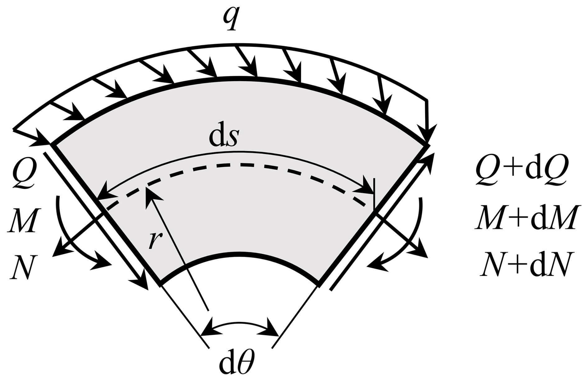
By concentrating on the differential beam segment ds in Fig. 2, the relationship between internal force and the loads on LJM beams is explored. As shown in Fig. 2, the center angle corresponding to ds is dθ, and the radius of curvature of the axis s is r. N and N+ dN are the axial forces on the left- and right-end sections, Q and Q+ dQ are the shear forces on the left- and right-end sections, and M and M+ dM are the bending moments on the left- and right-end sections of the differential beam segment, respectively. q is the distributed load on the curved beam. The arrows in Fig. 2 indicate the positive direction of each mechanical quantity. By ignoring the second-order small quantities and considering the approximation of cos dθ≈1 and sin dθ≈ dθ, the force and moment balance equations on the left-end section can be expressed as follows:
where qs and qy represent the components of q along the s and y axes, respectively. The first two equations of Eq. (1) can give the solution written as
where N0 and Q0 are the internal forces at s0 that can be obtained by solving the LJS beams' reaction force. Following that, M(s) can be calculated by integrating from Q(s).
It should be noted that the conclusion of this section holds for the region of both jamming and slipping LJS beams since its deduction depends only on the continuum assumption.
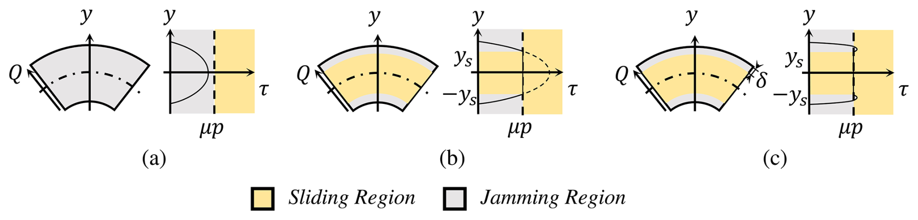
Figure 3The section deformation state of the LJM beam. (a) Full-jamming state. (b) Half-slipping state. (c) Full-slipping state.
3.2 Stress analysis
Next, we focus on the shear stress in LJS beams. It is evident that when the shear force Q on a section is sufficiently small, there will be no sliding region, and the section is considered to be in the full-jamming state, which is shown in Fig. 3a. For a section in the full-jamming state, the shear stress distribution of a rectangular straight beam can approximate that of a curved beam because the radius of curvature r of LJS beams is much larger than their height h. This implies that for a section with a free surface, the following equation holds:
where A is the area of the rectangular cross-section, A=bh, and b is the width of the beam.
As Q on a section increases, the central region of the section transitions from the jamming state to the slipping state because τ follows a quadratic distribution along the y axis. Such a section is referred to as being in the half-slipping state, as shown in Fig. 3b. However, in general, sections with a free surface in an LJS beam cannot transition entirely into the slipping state. This is because the outermost layers will always remain in the elastic (jamming) state. As Q continues to increase, the limiting case is reached when no jamming region remains for – δ, where δ is the thickness of a single layer. This state is referred to as the full-slipping state, as depicted in Fig. 3c.
The distribution of τsy on a section in the half-slipping state can then be derived. Within the jamming region, τ follows a form similar to Eq. (3), but Q is replaced by Qeq, which is determined by solving τ(ys, Qeq)=μp, where ys is the boundary between the jamming and sliding regions. The result is
The distribution of τ in the jamming region can then be obtained by substituting Q in Eq. (3) with Qeq as given in Eq. (4).
The critical shear force Qslip, which represents the threshold between the full-jamming and half-slipping states, can be determined by solving maxy [τ(y, Q)] =μp. From Eq. (3), it is evident that τ reaches its maximum value at y=0. When the section transitions from the half-slipping state to the full-slipping state, the boundary ys satisfies . In this case, substituting Q in Eq. (3) with Qeq in Eq. (4) and integrating τ across the section yield another critical shear force, Qmax:
These expressions are derived based on the fact that τ equals sign(Q)μp in the sliding region .
To summarize, the shear stress τ(y, s) in an LJS beam can be expressed as follows:
Here, the coefficients c0, c1, and c2 can be determined by the following conditions: , τ(ys, s)= sign(Q)μp, and . The resulting expressions for c0, c1, and c2 are as follows:
Finally, the most critical parameter, ys, can be obtained by solving . Setting ys=0 in the full-jamming state and in the full-slipping state, ys can then be expressed as
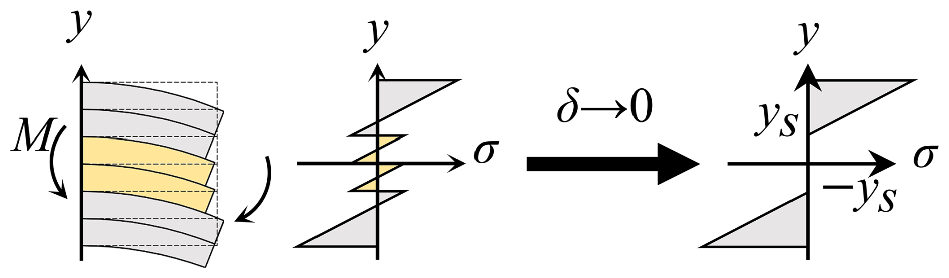
Next, we turn to the distribution of normal stress in LJS beams. The distribution of normal stress σ varies depending on the deformation state. For the full-jamming state, σ distribution is equivalent to that of an elastic beam. In the jamming regions of the half-slipping and full-slipping states, the normal stress follows a linear distribution for reasons previously discussed. Considering an LJS beam subject to a bending moment only, each layer can be treated as a beam. Consequently, the function σ(s, y) in the sliding region can be represented as a series of polylines, as shown in Fig. 4. The amplitude of these polylines decreases to zero as the layer thickness approaches zero, indicating an infinite number of layers. Combining these observations, the normal stress distribution can be expressed as
Here, the subscript J denotes quantities defined in the jamming region; that is, NJ represents the axial force in the jamming region, AJ is the cross-sectional area of the jamming region (), and KJ is a proportional coefficient. In addition, the symbol ∓ in Eq. (10) takes the minus sign when y≥ys and the plus when . σS denotes the normal stress distributing on the sliding regions, which is discussed in detail later.
The relationships between NJ, MJ (for momentum on the jamming region) and N, M are
where σS denotes the normal stress in sliding regions. And MJ can be determined by integrating Eq. (10) over the jamming region:
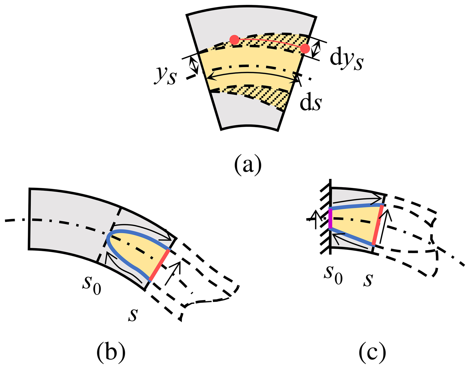
Figure 5The normal stress analysis in the sliding region. (a) The normal stress distribution in the sliding region. (b) Neither of the sliding region's end sections is in the half-slipping state. (c) At least one of the end sections is in the half-slipping state.
To determine the distribution of σS in the sliding region, we apply the differential equation of stress balance:
Since τS in the sliding region is a constant sign (Q)μp, we have . Solving Eq. (13) yields σS=f(y), where f is an unknown function, indicating that σS depends only on s in the sliding regions. This implies that σS takes the same value at all points with the same y in the sliding region (e.g., all points on the red line in Fig. 5a). Consequently, σS(y) dy=σS(ys) dys and σS(y)y dy=σS(ys)ys dys.
Using this property and the relation dys=ys′ ds, the integrals over y in Eq. (11) can be transformed to integrals over s for sections in the half-slipping state. There are two cases. (1) Neither end of the sliding region is in the half-slipping state, as shown in Fig. 5b. (2) At least one end of the sliding region is in the half-slipping state, as shown in Fig. 5c. For the first case, the original integral over y (domain indicated by the red line in Fig. 5b) can be divided into two integrals over s (domain indicated by the blue curves), as mathematically described:
where s0 is one end of the half-slipping state segment.
Based on the continuum assumption, the normal stress should remain continuous across the boundary, which means that there are σS(ys)=σJ(ys) and . Substituting Eqs. (14) and (10) into Eq. (11) and noticing can give
The derivative of Eq. (15) gives the differential equation about NJ:
Considering that at s0 there is NJ=N, the solution of Eq. (16) is
For the second case, the original integral over y, whose domain is indicated by the red line in Fig. 5c, can be divided into three parts: two integrals over s, whose domain is indicated by the blue curves, and an integral over y, whose domain is indicated by the purple line. Applying the same transformation technique used in Eq. (14), we can obtain a differential equation that is the same as Eq. (15), and it can also give a similar solution to the first case, but the values of NJ at s0 should correspond to the distribution of σJ at s0. Supposing that the axial force at s0 is evenly distributed on the section gives the normal stress distribution at s0:
where KJ is solved by combining Eqs. (12) and (15). It is then easy to compute that NJ(s0)=N(s0)2ys .
The goal of the deformation analysis is to obtain Δθ(s) under a given load q. Using q and θ(s), the internal forces can be obtained from Eq. (2). Notably, the deformation of an LJS beam derived from the jamming region and sliding region is consistent. This consistency allows the deformation of an LJS beam to be calculated solely based on the internal moment within the jamming region.
For small deformations of an LJS beam, the following relationship holds in the jamming region, based on Euler–Bernoulli beam theory:
where IJ represents the moment of inertia of the jamming region in LJS beams. Its value can be calculated as follows:
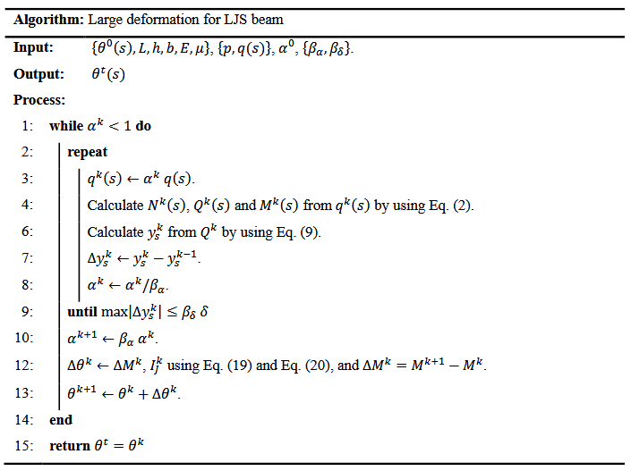
The mechanical response of the LJS beam under a large load q must be solved incrementally, based on the small deformation assumption. A detailed algorithm for this step-by-step procedure is presented in the Algorithm.
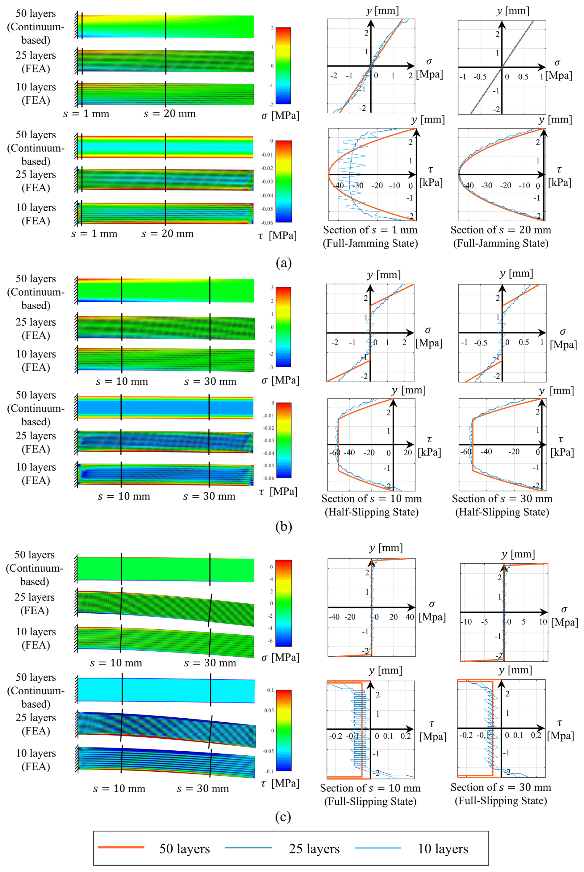
Figure 6FEA analysis of straight LJM cantilever's stress distribution. (a) Distribution of σ and τ under 3N load. (b) Distribution of σ and τ under 4N load. (c) Distribution of σ and τ under 5.5N load.
To further validate the mechanical behavior predicted by the proposed method, stress distributions obtained using finite-element analysis (FEA) provide a more detailed comparison. The LJS cantilevers analyzed in FEA measure 40 mm in length, 20 mm in thickness, and 5 mm in height. These cantilevers consist of 10 and 25 layers, with assumed material parameters of a friction coefficient μ=0.5 and Young's modulus E=0.3 GPa. The finite-element models were constructed in Abaqus, utilizing CPS4R elements with a side length of 0.1 mm. A pressure of 0.1 MPa was applied on the upper and lower surfaces, and a concentrated force was evenly distributed along the free ends of each layer to facilitate convergence.
The shear and normal stress distributions predicted by the continuum-based model and FEA are shown in Fig. 6. For full-jamming sections, Fig. 6a illustrates the stress distribution at s=30 mm under a 3N load. Here, the stress distributions predicted by FEA and the continuum-based model align closely, supporting the assumption that the jamming region behaves like an elastic material. However, near the ends of the cantilever, such as at s=1 mm under a 3N load, the shear stress distribution changes significantly depending on the number of layers. As the number of layers increases, the amplitude of τ(y) predicted by FEA decreases and becomes more continuous, though it deviates from the parabolic shape due to boundary effects.
For half-slipping sections, Fig. 6b shows the stress distribution at s=10, s=10, and s=30 mm. In the middle segments of the cantilever, the stress distributions predicted by FEA and the continuum-based model show minimal differences. However, the sliding region predicted by FEA is narrower than that predicted by the continuum-based layer jamming model (CLJM). This discrepancy arises from the CLJM's neglect of normal stress along the y axis. Ignoring this stress leads to an overestimation of the sliding region, as the normal stress along the y axis can raise the critical shear stress, reducing the extent of sliding. Consequently, the slope of the normal stress in the jamming region predicted by FEA is smaller than that predicted by CLJM.
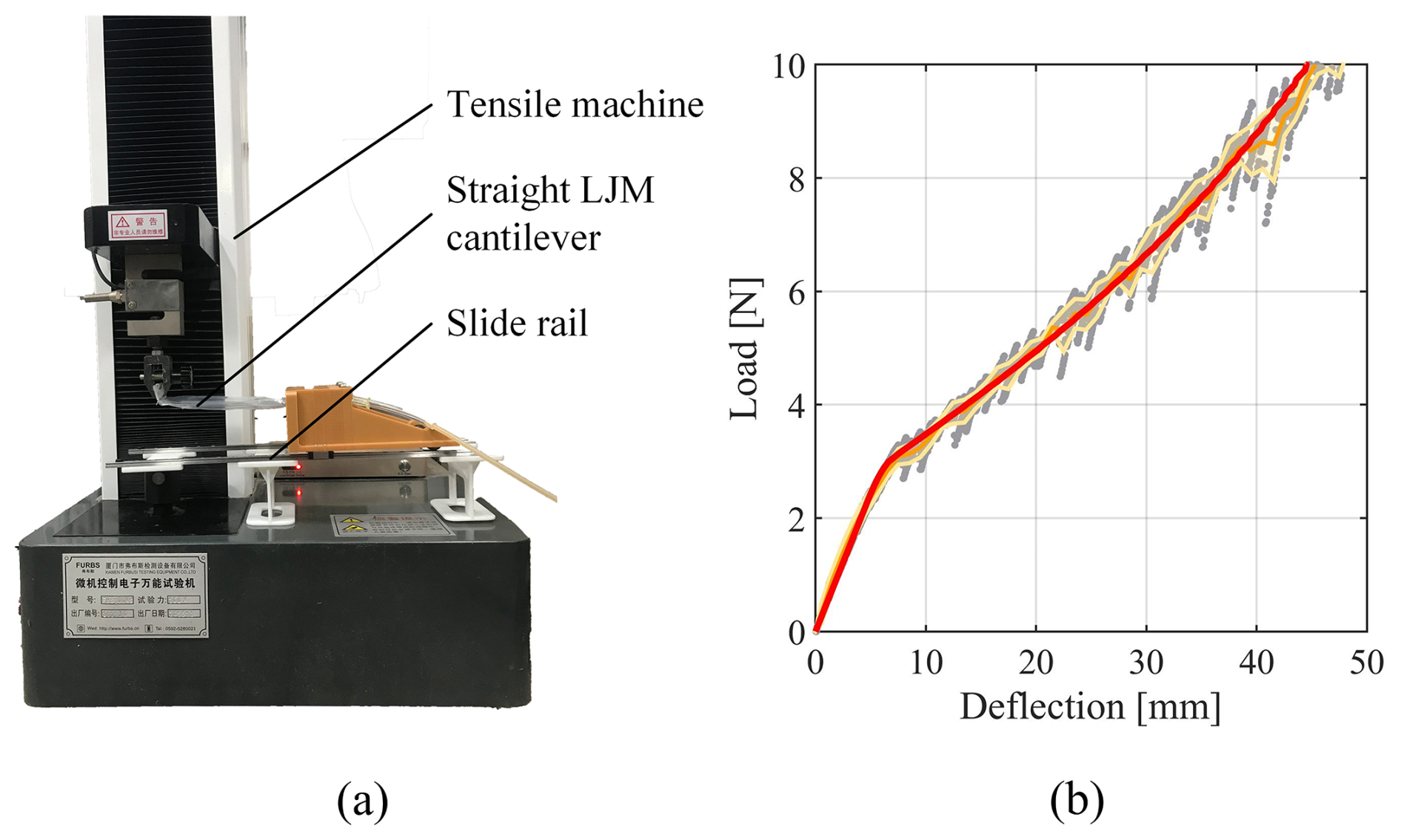
Figure 7Experimental analysis of straight LJM cantilever's deformation. (a) The measuring device. (b) Experimental result.
For full-slipping sections, Fig. 6c highlights the differences in stress distributions. Similar to the half-slipping sections, the sliding region predicted by FEA is narrower than that predicted by CLJM, and the shear stress in the sliding region obtained by FEA fluctuates around the values predicted by CLJM. However, a significant discrepancy exists in the jamming region's shear stress between FEA and CLJM. This error likely occurs because LJS beam segments in the full-slipping state behave more like curved beams, while CLJM assumes that the shear stress distribution in the jamming region follows the pattern of elastic straight beams, introducing notable inaccuracies.
The relationship between load and deflection in a straight LJS cantilever can be easily measured using a tensile machine. The experimental setup used in this study is shown in Fig. 7a. In this setup, the straight LJS cantilever is fixed to a frame that slides freely along a rail to eliminate horizontal restraints. A flexible PVC membrane encasing 20 PVC sheets forms the test specimen, which measures 100 mm in length, 20 mm in thickness, and 5 mm in height.
The load-deflection results under 60 kPa pressure are represented as gray dots in Fig. 7b. The orange curve denotes the experimental mean, while the error bars spanning ±1 standard deviation are shown as the yellow-shaded area. The analytical results, depicted by the red curve in Fig. 7b, were obtained using the previously discussed algorithm and the material parameters: Young's modulus E=755 MPa and friction coefficient μ=0.55. The analytical curve lies entirely within the 1σ interval, demonstrating the validity of the proposed analysis method for describing the mechanical behavior of the LJS cantilever.
These discrepancies, particularly near the boundaries and in the full-slipping state, highlight the inherent limitations of the current continuum assumption, which does not explicitly account for end effects or the curved beam behavior under large slip. Nevertheless, the proposed CLJM demonstrates high accuracy in predicting global deformation and stress distribution in the central regions of the beam under small-to-moderate slip conditions, which are of primary interest in most practical applications. Future refinements could incorporate boundary correction factors or a more detailed treatment of curvature in the jamming region.
In this study, an analytical model based on continuum mechanics is presented to describe the mechanical behavior of LJS beams. Previous works typically treated each layer in the LJS beam as an independent beam, which is inadequate for handling LJSs with numerous layers and describing stress distribution in detail. In contrast, the continuum layer jamming model presented here treats the LJS as a continuous medium, assuming that all mechanical quantities are continuous across the material. This model enables the description of various mechanical behaviors of the LJS beam, such as stress distribution, deformation, and other related phenomena. The effectiveness of CLJM is validated through experiments and FEA. The deformation predicted by CLJM aligns well with experimental measurements, and the stress distribution predicted by CLJM closely matches the results obtained from FEA. Ultimately, it can be concluded that the assumption of treating LJSs as a continuum is reasonable, providing engineers with a valuable tool for designing materials to meet the specific demands of various engineering applications.
The CLJM provides a robust analytical foundation for designing LJSs with a large number of layers. It is most accurate for predicting global mechanical behavior away from constraint boundaries and under partial-slip conditions. The model's simplicity and computational efficiency make it particularly suitable for preliminary design and optimization, while FEA remains recommended for final verification, especially near free ends or under extreme loading leading to full slipping.
No data were generated or used in the preparation of this paper.
SZ and JY conceived and supervised the study. WZ carried out the numerical analysis, and CW conducted the experimental investigation. SZ performed the formal analysis and wrote the paper draft, and JY reviewed and edited the paper.
The contact author has declared that none of the authors has any competing interests.
Publisher’s note: Copernicus Publications remains neutral with regard to jurisdictional claims made in the text, published maps, institutional affiliations, or any other geographical representation in this paper. While Copernicus Publications makes every effort to include appropriate place names, the final responsibility lies with the authors. Views expressed in the text are those of the authors and do not necessarily reflect the views of the publisher.
The authors thank the reviewers for their critical and constructive review of the paper.
This research has been supported by the National Natural Science Foundation of China (grant no. 52375030) and the Natural Science Foundation of Hebei Province (grant no. E2024203254).
This paper was edited by Pengyuan Zhao and reviewed by Qasim Atiyah and two anonymous referees.
Anubi, O. M., Patel, D. R., and Crane III, C. D.: A new variable stiffness suspension system: passive case, Mech. Sci., 4, 139–151, https://doi.org/10.5194/ms-4-139-2013, 2013.
Blanc, L., Delchambre, A., and Lambert, P.: Flexible Medical Devices: Review of Controllable Stiffness Solutions, Actuators, 6, 23, https://doi.org/10.3390/act6030023, 2017.
Brancadoro, M., Manti, M., Tognarelli, S., and Cianchetti, M.: Fiber Jamming Transition as a Stiffening Mechanism for Soft Robotics, Soft Robotics, 7, 663–74, https://doi.org/10.1089/soro.2019.0034, 2020.
Caruso, F., Mantriota, G., Afferrante, L., and Reina, G.: A theoretical model for multi-layer jamming systems, Mechanism and Machine Theory, 172, 104788, https://doi.org/10.1016/j.mechmachtheory.2022.104788, 2022a.
Caruso, F., Mantriota, G., and Reina, G.: An Analytical Model for Cantilever Layer-Jamming Structures, in: Advances in Italian Mechanism Science, Cham, 193–200, https://doi.org/10.1007/978-3-031-10776-4_23, 2022b.
Caruso, F., Mantriota, G., Moramarco, V., and Reina, G.: Layer jamming: Modeling and experimental validation, International Journal of Mechanical Sciences, 251, 108325, https://doi.org/10.1016/j.ijmecsci.2023.108325, 2023.
Elgeneidy, K., Lightbody, P., Pearson, S., and Neumann, G.: Characterising 3D-printed Soft Fin Ray Robotic Fingers with Layer Jamming Capability for Delicate Grasping, in: 2019 2nd IEEE International Conference on Soft Robotics (RoboSoft), 2019 2nd IEEE International Conference on Soft Robotics (RoboSoft), 143–148, https://doi.org/10.1109/ROBOSOFT.2019.8722715, 2019.
Henke, M. and Gerlach, G.: On a high-potential variable-stiffness device, Microsyst. Technol., 20, 599–606, https://doi.org/10.1007/s00542-013-1995-5, 2014.
Hou, T., Yang, X., Aiyama, Y., Liu, K., Wang, Z., Wang, T., Liang, J., and Fan, Y.: Design and experiment of a universal two-fingered hand with soft fingertips based on jamming effect, Mechanism and Machine Theory, 133, 706–719, https://doi.org/10.1016/j.mechmachtheory.2018.12.013, 2019.
Ibrahimi, M., Paternò, L., Ricotti, L., and Menciassi, A.: A Layer Jamming Actuator for Tunable Stiffness and Shape-Changing Devices, Soft Robotics, 8, 85–96, https://doi.org/10.1089/soro.2019.0182, 2021.
Kawamura, S., Yamamoto, T., Ishida, D., Ogata, T., Nakayama, Y., Tabata, O., and Sugiyama, S.: Development of passive elements with variable mechanical impedance for wearable robots, in: Proceedings of IEEE International Conference on Robotics and Automation, IEEE International Conference on Robotics and Automation, Washington, DC, USA, 248–253, https://doi.org/10.1109/ROBOT.2002.1013369, 2002.
Kawamura, S., Kanaoka, K., Nakayama, Y., Jinwoo Jeon, and Fujimoto, D.: Improvement of passive elements for wearable haptic displays, in: 2003 IEEE International Conference on Robotics and Automation (Cat. No.03CH37422), IEEE International Conference on Robotics and Automation, IEEE ICRA 2003, Taipei, Taiwan, 816–821, https://doi.org/10.1109/ROBOT.2003.1241694, 2003.
Kim, Y.-J., Cheng, S., Kim, S., and Iagnemma, K.: Design of a tubular snake-like manipulator with stiffening capability by layer jamming, in: 2012 IEEE/RSJ International Conference on Intelligent Robots and Systems, 2012 IEEE/RSJ International Conference on Intelligent Robots and Systems (IROS 2012), Vilamoura-Algarve, Portugal, 4251–4256, https://doi.org/10.1109/IROS.2012.6385574, 2012.
Kim, Y.-J., Cheng, S., Kim, S., and Iagnemma, K.: A Novel Layer Jamming Mechanism With Tunable Stiffness Capability for Minimally Invasive Surgery, IEEE Trans. Robot., 29, 1031–1042, https://doi.org/10.1109/TRO.2013.2256313, 2013.
Liu, A. J. and Nagel, S. R.: Jamming is not just cool any more, Nature, 396, 21–22, https://doi.org/10.1038/23819, 1998.
Morrison, T. and Su, H.-J.: Stiffness modeling of a variable stiffness compliant link, Mechanism and Machine Theory, 153, 104021, https://doi.org/10.1016/j.mechmachtheory.2020.104021, 2020.
Narang, Y. S.: Achieving mechanical versatility in robots and structures through laminar jamming, PhD thesis, Harvard University, 2018.
Narang, Y. S., Vlassak, J. J., and Howe, R. D.: Mechanically Versatile Soft Machines through Laminar Jamming, Adv. Funct. Mater., 28, 1707136, https://doi.org/10.1002/adfm.201707136, 2018a.
Narang, Y. S., Degirmenci, A., Vlassak, J. J., and Howe, R. D.: Transforming the Dynamic Response of Robotic Structures and Systems Through Laminar Jamming, IEEE Robotics and Automation Letters, 3, 688–695, https://doi.org/10.1109/LRA.2017.2779802, 2018b.
Narang, Y. S., Aktaş, B., Ornellas, S., Vlassak, J. J., and Howe, R. D.: Lightweight Highly Tunable Jamming-Based Composites, Soft Robotics, 7, 724–735, https://doi.org/10.1089/soro.2019.0053, 2020.
Newmark, N.: Test and analysis of composite beams with incomplete interaction, Proceedings of society for experimental stress analysis, 75–92, 1951.
Schnabl, S., Saje, M., Turk, G., and Planinc, I.: Analytical Solution of Two-Layer Beam Taking into account Interlayer Slip and Shear Deformation, J. Struct. Eng., 133, 886–894, https://doi.org/10.1061/(ASCE)0733-9445(2007)133:6(886), 2007.
Tabata, O., Konishi, S., Cusin, P., Ito, Y., Kawai, F., Hirai, S., and Kawamura, S.: Microfabricated tunable bending stiffness device, in: Proceedings IEEE Thirteenth Annual International Conference on Micro Electro Mechanical Systems (Cat. No.00CH36308), IEEE Thirteenth Annual International Conference on Micro Electro Mechanical Systems, Miyazaki, Japan, 23–27, https://doi.org/10.1109/MEMSYS.2000.838484, 2000.
Tarsi, S. A. M. and Afshin, M.: Delamination Propagation and Crack Growth Analysis of Composite Beams Using a Layer Wised Virtual Crack Closure Technique, Mech. Solids, 57, 1561–1576, https://doi.org/10.3103/S0025654422060280, 2022.
Wall, V., Deimel, R., and Brock, O.: Selective stiffening of soft actuators based on jamming, in: 2015 IEEE International Conference on Robotics and Automation (ICRA), 2015 IEEE International Conference on Robotics and Automation (ICRA), Seattle, WA, USA, 252–257, https://doi.org/10.1109/ICRA.2015.7139008, 2015.
Yigit, C. B. and Boyraz, P.: Design and Modelling of a Cable-Driven Parallel-Series Hybrid Variable Stiffness Joint Mechanism for Robotics, Mech. Sci., 8, 65–77, https://doi.org/10.5194/ms-8-65-2017, 2017.
Zhou, Y., Headings, L. M., and Dapino, M. J.: Discrete Layer Jamming for Variable Stiffness Co-Robot Arms, J. Mechanisms Robotics, 12, https://doi.org/10.1115/1.4044537, 2020.
Zhu, M., Mori, Y., Wakayama, T., Wada, A., and Kawamura, S.: A Fully Multi-Material Three-Dimensional Printed Soft Gripper with Variable Stiffness for Robust Grasping, Soft Robotics, 6, 507–519, https://doi.org/10.1089/soro.2018.0112, 2019.