the Creative Commons Attribution 4.0 License.
the Creative Commons Attribution 4.0 License.
 | 10 Nov 2025
DEM–FEM simulation of steering performance of flexible metal wheel for staffed lunar rover
Jianzhong Zhu
Yiming Hu
Kang Wang
Meng Zou
In this paper, a wheel–soil coupling simulation system was constructed to simulate the interaction between the flexible metal wheels of a staffed lunar rover during steering maneuvers. The wheel model was developed using the finite element method, and the lunar soil simulant model was created using the discrete element method. This system can accurately reproduce the discontinuous characteristics of lunar soil simulant and the deformation characteristics of flexible wheels, and simulations were conducted under Earth gravity (1g) and Moon gravity () conditions. The results indicated that under these gravity conditions, the average differences in sinkage, drawbar pull, and lateral forces were 12.35 %, 76.60 %, and 83.23 %, respectively. These findings suggest that the impact of gravity on sinkage is limited, whereas its influence on drawbar pull and lateral force is significant. This phenomenon occurs because, as gravity decreases, both the wheel load and the bearing capacity of the lunar soil diminish, leading to a cancellation of their effects on the sinkage amount.
- Article
(5533 KB) - Full-text XML
- BibTeX
- EndNote


In recent years, the demand for staffed lunar exploration has risen, leading to increased attention toward research related to staffed lunar rovers (Yu et al., 2023; Liang et al., 2020). As a critical component in direct contact with lunar soil, the wheels serve essential functions such as bearing, driving, steering, and braking, making them pivotal to lunar rover research (Takehana et al., 2025a, b). Designing large-sized, high-load-bearing wheels suitable for staffed lunar rovers and understanding wheel–regolith interaction mechanisms are crucial for enhancing the mobility of lunar rovers on the soft lunar surface (Kobayashi et al., 2010; Wang et al., 2019).
Staffed lunar rovers have elevated requirements for traction performance and ride comfort. Consequently, increasing research is focusing on flexible metal wheels (Liang et al., 2020; Sharma et al., 2018; Iizuka and Kubota, 2011; Zou et al., 2020; Zhao et al., 2025). However, most studies have primarily investigated the traction performance of the wheels during straight-line driving. In reality, lunar rovers will encounter diverse working conditions with varying turning radii in complex operating environments. The traction forces during turning and straight-line driving will inevitably differ, rendering a focus on only the straight-line driving condition insufficient.
Research on the steering of flexible wheels for large staffed lunar rovers typically necessitates either a large soil bin device capable of adjusting the steering radius in the laboratory or external measurement of the actual rover. Both methods demand more materials and funds compared to a straight soil bin test. Additionally, the low-gravity environment of the Moon must be taken into consideration (Rodríguez-Martínez et al., 2019; Huang et al., 2018). In this case, a numerical simulation method that offers high flexibility, efficiency, and cost-effectiveness emerges as the optimal choice (Wiberg et al., 2020; Zhang et al., 2025).
The discrete element method (DEM), proposed by Cundall and Strack (Cundall and Strack, 1979), has become a practical and valuable tool for researching granular systems. The application of DEM to create particle models for simulating lunar regolith and predicting the interaction between wheels and soil has been widely adopted (Zhou et al., 2024; Lan et al., 2024; Johnson et al., 2015; Jiang et al., 2018). In these studies, the wheels are all modeled as rigid bodies, allowing the DEM models to accurately reproduce the interaction between the wheels and soil. However, for flexible wheels, using only the DEM is insufficient to capture the deformation response of the wheel during driving.
As a well-established method in engineering simulations, the finite element method (FEM) is frequently employed in the study of wheel–soil interaction (Xia, 2011; Rubinstein et al., 2018; Ozaki and Kondo, 2016). However, FEM has limitations in reproducing significant deformations and discontinuous mechanical phenomena in soft terrain. By establishing elastic wheel models using FEM and soil particle models using DEM, achieving a coupling of DEM and FEM has become a highly promising simulation method to simulate the interaction between the flexible wheel and soil (Zhao and Zang, 2014, 2017; Zhao et al., 2018; Zeng et al., 2019). During the computational process, DEM is utilized to calculate the particle interactions, while FEM is employed to derive dynamic data for the wheels. Data exchange between the DEM and FEM models occurs through a coupling interface, allowing for an accurate reproduction of the interaction between elastic wheels and soil.
As part of a series of research efforts on metal flexible wheels for staffed lunar rovers, previous studies first developed the metal elastic wheels for the staffed lunar rovers (Zou et al., 2020) and subsequently examined the traction performance of the wheels during straight-line driving using a 3D DEM–FEM coupling simulation (Zhu et al., 2023). Building on the aforementioned research, this paper establishes a flexible wheel–soil steering simulation system using a coupled DEM and FEM method and investigates the steering performance of flexible metal wheels for staffed lunar rovers under low-gravity conditions. This research provides a theoretical foundation for the design of staffed lunar rovers.
2.1 Equations of motion
In the simulation, the metal flexible wheel surface in the coupling region comes into contact with lunar soil particles, resulting in elastic deformation in the deformable wheel surface. Consequently, FEM and DEM coupling algorithms are employed for solving. The motion of the element is governed by the following equation:
where Fr and Mr represent the total external force and the total moment of the element, respectively; m and I denote the mass and moment of inertia of the element; and u and θ are the translational displacement and the rotational displacement of the element, respectively.
2.2 Interaction between DEs and FEs
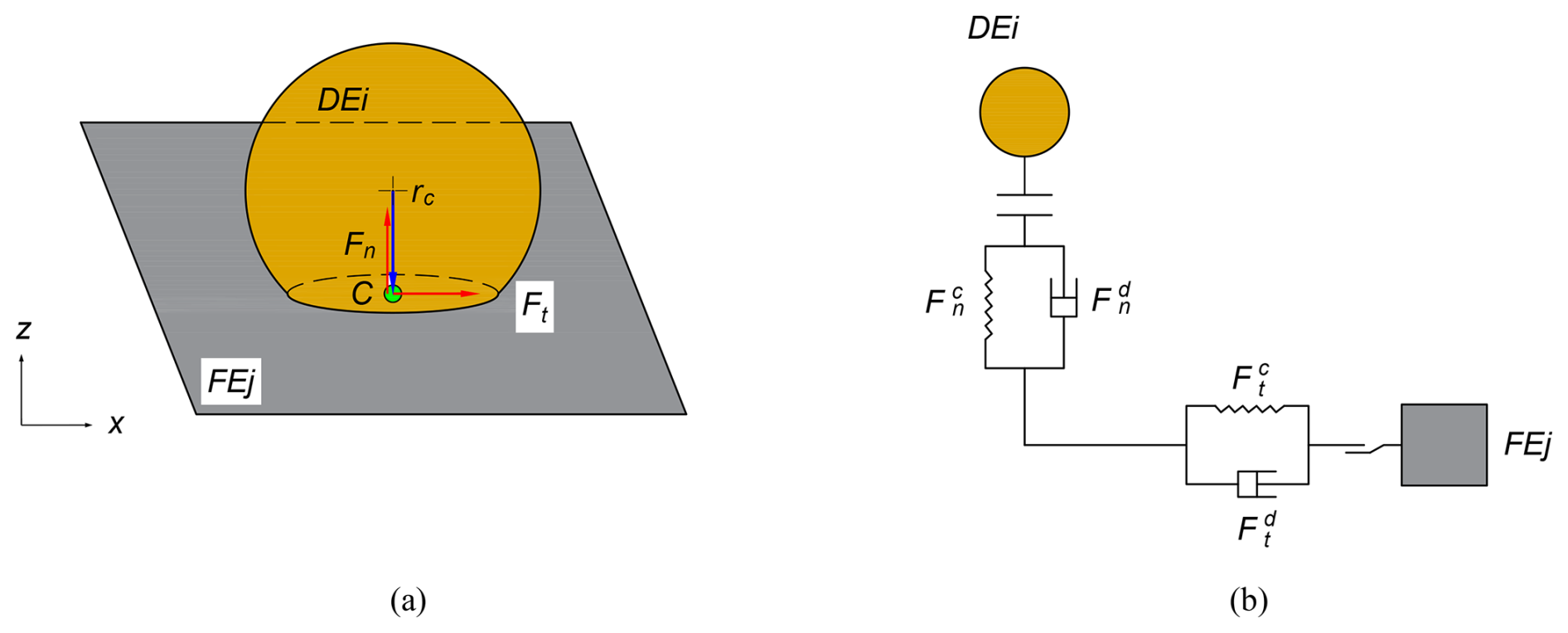
In this paper, the contact force between a discrete element (DE) and a finite element (FE) was calculated using the Hertz–Mindlin contact theory (Hertz, 1882; Mindlin and Deresiewicz, 1953). The interaction model between the two elements is illustrated in Fig. 1. In the contact model, Fn and Ft represent the normal force and tangential force, respectively, and rc denotes the distance between the center of mass and contact point C, as demonstrated in Fig. 1a. Figure 1b shows that the contact force comprises four components: the normal force , tangential force , normal damping force , and tangential damping force , which can be calculated by the following equations:
where δn and δt are the normal overlap and tangential displacement, respectively. vn and vt are the normal and tangential components of the relative velocity of the two particles. The normal stiffness (Kn), tangential stiffness (Kt), and damping ratio (β) can be calculated in terms of the equivalent Young's modulus (E∗), equivalent shear modulus (G∗), equivalent radius (R∗), and restitution coefficient (e) as
The terms E∗, R∗, G∗, and m∗ are defined as follows:
where E, ν, R, G, and m are Young's modulus, Poisson's ratio, the radius, and the mass of DE i and FE j, respectively.
2.3 Wheel–soil simulation system
In recent years, numerous studies have concentrated on the traction performance of planetary exploration vehicles during straight-line travel, yet there is a scarcity of research on steering characteristics. To comprehensively predict the motion characteristics of the lunar rover on soft lunar soil, this paper analyzes the steering performance of the flexible wheel under varying gravity environments using a coupled simulation approach. Figure 2 presents a schematic diagram of the flexible wheel during a steering maneuver. The center plane of the wheel is designated as the xz plane, with the wheel axis aligned along the y axis, thus establishing the wheel coordinate system. The actual traveling speed of the wheel is denoted as v, which can be decomposed into two components along the longitudinal and transverse directions, represented as vx and vy, respectively. The speed in the vertical direction is negligible.
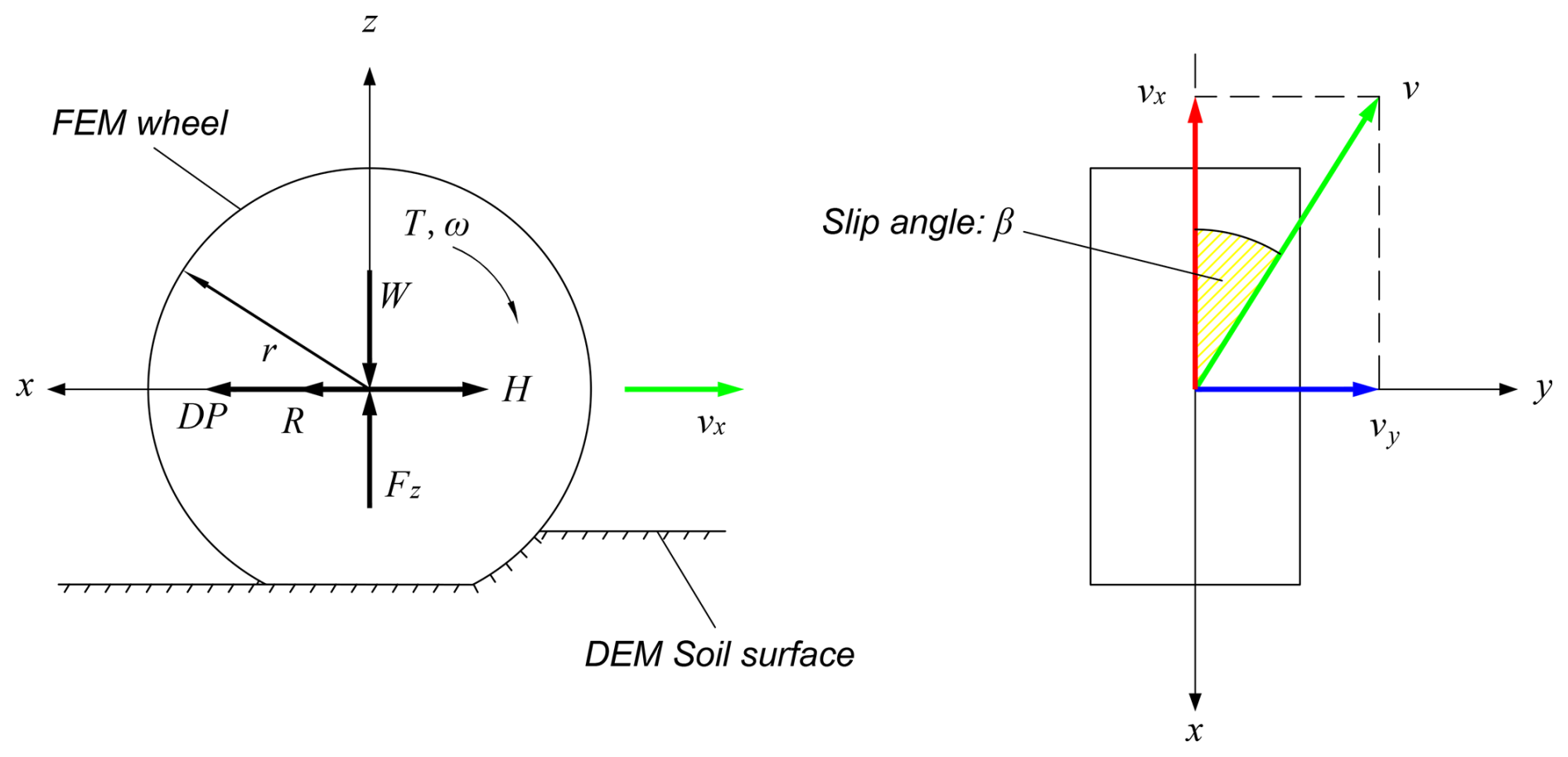
When the lunar rover travels on the soft lunar soil, the wheels slip due to the shear deformation of the lunar soil. During the steering maneuver, the calculation method for the longitudinal slip ratio is the same as that for straight-line driving, which is expressed as
where vx represents the forward speed of the wheel in the x direction, r is the radius of the wheel, and ω is the angular velocity of the wheel.
In addition to longitudinal slip, the steering condition also generates lateral slip. Different steering conditions are defined by the steering slip angle β:
The wheel reaches force equilibrium in the z direction under the load W and the vertical reaction force Fz of the lunar soil simulant. In the x direction, it is subjected to the thrust H of the lunar soil simulant particles and the driving resistance R. Therefore, the drawbar pull (DP) that can be provided in the x direction can be expressed as
When the vehicle turns, the wheels slip laterally, leading to a lateral force Fy acting on the wheels. This force arises from the combined effect of the soil on the wheels and the soil on the sides of the wheels.
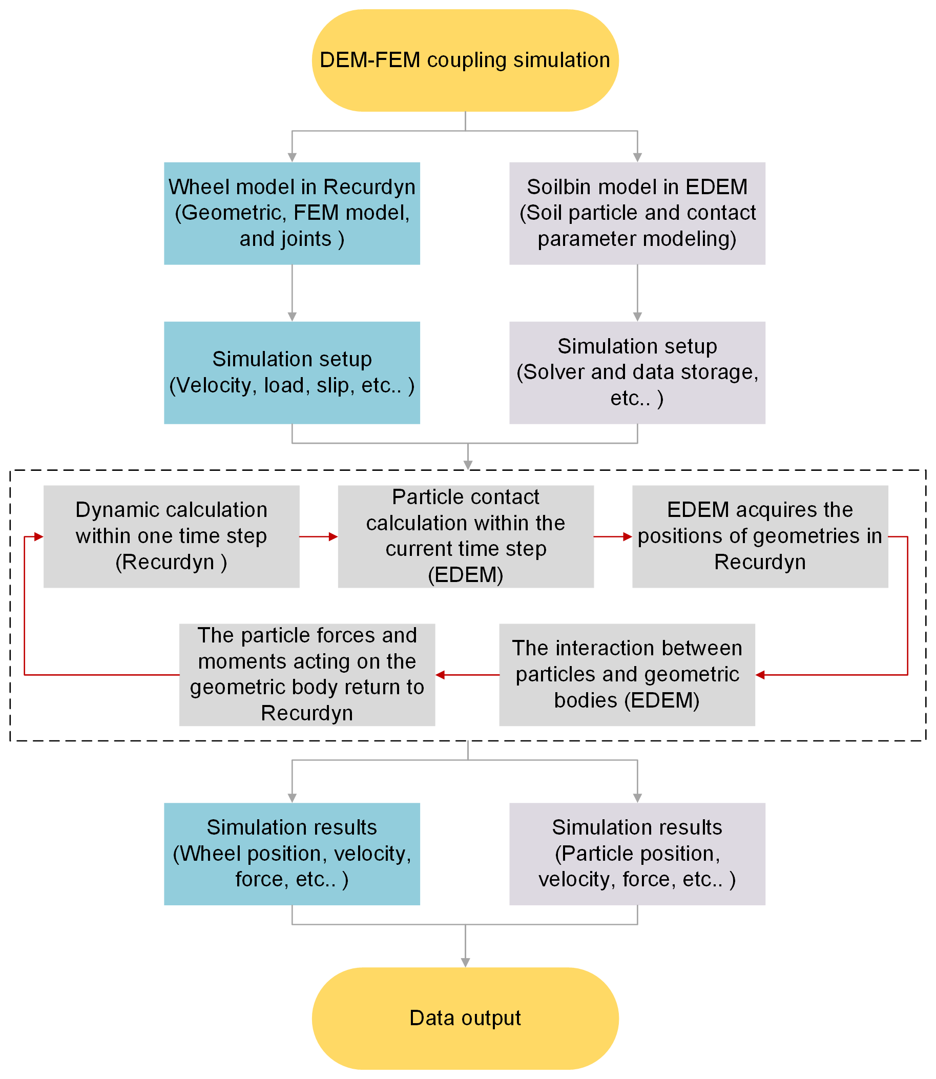
To accurately reproduce the interaction between the flexible metal wheel and the lunar soil simulant, this study conducted a coupled simulation using the RecurDyn and EDEM software. The finite element model of the wheel was developed in the RecurDyn software, and the DEM model for the lunar soil simulant was created in the EDEM software.
In the coupling simulation, the wheel model and the soil bin model are first established in the RecurDyn and EDEM software, respectively. Next, the wheel load, traveling speed, slip ratio, contact parameters of the lunar soil simulant, model storage path, and other parameters are set. After the simulation begins, the RecurDyn software calculates the wheel dynamics data within a time step, and EDEM calculates the particle interaction within the current time step and retrieves the geometric position of the wheel in RecurDyn from the coupling interface. Subsequently, the interaction between the particles and the wheel is calculated, after which the force and moment exerted by the particles on the wheel are transmitted to RecurDyn through the coupling interface. Lastly, the simulation results are output, and data analysis is conducted. The schematic diagram of the coupling simulation process is illustrated in Fig. 3.
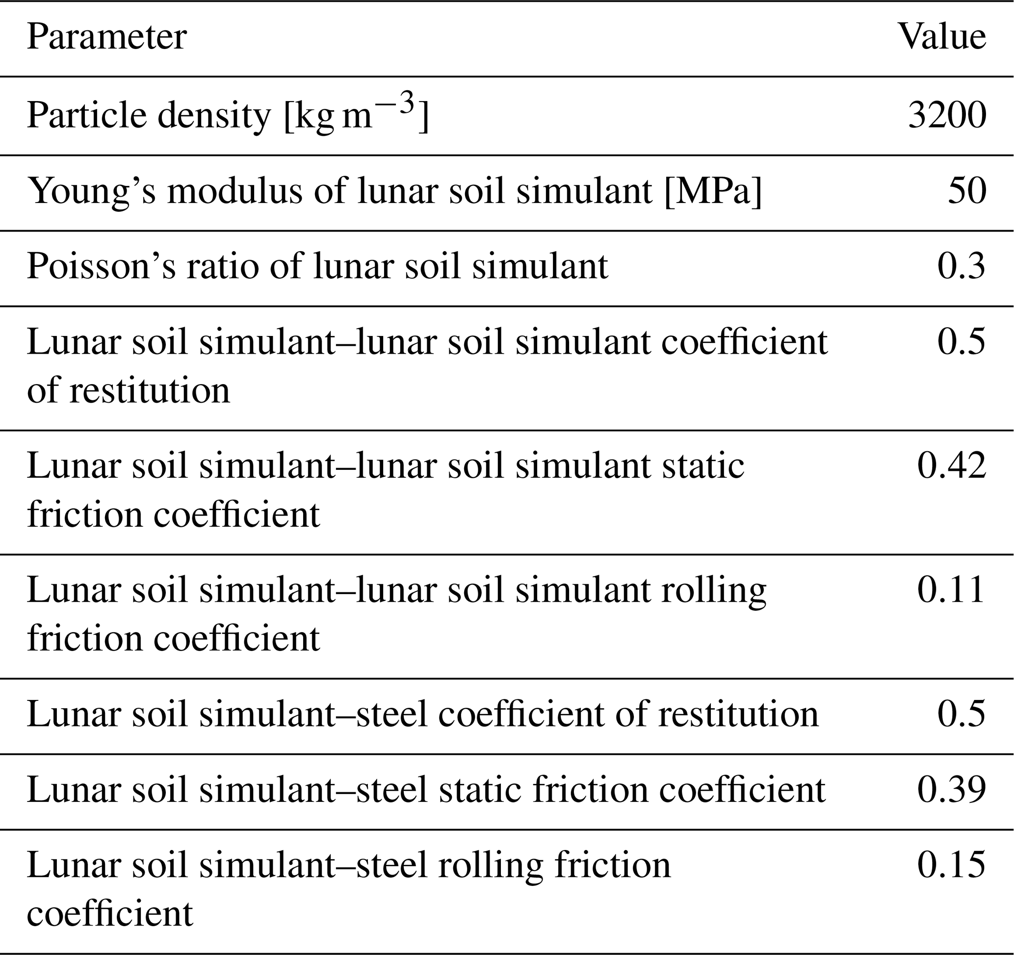
In our previous paper, the traction performance of a flexible wheel during straight-line travel was investigated (Zhu et al., 2023). As a continuation, this study investigated the traction performance during steering maneuvers. In this paper, the same contact parameters of the lunar soil simulant as those previously reported were used, as shown in Table 1.
Table 1Parameters of the lunar soil simulant used in the DEM simulation (Zhu et al., 2023).
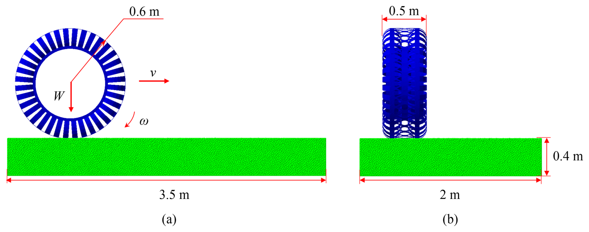
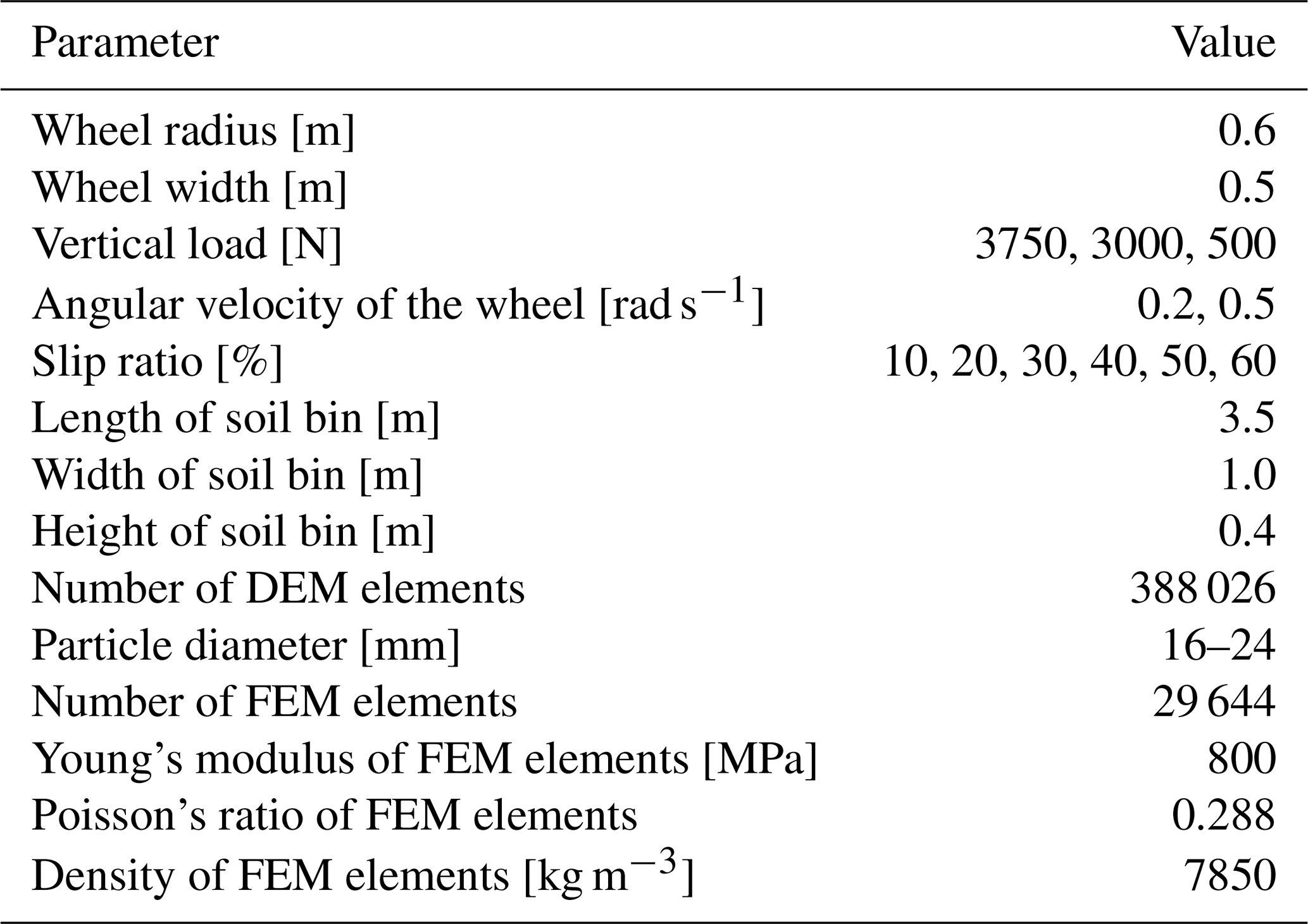
The wheel model and soil bin used in the simulation are illustrated in Fig. 4. The radius of the flexible wheel is 0.6 m, and its width is 0.5 m. The vertical load W comprises both the weight of the wheel and the external load applied to the center of the axle, which remains unchanged during the simulation process. The angular velocity and linear velocity of the wheel are represented by ω and v, respectively. The dimensions of the simulated soil bin are 3.5 m in length, 2.0 m in width, and 0.4 m in height, containing a total of 388 026 particles. The simulation parameters of the wheel soil system are shown in Table 2.
To investigate the steering performance of the flexible wheel in a low-gravity environment, simulations were conducted under two conditions: Earth gravity (1g) and Moon gravity (). The steering angles were set at 5, 10, 15, and 20°. The wheel speed was maintained at 0.6 m s−1, the slip ratio ranged from 10 % to 60 %, and the wheel loads were set at 3000 and 500 N, respectively.
Figure 5 presents the initial and final positions of the flexible wheel in the steering simulation. The simulation conditions are as follows: gravity at 1g, load at 3000 N, steering angle at 20°, and slip ratio at 60 %. Due to the compaction effect, ruts will form on the soil bin after the wheels have traversed the area. Due to the slip effect, the lunar soil simulant beneath the wheels flows backward. Additionally, the lateral earth-pushing effect on the side wall of the wheels during the steering process results in a distinct bulge of the simulated lunar soil on the right side of the wheels. The lateral bulldozing effect of the wheels during the steering maneuver also causes obvious bulging of the lunar soil simulant on the right side of the wheel.
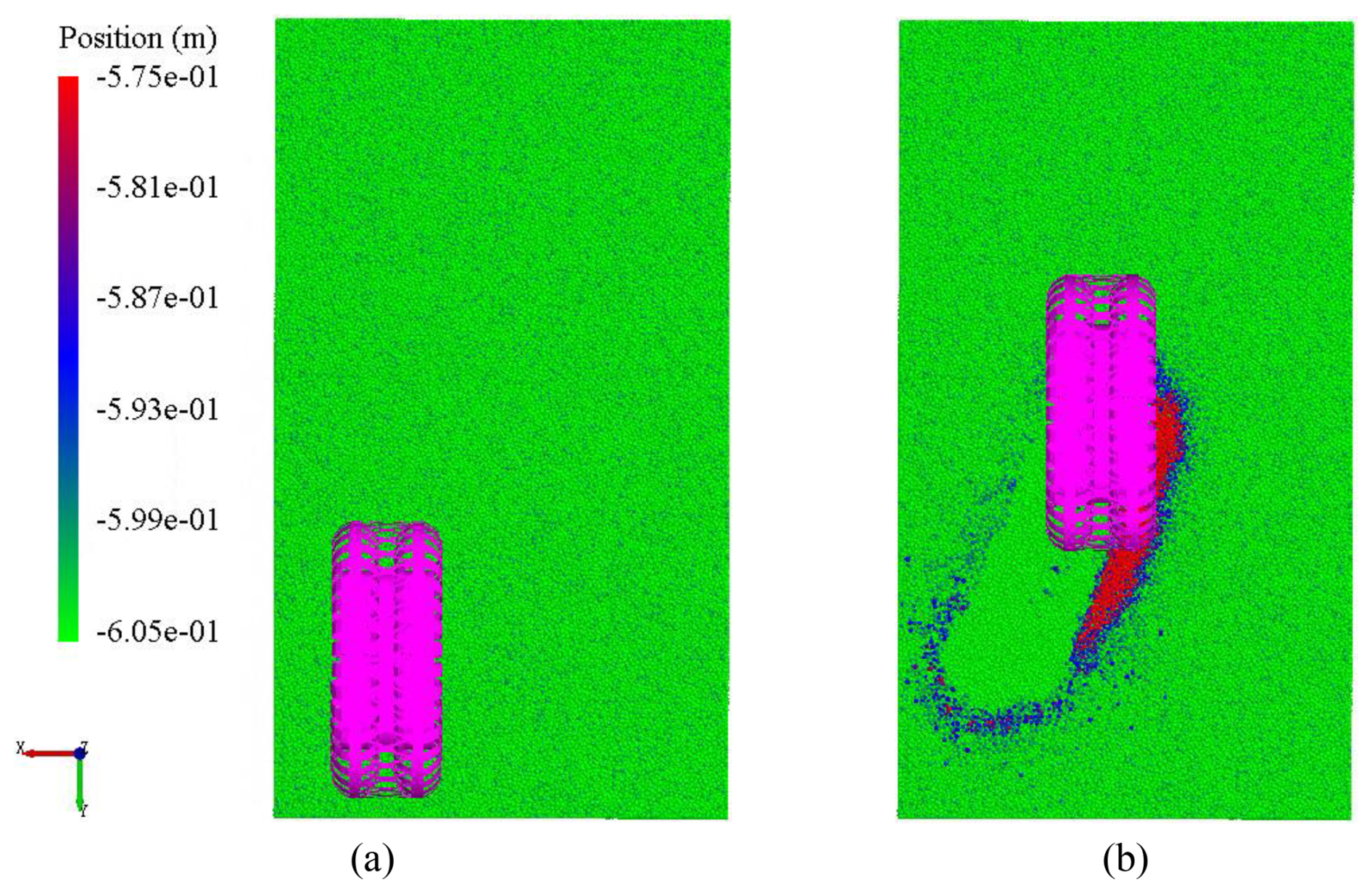
Figure 5Typical simulation image of flexible wheel steering maneuver. (a) Initial position; (b) end position.
3.1 Sinkage
Figure 6 illustrates the relationship between wheel sinkage and slip ratio under various gravity environments and steering angles. It can be observed from the figure that under different gravity and steering angle conditions, the wheel sinkage increases as the slip ratio increases, with the rate of sinkage accelerating alongside the slip ratio. This phenomenon occurs because the displacement of the lunar soil under the wheels increases with the slip ratio, leading to a greater volume of lunar soil being displaced backward by the wheels, which results in an increase in wheel sinkage.
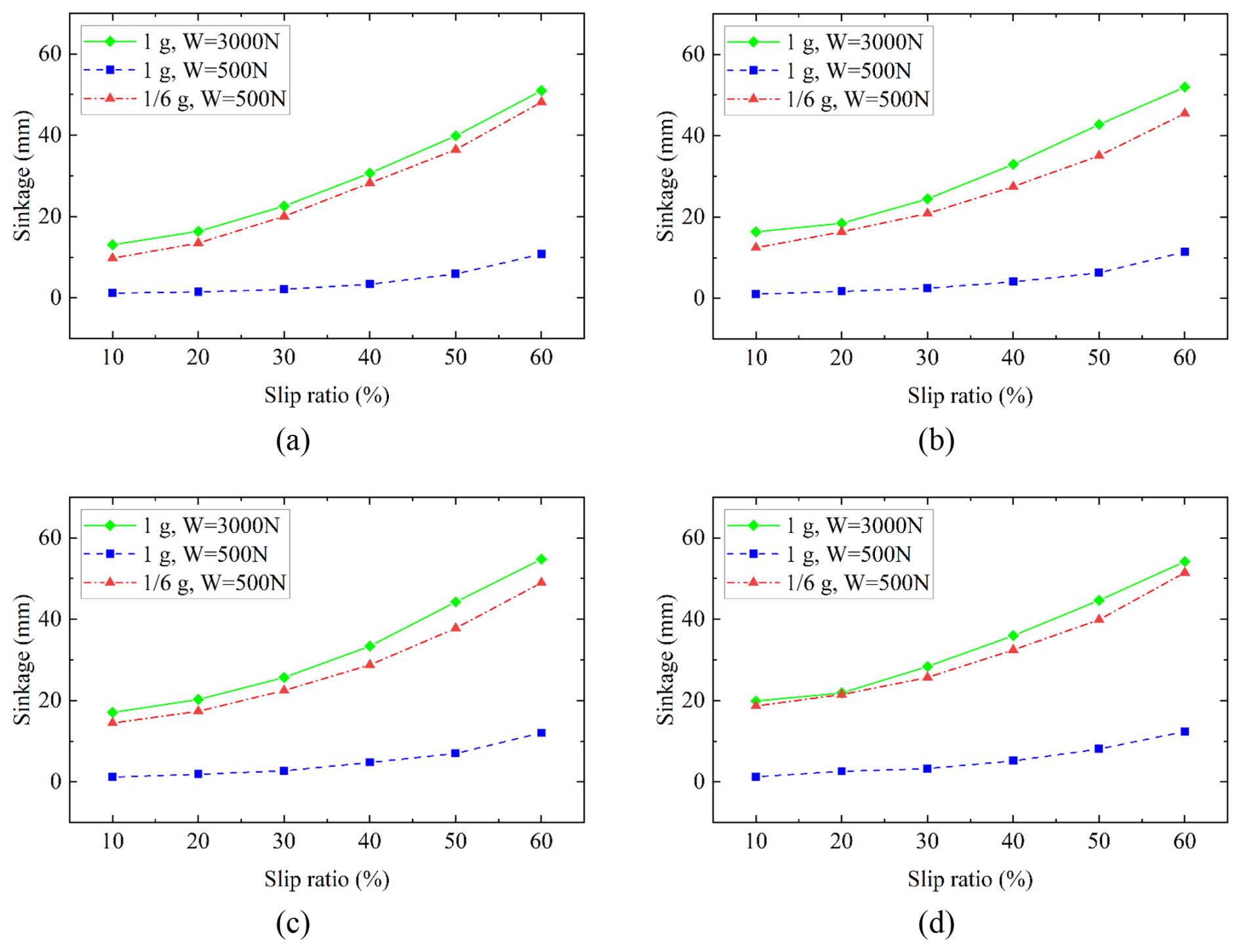
Figure 6Sinkage at different gravity and steering angles. (a) Steering angle of 5°, (b) steering angle of 10°, (c) steering angle of 15°, and (d) steering angle of 20°.
By comparing the working conditions of different gravity and wheel loads (1g, W = 3000 N; , W = 500 N), it can be found that the maximum differences in sinkage at steering angles of 5, 10, 15, and 20° were 25.2 %, 23.8 %, 15.2 %, and 10.7 %, respectively. The average differences were 12.6 %, 16.2 %, 13.5 %, and 7.1 %, respectively, suggesting that the influence of gravity on wheel sinkage is limited. This limitation arises because, as gravity decreases, both the wheel load and the lunar soil bearing capacity decrease, effectively canceling each other's effects on sinkage and resulting in nearly the identical wheel sinkage. This finding aligns with the conclusion obtained from the straight-line driving simulation. Notably, as the steering angle increases, the sinkage difference gradually diminishes. This occurs because an increase in steering angle leads to greater lateral slip, causing an increase in wheel sinkage due to lateral slip, while the difference in sinkage attributed to gravity decreases.
By comparing the two working conditions under the same gravity (1g) but with different wheel loads (W = 3000 N and W = 500 N), it was found that the maximum differences in sinkage at steering angles of 5, 10, 15, and 20° were 90.9 %, 93.3 %, 93.0 %, and 93.5 %, respectively. The average differences were 87.6 %, 87.4 %, 86.8 %, and 85.8 %, respectively, suggesting that under the condition that the bearing capacity of the lunar soil simulant remains unchanged, the load on the wheels significantly affects the wheel sinkage. In this group of tests, the average difference in sinkage at varying steering angles did not change significantly. This is attributed to the relatively large sinkage differences under the two loads, with a smaller proportion of sinkage differences arising from lateral slip.
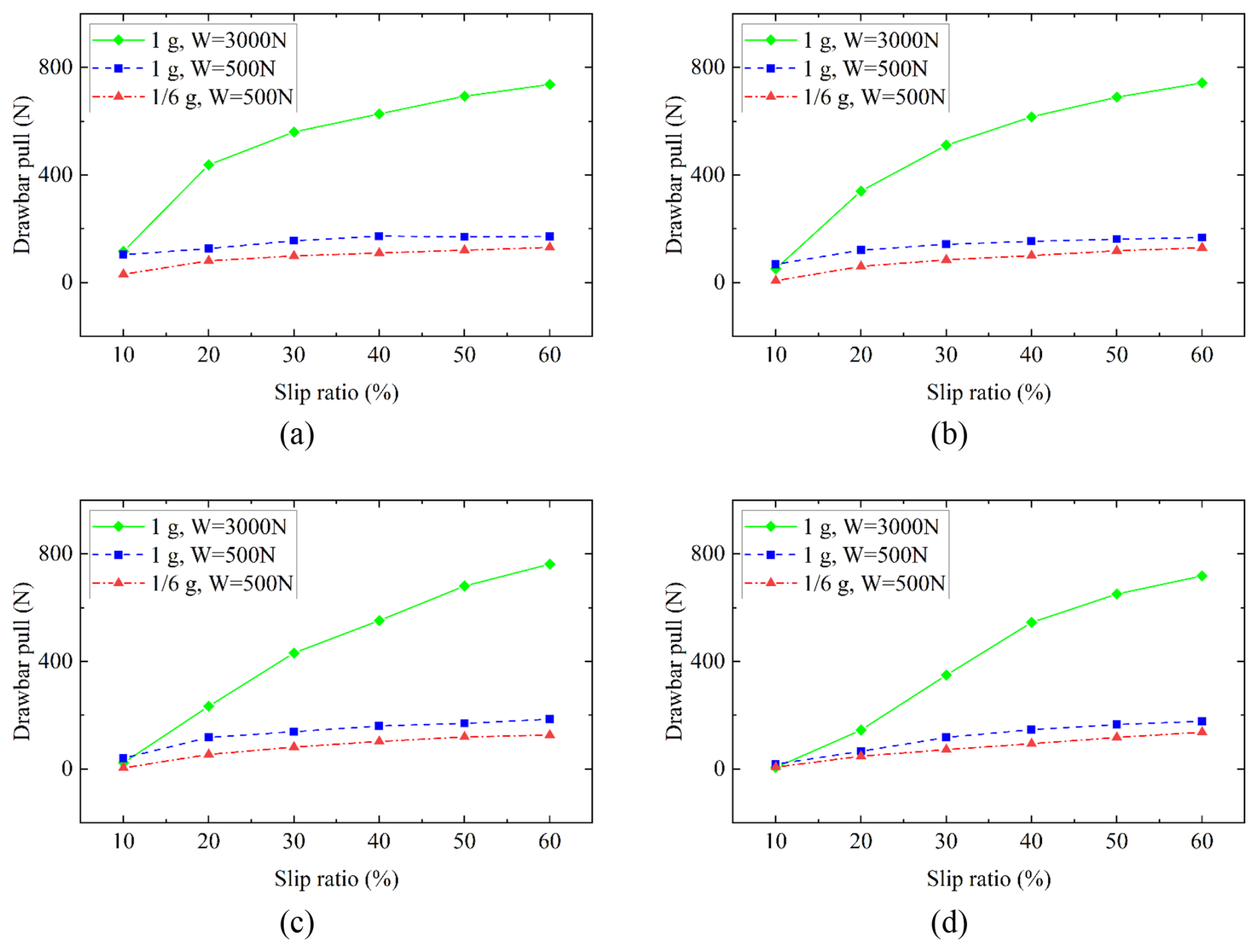
Figure 7Drawbar pull at different gravity and steering angles. (a) Steering angle of 5°, (b) steering angle of 10°, (c) steering angle of 15°, and (d) steering angle of 20°.
By comparing the simulation results across different steering angles, it is found that, as the steering angle increases, the sinkage gradually increases. Under the working conditions of 1g gravity and a load of W = 3000 N, when the steering angle rises from 5 to 20°, the sinkage at different slip ratios increases by an average of 26.7 %. Under the working conditions of 1g gravity and a load of W = 500 N, when the turning angle increases from 5 to 20°, the sinkage at different slip ratios increases by an average of 19.1 %. Under the working conditions of gravity and a load of W = 500 N, when the steering angle increases from 5 to 20°, the sinkage at different slip ratios increases by an average of 18.1 %. This phenomenon primarily occurs because an increase in the steering angle results in greater lateral slip of the wheels, which in turn leads to increased lateral shear displacement of the soil under the wheels and enhances the lateral pushing effect of the wheels, consequently increasing wheel sinkage.
3.2 Drawbar pull
Figure 7 shows drawbar pull curves under various gravity environments and steering angles. It can be observed from the figure that the drawbar pull under different working conditions increases with the slip ratio, whereas the rate of increase in the drawbar pull gradually slows down as the slip ratio increases. This is due to the longitudinal shear deformation of the lunar soil simulant under the wheel, which increases with the slip ratio, thereby generating a greater drawbar pull.
By comparing the working conditions under different gravity and loads (1g, W = 3000 N; , W = 500 N), the maximum differences in drawbar pull at steering angles of 5, 10, 15, and 20° were found to be 82.6 %, 86.0 %, 83.4 %, and 82.7 %, with average differences of 80.7 %, 83.4 %, 81.0 %, and 61.3 %, respectively. This indicates that gravity has a significant influence on drawbar pull. Specifically, as gravity decreases, the strength of the lunar soil simulant also decreases, leading to a reduction in the drawbar pull.
By comparing the working conditions at the same gravity (1g) but with different wheel loads (W = 3000 N and W = 500 N), the maximum differences in drawbar pull at steering angles of 5, 10, 15, and 20° were 76.7 %, 77.5 %, 75.7 %, and 75.2 %, respectively. The average differences were 63.1 %, 55.6 %, 44.1 %, and 21.9 %, respectively, suggesting that, although the bearing capacity of the lunar soil simulant remained constant, the load on the wheel significantly influenced the drawbar pull. Additionally, it was observed that the average difference in drawbar pull decreases as the steering angle increases.
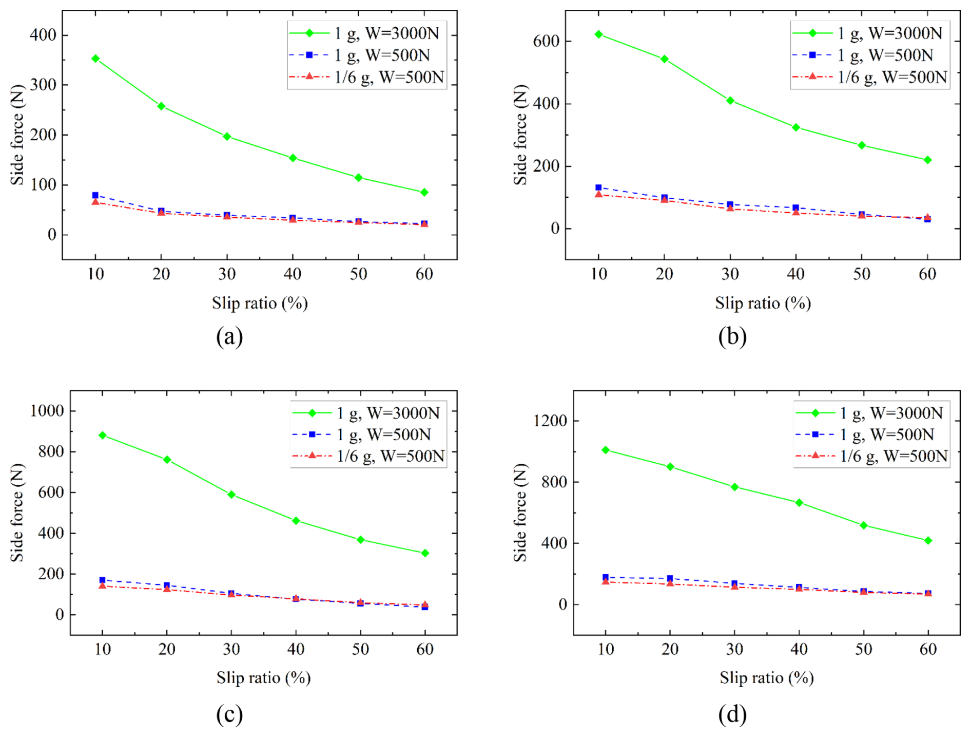
Figure 8Lateral force at different gravity and steering angles. (a) Steering angle of 5°, (b) steering angle of 10°, (c) steering angle of 15°, and (d) steering angle of 20°.
Analysis of the simulation results across different steering angles reveals that as the steering angle increases, the drawbar pull gradually decreases. Under the working conditions of a gravity of 1g and a load of W = 3000 N, as the steering angle increases from 5 to 20°, the drawbar pull with different slip ratios decreases by 95.0 % at most and 36.9 % on average. Under the working conditions of 1g gravity and a load of W = 500 N, when the steering angle increases from 5 to 20°, the drawbar pull with different slip ratios decreases by 82.6 % at most and 28.1 % on average. Under the working conditions of gravity and a load of W = 500 N, when the steering angle increases from 5 to 20°, the drawbar pull with different slip ratios decreases by up to 77.1 % and 26.3 % on average. Additionally, it was noted that at low slip ratios (10 %–30 %), the reduction in drawbar pull was more significant. This is because the longitudinal shear of the soil under the wheel decreases as the steering angle increases.
3.3 Lateral force
Figure 8 illustrates the lateral force curves under various gravitational environments and steering angles. It can be observed from the figure that the lateral forces under different working conditions all decrease as the slip ratio increases. This phenomenon occurs primarily because an increase in the slip ratio leads to greater disturbance of the wheel to the lunar soil simulant, which in turn reduces the strength of the lunar soil simulant and results in diminished lateral force.
By comparing the working conditions under different gravity and wheel loads (1g, W = 3000 N; , W = 500 N), the maximum differences in lateral forces at steering angles of 5, 10, 15, and 20° were found to be 83.2 %, 85.0 %, 84.0 %, and 85.4 %, respectively, and the average differences were 80.4 %, 84.1 %, 83.7 %, and 84.7 %, respectively. These results indicate that gravity significantly influences lateral force. Specifically, as gravity decreases, the strength of the lunar soil simulant also decreases, leading to a reduction in the lateral force.
In a comparison of working conditions under the same gravity (1g) but different wheel loads (W = 3000 N and W = 500 N), the maximum differences in lateral forces at steering angles of 5, 10, 15, and 20° were 81.6 %, 86.4 %, 87.3 %, and 83.2 %, respectively, while the average differences were 77.9 %, 81.8 %, 83.2 %, and 82.3 %, respectively. This indicates that, when the bearing capacity of the lunar soil simulant remains constant, the load on the wheel significantly affects the lateral force.
Analysis of the simulation results across various steering angles reveals that the lateral force increases with an increase in steering angle. Under the working condition of 1g gravity and a load of W = 3000 N, as the steering angle increases from 5 to 20°, the lateral force with different slip ratios increases by an average of 301.0 %. Similarly, under the working conditions of 1g gravity and a load of W = 500 N, when the steering angle increases from 5 to 20°, the lateral force with different slip ratios increases by 221.8 % on average. Under the working conditions of gravity and a load of W = 500 N, as the steering angle increases from 5 to 20°, the lateral force with different slip ratios increases by 211.7 % on average. This is mainly because as the steering angle increases, both the lateral speed of the wheels and the thrust effect gradually rise, resulting in a greater lateral force.
In this study, a wheel–soil coupling simulation system was constructed to simulate the interaction between the flexible metal wheels of a staffed lunar rover and the deformable terrain during steering maneuvers. This system accurately reproduces the discontinuous characteristics of lunar soil simulant and the deformation characteristics of flexible wheels, and simulations were conducted under Earth gravity (1g) and Moon gravity () conditions.
-
Under different gravity conditions (1g and ), the average sinkage differences at four steering angles were 12.6 %, 16.2 %, 13.5 %, and 7.1 %. These results indicate that the influence of gravity on wheel sinkage is limited. This is attributed to the fact that as gravity decreases, both the wheel load and the lunar soil bearing capacity diminish, and their effects on sinkage cancel each other out, leading to almost the same wheel sinkage. Comparing the two working conditions of different wheel loads (W = 3000 N and W = 500 N) revealed that the average sinkage differences at different steering angles were 87.6 %, 87.4 %, 86.8 %, and 85.8 %, suggesting that under the condition that the bearing capacity of the lunar soil simulant remains constant, the load on the wheels has significant effects on wheel sinkage.
-
The average drawbar pull differences were 80.7 %, 83.4 %, 81.0 %, and 61.3 %, indicating that gravity significantly influences drawbar pull. Specifically, as gravity decreases, the strength of the lunar soil simulant also decreases, leading to a reduction in the drawbar pull. Additionally, the average difference in drawbar pull decreases as the steering angle increases.
-
By examining lateral forces under different gravity conditions (1g and ), it was found that at steering angles of 5, 10, 15, and 20°, the average differences in lateral force were 80.4 %, 84.1 %, 83.7 %, and 84.7 %, respectively. This indicates that gravity significantly affects lateral force, as a decrease in gravity corresponds with a reduction in the strength of the lunar soil simulant, thereby decreasing lateral force.
Future work will focus on studying the traction performance of flexible wheels under various complex conditions, such as slope climbing and wheel inclining conditions. Additionally, optimization of the wheel tread structure and quantity of the flexible metal wheels will also be undertaken.
The data that support the findings of this study are available from the corresponding author upon reasonable request.
JZ performed the simulations and prepared the paper with contributions from all co-authors. YH carried out the validation. KW reviewed and revised the paper. MZ provided supervision and reviewed the paper.
The contact author has declared that none of the authors has any competing interests.
Publisher's note: Copernicus Publications remains neutral with regard to jurisdictional claims made in the text, published maps, institutional affiliations, or any other geographical representation in this paper. While Copernicus Publications makes every effort to include appropriate place names, the final responsibility lies with the authors. Views expressed in the text are those of the authors and do not necessarily reflect the views of the publisher.
The authors thank the reviewers for their critical and constructive review of the paper.
This research has been supported by the National Natural Science Foundation of China (grant no. 52075217).
This paper was edited by Liangliang Cheng and reviewed by four anonymous referees.
Cundall, P. and Strack, O.: The distinct element method as a tool for research in granular media, Part II, Department of Civil Engieneering Report, University of Minnesota, USA, 1979.
Hertz, H.: Ueber die Berührung fester elastischer Körper, Journal für die reine und angewandte Mathematik, 1882, 156–171, https://doi.org/10.1515/crll.1882.92.156, 1882.
Huang, H., Xu, S., Meng, Z., Li, J., and Zhang, J.: The sinkage characteristics and prediction of a planetary rover based on a similarity model experiment, Proceedings of the Institution of Mechanical Engineers, Part G: Journal of Aerospace Engineering, 233, 3762–3774, https://doi.org/10.1177/0954410018806808, 2018.
Iizuka, K. and Kubota, T.: Running Performance of Flexible Wheel for Lunar Rovers on Loose Soil, International Journal of Social Robotics, 4, 39–47, https://doi.org/10.1007/s12369-011-0104-0, 2011.
Jiang, M., Dai, Y., Cui, L., and Xi, B.: Experimental and DEM analyses on wheel-soil interaction, Journal of Terramechanics, 76, 15–28, https://doi.org/10.1016/j.jterra.2017.12.001, 2018.
Johnson, J. B., Kulchitsky, A. V., Duvoy, P., Iagnemma, K., Senatore, C., Arvidson, R. E., and Moore, J.: Discrete element method simulations of Mars Exploration Rover wheel performance, Journal of Terramechanics, 62, 31–40, https://doi.org/10.1016/j.jterra.2015.02.004, 2015.
Kobayashi, T., Fujiwara, Y., Yamakawa, J., Yasufuku, N., and Omine, K.: Mobility performance of a rigid wheel in low gravity environments, Journal of Terramechanics, 47, 261–274, 2010.
Lan, Q., Wang, Z., Ding, L., Yang, H., Gao, H., Richter, L., and Deng, Z. J. P. T.: DEM simulation and continuation algorithm of granular physical field for planetary wheel-terrain interaction, Powder Technology, 433, 119197, https://doi.org/10.1016/j.powtec.2023.119197, 2024.
Liang, Z., Chen, J., and Wang, Y.: Equivalent Acceleration Imitation for Single Wheel of Manned Lunar Rover by Varying Torque on Earth, IEEE/ASME Transactions on Mechatronics, 25, 282–293, https://doi.org/10.1109/TMECH.2019.2953330, 2020.
Mindlin, R. D. and Deresiewicz, H.: Elastic spheres in contact under varying oblique forces, ASME J. Appl. Mech., https://doi.org/10.1115/1.4010702, 1953.
Ozaki, S. and Kondo, W.: Finite element analysis of tire traveling performance using anisotropic frictional interaction model, Journal of Terramechanics, 64, 1–9, https://doi.org/10.1016/j.jterra.2015.12.001, 2016.
Rodríguez-Martínez, D., Van Winnendael, M., and Yoshida, K.: High-speed mobility on planetary surfaces: A technical review, Journal of Field Robotics, 36, 1436–1455, https://doi.org/10.1002/rob.21912, 2019.
Rubinstein, D., Shmulevich, I., and Frenckel, N.: Use of explicit finite-element formulation to predict the rolling radius and slip of an agricultural tire during travel over loose soil, Journal of Terramechanics, 80, 1–9, https://doi.org/10.1016/j.jterra.2018.09.002, 2018.
Sharma, G., Tiwary, S., Kumar, A., Suresha Kumar, H. N., and Keshava Murthy, K. A.: Systematic design and development of a flexible wheel for low mass lunar rover, Journal of Terramechanics, 76, 39–52, https://doi.org/10.1016/j.jterra.2017.12.002, 2018.
Takehana, K., Kizaki, S., Tanaka, T., Uno, K., and Yoshida, K.: Comparison of lunar rover wheel performance in soils with different cohesive properties, Journal of Terramechanics, 117, 101011, https://doi.org/10.1016/j.jterra.2024.101011, 2025a.
Takehana, K., Funabiki, K., Okuni, K., Hamabe, T., Niwa, K., Tanaka, K., and Yoshida, K.: Development and evaluation of high-speed single-wheel test for lunar exploration rover, Journal of Terramechanics, 119, 101057, https://doi.org/10.1016/j.jterra.2025.101057, 2025b.
Wang, S., Zou, M., Dang, Z., Chen, B., Zhou, T., and Su, B.: Modelling of flexible metal wheels for planetary rover on deformable terrain, Thin-Walled Structures, 141, 97–110, https://doi.org/10.1016/j.tws.2019.01.047, 2019.
Wiberg, V., Servin, M., and Nordfjell, T.: Discrete element modelling of large soil deformations under heavy vehicles, Journal of Terramechanics, 93, 11–21, 2020.
Xia, K.: Finite element modeling of tire/terrain interaction: Application to predicting soil compaction and tire mobility, Journal of Terramechanics, 48, 113–123, https://doi.org/10.1016/j.jterra.2010.05.001, 2011.
Yu, Q., Wu, D., Huang, S., Xu, H., Zhao, Y., and Cheng, H.: Research on the Driving Simulation Method of a Manned Lunar Rover System for Somatosensory Representation, Microgravity Science and Technology, 35, 56, https://doi.org/10.1007/s12217-023-10078-5, 2023.
Zeng, H., Xu, W., Zang, M., and Yang, P.: Experimental and Numerical Investigations of Tractive Performance of Off-Road Tires on Gravel Terrain, International Journal of Computational Methods, https://doi.org/10.1142/s0219876219500555, 2019.
Zhang, Y., Dai, J., Hu, W., and Negrut, D.: Using high fidelity discrete element simulation to calibrate an expeditious terramechanics model in a multibody dynamics framework, Multibody System Dynamics, https://doi.org/10.1007/s11044-024-10051-z, 2025.
Zhao, C. and Zang, M.: Analysis of rigid tire traction performance on a sandy soil by 3D finite element–discrete element method, Journal of Terramechanics, 55, 29–37, https://doi.org/10.1016/j.jterra.2014.05.005, 2014.
Zhao, C.-L. and Zang, M.-Y.: Application of the FEM/DEM and alternately moving road method to the simulation of tire-sand interactions, Journal of Terramechanics, 72, 27–38, https://doi.org/10.1016/j.jterra.2017.04.001, 2017.
Zhao, C., Zang, M., Chen, S., and Zheng, Z.: Improving the 3D Finite-Discrete Element Method and Its Application in the Simulation of Wheel–Sand Interactions, International Journal of Computational Methods, 15, https://doi.org/10.1142/s0219876218500597, 2018.
Zhao, S., Zhang, X., Zhang, Z., Bao, L., and Guo, Q.: Heavy-load variable stiffness lunar wheel based on adjustable tensegrity unit, Journal of Terramechanics, 120, 101074, https://doi.org/10.1016/j.jterra.2025.101074, 2025.
Zhou, G., Zhao, L., Du, Y., Zhang, H., Wen, L., and Zhang, R.: Irregular mesh wheels for lunar rovers: A comprehensive DEM study on traction and soil interaction, Proceedings of the Institution of Mechanical Engineers Part C-Journal of Mechanical Engineering Science, 239, 8472–8483, https://doi.org/10.1177/09544062251349699, 2024.
Zhu, J. Z., Zou, M., Shen, Y., Cao, H. T., Chen, Z., and Qi, Y. C.: 3D DEM-FEM simulation of the flexible metal wheel-soil interaction in low gravity environments, Proceedings of the Institution of Mechanical Engineers Part C-Journal of Mechanical Engineering Science, 237, 1267-1278, https://doi.org/10.1177/09544062221126630, 2023.
Zou, M., Zhu, J., Wang, K., Lin, Y., Jin, J., He, L., and Qi, Y.: Design and mechanical behavior evaluation of flexible metal wheel for crewed lunar rover, Acta Astronautica, 176, 69–76, https://doi.org/10.1016/j.actaastro.2020.06.010, 2020.