the Creative Commons Attribution 4.0 License.
the Creative Commons Attribution 4.0 License.
Study on the flow control of continuous post-spraying of gas-guide self-locking for weapon dispersed charging
Wei Lv
Ming Qiu
Wenhao Xing
Yuxiang Tao
Fei Guo
Jie Song
Excessive recoil severely restricts the application of high-power traditional guns on modern aircraft. The objective of the proposed dual-chamber dispersed charging high-pressure opening and low-pressure replying gas-guide self-locking control rear spray scheme is to address the shortcomings of existing lateral-nozzle weapons, which are unable to control the opening and replying of the rear spray channel. This results in the inefficient utilization of powder gas and a short duration of continuous rear spray. The scheme aims to further reduce the recoil impulse of the weapon by optimizing the opening and replying of the rear spray channel. In light of the two-phase flow of powder gas within the dual chamber, the gas-guide self-locking channel and lateral rear nozzle, coupled with the gas-solid coupling effect of the two spring-slider systems of the valve and the locking pin, a mathematical model is proposed. A model of the firing process of a 30 mm cannon with dispersed charging, gas-guide, and self-locking control rear spray has been established. The flow field in the two chambers and lateral rear nozzle, as well as the motion law of the valve and the locking pin, have been obtained. A further comparison is made with the firing process of a two-chamber weapon with a fixed-pressure valve, with the objective of analyzing the influence of the gas-guide self-locking control on the duration and total impulse of the powder gas post-spray. The results demonstrate that in comparison to existing dual-chamber fixed-pressure weapons, the dual-chamber gas-guide self-locking control post-spray weapon increases the post-spray duration from 4.682 to 7.434 ms, thereby extending the post-spray. The duration of the powder gas post-spray is increased by 58.78 %, while the total post-spray impulse rises from 414.12 to 454.77 N s. This results in a reduction of the weapon recoil impulse by 29.34 %. This study further reduces the weapon recoil impulse of the dual-chamber rear spray while simultaneously controlling the opening and resetting of the rear spray channel. This makes the design of the dual-chamber rear spray a more practical method of reducing the recoil impulse.
- Article
(1274 KB) - Full-text XML
- BibTeX
- EndNote
Aircraft guns mounted on helicopters or aircraft have significant advantages, such as a high rate of fire, high power, strong reliability and good mobility, and play an important role in close combat, destroying ground targets and providing air support (Zha and Chen, 2022). However, as the caliber of the aircraft gun increases, the large recoil generated during firing not only vibrates the gun itself but also impacts the fuselage and affects flight stability. Significantly reducing the recoil impulse while ensuring power is therefore a key bottleneck in solving the safe carriage of large-caliber gun barrels on aircraft.
At present, the technology of reducing the recoil impulse by utilizing the back spray of powder gas in the chamber has been successfully applied by configuring the back nozzle in the lateral direction of the weapon (Liao and Qiu, 2015). Qiu et al. (2022) proposed the recoil reduction technique of lateral back spraying of the barrel without affecting the continuous firing of the weapon, but the direct export of powder gases from the side of the body tube leads to a decrease in the muzzle velocity of the projectile. Qiu et al. (2021, 2023) proposed a lateral back spray sparse wave recoil reduction control method. Through the design of the back spray trigger device associated with the movement of the projectile to control the opening of the lateral back spray device, and at the same time achieve the effect of reducing recoil, the muzzle velocity of the projectile will not be reduced to achieve continuous fire. However, the method of the powder gas energy available to reduce the recoil is limited, and its recoil reduction efficiency generally does not exceed 45 %. Song et al. (2018a, b) studied a dual-chamber weapon, which did not consider the bidirectional flow between the front and rear chambers and thus did not fully utilize the powder gas in the front chamber to reduce the recoil impulse. Ma et al. (2021) proposed a baffle-controlled dual-chamber structure with a bidirectional flow, and the recoil reduction technology has made significant improvements in reducing recoil and maintaining the projectile's initial velocity compared to previous internal energy recoil reduction technologies. However, due to the limitations of the baffle structure, it cannot simultaneously consider the safety of the ammunition structure. Li et al. (2022) proposed a dual-chamber structure with a fixed-pressure valve, which ensures the safety of the weapon; however, the rear spray channel closes shortly after opening under the action of the valve piston, resulting in a short duration of powder gas rear spray, which cannot fully utilize the recoil-reducing effect of the nozzle.
In recent years, scholars have conducted extensive research (Bougamra and Lu, 2016; Cheng and Zhang, 2015, 2016; Hu and Zhang, 2018; Cheng and Zhang, 2019a) on the transient flow characteristics of high-temperature high-pressure propellant in the bore of gun barrels and other power devices. However, these studies mainly focus on the ignition structure of single-chamber systems, and the established propellant gas flow models are typically for relatively simple spatial structures such as cylinders (the bore of gun barrels) or rotating chamber cavities. Research on dual-chamber weapons (Song et al., 2018a, b) did not use a two-phase flow model but instead used an aggregate parameter method based on the Lagrangian hypothesis to describe the internal ballistic process by the average values of various variables in the post-firing space. This approach cannot describe the bidirectional propellant flow within the two chambers and the non-uniform pressure distribution, which directly impacts the weapon's internal ballistic performance, propellant burn behavior, and projectile acceleration curve, as well as the ultimate firing accuracy and reliability. It is essential to develop a more effective recoil reduction technology for guns. This paper aims to address the shortcomings of existing lateral-nozzle weapons, which are unable to control the opening and replying of the rear spray channel, and designs dynamic characteristics of the piston-spring system in the secondary valve device. Based on the two-phase flow internal ballistic theory, a weapon launching process model is established that combines the two-phase flow of gas-solid in the front and back chambers, the projectile motion, and the transient gas flow in the lateral back nozzle. Numerical simulations are carried out. We analyze the influence of various parameters on the initial velocity of the projectile, the recoil impulse, and the distribution of the flow field inside the bore, ultimately laying the theoretical foundation for the practical engineering application of the weapon.
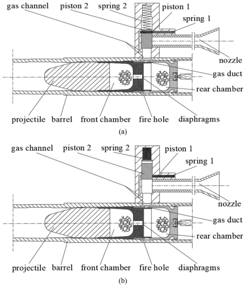
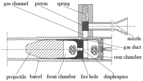
The basic principle of the decentralized charge gas-guide self-locking control post-spraying low-recoil weapon is shown in Fig. 1. First, the powder in the rear chamber is ignited by the artillery fire. If the gas pressure of the powder in the rear chamber is greater than the diaphragm-broken pressure of the fire (which generally cannot be too low), some of the high-temperature high-pressure gas from the rear chamber will flow through the fire hole into the front chamber to ignite the powder in the front chamber. At this stage, the pressure in the rear chamber is always greater than that in the front chamber. The combustion of the powder particles in both chambers and the continuous flow of gas from the rear chamber to the front chamber will rapidly increase the pressure in the front chamber, which will propel the projectile when it reaches the pressure required for projectile motion. At this point, the pressure in the rear chamber has not yet reached the start pressure of the secondary valve, so the rear chamber has not yet connected with the nozzle, as shown in Fig. 1a. When the pressure in the rear chamber exceeds the spring pre-load of piston 1, the piston gradually moves to its termination position under the action of spring 2 and gas, and removes the restriction on piston 2. Then piston 2 begins to move, the nozzle gradually opens fully, and the rear chamber powder gas is ejected at high velocity from the laterally expanding nozzle. Due to the direct connection of the nozzle to the atmosphere, the pressure in the rear chamber decreases faster than in the front chamber. When the pressure in the rear chamber is lower than that in the front chamber, some of the gas from the front chamber flows back to the rear chamber through the fire hole and is ejected from the nozzle together with the rear chamber gas, as shown in Fig. 1b. Only when the pressure in the rear chamber is lower than the spring force at the terminal position of piston 2 does piston 1 slowly return and close the nozzle passage. At the end of the firing cycle, the piston valve automatically returns under the action of the spring, enabling continuous firing.
3.1 Fundamental assumption
To date, no two-phase flow model has been established that takes into account the bidirectional flow of the two chambers in the weapon launch process. In order to obtain a theoretically relatively accurate and computationally accessible mathematical model, the following assumptions are made:
-
The group of powder particles is considered a pseudo-fluid with continuous medium characteristics, which conforms to the basic assumption of the two-phase flow dual-fluid model.
-
Combustion of the powder particles follows geometric combustion laws and exponential burn rate laws, with the geometric shape and size of the powder being strictly consistent.
-
The volume of the secondary valve piston chamber is small, and the flow of powder gas in the piston chamber is treated using a quasi-equilibrium zero-dimensional model (Cheng and Zhang, 2019a).
-
The flow of powder gas in the rear chamber, the inner cavity of the front chamber-barrel, and the lateral rear nozzle is a 1-D unsteady two-phase flow.
-
The high-temperature high-pressure powder gas is treated as an isentropic flow as it passes through the fire hole and curved tubes.
-
The solid powder particles are incompressible, and the material density of the powder is constant.
-
The viscous dissipation of the gas and the thermal losses to the barrel walls are neglected.
These assumptions have been practically applied and validated in a large number of studies on the internal ballistics of weapons and numerical calculations (Qiu et al., 2021; Song et al., 2018a, b; Ma et al., 2021; Li et al., 2022; Weng and Wang, 2006; Zhang, 2007; Menshov et al., 2019; Cheng and Zhang, 2019b; Cao and Zhang, 2019; Chen, 2010). The assumptions made in the modeling, such as treating the powder as a pseudo-fluid, assuming consistent particle geometry, employing zero-dimensional or 1-D flow models, considering isentropic gas flow, and neglecting viscous dissipation and heat loss, are necessary for simplification. However, they may introduce errors by overlooking factors like particle discreteness, real combustion variability, spatial pressure gradients, frictional losses, and heat transfer to the barrel, which could affect model accuracy under certain conditions. Although errors may occur in the calculations of this paper, they are relatively small and still within a reasonable range.
3.2 Modeling of two-phase flow in the rear chamber
The control equations for the internal ballistics of the two-phase flow in the rear chamber mainly include the mass conservation equation for the gas phase, the mass conservation equation for the solid phase, the momentum conservation equation for the gas phase, the momentum conservation equation for the solid phase, and the energy conservation equation for the gas phase. According to the different characteristics of the bidirectional flow in the two chambers and the flow of powder gas before and after the lateral rear injection, the equations are written in a conservation vector form.
Relevant auxiliary equations such as propellant combustion laws and interphase resistance can be referenced in Liao and Qiu (2015) and Weng and Wang (2006).
3.3 Fire hole two-phase flow model
According to the basic assumption (5), the flow of propellant gas flow through the fire hole can be considered as an isentropic flow. The gas flow parameters at the fire hole depend on the area ratio of each section and the pressure ratio on both sides of the fire hole. After the propellant in the rear chamber is ignited and breaks through the fire hole membrane, the pressure in the rear chamber is greater than that in the front chamber, so the flow at the fire hole is a forward critical flow. When the propellant in the front chamber is ignited, the pressure in the front chamber rises rapidly, and the flow becomes a forward subcritical flow. With the opening of the rear spray channel, the pressure in the rear chamber decreases continuously. When the pressure in the rear chamber is lower than that in the front chamber, the propellant gas in the front chamber will flow back into the rear chamber, forming a reverse critical flow and a reverse subcritical flow. Based on the above analysis, the equations for the mass flow rate and flow velocity of propellant gas and propellant particles at the fire hole are specifically listed.
-
The gas-phase flow rate ug' and the solid-phase flow rate up':
-
The gas-phase mass flow rate mg′ and the solid-phase mass flow rate mp′:
3.4 Front chamber-interior trajectory in the barrel two-phase flow model
Since the propellant gas in the front chamber will exchange flow with the rear chamber through the fire hole, the two-phase flow equations for the front chamber-body tube chamber are written in the following conservative vector form:
When performing interior ballistics programming calculations, the difference between the front chamber-body tube chamber and the rear chamber lies in the treatment of boundary conditions.
3.5 Gas flow model at the gas-guide hole
The propellant gas flow through the gas-guide hole is considered to be isentropic flow. As piston 2 begins to move, the side spray channel begins to open. At this point, due to the higher pressure in the rear chamber relative to the pressure in the lateral nozzle, a critical flow is formed at the gas-guide hole; as the propellant gas continues to flow from the rear chamber into the lateral nozzle, the pressure in the nozzle continues to increase, while the pressure in the rear chamber gradually decreases. At this point, the flow at the gas-guide hole transitions to subcritical flow. As the lateral nozzle is connected to the outside atmosphere, the pressure in the lateral nozzle is always lower than the pressure in the rear chamber, thus preventing backflow (Liao and Qiu, 2015). Based on the above analysis, the equations for the mass flow rate and flow velocity of the propellant gas and propellant particles at the gas-guide hole are specifically listed.
-
The gas-phase flow rate uiv and the solid-phase flow rate uip:
-
The gas-phase mass flow rate miv and the solid-phase mass flow rate mip:
3.6 Piston chamber gas-solid coupled dynamics model
According to the basic assumption (3), due to the small volume of the piston chamber, the propellant gas flow in the secondary valve piston chamber is treated using a zero-dimensional model. After the propellant gas flows into the piston chamber through the gas-guide hole, piston 1 and piston 2 will reciprocate under the action of the propellant gas and springs. In the secondary valve piston chamber, only gas-phase flow is considered. There is a mass and energy exchange of the propellant gas between the rear chamber, piston chamber, and spray tube. Since the piston directly controls the opening and closing of the lateral after-burning channel, there must be good sealing inside the piston valve, so the gap between the piston and piston chamber is not considered. Based on the conservation equations for mass, momentum, and energy in the piston chamber, the gas dynamics in the piston chamber and the equations controlling piston movement are as follows.
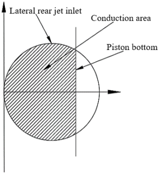
Once piston 1 reaches the final position, piston 2 starts to move, and the lateral after-burning channel gradually opens, as shown in Fig. 2. The relationship between the open area of the back spray channel and the piston displacement can be expressed as follows.
The back spray pipe is directly connected to the atmosphere, and the pressure of the propellant gas in the piston chamber is always greater than the external atmospheric pressure. Therefore, only forward critical flow and forward subcritical flow exist at the lateral after-burning inlet. The equation is as follows.
3.7 Lateral-nozzle two-phase flow model
The lateral nozzle is simplified to a straight pipe, with the lateral nozzle inlet as the starting point. Only the unidirectional flow of propellant gas is considered inside the pipe, similar to the two-phase flow model in the chamber. The control equation for the flow of propellant gas is as follows.
The fluid motion control equation in the lateral after-burning pipe needs to consider the exchange of mass, momentum, and energy of the propellant gas between the lateral after-burning pipe and the piston chamber, reflected in the term K in Eq. (21).
4.1 Difference scheme
The control equations for the dual chamber and lateral nozzle are discretely solved using the second-order accurate TVD-MacCormack differencing scheme (Liang et al., 2007). The control equations for the piston chamber are solved using the second-order Runge–Kutta method (Liao and Qiu, 2015). For the time step, if the lateral spray channel is not open, the value obtained from the CFL condition (Weng and Wang, 2006) in the chamber's computational domain is taken; if the lateral spray channel is open, the minimum value obtained from the CFL condition in the chamber and exhaust pipe computational domains is taken.
4.2 Definite solution condition
The initial conditions are determined based on the initial loading conditions. As the dual-chamber gas-guide self-locking controlled rear jet low-recoil weapon has multiple chambers, different boundary conditions must be established for each chamber. In particular, the boundary conditions of the front chamber are relatively complex and vary with time at each stage of the firing process. The states inside the two chambers, piston chamber, and lateral after-burning pipe before firing are taken as the initial states. Depending on the changes in the weapon-firing stages, the following boundary conditions are included in the calculation process.
-
The left and right boundaries of the rear chamber are solid wall boundaries, treated by the second mesh mirror reflection method (Menshov et al., 2019).
-
The bottom of the front chamber is a solid wall boundary, treated by the second mesh mirror reflection method (Menshov et al., 2019).
-
In the projectile base boundary, the mirror reflection method is used before the projectile motion; after the projectile motion, the motion control volume method is used, which enlarges the chamber domain due to the projectile motion, and the grid length Δx2 of the projectile base control volume increases continuously. When , the grid of the projectile base control volume grid splits, creating a new grid, and then Δx2−Δx is reassigned to Δx2, repeating this process.
-
In the throat boundary and the lateral after-burning nozzle boundary, free outflow boundary conditions are used to treat subsonic and supersonic outflows.
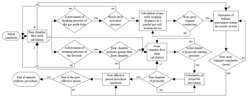
The process of the solution method is shown in Fig. 3. After the ignition of the propellant in the rear chamber, the flow fields in the rear chamber and the piston chamber begin to couple, and the effect of the propellant gas flow at the gas-guide hole is reflected in the K term of Eqs. (1) and (21), as well as in the miv term of Eq. (15); after the fire disk ruptures, the flow fields of the front and rear chambers start to couple, and the effect of propellant gas flow at the fire disk is reflected in the I term and J term of Eqs. (1) and (12), as well as in the mg' term of Eq. (10). After the lateral after-burning channel is opened, the flow fields in the piston chamber and lateral after-burning pipe start to couple. The effect of propellant gas flow at the lateral after-burning inlet is reflected in the Hn term of Eq. (21) and the mit term of Eq. (19).
5.1 Parameters and motion status of dual-chamber gas-guide self-locking controlled rear jet low-recoil weapon
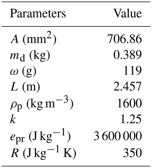
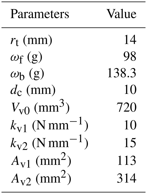
Based on a 30 mm caliber ordinary chain gun, according to the principle of Fig. 1, the ordinary chain gun was modified into a low-recoil weapon after injection controlled by a dual-chamber two-stage valve. The known structure and powder parameters are shown in Table 1. The entire firing process of the weapon is numerically simulated and compared with a fixed-pressure valve dual-chamber weapon.
During the weapon-firing process, the opening time of the lateral back spray inlet is controlled by the movement of two valve pistons. It can be seen from Eq. (17) that the characteristics of the piston are mainly determined by factors such as the size of the gas-guide hole, the cross-sectional area of the locking pin, and the spring stiffness. Due to the coupling of the four flow fields of the front and rear chambers, the piston chamber, and the lateral back spray pipe, there is a complex non-linear relationship between the factors affecting the timing of the opening of the lateral back spray inlet. In order to achieve the best recoil reduction effect while ensuring that the initial velocity of the projectile is not reduced, reasonable parameter matching can only be achieved through a large number of numerical calculation experiments in specific cases. Based on the above analysis, a set of good parameters is obtained by searching for the best match of each parameter through a large number of calculations, as shown in Table 2.
According to the parameters in Table 2, the motion state of the gas-guide self-locking control rear spray weapon is obtained by numerical simulation. Taking the moment of starting ignition as the starting moment, at 0.916 ms the powder gas from the rear chamber flows into the front chamber; at 1.311 ms the nozzle starts to open; the projectile starts to move at 1.554 ms; at 2.161 ms the powder gas from the front chamber flows back into the rear chamber; at 2.25 ms the lateral rear spray channel opens completely; at 5.373 ms the nozzle starts to close; at 5.627 ms the projectile comes out of the rifled port, and the internal ballistic period ends and enters the after-effect period; at 8.745 ms the lateral rear spray channel completely closes; and at 23.233 ms the after-effect period ends.
5.2 Flow field analysis in the rear chamber
Figure 4a–d shows the distribution curves of the bore pressure, gas density, gas velocity, and solid velocity in the rear chamber of the two-chamber secondary valve weapon along the axial direction of the barrel at different times. In the figures, the bottom of the bore is defined as the zero point of the horizontal axis, and the direction towards the muzzle is the right direction of the horizontal axis. According to Fig. 4, during the period from 1.554 to 8.745 ms, the lateral rear nozzle undergoes a process from gradually opening to completely opening and then gradually closing until completely closing. When the nozzle starts to conduct, because the pressure inside the rear chamber is much higher than that inside the piston chamber and the rear nozzle pipe, the powder gas rapidly flows into the rear nozzle pipe through the piston chamber, resulting in interruptions at the position where the rear chamber is connected to the nozzle pipe (at the gas-guide hole) and discontinuous pressure and velocity curves.
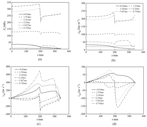
Figure 4Flow field distributions in the back chamber: (a) pressure, (b) gas density, (c) gas velocity, and (d) solid velocity.
Figure 4a and b shows the distribution diagrams of the bore pressure and gas density along the axial direction of the barrel in the rear chamber at different times. It can be seen that the trend of the density distribution curve is similar to that of the pressure distribution curve at each instant. In the time between 0.916 and 2.25 ms, the powder particles are fully burned, the powder gas is produced continuously, the pressure and gas density in the rear chamber increase continuously, and the powder gas flows into the piston chamber and the rear spraying channel. When it reaches a certain pressure, the locking pin is unlocked and the valve piston moves upward so that the rear spraying channel is opened rapidly. The powder gas is sprayed from the rear nozzle, and the pressure and gas density inside the rear chamber are reduced. The pressure and density inside the rear chamber reach a maximum at 2.25 ms and start to decrease rapidly; then the rear spray channel opens completely at about 2.25 ms. From 2.25 to 8.745 ms, the powder gas continued to be ejected from the rear jet pipe until the pressure in the rear chamber decreased. The locking pin was replied to reset the valve piston, the rear jet channel was gradually closed, and the chamber pressure and gas-phase density in the rear chamber decreased gently. After 8.745 ms, the density in the rear chamber along the axial direction of the body tube increased due to the complete closure of the rear spray channel, the pressure and density in the rear chamber no longer decreased at the guide hole, and the small amount of powder gas remaining in the chamber was only flowing out of the chamber opening.
It can be seen from Fig. 4c and d that from the time when the rear spray channel begins to open until it is completely closed, the combustion gases and a small amount of propellant particles at the rear chamber vent hole will flow into the vent hole, causing the gas-phase and solid-phase velocities near the vent hole on the side closer to the bottom of the chamber to increase. Meanwhile, the velocity on the side closer to the bottom of the projectile becomes negative due to the opposite direction of gas flow, forming a velocity shock wave.
5.3 Analysis of flow field in front chamber-barrel
Figure 5a–d shows the distribution curves of pressure, gas density, gas velocity, and solid velocity along the axis of the barrel in the front chamber of the dual-chamber piston weapon at different times.
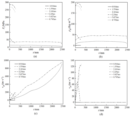
Figure 5Flow field distributions in the front chamber: (a) pressure, (b) gas density, (c) gas velocity, and (d) solid velocity.
As can be seen from Fig. 5a and b, it can be that the powder particles in the front chamber are not yet ignited at 0.916 ms, the chamber pressure is maintained at the standard atmospheric pressure, and the gas-phase density is 0. From 1.554 to 2.25 ms, the bottom pressure of the projectile rises to 60.44 MPa, which is larger than the projectile starting pressure. The projectile moves, and the space behind the projectile begins to increase at the time of the internal ballistic time of 1.554 ms. The powder particles continue to burn to generate powder gas, and the chamber pressure and gas-phase density increase with time. At 2.161 and 2.25 ms, due to the accelerated propulsion of the projectile in the barrel, the axial distribution of each internal ballistic parameter in the bore is uniform and the range gradually increases. At 5.627 ms, the powder particles have burned completely, the projectile is out of the breech, and a large amount of powder gas in the chamber is discharged from the breech and nozzle, resulting in a significant decrease in the pressure and gas-phase density in the chamber at the breech opening. Then, 5.627 ms later, the powder particles have burned completely, and the pressure and gas-phase density have decreased as a whole and are uniformly distributed axially inside the body tube. At 8.745 ms, the rear spray channel is closed, the remaining powder gas in the rear chamber flows to the front chamber, and the pressure further decreases and is maintained at 10 MPa.
From Fig. 5c, it can be seen that at 1.554 ms, the projectile begins to move, the bottom boundary condition changes to a dynamic boundary, and the bottom gas-phase velocity and the projectile velocity remain consistent. From 2.161 to 2.25 ms, the projectile has been moving for a certain distance during this period, and the distribution range of the gas-phase velocity along the axial direction is increasing. The projectile exits the bore at 5.627 ms, the gas-phase velocity in the bore is approximately linearly distributed along the axial direction of the barrel, and the boundary of the projectile bottom movement becomes the boundary of the breech-free outflow. At this time, the gas-phase velocity in the breech is the initial velocity of the projectile of 960.26 m s−1. At 8.745 ms, the remaining powder gas in the chamber flows to the muzzle, resulting in a significant increase in the velocity of the gas phase of the chamber, with a velocity of 923.64 m s−1. As can be seen in Fig. 5d, there is no powder gas generated in the front chamber at 0.916 ms, so there is no powder particle movement. The powder particles are pushed by the powder gas at 1.554 ms, and the movement velocity is relatively slow due to the larger powder particle mass. From 2.161 to 2.25 ms, the powder particles are further burned to generate more powder gas, and the velocity of solid-phase particles increases and is basically linearly distributed along the axial direction of the body tube. With the movement of the projectile, the space behind the projectile increases, and the distribution distance of the powder particles becomes longer and longer. Following this, 5.627 ms later, the powder particles are completely burned, and the solid-phase velocity is zero.
5.4 Flow field analysis in lateral nozzle
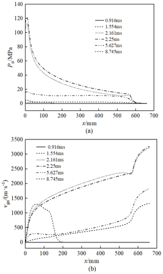
Figure 6 shows the distribution curves of the flow field along the axial direction in the lateral nozzle at six different times after the fire detonation. Before 0.916 ms, the back spray channel is not yet on, the pressure in the nozzle is the initial atmospheric pressure, and the gas-phase velocity is 0. At the moment of 1.554 ms, shortly after the opening of the lateral nozzle, due to the injection of high-pressure propellant gas, there is a sudden increase in both gas pressure and velocity at the entrance of the lateral nozzle, indicating that the propellant gas has not yet filled the entire lateral nozzle. After 2.161 ms, as the lateral nozzle gradually opens, more and more propellant gas flows into the lateral nozzle. At this point, the propellant gas has filled the entire lateral nozzle and continues to expand. Therefore, the gas pressure decreases along the axial direction of the nozzle, while the velocity increases; due to further expansion and acceleration of the propellant gas at the expansion nozzle, the gas velocity undergoes a significant increase, while the pressure undergoes a significant decrease, indicating that the expansion nozzle can impart large after-injection momentum to the propellant gas.
5.5 Analysis of piston chamber pressure change and piston recovery movement
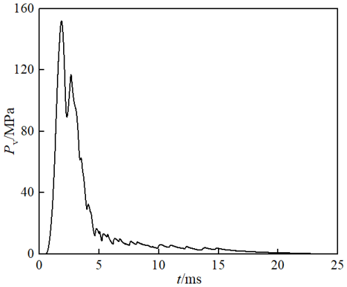
Figures 7 and 8 show the curves of pressure and piston displacement in the piston chamber as a function of time. Figure 7 shows that the rear spray passage begins to open at 1.311 ms. At this point, the bore pressure in the piston is still increasing due to the very small conduction area and the rapid combustion of the powder particles in the rear chamber, which generates a large amount of powder gas. After 1.849 ms, a significant proportion of the powder particles in the bore are completely burned. In addition, with the gradual opening of the lateral rear spray passage, the powder gas in the piston chamber is rapidly discharged from the nozzle, resulting in a significant intermittent pressure in the piston chamber. After 2.297 ms, as the powder gas continues to flow from the rear chamber into the piston chamber, there is a brief increase in pressure in the piston chamber. At 2.648 ms, when the powder particles in the rear chamber have completely burned off and the rear jet passage is fully open, the amount of powder gas flowing into the nozzle from the piston chamber is greater than the amount of powder gas flowing into the piston chamber from the rear chamber, so the pressure in the piston chamber begins to gradually decrease. Between 4.656 and 8.745 ms, the pressure in the piston chamber shows slight oscillations due to the slowing down of the flow rate in the front and rear chambers and the movement of the piston as it returns.
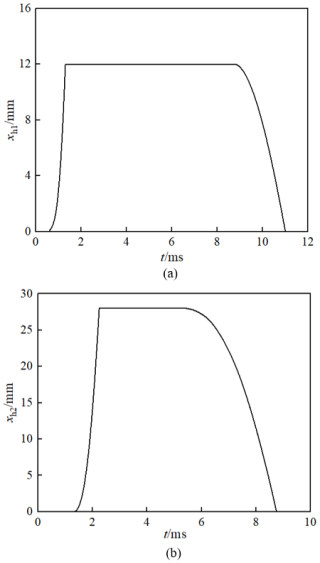
Figure 8 shows that the motion of the two pistons is mutually constrained. At 0.611 ms, piston 1 begins to accelerate under the action of the powder gas and the spring force; at 1.311 ms, it reaches its limit position, at which point the motion constraint on piston 2 is released and piston 2 begins to accelerate, and the lateral back spray passage begins to open. At 2.25 ms, piston 2 reaches its limit position, at which point the back spray passage is fully open. At 5.373 ms, as the spring force on piston 2 is greater than the force exerted by the gas in the piston chamber, piston 2 begins to retract, and the back spray passage gradually closes until at 8.744 ms piston 2 is fully retracted and the back spray passage is fully closed. At this point, piston 1 begins to retract under the action of the spring until it is fully retracted at 11.886 ms, at which point the secondary valve device returns to its initial state.
It is noteworthy that at a firing rate of 1000 rounds per minute for a typical single-barrel artillery gun, the two pistons in the secondary valve device must complete their reset within 60 ms. Consequently, the secondary valve's control over the lateral backflow of propellant gas in the dual-chamber configuration does not compromise the weapon's sustained firing capability.
5.6 Comparative analysis of performance of rear spray control device
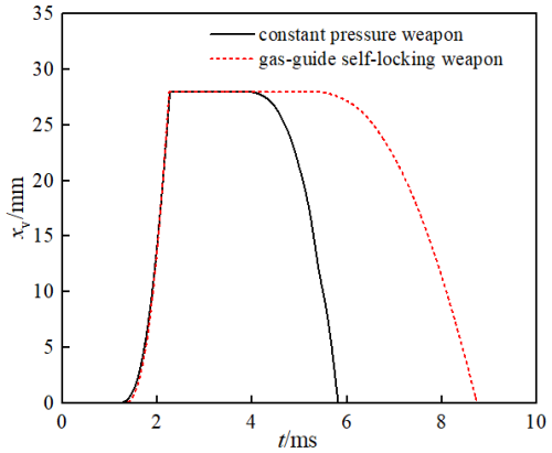
Figure 9 is a schematic diagram of the dual-chamber weapon with a constant-pressure valve. Figures 10 and 11 respectively present a comparison of the injection duration and the recoil impulse during the firing process for the dual-chamber gas-guide self-locking controlled weapon and the dual-chamber weapon with a constant-pressure valve under simulation conditions. According to Fig. 10, although the opening of the rear spray channel of the dual-chamber gas-guide self-locking controlled weapon is controlled jointly by the locking pin and the valve, resulting in a certain delay compared to the dual-chamber fixed-pressure weapon, due to the fact that the starting pressure of the locking pin and the valve in the gas self-locking device is much lower than that of the fixed-pressure valve, the opening time of the rear spray channel of the dual-chamber gas-guide self-locking controlled weapon does not lag significantly behind that of the dual-chamber fixed-pressure weapon – only 0.174 ms. However, under the control of the gas self-locking device, the dual-chamber gas-guide self-locking controlled weapon has a significantly longer rear jet duration than the dual-chamber constant-pressure weapon, with a rear jet duration of 4.682 ms for the constant-pressure weapon and 7.434 ms for the gas-guide self-locking controlled weapon – an increase of 2.752 ms.
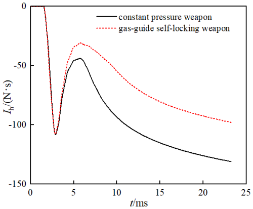
According to Fig. 11, at around 2.889 ms, the recoil impulses of the gas-guide self-locking controlled weapon and the constant-pressure weapon (the direction of the recoil impulse is positive in the direction of the projectile motion, and the recoil impulses mentioned in this section are all absolute values) reach maximum values of 107.74 and 108.15 N s, respectively. Before 3.873 ms, since the rear spray channels of the two weapons open almost simultaneously, the trend of change in the recoil impulse is the same, and the values are similar; after 3.873 ms, the rear spray channel of the constant-pressure weapon in the dual chamber begins to close, the trend of change in the recoil impulse of the two weapons begins to show a more significant difference, and as the rear spray channel of the constant-pressure weapon gradually closes, the difference in the magnitude of the recoil impulses of the two weapons becomes greater. At 5.819 ms, the rear spray channel of the constant-pressure weapon is completely closed; at this time, the remaining powder gas in the chamber of the constant-pressure weapon can only be discharged from the muzzle, so in a period of time thereafter, the magnitude of the recoil impulse of the constant-pressure weapon will show a rapid increasing trend, and the rate of increase is significantly greater than that of the gas-guide self-locking controlled weapon. The back spray channel of the gas-guide self-locking controlled weapon is completely closed at 8.745 ms; thereafter, the powder gas in the chambers of both weapons can only be discharged from the muzzle. Until the end of the after-effect period, the final recoil impulses of the gas-guide self-locking controlled weapon and the constant-pressure weapon are 97.88 and 138.53 N s, respectively, and the recoil reduction efficiencies are 76.72 % and 82.29 %, respectively. In summary, by analyzing the two weapons, under the same conditions of charge and other parameters, compared with the constant-pressure weapon in the dual chamber, the obvious feature of the gas-guide self-locking controlled weapon lies in its ability to prolong the duration of rear spray, thereby ensuring that the initial velocity of the projectile does not decrease, allowing more powder gas inside the chamber to be sprayed out, further reducing the recoil impulse of the weapon and increasing the recoil reduction efficiency.
5.7 Influence of starting pressure of secondary valve piston on weapon performance
The starting pressure of the piston has an important influence on the ballistic performance of the dual-chamber second-stage valve weapon. The greater the starting pressure of piston 1, the later the opening time of the rear jet passage, because a large amount of powder gas generated by the rapid burning of powder particles in the rear chamber cannot be discharged from the nozzle in time, resulting in a rapid increase of pressure inside the bore, which may occur under extreme conditions. Similarly, the greater the starting pressure of piston 2, the later the opening time of the nozzle will be delayed. In addition, piston 2 also controls the closing time of the nozzle. In short, the greater the starting pressure of pistons 1 and 2, the later the rear jet passage will open and the earlier it will close. The shorter the total time the nozzle is open, the lower the recoil reduction efficiency of the weapon.
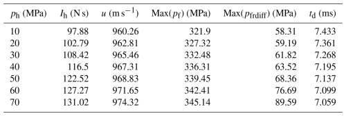
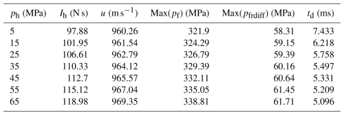
As can be seen from Table 3, the integrated weapon-firing performance decreased significantly with the increase of locking pin activation pressure. Among them, the recoil impulse increases from 97.88 to 131.02 N s, the projectile muzzle velocity increases from 960.26 to 974.32 m s−1, the maximum chamber pressure increases from 321.9 to 345.14 MPa, the pressure difference between the front and rear chambers increases from 58.31 to 89.59 MPa, and the after-spray channel opening time decreases from 7.433 to 7.059 ms. Increasing the activation pressure of the locking pin delays the activation time of the locking pin, which in turn delays the opening time of the rear spray channel. The gunpowder gas generated by the combustion of gunpowder in the rear chamber is not ejected from the rear spray channel in time and accumulates in large quantities, resulting in a rapid increase in the chamber pressure in the rear chamber and an increase in the pressure difference between the front and rear chambers. During this period, the inflow of gunpowder gas from the rear chamber to the front chamber increases, resulting in the increase of the peak chamber pressure and the initial velocity of the projectile in the front chamber. From the conservation of mass, it can be seen that the more gunpowder gas flows into the front chamber from the rear chamber, the less gunpowder gas is ejected from the nozzle and the lower the recoil reduction efficiency.
As can be seen from Table 4, the combined weapon-firing performance decreases equally significantly with the increase in valve activation pressure. Among them, the recoil impulse increases from 97.88 to 118.98 N s, the initial velocity of the projectile increases from 960.26 to 969.35 m s−1, the maximum chamber pressure increases from 321.90 to 338.81 MPa, the pressure difference between the front and rear chambers increases from 58.31 to 61.71 MPa, and the total time for the opening of the rear spray channel decreases from 7.433 to 5.096 ms. The larger the valve startup pressure, the smaller the motion speed during startup and the longer the duration from the start of opening to the complete opening of the rear spray channel. This results in the reduction of the amount of gunpowder gas flowing into the nozzle in the rear chamber within the same time and the reduction of the counterthrust generated by the rear spray of the gunpowder gas. In addition, increasing the valve starting pressure, the valve reset pressure will increase accordingly, resulting in the valve reply earlier, the rear spray channel closing earlier, the effective recoil reduction time of the weapon shortening significantly, and the recoil reduction performance decreasing significantly. Although the gunpowder gas in the rear chamber has flowed into the nozzle during the opening process of the nozzle, the opening speed of the nozzle is slower at the beginning, and the gunpowder gas flowing from the rear chamber into the front chamber is more, resulting in a small increase in the chamber pressure and projectile velocity in the front chamber.
In this paper, to consider the coupling effect of powder gas in the front chamber, rear chamber, fire channel, piston chamber, and lateral rear jet nozzle, a mathematical model of dual-chamber gas-guide self-locking control for reducing recoil in the weapon-firing process was established using two-phase flow theory. The flow field distribution characteristics in the front chamber, rear chamber, piston chamber, and lateral rear jet nozzle of the weapon, as well as the motion processes of the projectile, locking pin, and valve piston in the gas-guide self-locking device, were obtained. The influence of the starting pressure of the gas-guide self-locking device and the size of the fire channel on the weapon performance were analyzed. The following conclusions are drawn:
-
The working mechanism of the dual-chamber gas-guide self-locking control rear spray weapon is revealed. The new optimized design of the locking-pin-controlled rear spray increases the post-spray duration from 4.682 to 7.434 ms, extending it by 58.78 %, and the total post-spray impulse rises from 414.12 to 454.77 N s, further increasing the recoil reduction efficiency to 82.29 %.
-
By analyzing the movement process of the locking pin and valve piston in the air-guided self-locking device, it was found that the locking pin activation pressure and valve activation pressure have a large influence on the recoil reduction efficiency, and these parameters need to be matched reasonably. It is verified that the air-guided self-locking, which controls the opening and closing of the rear spray channel, is able to complete the reset in the weapon-firing cycle, and will not affect the continuous firing of the weapon; the locking pin spring-valve realizes the precise control of the high-pressure opening of the rear spray channel and the low-pressure reset, which makes the structure of this device of better practical value.
-
The dual-chamber mutual flow model developed in this paper can well characterize the transient flow of powder gases inside a dual-chamber rear spray weapon and can be applied to the internal ballistic study of such weapons.
| A | Cross-section area of the barrel |
| Av1 | Cross-sectional area of piston 1 |
| Av2 | Cross-sectional area of piston 2 |
| dv1 | Diameter of piston 1 |
| dv2 | Diameter of piston 2 |
| Energy of powder gas passing through the fire hole exchanged between the rear chamber and the front chamber | |
| egb | Specific internal energy of the gas phase in the rear chamber |
| eim | Energy per unit mass of propellant gas flowing from the rear chamber into the piston chamber |
| eio | Energy per unit mass of propellant gas flowing from the piston chamber into the lateral after-burning channel |
| eiv | Specific internal energies of the gas phase at the vent hole |
| eip | Specific internal energies of the solid phase at the vent hole |
| ep | Chemical energy of the solid phase |
| evt | Specific internal energy of the propellant gas at the inlet of the lateral after-burning channel |
| F01 | Spring pre-load force of piston 1 |
| F02 | Spring pre-load force of piston 2 |
| fsb | Interphase resistance per unit volume between gas and solid phases in the rear chamber |
| Fv0 | Initial volume of the piston chamber |
| Hign | Enthalpy of the ignition powder |
| I | Gas-solid flow between the rear chamber and the front chamber |
| J | Gas-solid flow between the rear chamber and the piston chamber |
| K | Gas-solid flow between the rear chamber and the nozzle |
| k | Specific heat ratio of the powder gas |
| kv1 | Spring stiffness of piston 1 |
| kv2 | Spring stiffness of piston 2 |
| mcb | Generation rate of powder gas per unit volume |
| mg′ | Mass of the powder gas |
| mp′ | Mass of the solid particles |
| miv | Unit volume mass flow rate of the gas phase flowing from the vent hole inside the rear chamber into the piston chamber |
| mip | Unit volume mass flow rate of the solid phase flowing from the vent hole inside the rear chamber into the piston chamber |
| mign | Generation rate of ignition powder gas from different ignition components |
| mit | Unit volume mass flow rate of propellant gas flowing from the piston chamber into the lateral after-burning channel |
| mv1 | Mass of piston 1 |
| mv2 | Mass of piston 2 |
| nd | Number of computational grids corresponding to the fire hole in the chamber |
| nc | Number of differential mesh cells corresponding to the gas-guide hole in the chamber |
| pa | Atmospheric pressure |
| pb | Gas-phase pressure in the rear chamber |
| pb′ | Pressure of the powder gas at the fire hole in the rear chamber |
| pf′ | Pressure of the powder gas at the fire hole in the front chamber |
| piv | Pressure at the vent hole |
| pv | Pressure of the propellant gas in the piston chamber |
| pvt | Gas pressure at the inlet of the lateral after-burning channel |
| pbv | Pressure at the gas-guide hole of the body tube in the rear chamber |
| Qs | Heat exchange per unit surface area between the gas and solid phases in the rear chamber |
| Qv | Heat dissipated in the piston chamber |
| rt | Radius of lateral back spray inlet |
| rv | Radius of the piston |
| R | Gas constant |
| Rb | Force between the powder particles |
| S | Cross-sectional area of the gas-guide hole |
| Sd | Cross-sectional area of the fire hole |
| St | Open area of the back spray channel |
| Tv | Temperature of the gas in the piston chamber |
| Ta | Temperature of the gas in the external environment |
| uiv | Velocity of the powder gas entering the piston chamber from the vent hole inside the rear chamber |
| uip | Velocity of the powder particles entering the piston chamber from the vent hole inside the rear chamber |
| ug′ | Velocity of powder gas passing through the fire hole |
| up′ | Velocity of solid particles passing through the fire hole |
| ugb | Gas-phase velocity in the rear chamber |
| uign | Velocity of the ignition powder |
| upb | Solid-phase velocity in the rear chamber |
| uvt | Specific velocity of the propellant gas at the inlet of the lateral after-burning channel |
| μb | Flow coefficient of the lateral back nozzle inlet |
| vv1 | Velocity of piston 1 |
| vv2 | Velocity of piston 2 |
| Vv0 | Initial volume of the piston chamber |
| xv1 | Displacement of piston 1 |
| xv2 | Displacement of piston 2 |
| xv | Displacement of the piston |
| xv0 | Initial displacement of the piston |
| γ | Adiabatic index |
| Δx | Length of the grid in the chamber |
| Δxc | Grid length used in the differential calculation |
| ζ | Critical pressure ratio |
| θ | Velocity ratio of the solid phase to the gas phase |
| ρgb | Density of the gas phase flowing through the rear chamber |
| ρgb′ | Density of the powder gas at the fire hole in the rear chamber |
| ρgf′ | Density of the powder gas at the fire hole in the front chamber |
| ρp | Density of solid particles |
| ρv | Density of the propellant gas in the piston chamber |
| ρvt | Gas density at the inlet of the lateral after-burning channel |
| ρiv | Densities of the powder gas phase flowing from the vent hole in the rear chamber into the piston chamber |
| ρip | Densities of the powder solid phase flowing from the vent hole in the rear chamber into the piston chamber |
| ρbv | Density of the propellant gas at the gas-guide hole in the rear chamber |
| φb | Void fraction at the fire hole in the rear chamber |
| φf | Void fraction at the fire hole in the front chamber |
| ϕb | Gas-phase void fraction in the rear chamber |
| ϕbv | Void fraction at the gas-guide hole in the rear chamber |
| αc | Heat transfer coefficient |
The datasets used and/or analyzed during the current study are available from the corresponding author on reasonable request.
WL: conceptualization, methodology, software, and writing (original draft). MQ: conceptualization, methodology, and writing (review and editing). WX: software and writing (review and editing). YT: software and writing (review and editing). FG: writing (review and editing). JS: writing (review and editing).
The contact author has declared that none of the authors has any competing interests.
Publisher's note: Copernicus Publications remains neutral with regard to jurisdictional claims made in the text, published maps, institutional affiliations, or any other geographical representation in this paper. While Copernicus Publications makes every effort to include appropriate place names, the final responsibility lies with the authors. Views expressed in the text are those of the authors and do not necessarily reflect the views of the publisher.
This research has been supported by the National Natural Science Foundation of China (grant nos. 12072161, 52475108, and 51376090).
This paper was edited by Liangliang Cheng and reviewed by four anonymous referees.
Bougamra, A. and Lu, H. L.: Determination of pressure profile during closed-vessel test through computational fluid dynamics simulation, Journal of Thermal Science and Engineering Applications, 8, 1–6, https://doi.org/10.1115/1.4031930, 2016.
Cao, R. D. and Zhang, X. B.: Design optimization for a launching system with novel structure, Defence Technology, 15, 680–689, https://doi.org/10.1016/j.dt.2019.08.005, 2019.
Cheng, C. and Zhang, X. B.: Two-dimensional numerical simulation on two-phase flow interior ballistic performance of a guided projectile, Journal of China Ordnance, 36, 58–63, https://doi.org/10.3969/j.issn.1000-1093.2015.01.009, 2015.
Cheng, C. and Zhang, X. B.: Numerical modeling and investigation of two-phase reactive flow in a high-low pressure chambers system, Applied Thermal Engineering, 99, 244–252, https://doi.org/10.1016/j.applthermaleng.2016.01.046, 2016.
Cheng, C. and Zhang, X. B.: Numerical investigation of two-phase reactive flow with two moving boundaries in a two-stage combustion system, Applied Thermal Engineering, 156, 422–431, https://doi.org/10.1016/j.applthermaleng.2019.04.061, 2019a.
Cheng, C. and Zhang, X. B.: Parallel numerical simulation on three-dimensional two-phase flow of interior ballistic trajectory, Journal of China Ordnance, 40, 769–776, https://doi.org/10.3969/j.issn.1000-1093.2019.04.012, 2019b.
Chen, Y.: Research on key technology of nozzle airflow reverse thrust recoil reduction weapon system, MS, Nanjing University of Science and Technology, Nanjing, China, 2 pp., 2010.
Hu, C. and Zhang, X. B.: Performance variation of a transient dynamic fluid-structure interaction system in different life stages and methods for maintaining the performance, Applied Thermal Engineering, 130, 1012–1021, https://doi.org/10.1016/j.applthermaleng.2017.11.075, 2018.
Li, Z. J., Qiu, M., and Song, J.: Numerical simulation of the two-phase flow of a constant-pressure rear-spray low recoil weapon with two chambers, 1st International Conference on Fluid Dynamics and Computational Science, 2022, Chengdu, 0272, https://doi.org/10.1088/1742-6596/2441/1/012007, 2022.
Liang, D. F., Wang, X. L., and Falconer, X. L.: Solving the depth-integrated solute transport equation with a TVD-MacCormack scheme, Environmental Modelling & Software,25, 1619–1629, https://doi.org/10.1016/j.envsoft.2010.06.008, 2007.
Liao, Z. Q. and Qiu, M.: Gas dynamics of automatic weapons, National Defense Industry Press, Beijing, 31–32, ISBN: 9787118106084, 2015.
Ma, L. X., Qiu, M., and Song, J.: Study on micro recoil mechanism of the weapon with a nozzle and two chambers separated by a partition, Proceedings of 2021 International Conference on Fluid and Chemical Engineering, ICFCE 2021, 84–90, https://doi.org/10.1088/1742-6596/2097/1/012009, 2021.
Menshov, I. S., Nemtsev, M. Y., and Semenov, I. V.: Numerical modeling of wave processes accompanying combustion of in homogeneously distributed composite propellant, Computational Mathematics and Mathematical Physics, 59, 1528–1541, https://doi.org/10.1134/S0965542519090148, 2019.
Qiu, M., Si, P., and Song, J.: Recoil reduction method of gun with side to rear jet controlled by piston motion, Symmetry-Basel, 13, 396, https://doi.org/10.3390/sym13030396, 2021.
Qiu, M., Song, J., and Liao, Z. Q.: New principles and technologies of weapon powder gas energy utilization, National Defense Industry Press, Beijing, 12–13, ISBN: 978-7-118-12779-9, 2022.
Qiu, M., Guo, F., and Song, J.: Recoil reduction design of gas-controlled side-jet gun based on bifurcated two-phase flow model, Journal of Mechanical Science and Technology, 37, 1845–1857, https://doi.org/10.1007/s12206-023-0323-y, 2023.
Song, J., Liao, Z. Q., and Li, H. Q.: Study on reducing recoil mechanism of jet gas with laval nozzles with double chamber, Journal of Harbin Institute of Technology, 50, 79–87, https://doi.org/10.11918/j.issn.0367-6234.201708060, 2018a.
Song, J., Qiu, M., and Liao, Z. Q.: Modeling of two jet gas devices and its firing efficiency comparison, Transactions of Beijing Institute of Technology, 38, 585–592, https://doi.org/10.15918/j.tbit1001-0645.2018.06.006, 2018b.
Weng, C. S. and Wang, H.: Computational interior ballistics, National Defense Industry Press, Beijing, 71–77, ISBN: 7118042013, 2006.
Zha, J. P. and Chen, Y. H.: Numerical simulation of helicopter simulator bench under action of aircraft cannon shock wave, Chinese Journal of Applied Mechanics, 39, 627–632, https://doi.org/10.11776/j.issn.1000-4939.2022.04.003, 2022.
Zhang, F.: Expansion wave artillery firing principle and its application in conventional structure guns, MS, Nanjing University of Science and Technology, Nanjing, China, 2 pp., 2007.
- Abstract
- Introduction
- Mechanism of dispersed charging gas-guide self-locking control post-spraying
- A two-phase flow model for the launch process of a dual-chamber gas-guide self-locking controlled rear spray weapon
- Mathematical solution method
- Results and discussions
- Conclusion
- Appendix A: nomenclature
- Data availability
- Author contributions
- Competing interests
- Disclaimer
- Financial support
- Review statement
- References


