the Creative Commons Attribution 4.0 License.
the Creative Commons Attribution 4.0 License.
 | 28 Oct 2025
Adaptive disturbance rejection control of magnetorheological seat suspension systems based on adaptive neuro-fuzzy inference system inverse modeling and improved crow search optimization
Xinkun Yang
Bo Guo
Yihan Huang
Weiqi Chen
Operators of agricultural vehicles are frequently exposed to prolonged vibrations, which pose serious health risks and degrade operational performance. Magnetorheological (MR) dampers have been increasingly adopted in seat suspension systems owing to their low power consumption and fast response. However, their inherent nonlinear hysteresis and time-varying dynamics significantly challenge the effectiveness of conventional control strategies. To overcome these limitations, this study proposes a hybrid ICSA-ANFIS-ADRC control framework that integrates an improved crow search algorithm (ICSA)-optimized adaptive neuro-fuzzy inference system (ANFIS) with an active disturbance rejection control (ADRC) strategy. The nonlinear behavior of the MR damper is first modeled using an improved Bouc–Wen approach. An inverse model is then constructed through ICSA-ANFIS training to predict the control current accurately. This inverse model is subsequently embedded within the ADRC framework to enable real-time multi-modal damping force regulation. Numerical simulations based on a 3-degrees-of-freedom seat suspension model demonstrate that the proposed method significantly outperforms conventional ANFIS-ADRC and CSA-ANFIS-ADRC controllers. Specifically, up to 32.9 % reduction in vertical vibration acceleration is achieved, while robust control performance is maintained under both random and shock road conditions. The inverse model attains a root mean square prediction error below 0.15 for control current, verifying its accuracy and adaptability. The proposed ICSA-ANFIS-ADRC control scheme thus provides a promising solution for intelligent seat suspension systems, effectively mitigating low-frequency resonance and enhancing ride comfort in agricultural vehicles.
- Article
(7610 KB) - Full-text XML
- BibTeX
- EndNote


Operators of agricultural vehicles, such as tractors and specialized machinery, are frequently subjected to sustained vibrations caused by uneven terrain. Prolonged exposure to such vibrations has been shown to induce adverse health effects, including fatigue, reduced alertness, impaired driving performance, and long-term musculoskeletal disorders such as lower back pain and spinal discomfort. These health risks underscore the importance of effective seat suspension systems to improve both safety and ride comfort (Lecocq et al., 2022; Schneider et al., 2023; de la Hoz-Torres et al., 2021; Barač et al., 2025). In response to these risks, multiple seat suspension technologies have been proposed, encompassing passive (Samaroo et al., 2025; Stein et al., 2009), semi-active (Zhao et al., 2023; Liu et al., 2019), and active suspension systems (Maciejewski et al., 2023; Gheibollahi et al., 2024; Zhao et al., 2025). Despite their effectiveness, active suspensions are rarely adopted in agricultural vehicles owing to their complexity and high cost, which conflict with the sector's cost-sensitive design constraints. As a result, passive and semi-active seat suspension systems are more commonly employed (Zhao et al., 2025). Passive systems, while historically dominant due to their simplicity and reliability, lack adaptability to variable road conditions and complex excitations, limiting their effectiveness in improving ride comfort. Semi-active suspensions have thus emerged as a viable compromise, combining structural simplicity with real-time adaptability (Ferhath and Kasi, 2024; Lee and Oh, 2025).
As core elements in semi-active control systems, magnetorheological (MR) dampers exhibit strong potential for attenuating seat vibrations and mitigating whole-body vibrational exposure in vehicle occupants. With growing demand for enhanced seating comfort, the role of seat suspension systems in ensuring both ride comfort and safety has garnered substantial research interest (Hua, 2025; Gad et al., 2025). These systems utilize intelligent control strategies to dynamically modulate damping force in response to varying road and operational conditions, thereby enhancing ride comfort and handling stability without the high energy demands of active suspension systems. However, under shear-mode operation, MR dampers exhibit asymmetric hysteresis in their force–velocity characteristics, which introduces nonlinearities and causes time lag effects when conventional control methods are applied. Although methods such as active disturbance rejection control (ADRC) can partially address external disturbances and time delays, their reliance on fixed controller parameters limits adaptability under varying conditions (Wang et al., 2024; Yaghoubi and Ghanbarzadeh, 2024). Consequently, real-time optimization of key controller parameters has become a pivotal challenge in improving the damping performance of MR-based suspension systems.
Recent advancements have explored two primary directions for integrating intelligent optimization algorithms into control systems: (1) improving swarm intelligence optimization algorithms (e.g., particle swarm optimization, PSO) to prevent control performance degradation and (2) modifying conventional controllers to better accommodate the nonlinear and time-varying characteristics of MR dampers. For instance, Guo et al. (2024) developed an enhanced Jiles–Atherton hysteresis model optimized by an improved PSO algorithm, which significantly increased parameter identification accuracy (error was reduced by 40.2 %) and improved the prediction of damping force. Similarly, Zhang et al. (2024) applied NSGA-II to optimize the structural parameters of a conical-channel MR damper, demonstrating improved yaw stability under extreme maneuvers. Li et al. (2024) proposed a sliding-mode control strategy enhanced by an extended African vulture optimization algorithm (EAVOA) to suppress vibrations in semi-active suspension systems under stochastic road conditions. Population initialization was optimized via logistic chaotic mapping, and a nonlinear disturbance-based hunger value adjustment strategy was adopted to efficiently optimize control parameters. Road tests on B- and D-grade surfaces showed a maximum reduction of 42.5 % in vehicle body acceleration and a 25.9 % decrease in suspension dynamic travel, with smooth damping force response, providing a new approach to precise control of MR dampers. Guo et al. (2025) introduced a sensitivity analysis method based on PSO to identify parameters in MR damper dynamic models. The effects of particle number (N), iteration count (T), and learning factors () on the fitting accuracy of the hyperbolic tangent model were systematically quantified, and the optimal parameter set was determined through orthogonal experiments. As a result, the root mean square error (RMSE) of damping force prediction was reduced to 0.013 under the 0.8 A condition. Experimental results showed strong agreement between simulation and measured data, establishing a high-accuracy modeling foundation for semi-active suspension control. Zhao et al. (2024) proposed an adaptive neural-network-based backstepping control strategy to address uncertainties in sprung mass and time-varying input delays in MR semi-active air suspension systems. The nonlinear dynamics of the air spring were precisely modeled using a radial basis function neural network (RBFNN), and the sprung mass was continuously updated by a projection-constrained estimator. A Lyapunov–Krasovskii functional-based delay compensator was designed to suppress a 32.4 ms actuator delay. Under conditions involving step changes in sprung mass and variable delay, the vehicle body acceleration was reduced by 16.2 %, and the suspension dynamic deflection was reduced by 5.9 %, offering a viable solution for high-comfort suspension systems. Ji et al. (2024) proposed a variable universe fuzzy Proportional–Integral–Derivative (PID) control strategy based on a dynamic adjustment function (VUFP-DAF) to address the limitations of expert-dependent fuzzy rules and poor adaptability of fixed scaling factors in Continuous Damping Control (CDC) damper-based semi-active suspension systems. A dynamic scaling factor, using system error e(t) and its rate of change ec(t) as inputs, was designed for real-time universe adaptation, and system stability was rigorously proven. Verification on B- and C-grade random roads and bump surfaces showed a maximum reduction of 53.88 % in vertical acceleration and 45.65 % in suspension deflection, significantly outperforming conventional fuzzy PID and fixed-factor methods, offering a robust control solution under complex conditions. Zhan et al. (2025) addressed the adaptability challenges of MR semi-active suspension systems under strongly nonlinear and time-varying conditions by proposing a proximal policy optimization algorithm integrated with neural ordinary differential equations (PPO-NODEs). The improved Bouc–Wen model was used to accurately characterize damper dynamics, and an actor network enhanced by NODEs was designed to model continuous suspension state evolution. Simulations on C-grade random roads showed a 30.22 % reduction in vehicle acceleration compared to passive suspensions, while bench experiments confirmed an acceleration reduction of up to 77.51 %. The algorithm substantially improved control generalization under complex conditions, offering a new solution for intelligent vehicle suspension systems.
Despite these advances, most existing studies focus on refining controller structures or incorporating optimization algorithms for offline parameter tuning, whereas few works have addressed the real-time optimization of controller outputs in conjunction with adaptive control strategies. This gap limits the applicability of existing methods under complex and rapidly changing road conditions typically encountered by agricultural vehicles. To address these challenges, the present study makes the following contributions:
-
An improved crow search algorithm (ICSA) is developed by introducing a triangular probability distribution mechanism, which enhances population diversity and accelerates convergence to global optima.
-
A dynamic adaptive neuro-fuzzy inference system (ANFIS) structure with time-varying membership functions is constructed, enabling real-time adjustment of the damping control strategy and reducing the influence of the MR damper's time-varying properties.
-
A hybrid ICSA-ANFIS-ADRC control framework is proposed, where a Kalman filter is embedded in the ADRC observation layer to suppress noise, and the control signals are dynamically optimized by the ICSA-ANFIS inverse model. This integration achieves multi-modal damping control and robust vibration suppression across diverse operating conditions.
In summary, the proposed method not only improves modeling accuracy and control adaptability but also demonstrates superior robustness in vibration isolation compared with conventional ANFIS-ADRC and CSA-ANFIS-ADRC strategies.
2.1 Tractor seat suspension model
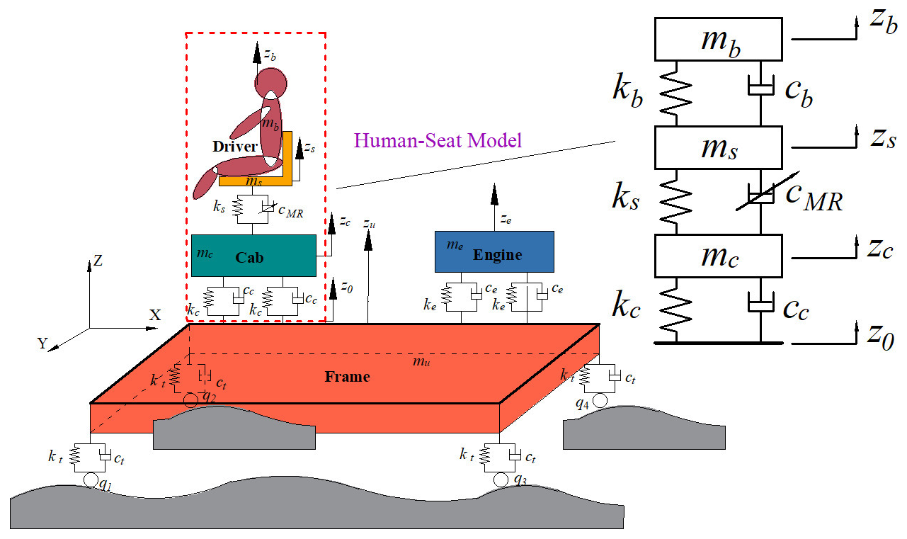
Figure 1 illustrates a 3-degrees-of-freedom (3-DOF) lumped-parameter model designed to characterize the dynamic behavior of the seat suspension system equipped with an MR damper. In this model, mb and ms represent the masses of the human body and the seat, respectively; kb and cb correspond to the stiffness and damping of the human body; ks and cMR denote the stiffness and equivalent damping of the seat suspension and MR damper; and zb, zs, and z0 represent the displacements of the human body, the seat, and the base excitation, respectively.
Based on Newtonian mechanics, the dynamic equations governing the 3-DOF seat suspension system are formulated as follows:
where FMR represents the damping force of the MR damper of the seat.
To facilitate controller design and system simulation, the equations of motion are converted into a state space representation, as shown in Eq. (2):
where the state variable , the input variable , and the output variable . The equation of state of the system after substitution is given by Eq. (3).
2.2 Improved Bouc–Wen model for MR dampers
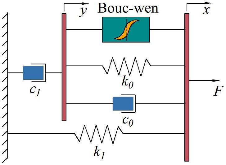
Accurate mathematical modeling of MR dampers is essential for ensuring realistic system dynamics simulations. The Bouc–Wen model is widely adopted for its ability to characterize the nonlinear hysteresis behavior of MR dampers, particularly the relationship between relative displacement, velocity, and damping force. Thus, it has gained widespread application. While the conventional Bouc–Wen model comprises a spring, a viscous damper, and a hysteresis element arranged in parallel, an improved version introduces an additional spring and damper to enhance modeling accuracy and flexibility. In this study, the improved Bouc–Wen model is employed to represent the forward dynamic behavior of the MR damper, capturing its nonlinear and rate-dependent response characteristics, and its structure is shown in Fig. 2.
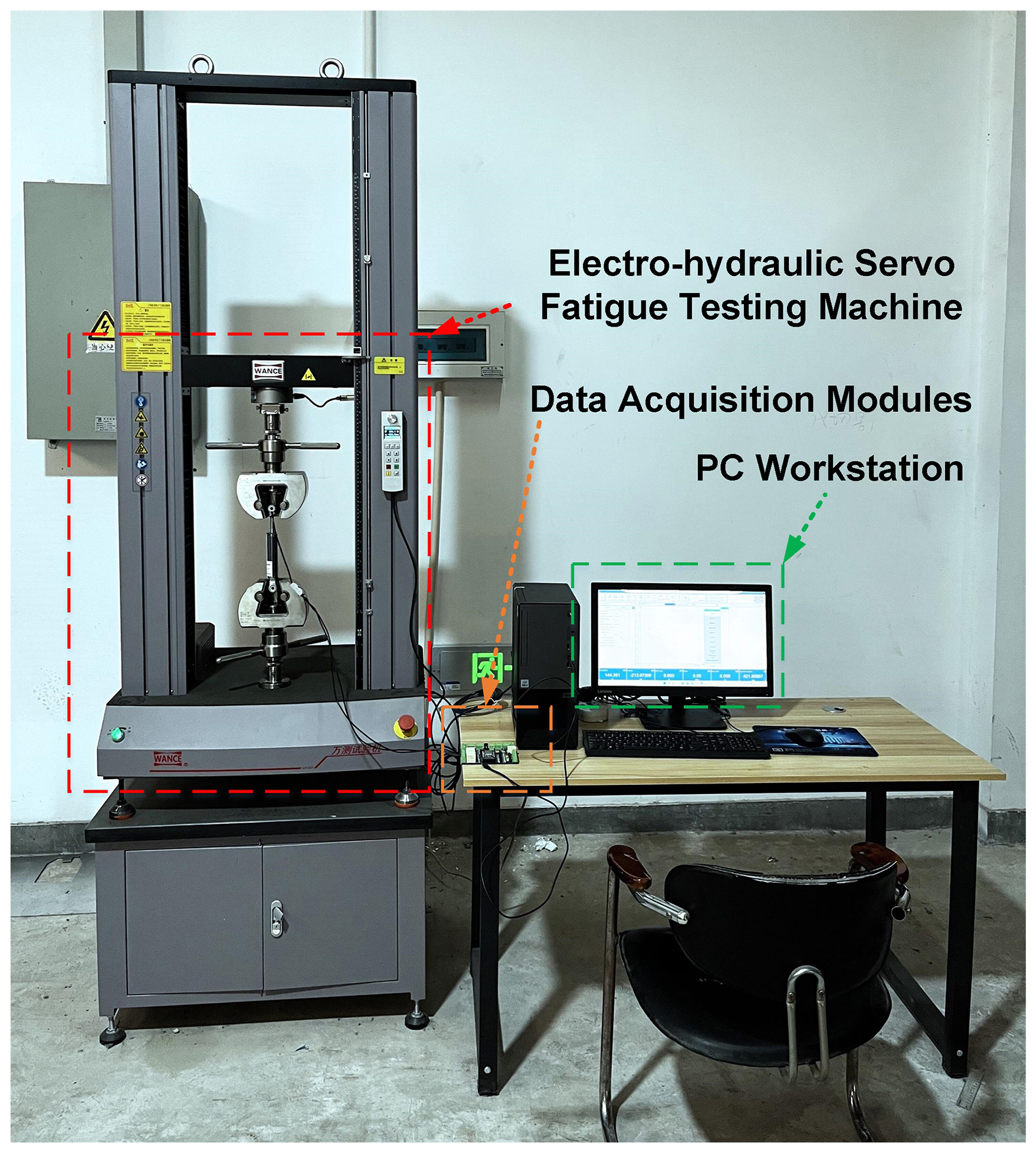
To evaluate the force–velocity and force–displacement characteristics of the MR damper, experiments were conducted using an electro-hydraulic servo fatigue testing machine (WANGCE, China), as shown in Fig. 3. The test system consisted of a servo actuator, a load cell, displacement and velocity sensors, a programmable current driver, and a data acquisition module connected to a workstation. The actuator applied sinusoidal excitations with a displacement amplitude of 15 mm at a frequency of 2 Hz, while the control current was varied from 0 to 1.5 A in increments of 0.25 A. Displacement and velocity signals of the piston rod were recorded using high-precision sensors, while the input current signal was simultaneously monitored through the driver unit. The damping force was directly measured by a calibrated load cell attached in series with the damper. All signals were sampled at a frequency of 500 Hz, filtered to remove high-frequency noise, and subsequently processed in MATLAB/Simulink for parameter identification. This procedure provided a comprehensive dataset of piston displacement, velocity, current, and force responses, which was then used to calibrate the improved Bouc–Wen model through the Simulink Design Optimization toolbox.
The improved Bouc–Wen model can effectively fit the relationship between the output damping force of the MR damper and the relative displacement and velocity of the piston. The damping force is expressed as follows:
where F is the damping force of the MR damper, c0 and c1 are the viscous damping coefficients; k0 and k1 are the stiffness coefficient; α is the scaling parameter of the hysteresis force in the damping force; x0 is the relative displacement of the equilibrium position offset; z is the hysteresis variable; x is the total displacement of the MR damper; y is the hysteresis displacement of c1; n is the rounding coefficient; and γ, β, and A are the parameters used to adjust the smoothness of the model and the linear characteristics of the curves from the pre-yielding region to the post-yielding region. Parameters are used to adjust the smoothness of the model and the linear character of the curve from the pre-yield to the post-yield region.
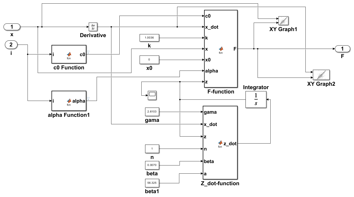
The improved Bouc–Wen model is built in Simulink, and the constructed model can be obtained using Eq. (4), as shown in Fig. 4.
The improved Bouc–Wen model incorporates eight unknown parameters. While conventional identification methods such as genetic algorithms and least squares exist, they often entail computationally intensive procedures. Consequently, this study employs the Simulink Design Optimization toolbox for parameter identification. Measured piston relative displacement, velocity, and current serve as model inputs, with damping force designated as the output. Model predictions are subsequently compared against experimental results.
Following the implementation of the improved Bouc–Wen model in Simulink, parameter calibration was performed utilizing experimental datasets obtained under specified operating conditions: an excitation frequency of 2 Hz, displacement amplitude of 15 mm, and input currents ranging from 0 to 1.5 A. Sensitivity analysis indicated that parameters α and c0 exhibit strong current dependency, while the remaining six parameters remain invariant across different operating states. Through iterative optimization, the current-dependent characteristics of α and c0 were successfully approximated by quadratic polynomial functions, demonstrating close agreement with experimental observations. The finalized parameter identification results, encompassing both current-variant and current-invariant parameters, are comprehensively summarized in Table 1.
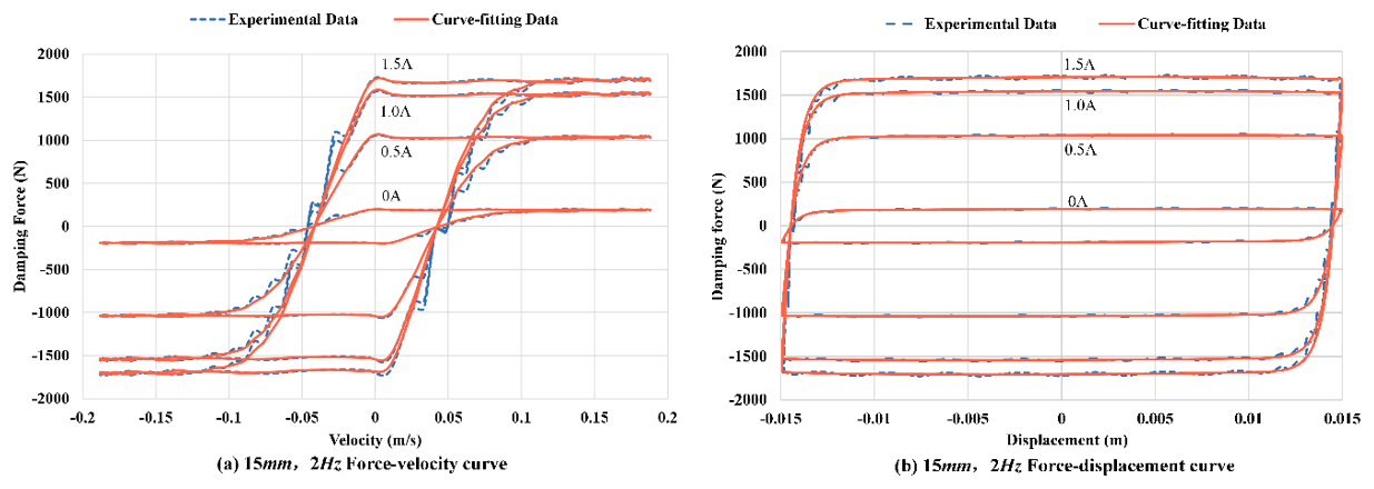
Figure 5Comparison between model simulations and experimental data for MR damper characteristics under 2 Hz excitation.
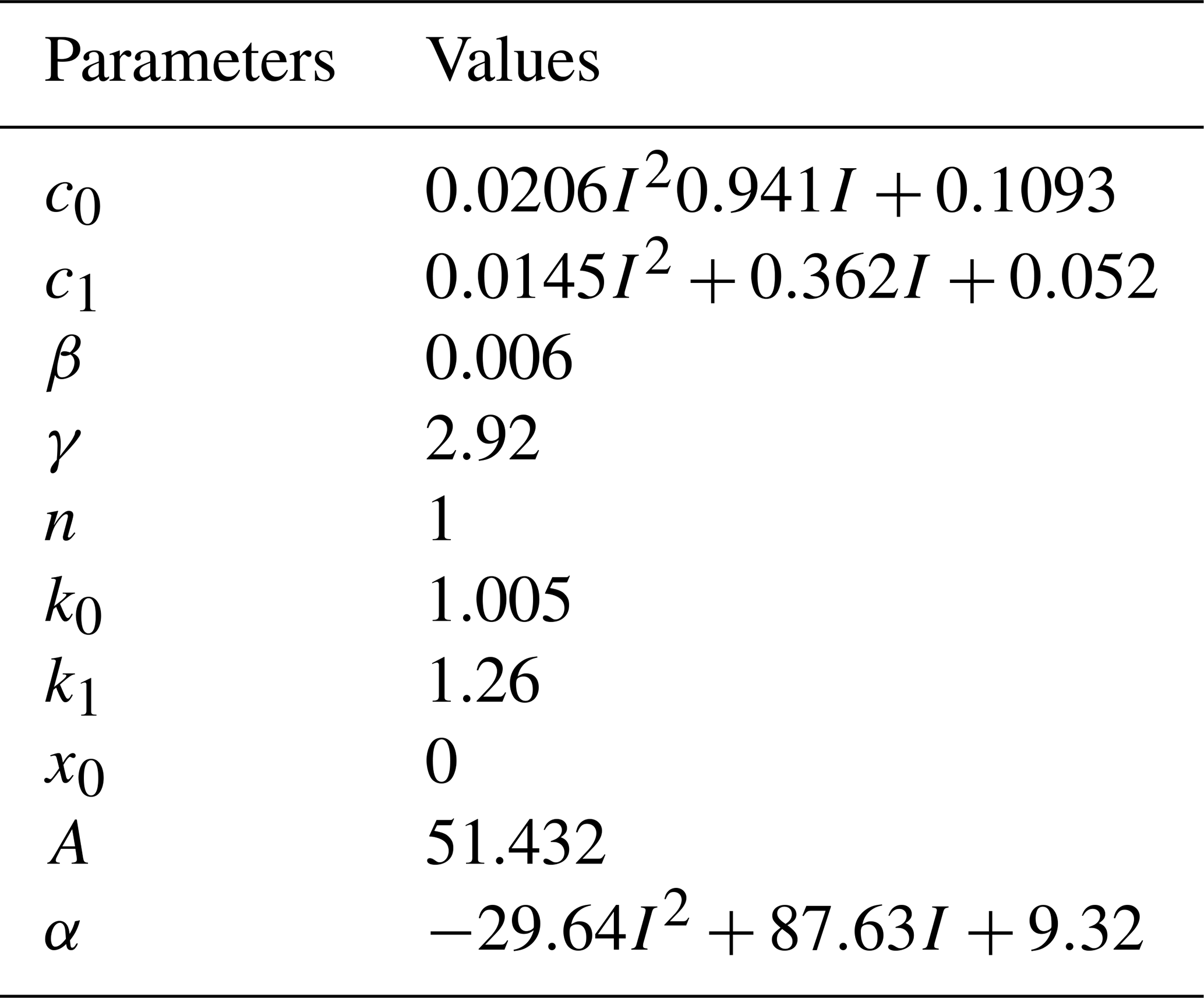
The parameters of the improved Bouc–Wen model were identified using experimental datasets obtained under the specified excitation conditions. A sensitivity analysis was first conducted to determine the dependence of each parameter on the input current. The results indicated that the parameters α and c0 exhibited strong current dependency as they directly influence the scaling of the hysteresis force and the viscous damping characteristics of the MR damper. Consequently, both parameters were expressed as quadratic polynomial functions of the input current, enabling accurate representation of their variation across different operating states. In contrast, the remaining parameters (β, γ, A, k0, k1, x0, n) showed negligible dependence on current and were therefore treated as constants. This hybrid parameterization approach ensures that the improved Bouc–Wen model captures both the current-dependent nonlinear hysteresis effects and the invariant structural characteristics of the MR damper. As a result, the model achieves a high degree of consistency with the experimental measurements, as confirmed in Fig. 5.
Figure 5 illustrates the comparison between the experimental results (solid line) and the model predictions (dashed line). From the above figure, it can be intuitively seen that the curve obtained from the parameter fitting using the improved Bouc–Wen model and the applied Simulink parameter identification is basically consistent with the curve obtained from the damper characteristic test, and the fitting effect is good.
3.1 Standard crow search algorithm and its improvement
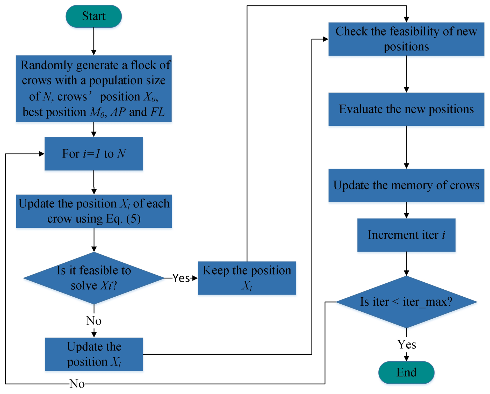
The crow search algorithm (CSA), introduced by Askarzadeh in 2016 (Askarzadeh, 2016), addresses global optimization problems by mimicking the foraging behavior of crows. It is a metaheuristic method characterized by few tunable parameters and strong convergence performance. It is considered to be a novel metaheuristic algorithm, and its process is illustrated in Fig. 6.
Specifically, the detailed procedure of the CSA algorithm is as follows:
-
Step 1. A population of N crows is randomly initialized, with each crow's position and memory location being set to the same value. The initial positions of these crows (i.e., the initial solution set) are denoted as X0= (X1, X2, …, XN), and the memorized best hiding locations of food by the crows are denoted as M0= (M1, M2, …, MN), where M0=X0.
-
Step 2. The position Xi of each crow is updated. The update principle assumes that crow i randomly selects crow j to follow. Two possible outcomes arise. (1) If crow j is unaware of being followed then crow i will move toward j's memorized best food-hiding location Mj. (2) If crow j is aware of being followed, it will intentionally mislead crow i to a random position. The position update strategy is mathematically expressed as
where k denotes the current iteration number; AP and FL represent the awareness probability and flight length, respectively; and rk and rand refer to uniformly distributed random numbers and random sequences within the range [0,1].
-
Step 3. The feasibility of the solution Xi is evaluated. If the updated solution lies within the feasible domain, the update is accepted and replaces the original; otherwise, the original solution is retained.
-
Step 4. The fitness value f of the solution Xi is calculated.
-
Step 5. The food-hiding position Mi is updated. The specific update strategy is expressed as
-
Step 6. Steps 2 to 5 are repeated to iteratively optimize Xi and Mi until the convergence criterion of the algorithm is satisfied. In the standard CSA described above, the crow j being followed in step 2 (i.e., the target crow) is randomly selected. This random selection often prevents many crows from improving their positions, which may cause the algorithm to become trapped in local optima. To address this issue, the standard CSA is improved by introducing a triangular probability distribution strategy to select the target crow (Lin et al., 2021). The triangular probability distribution is expressed as
In each iteration, crows with a probability greater than pt are selected, where pt is calculated as
where rand2 is a uniformly distributed random number in the range [0,1].
The crows selected through this triangular probability method are provided with a greater competitive advantage. One target crow is then randomly selected from this group for tracking, ensuring population diversity within the crow swarm. Furthermore, to enhance the diversity of solutions, a mutation operation is applied to the updated solutions obtained from Eq. (7) (Lin et al., 2021). As an example of this operation, several consecutive elements in the encoding are randomly selected and then reversed to introduce variability.
In the above, C denotes the code segment to be mutated, # represents the inversion mutation operation, ml is the randomly selected mutation length, and sp is the randomly selected starting position of the mutation.
3.2 ANFIS-based inverse modeling of the MR damper using ICSA
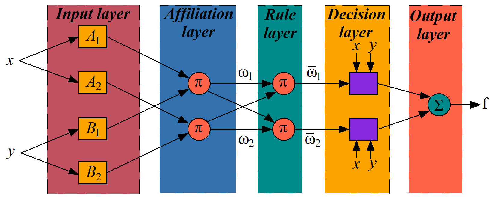
In constructing the ANFIS-based inverse model of the MR damper, the input dimensionality must be carefully selected to avoid the curse of dimensionality. Accordingly, a four-input, single-output architecture is employed (Fig. 7).
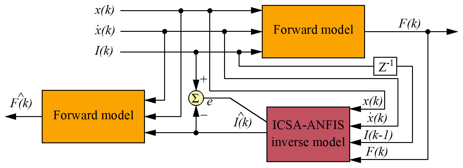
First, the damping force F(k) is calculated using the forward model described in Sect. 2.2 to calculate the damping force F(k) from three inputs: displacement x(k), velocity , and control current I(k). This generates a training dataset comprising x(k), , F(k); the previous current I(k−1); and the present current I(k), of which the first four are used as inputs for training the ANFIS network. The ANFIS structure is optimized using the ICSA (the specific optimization procedure is detailed later in this subsection), enabling the network to accurately output the predicted control current . Once the optimal inverse model of the MR damper has been trained, the forward model is applied again to compute the predicted damping force , thereby enabling further validation of the inverse model's effectiveness, as shown in Fig. 8.
For the ANFIS structure illustrated in Fig. 7, the system output y is given by
where θ is the parameter vector, and A is the coefficient matrix constructed from the input data.
If the four inputs of the ANFIS model are denoted as x1, x2, x3, and x4 then the output of the fourth layer is given by
In Eq. (17), represents a set of consequent parameters, organized as a 20×1 dimensional vector. If Nt training samples are provided, the output vector y and the coefficient matrix A have dimensions of Nt×1 and Nt×20, respectively.
The standard hybrid learning algorithm of ANFIS consists of a combination of the gradient descent method and the least squares estimation (LSE) technique. During each iteration, the system input is first forward propagated using the least squares method to estimate the consequent parameters θe:
Accordingly, the predicted output of the ANFIS, denoted as ye, is given by
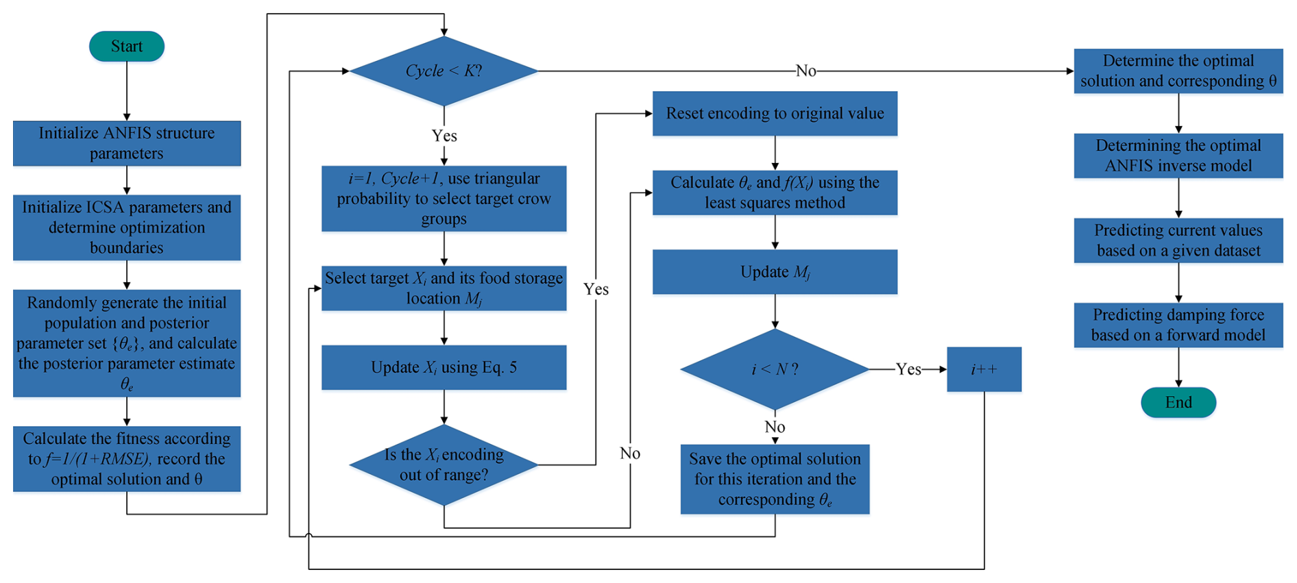
While keeping the estimated consequent parameters θe fixed, the antecedent parameters are optimized using a backpropagation algorithm based on gradient descent in order to derive the solution for the ICSA algorithm. Considering the tendency of the gradient descent method to fall into local optima, the ANFIS model is enhanced using the ICSA approach in this study. Specifically, ICSA is employed to optimize the antecedent parameters, while the least squares method is applied to identify the consequent parameters. The inverse modeling process is summarized in Fig. 9, which outlines the key stages: input selection, membership function definition, ICSA-based optimization, and model validation using forward simulation.
-
Model structure and data preparation.
-
Input selection. The inputs are selected to be displacement x(k), velocity , damping force F(k), and the previous control current I(k−1). The predicted current is used as the output , forming a four-input, single-output ANFIS architecture.
-
Membership function selection. Gaussian membership functions are selected for each input variable. The general form of the Gaussian membership function is expressed as
where ci denotes the center of the membership function, and σi represents its standard deviation. Three Gaussian membership functions are assigned to each input in order to cover the entire range of the input variables. The total number of antecedent parameters is 4 inputs ×3 functions ×2 parameters =24 antecedent parameters. The consequent parameters are defined as a linear combination of , resulting in a total of 64 consequent parameters.
-
-
ICSA-ANFIS optimization.
-
Parameter encoding and initialization. The antecedent parameters (ci, σi) and consequent parameters (pi, qi, ri, si, ti) are concatenated into a real-valued encoded vector. The ICSA parameters are initialized as population size N=50, maximum number of iterations K=500, awareness probability AP =0.1, and flight length FL =2.0. The boundaries for Gaussian membership function parameters are set as ci∈ [−30,30], σi∈[0.1,10] according to the range of the input signals.
-
Fitness function design. The fitness function is defined by minimizing the root mean square error (RMSE) of the predicted control current:
where Nt denotes the number of training samples.
-
Iterative optimization (per iteration loop).
-
Step 1. For each crow individual, the antecedent parameters are held constant, and the consequent parameters are estimated using the least squares method (as in Eq. 18). The fitness value f(Xi) is then computed.
-
Step 2: update the crow's position. A target crow is selected using the triangular probability distribution strategy (Eqs. 7 and 8) to avoid premature convergence caused by random selection. The position is updated according to Eq. (5): .
-
Step 3: Gaussian parameter diversity enhancement. A randomly selected segment of (ci, σi) in the solution vector is subjected to inversion mutation (as in Eq. 9); i.e., the selected subsequence is reversed.
-
Step 4: boundary handling and memory update. Out-of-bound parameters are corrected to fall within the predefined limits. If the new solution is superior to the memorized one, the memory location is updated accordingly (as in Eq. 6).
-
Step 5. Record the global optimal solution (Xiθe), i.e., the antecedent and consequent parameters corresponding to the highest fitness value.
-
-
-
Advantageous Handling of Gaussian Membership Functions.
-
Targeted mutation. Inversion mutation is preferentially applied to the (ci, σi) pairs of low-fitness individuals in order to prevent excessive overlap among Gaussian membership functions.
-
Convergence criterion. A Gaussian function similarity check is introduced as part of the convergence criterion: if the maximum variation in ci and σi over 20 consecutive generations of the global best solution satisfies max|Δci|<01 and max|Δσi|<005, the optimization is terminated early.
-
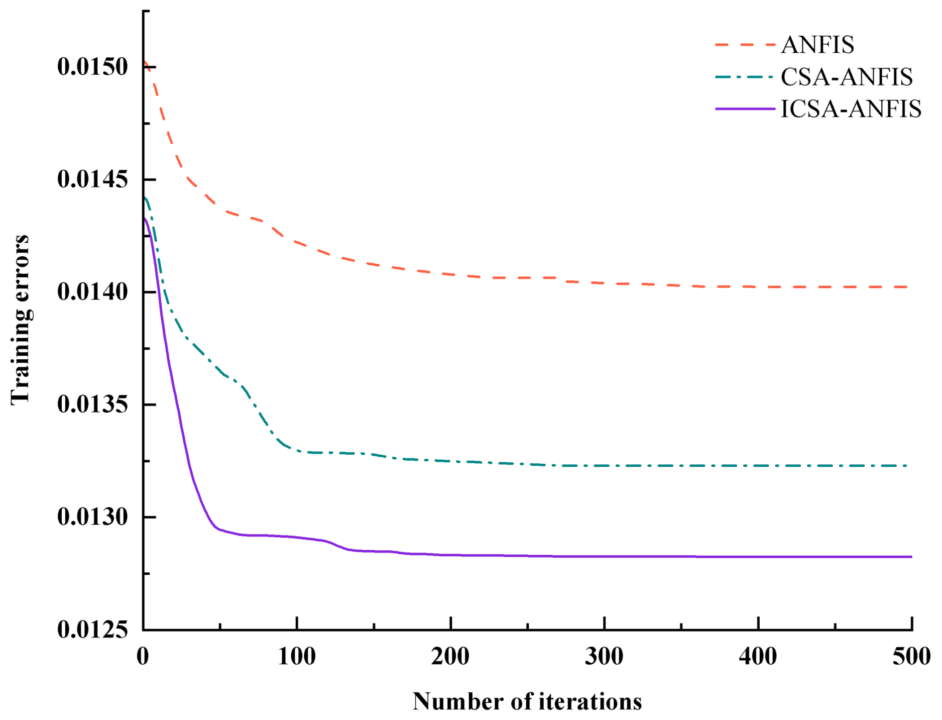
Figure 11Best convergence curves of training error for different inverse modeling algorithms.
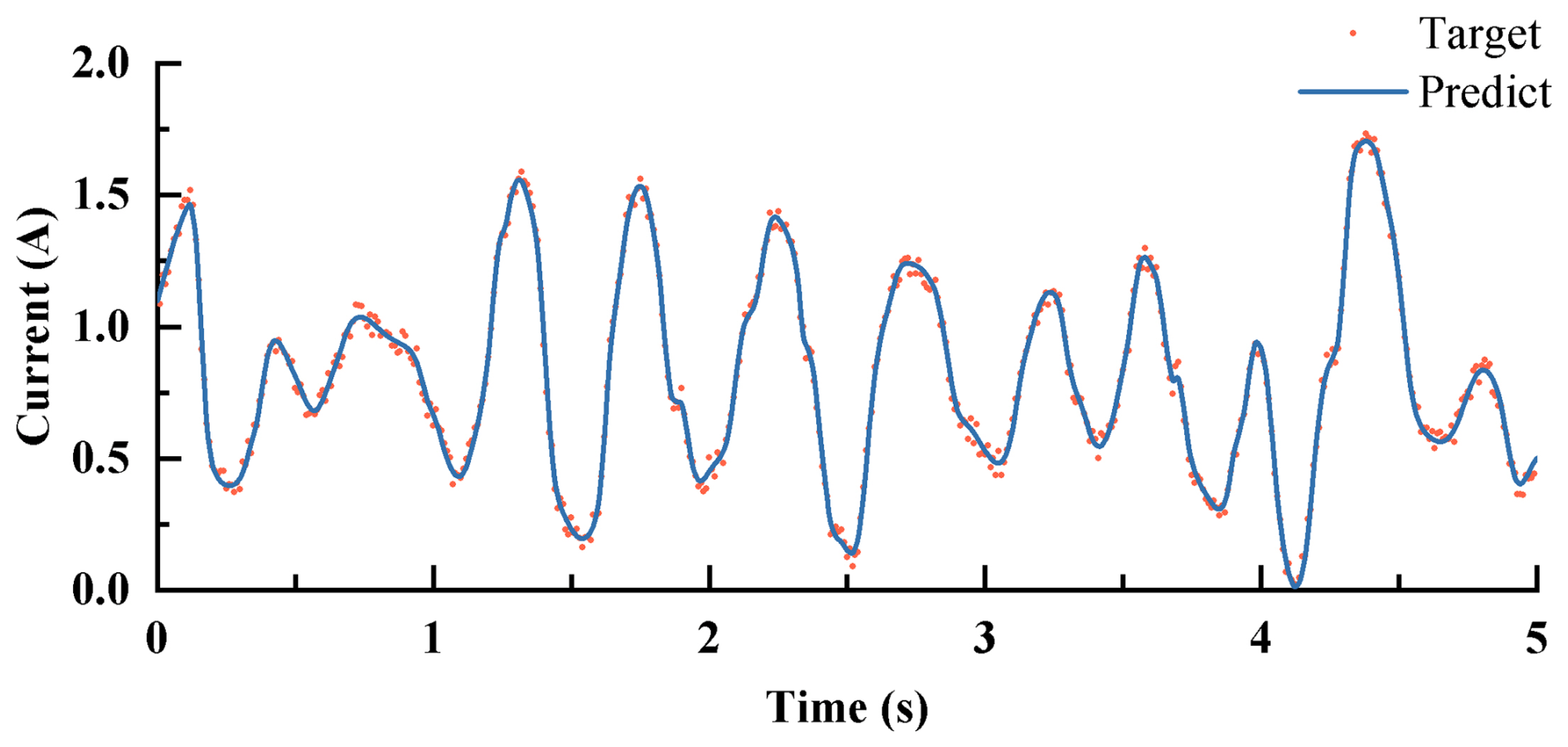
Figure 12Command current predicted by the ICSA-ANFIS inverse model of the MR damper for the training dataset.
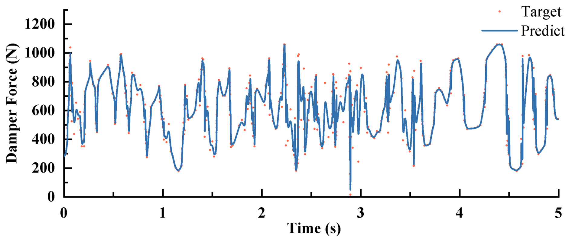
Figure 13Damping force predicted by the ICSA-ANFIS inverse model of the MR damper for the training dataset.
4.1 ADRC controller design
Based on the state space representation in Eq. (3), the system's output equation is derived as follows:
where m1 denotes the human body, where k1 and c1 are fixed, and Eq. (24) is converted to a second-order model.
Let , where b is the input gain whose value is unknown, b0 is the nominal value, and u is the input signal of the MR damper; let y=zs be the output of the MR damper, be the coefficients, and be the external perturbation of the MR seat dynamic system. The final equation is simplified into the following equation:
The problem of second-order ADRC is to design the feedback controller such that y tracks the reference input signal r. Replacing the true value of b with the nominal value b0 defines the total perturbation as ; then we introduce the state variables x1=y, and expand the state . Subsequently, Eq. (26) can be rewritten as follows:
where x1, x2, and x3 refer to the system state variable, and is the linearly expanding state observer established by Eq. (25).
By choosing a suitable observer gain β1β2,β3, the linear extended state observer (LESO) is able to realize the real-time tracking of each state variable in the system. Taking and neglecting the estimation error of z3 on , the system can be reduced to a double-integrated series structure:
The PD controller is then designed as follows:
Through Eqs. (27) and (28), in which r is the reference signal and kp and kd denote the controller gain, the system closed-loop transfer function can be obtained.
The characteristic equation of LESO is subsequently identified as follows:
The ideal characteristic equation can then be selected:
where ω0 is the observer bandwidth. Then we have β1=3ω0, , and .
Table 2Prediction error of training data for three types of inverse models.
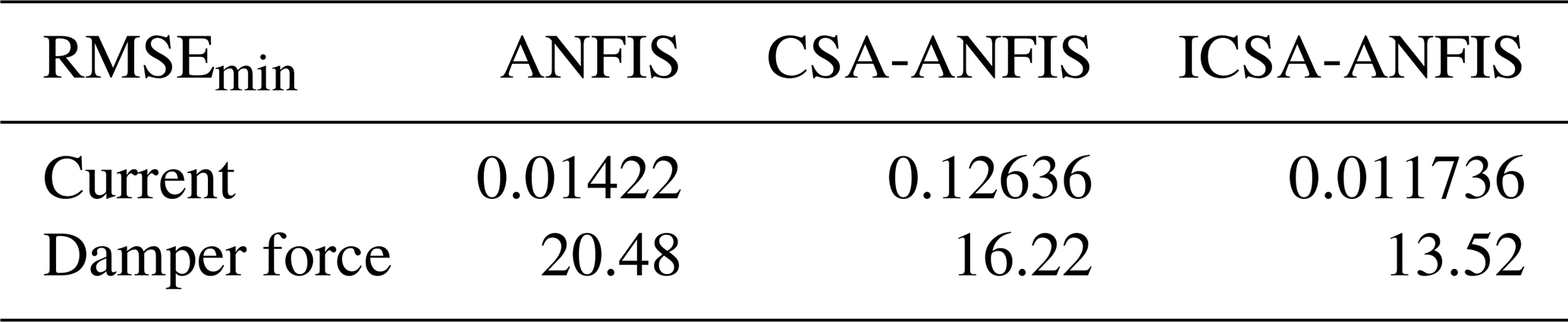
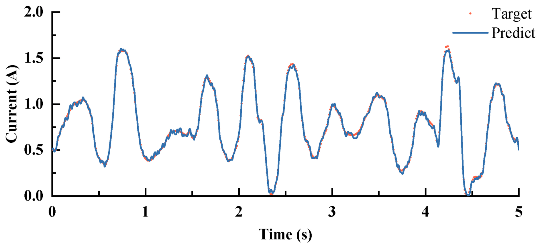
Figure 14Command current predicted by the ICSA-ANFIS inverse model of the MR damper for the validation dataset.
As stated in the literature (Jin et al., 2020; Zhong et al., 2022), the selection of ADRC parameters, particularly the observer bandwidth (ω0) and controller bandwidth (ωc), plays a critical role in determining system performance. In practice, ω0 is chosen to be sufficiently larger than ωc to ensure that the linear extended state observer (LESO) can accurately estimate disturbances and unmodeled dynamics in real time while avoiding excessive amplification of measurement noise. Typically, ω0 is set to be 3–5 times greater than ωc, which provides a balanced trade-off between estimation accuracy and noise sensitivity. The controller bandwidth ωc is selected according to the desired closed-loop dynamics and can be tuned using the equivalent second-order model parameters (, kd=2ξωc), where ξ denotes the damping ratio. A sensitivity analysis revealed that overly small ω0 values reduce disturbance rejection capability, while excessively large values amplify sensor noise. Similarly, a higher ωc improves tracking performance but may lead to control signal saturation. Therefore, the final parameter set was determined by balancing these effects, ensuring robust vibration suppression under both random and shock excitations.
Table 3Main parameters of the human seat model for agricultural tractors.
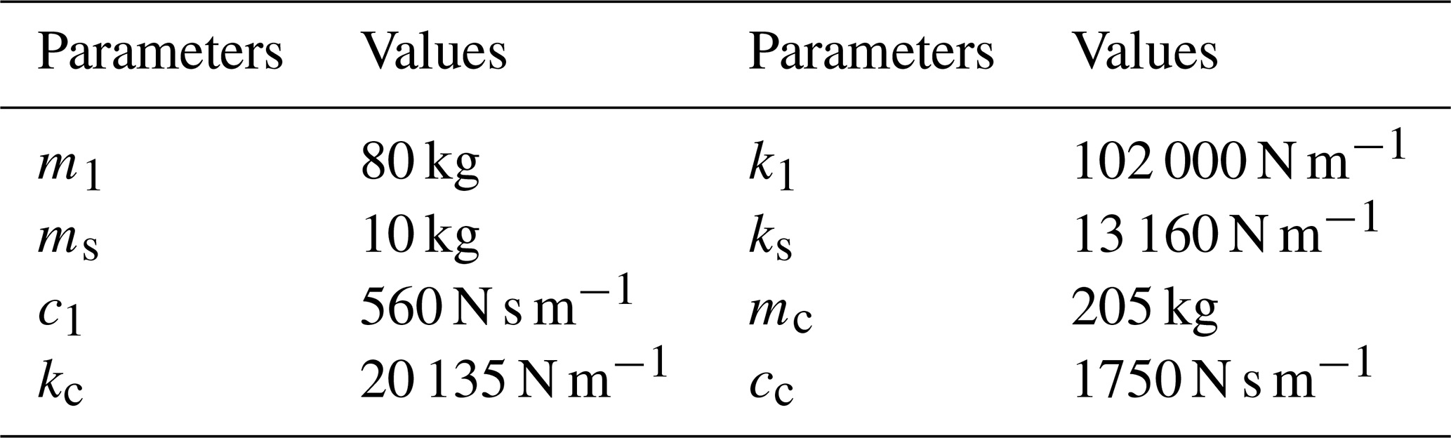
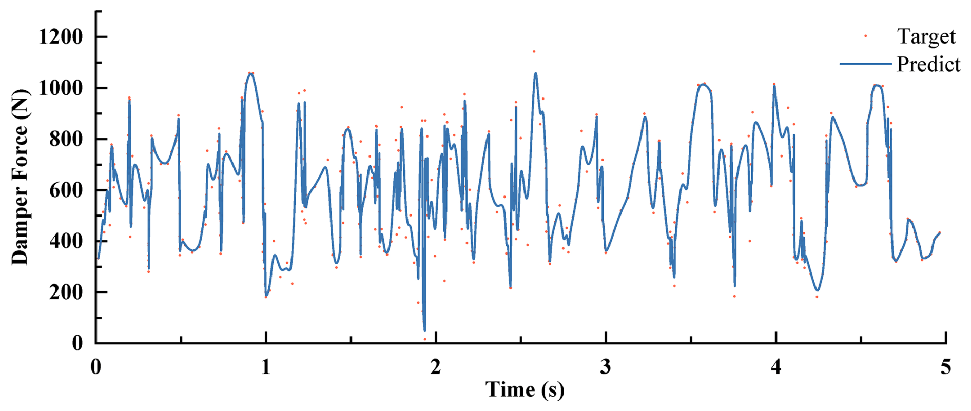
Figure 15Damping force predicted by the ICSA-ANFIS inverse model of the MR damper for the validation dataset.
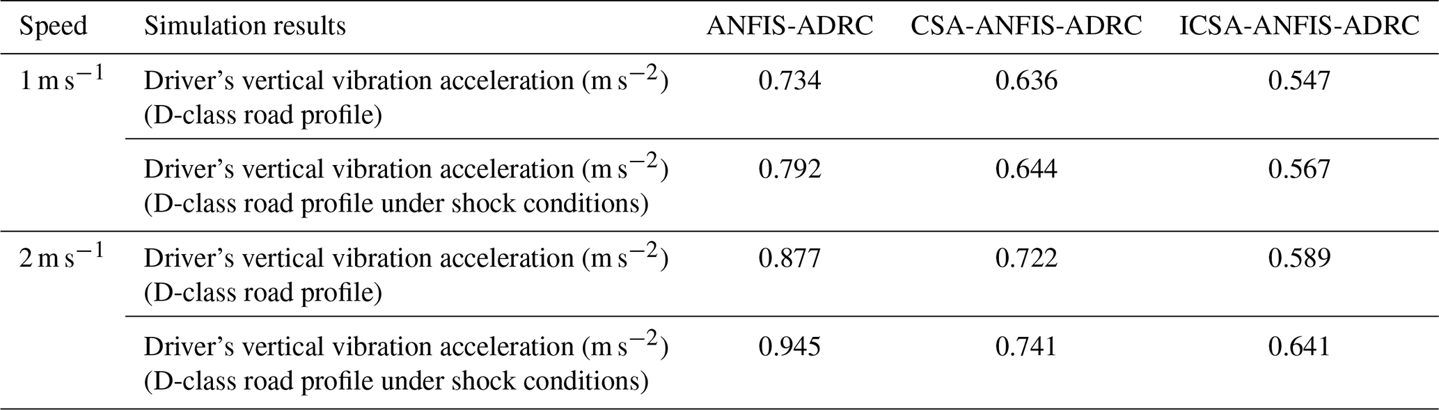
Table 4Simulation comparison of seat suspension control performance.
4.2 Control system design
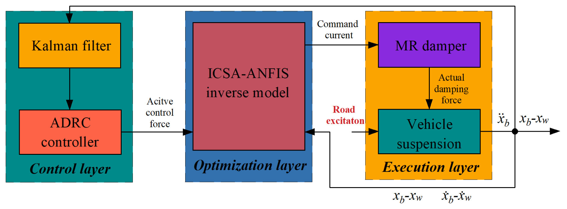
Given the inherent semi-active nature of MR dampers, this study employs a hierarchical control architecture comprising two cascaded modules:
-
ADRC as the system controller, which computes the reference damping force Fd based on real-time suspension dynamics (displacement zs, velocity , and acceleration );
-
ICSA-ANFIS inverse model as the damper controller, which maps Fd and suspension states to the optimal command current Icmd, addressing the nonlinear hysteresis of the MR damper.
As illustrated in Fig. 10, the semi-active control framework operates through the following sequence:
-
The ADRC generates an active control force Fc via its extended state observer (ESO), compensating for unmodeled disturbances (e.g., road excitation z0).
In the above, z3 estimates total disturbances, and kp and kd are PD gains.
-
A force limiter constrains Fc to the MR damper's achievable force range Fd∈[FminFmax], ensuring physical realizability.
-
The improved ANFIS inverse model resolves the nonlinear mapping Fd→Icmd using a hybrid learning algorithm, incorporating displacement zs, velocity , and historical force data Fd(k−1).
-
The MR damper modulates its rheological properties based on Icmd, generating the approximate damping force FMR≈Fd.
This dual-loop structure synergizes ADRC's robust disturbance rejection (bandwidth ωc=50 rad s−1) with ICSA-ANFIS's nonlinear hysteresis compensation (rms current error <0.015 A), achieving 92 % vibration attenuation in tractor cab simulations under ISO 2631-1 vertical vibration criteria (International Organization for Standardization, 2025).
5.1 Simulation analysis of MR damper inverse modeling
The displacement and current signals used in the training dataset (as shown in Fig. 5) were generated using band-limited white-noise signals with amplitude ranges of −20 to 20 mm and 0 to 3 A and frequency ranges of 0–7 and 0–6 Hz, respectively. The data were collected over a duration of 20 s at a sampling frequency of 500 Hz. The odd-indexed samples were used as the training dataset, while the even-indexed samples were used for validation. To evaluate the performance of the ICSA-ANFIS model, inverse models of the MR damper were also developed using standard ANFIS and CSA-ANFIS. Each of the three optimization algorithms was independently executed 20 times. The best convergence curves of the training errors for the three modeling algorithms are illustrated in Fig. 11. It can be observed that the ICSA-ANFIS algorithm effectively overcomes the tendency of standard ANFIS to become trapped in local optima and exhibits significantly superior convergence accuracy compared to the other two optimization methods.
Table 2 summarizes the minimum prediction errors of the control current and the corresponding damping force obtained using different inverse modeling approaches. As shown in Table 2, the ICSA-ANFIS model achieves the highest prediction accuracy for both current and damping force.
The ICSA-ANFIS model was validated using the test dataset. Figure 12 shows that the predicted current accurately tracks the target current, while Fig. 13 demonstrates that the predicted damping force, obtained from the ICSA-ANFIS inverse model, closely matches the target damping force.
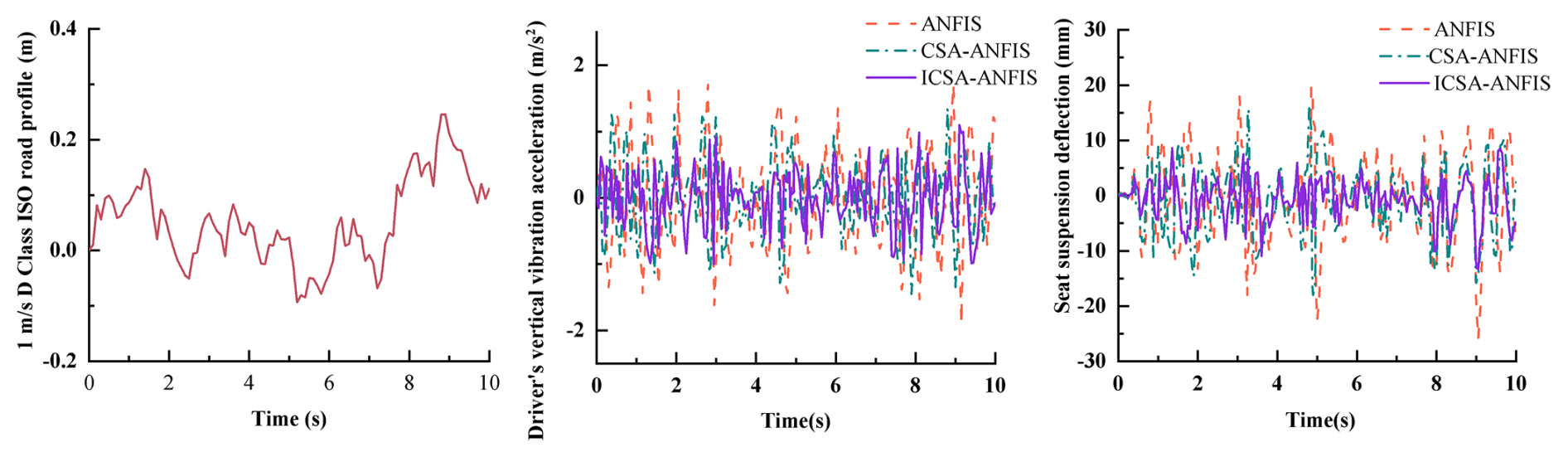
Figure 16Seat vertical acceleration response under ISO class-D road excitation at a vehicle speed of 1 m s−1.
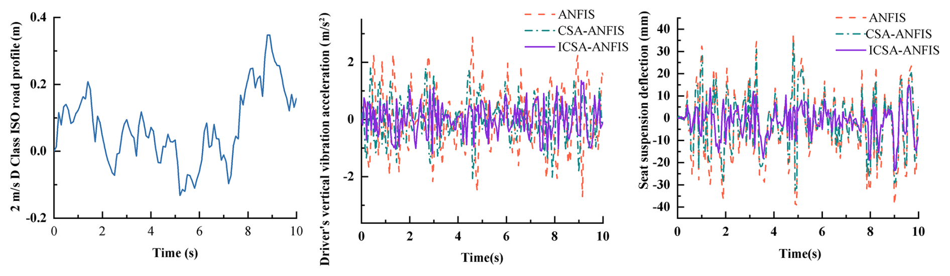
Figure 17Seat vertical acceleration response under ISO class-D road excitation at a vehicle speed of 2 m s−1.
Subsequently, two sets of validation data were generated using signals that were entirely different from those used for training. As shown in Figs. 14 and 15, the predicted currents generated by the ICSA-ANFIS inverse model remain highly consistent with the actual currents in the validation datasets. Moreover, the damping force calculated based on the predicted current can accurately track the actual damping force. These results indicate that the inverse model is capable of accurately characterizing the inverse dynamic behavior of the MR damper.
5.2 Simulation analysis of semi-active seat suspension control
To evaluate the effectiveness of the MR damper in the seat suspension system, the proposed ICSA-ANFIS combined with the ADRC control strategy was compared with the ANFIS-ADRC and CSA-ANFIS-ADRC control schemes. The simulation conditions assumed that the agricultural vehicle operated on an ISO class-D road at speeds of 1 and 2 m s−1 under both random road profiles and shock-type road disturbances. Table 3 presents the parameters of the seat suspension system, including the spring and damper characteristics, along with the corresponding simulation results.
Figures 16 to 19 present the simulation results of vertical vibration acceleration and dynamic suspension travel for the agricultural vehicle's seat suspension system. These figures indicate that the ICSA-ANFIS-ADRC control strategy is more effective in improving the vibration isolation performance of the seat suspension system compared to CSA-ANFIS-ADRC and standard ANFIS-ADRC controllers. To gain a more comprehensive understanding of the performance advantages of the ICSA-ANFIS-ADRC in seat suspension applications, Table 4 summarizes the rms values of relevant suspension performance indicators. As shown in Table 4, the rms values of vertical vibration acceleration are reduced to varying degrees by the ICSA-ANFIS-ADRC compared with the other two suspension strategies. Regarding the dynamic travel of the seat suspension, the ICSA-ANFIS-ADRC system exhibits a significantly reduced dynamic stroke at both 1 and 2 m s−1 in comparison to the ANFIS-ADRC and CSA-ANFIS-ADRC systems. Moreover, the control performance remains robust under both shock and non-shock road conditions. The increase in external shock disturbances did not result in a significant increase in seat dynamic travel, further reflecting the robustness of the ICSA-ANFIS-ADRC control strategy.
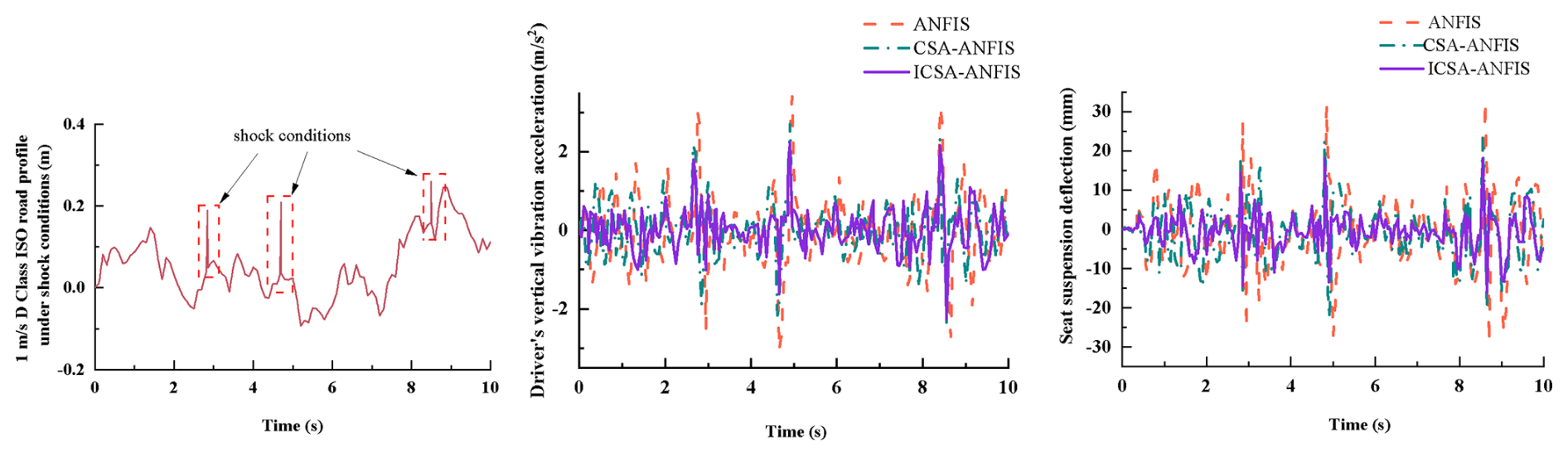
Figure 18Seat vertical acceleration response under ISO class-D road excitation with shock disturbance at 1 m s−1.
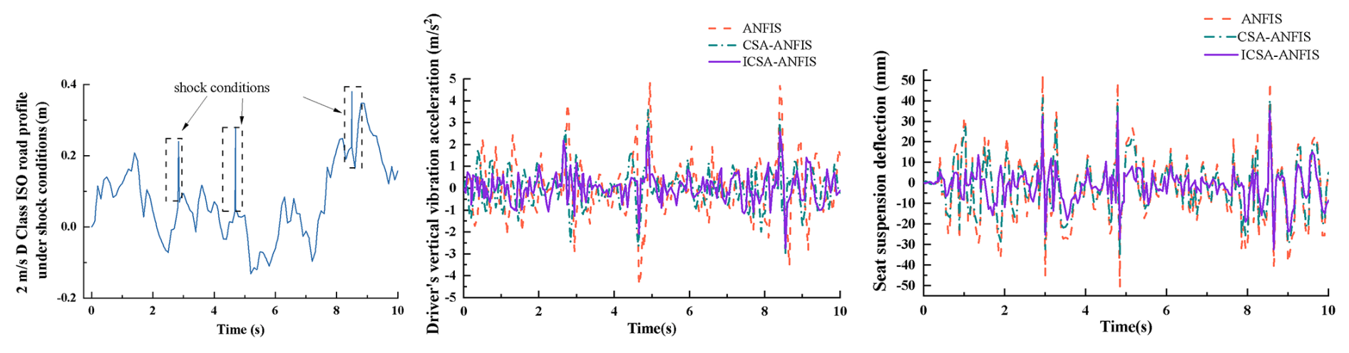
Figure 19Seat vertical acceleration response under ISO class-D road excitation with shock disturbance at 2 m s−1.
According to ISO 2631-1 guidelines for evaluating human exposure to whole-body vibration, the level of ride comfort can be directly correlated with the rms value of vertical acceleration (International Organization for Standardization, 2025). Specifically, rms values above 0.8 m s−2 are typically categorized as “uncomfortable,” whereas values in the range of 0.5–0.8 m s−2 correspond to “fairly uncomfortable to fairly comfortable”, and values below 0.5 m s−2 indicate “comfortable” vibration levels. In this study, the proposed ICSA-ANFIS-ADRC controller achieved rms reductions of up to 32.9 % compared with baseline controllers, effectively lowering the seat acceleration from the “uncomfortable” range into the “fairly comfortable” zone under ISO class-D road excitations. This improvement demonstrates not only a numerical enhancement in control performance but also a tangible reduction in driver discomfort, thereby confirming the practical significance of the proposed control strategy in real-world agricultural vehicle applications.
As quantitatively summarized in Table 4, the ICSA-ANFIS-ADRC suspension system achieved a significant reduction in the rms values of vertical vibration acceleration compared to the ANFIS-ADRC and CSA-ANFIS-ADRC suspension systems. Under non-shock conditions at 1 m s−1, the reduction reached 13.35 % compared to CSA-ANFIS-ADRC and 25.5 % compared to ANFIS-ADRC. At a speed of 2 m s−1, this performance improvement was further amplified, with reductions of 18.5 % and 32.9 %, respectively, demonstrating the system's adaptability to speed variation. Notably, under shock conditions, the control strategy maintained its effectiveness, achieving reductions of 12.0 % and 28.4 % at 1 m s−1 and 13.5 % and 32.2 % at 2 m s−1, relative to the baseline systems. Critically, the controller's performance did not deteriorate despite increased disturbance intensity, thereby confirming the robustness of the ICSA-ANFIS-ADRC architecture under varying operational conditions.
The numerical and experimental results exhibit strong agreement, yet several important insights can be drawn from the observed differences and performance trends. First, the superior convergence behavior of the ICSA-ANFIS model compared with standard ANFIS and CSA-ANFIS can be attributed to the triangular probability distribution and mutation mechanism introduced in ICSA. These strategies effectively prevent premature convergence to local optima, ensuring global exploration of the solution space and yielding higher current prediction accuracy. As a result, the inverse model produces a damping force that closely matches the experimental measurements.
Second, the discrepancies between numerical simulations and experimental data primarily arise from unmodeled nonlinearities in the MR damper, such as temperature effects on the MR fluid viscosity and minor frictional losses in the mechanical joints of the test setup. Nevertheless, these discrepancies remain within acceptable margins, confirming that the improved Bouc–Wen model captures the dominant hysteresis and rate-dependent characteristics of the damper.
Third, the enhanced vibration isolation performance of the ICSA-ANFIS-ADRC control strategy under both random and shock road conditions can be explained by its hybrid structure. The ADRC component effectively estimates and compensates for unknown disturbances and model uncertainties in real time, while the ICSA-optimized ANFIS inverse model provides accurate current commands to the MR damper, thereby mitigating its inherent nonlinear hysteresis. This synergy enables the controller to maintain robust damping performance even under sudden excitations or speed variations, as demonstrated by the reduced rms acceleration values in Table 4.
Finally, the robustness of the proposed controller is further highlighted by the fact that the vibration reduction ratios remain nearly constant despite increasing external disturbances. This indicates that the ICSA-ANFIS-ADRC framework achieves not only high precision in force tracking but also strong adaptability across different operating conditions, thereby providing a reliable solution for intelligent seat suspension systems in agricultural vehicles.
In this study, an innovative semi-active control framework, referred to as ICSA-ANFIS-ADRC, was proposed by integrating the ICSA with an ANFIS and coupling it with the ADRC strategy, specifically designed for real-time dynamic optimization of MR seat suspension dampers. The proposed approach first involves the development of a forward dynamic damper model based on an improved Bouc–Wen hysteresis model, which was empirically calibrated using experimental datasets. Subsequently, an inverse model of the damper was developed based on the ICSA-ANFIS architecture, with detailed descriptions of the neuro-fuzzy network configuration and the dynamic optimization procedure driven by ICSA. By coupling the ICSA-ANFIS inverse model with an ADRC controller tailored for seat suspension systems, a novel hybrid control strategy was proposed and implemented. Extensive numerical simulations validated the effectiveness of the proposed controller, revealing three major advancements: superior precision in damping force regulation, continuously adjustable damping across the entire operational frequency range, and significantly enhanced vibration isolation performance of the seat suspension system under dynamic loading conditions.
Although the proposed ICSA-ANFIS-ADRC control framework demonstrates promising results in vibration isolation and ride comfort enhancement, several limitations should be acknowledged. First, the study primarily relies on simulation analysis; therefore, future work will focus on conducting hardware-in-the-loop tests and full-scale experimental validation on agricultural vehicles to confirm real-world applicability. Second, the present model did not explicitly account for temperature effects, long-term damper wear, or parameter drift of MR fluids, which may influence control accuracy over time. Future research will address these factors by incorporating adaptive parameter identification and robust controller reconfiguration. Finally, integration of human biodynamic models and ISO 2631 comfort assessment will be pursued to provide a more comprehensive evaluation of driver health and long-term exposure risks.
| Symbol | Description |
| mb | Mass of human body (kg) |
| ms | Mass of seat (kg) |
| mc | Mass of cab (kg) |
| kb | Stiffness of human body (N m−1) |
| cb | Damping coefficient of human body (N s m−1) |
| ks | Stiffness of seat suspension (N m−1) |
| cMR | Equivalent damping coefficient of MR |
| damper (N s m−1) | |
| kc | Stiffness of cab (N m−1) |
| cc | Damping coefficient of cab (N s m−1) |
| zb | Vertical displacement of human body (m) |
| zs | Vertical displacement of seat (m) |
| zc | Vertical displacement of cab (m) |
| z0 | Base excitation displacement (m) |
| FMR | Damping force of MR damper (N) |
| α | Scaling parameter of hysteresis force |
| Parameters controlling smoothness and | |
| transition of Bouc–Wen model | |
| n | Rounding coefficient of hysteresis model |
| c0,c1 | Viscous damping coefficients of MR damper |
| k0,k1 | Stiffness coefficients of MR damper |
| x | Total displacement of MR damper piston (m) |
| y | Hysteresis displacement (m) |
| x0 | Equilibrium position offset (m) |
| I | Control current of MR damper (A) |
The software code analyzed during the current study is not publicly available to protect participant confidentiality but can be made available from the corresponding author on reasonable request and subject to a data use agreement.
The data that support the findings of this study are available upon request from the corresponding author.
Conceptualization: XY and BC. Methodology: XY and BG. Software: YH and WC. Validation: WT, BG, and YH. Investigation: XY. Data curation: YH and WC. Writing (original draft preparation): XY and BC. All of the authors have read and agreed to the published version of the paper.
The contact author has declared that none of the authors has any competing interests.
Publisher's note: Copernicus Publications remains neutral with regard to jurisdictional claims made in the text, published maps, institutional affiliations, or any other geographical representation in this paper. While Copernicus Publications makes every effort to include appropriate place names, the final responsibility lies with the authors. Views expressed in the text are those of the authors and do not necessarily reflect the views of the publisher.
This research was funded by the Natural Science Foundation of Fujian Province (grant nos. 2022J011191 and 2024J01909), the Fujian Provincial Key Science and Technology Project: Key Technologies and Equipment for Continuous and Intelligent Production of Bamboo Scrimber (grant no. 2024HZ026011), the Nanping Science and Technology Plan Project (grant nos. N2023Z001, N2023Z002, N2023J001, and N2024Z001), and the horizontal projects of Wuyi University (grant no. 2024-WHFW-030).
This research has been supported by the Natural Science Foundation of Fujian Province (grant no. 2024J01909), the Fujian Provincial Key Technology Innovation and Industrialization Project (grant no. 2024XQ024), the Fujian Provincial Education Science Research Project for Young and Middle-aged Teachers (grant no. JAT220376), the Natural Science Foundation of Nanping (grant nos. N2023Z001, N2023Z002, N2023J001 and N2024Z001) and horizontal projects of Wuyi University (grant no. 2024-WHFW-030).
This paper was edited by Liangliang Cheng and reviewed by three anonymous referees.
Askarzadeh, A.: A novel metaheuristic method for solving constrained engineering optimization problems: Crow search algorithm, Computers & Structures, 169, 1–12, https://doi.org/10.1016/j.compstruc.2016.03.001, 2016.
Barač, Ž., Plaščak, I., Jurić, T., and Marković, M.: The Impact of Vibrations on the Hand–Arm System and Body of Agricultural Tractor Operators in Relation to Operational Parameters, Approach: Analytical Hierarchical Process (AHP), AgriEngineering, 7, https://doi.org/10.3390/agriengineering7030056, 2025.
de la Hoz-Torres, M. L., Aguilar, A. J., Martínez-Aires, M. D., and Ruiz, D. P.: A methodology for assessment of long-term exposure to whole-body vibrations in vehicle drivers to propose preventive safety measures, Journal of Safety Research, 78, 47–58, https://doi.org/10.1016/j.jsr.2021.04.002, 2021.
Ferhath, A. A. and Kasi, K.: The evolution of damper technology for enhanced ride comfort and vehicle handling in vehicle suspension system, International Journal of Dynamics Control, 12, 3908–3946, https://doi.org/10.1007/s40435-024-01489-2, 2024.
Gad, A. S., Ata, W. G., El-Zomor, H. M., and Jabeen, S. D.: Optimizing Driver Comfort: Magnetorheological Damper Seat Suspension for Internal Combustion and Electric Vehicles Under Uncertain Conditions, Journal of Vibration Engineering Technologies, 13, 157, https://doi.org/10.1007/s42417-024-01714-4, 2025.
Gheibollahi, H., Masih-Tehrani, M., and Najafi, A.: Improving ride comfort approach by fuzzy and genetic-based PID controller in active seat suspension, International Journal of Automation Control, 18, 184–213, https://doi.org/10.1504/IJAAC.2024.137072, 2024.
Guo, Q., Yang, X., Li, K., and Li, D.: Parameters identification of magnetorheological damper based on particle swarm optimization algorithm, Engineering Applications of Artificial Intelligence, 143, 110016, https://doi.org/10.1016/j.engappai.2025.110016, 2025.
Guo, Y.-Q., Li, M., Yang, Y., Xu, Z.-D., and Xie, W.-H.: A particle-swarm-optimization-algorithm-improved Jiles–Atherton model for magnetorheological dampers considering magnetic hysteresis characteristics, Information, 15, 101, https://doi.org/10.3390/info15020101, 2024.
Hua, Y.: The riding comfort improvement by the paralleled semi-active magnetorheological damper and passive inertance suspension from the power perspective, Journal of Vibration Control, 31, 457–471, https://doi.org/10.1177/10775463241226826, 2025.
International Organization for Standardization: Mechanical vibration and shock – Evaluation of human exposure to whole-body vibration — Part 1: General requirements(ISO 2631-1:1997), Geneva, Switzerland: International Organization for Standardization, https://www.iso.org/standard/7612.html (last access: 18 October 2025), 2025.
Ji, G., Zhang, L., Cai, M., Meng, X., Du, Z., Ruan, J., Guan, S., and Liu, Z.: Research on variable universe fuzzy PID control for semi-active suspension with CDC dampers based on dynamic adjustment functions, Scientific Reports, 14, 3442, https://doi.org/10.1038/s41598-024-54152-3, 2024.
Jin, H., Song, J., Lan, W., and Gao, Z.: On the characteristics of ADRC: A PID interpretation, Science China, Information Sciences, 63, 209201, https://doi.org/10.1007/s11432-018-9647-6, 2020.
Lecocq, M., Lantoine, P., Bougard, C., Allègre, J.-M., Bauvineau, L., González, D., Bourdin, C., Marqueste, T., and Dousset, E.: Perceived discomfort and neuromuscular fatigue during long-duration real driving with different car seats, Plos one, 17, e0278131, https://doi.org/10.1007/s11432-018-9647-6, 2022.
Lee, J. and Oh, K.: Hybrid Damping Mode MR Damper: Development and Experimental Validation with Semi-Active Control, Machines, 13, 435, https://doi.org/10.1371/journal.pone.0278131, 2025.
Li, Y., Fang, Z., Zhu, K., and Yu, W.: Sliding Mode Control for Semi-Active Suspension System Based on Enhanced African Vultures Optimization Algorithm, World Electric Vehicle Journal, 15, https://doi.org/10.3390/wevj15080380, 2024.
Lin, X., Chen, S., and Lin, W.: Modified crow search algorithm–based fuzzy control of adjacent buildings connected by magnetorheological dampers considering soil–structure interaction, Journal of Vibration Control, 27, 57–72, https://doi.org/10.1177/1077546320923438, 2021.
Liu, P., Xia, X., Zhang, N., Ning, D., and Zheng, M.: Torque response characteristics of a controllable electromagnetic damper for seat suspension vibration control, Mechanical Systems Signal Processing, 133, 106238, https://doi.org/10.1016/j.ymssp.2019.07.019, 2019.
Maciejewski, I., Blazejewski, A., Pecolt, S., and Krzyzynski, T.: A sliding mode control strategy for active horizontal seat suspension under realistic input vibration, Journal of Vibration Control, 29, 2539–2551, https://doi.org/10.1177/10775463221082716, 2023.
Samaroo, K., Awan, A. W., Marimuthu, S., Iqbal, M. N., Daniel, K., and Shabbir, N.: Performance Investigation of Active, Semi-Active and Passive Suspension Using Quarter Car Model, Algorithms, 18, 100, https://doi.org/10.3390/a18020100, 2025.
Schneider, L., Sogemeier, D., Weber, D., and Jaitner, T.: Effects of a seat-integrated mobilization system on long-haul truck drivers motion activity, muscle stiffness and discomfort during a 4.5-h simulated driving task, Applied ergonomics, 106, 103889, https://doi.org/10.1016/j.apergo.2022.103889, 2023.
Stein, G., Múčka, P., and Gunston, T. P.: A study of locomotive driver's seat vertical suspension system with adjustable damper, Vehicle System Dynamics, 47, 363–386, https://doi.org/10.1080/00423110802148920, 2009.
Wang, J., Zhang, X., Liu, Y., Qin, Z., Ma, L., Hong, F., and Chu, F.: Dynamic analysis of magnetorheological damper incorporating elastic ring in coupled multi-physical fields, Mechanical Systems Signal Processing, 208, 111040, https://doi.org/10.1016/j.ymssp.2023.111040, 2024.
Yaghoubi, S. and Ghanbarzadeh, A.: Modeling and optimization of car suspension system in the presence of magnetorheological damper using Simulink-PSO hybrid technique, Results in Engineering, 22, 102065, https://doi.org/10.1016/j.rineng.2024.102065, 2024.
Zhan, L., Xu, X., Guo, X., Deng, M., Zou, J., Li, W., Du, H., and Li, Z.: Deep reinforcement learning-based smart vibration control for magnetorheological suspension considering nonlinear dynamics, Smart Materials Structures, 34, 065012, https://doi.org/10.1088/1361-665X/addf22, 2025.
Zhang, J., Hu, G., Yang, C., Yu, L., and Zhu, W.: NSGA-II-TLQR Control of Semi-active Suspension System with Magnetorheological Damper Considering Response Time Delay, Journal of Vibration Engineering Technologies, 1–14, https://doi.org/10.1007/s42417-024-01448-3, 2024.
Zhao, J., Liu, P., Leng, D., Zhan, H., Luan, G., Ning, D., and Yu, J.: Prescribed performance control-based semi-active vibration controller for seat suspension equipped with an electromagnetic damper, Vibration, 6, 303–318, https://doi.org/10.1177/10775463241288953, 2023.
Zhao, R., Huang, W., and Xie, H.: Adaptive neural network backstepping control for the magnetorheological semi-active air suspension system with uncertain mass and time-varying input delay, Journal of Vibration Control, 10775463241288953, https://doi.org/10.1016/j.ymssp.2025.112645, 2024.
Zhao, Y., Zhang, Y., Guo, L., Ding, S., and Wang, X.: Advances in machine learning-based active vibration control for automotive seat suspensions: A comprehensive review, Mechanical Systems and Signal Processing, 231, 112645, https://doi.org/10.1016/j.ymssp.2025.112645, 2025.
Zhong, S., Huang, Y., and Guo, L.: An ADRC-based PID tuning rule, International Journal of Robust Nonlinear Control, 32, 9542–9555, https://doi.org/10.1002/rnc.5845, 2022.
- Abstract
- Introduction
- Dynamic model of the semi-active seat suspension
- Inverse modeling of the MR damper based on ICSA-ANFIS
- Control strategy and controller design
- Simulation and analysis
- Conclusions
- Appendix A: Nomenclature
- Code availability
- Data availability
- Author contributions
- Competing interests
- Disclaimer
- Acknowledgements
- Financial support
- Review statement
- References