the Creative Commons Attribution 4.0 License.
the Creative Commons Attribution 4.0 License.
 | 24 Jan 2025
Design and validation of a programmable dual-tunnel soft pneumatic origami actuator with a large maximum shrinkage rate for reciprocating motion
Rongna Xu
Qiaolian Xie
Yuxin Zheng
Cuizhi Fei
Vincenzo Parenti Castelli
Hongliu Yu
Soft actuators have attracted significant research in various domains owing to their flexible motion characteristics. However, the applications of soft actuators are constrained by their low force-to-weight ratio and maximum shrinkage rate, which is the ratio of the maximum stroke to the extreme length of the actuator, considerably augmenting the driving energy and occupied area. This paper presents a novel dual-tunnel soft pneumatic origami actuator capable of providing a large maximum shrinkage rate for reciprocating motion. The inner tunnel is constructed by the origami mechanism chamber, and the outer tunnel is formed by the origami mechanism in conjunction with the outer soft skin. A programmable design method for the proposed actuator is presented, based on its geometric parameter model and stiffness model. A kinematics model is developed to analyze the motion behavior and characteristics of the actuator's reciprocating motion. The prototype is fabricated using lightweight materials, such as oriented polypropylene and hard cardboard, on which tensile and load experiments are conducted. The results verify the motion characteristics of the soft actuator and the accuracy of the model. Compared to other linear actuators, the soft origami actuator is lightweight (weighing 5 g), has a large maximum shrinkage rate (61 %) and boasts a force-to-weight ratio of 600. The design demonstrates the extensive application potential of soft actuators with the origami mechanism.
- Article
(2162 KB) - Full-text XML
-
Supplement
(5012 KB) - BibTeX
- EndNote


Rehabilitation robots serve as the primary apparatuses for the rehabilitation of patients afflicted with limb dysfunction. Research on the characteristics analysis in rehabilitation training reveals that human–machine motion is nonlinear. Robots designated for rehabilitation purposes are obliged to exhibit a high level of flexibility (Xiloyannis et al., 2019). Most early rehabilitation robots were actuated by rigid mechanical structures. Soft rehabilitation robots are lighter in mass and more flexible compared to rigid rehabilitation robots. The flexible structure lessens the harm caused by the incoherent human–machine motion. As a consequence, research on soft robotics is currently concentrating on the issue of human–robot interaction (Lamine et al., 2017; Samper-Escudero et al., 2020). The performance parameters of soft actuators are crucial to exoskeleton robots, as the actuators are their main components.
The research on soft actuators has attracted significant global attention. Soft actuators, classified by driving type, include dielectric elastomer actuators (Jung et al., 2007; Shintake et al., 2016), magnetic responsive actuators (Diller et al., 2012; Floyd et al., 2011), thermal responsive actuators (Sun et al., 2023; Rodrigue et al., 2017), liquid crystal elastomers (Kularatne et al., 2017; Zhang et al., 2016, etc.), photo-responsive actuation (Weng et al., 2016; Hu et al., 2017; Kwan et al., 2018) and pressure-driven actuation (Yang et al., 2019; Liu et al., 2019; Erel et al., 2022). Pneumatic flexible actuators (PFAs) (Guan et al., 2020) have gained considerable popularity in the field of flexible actuators due to their characteristics of being lightweight and low cost and having outstanding compliance. PFAs are commonly used in the healthcare industry and other sectors. Wang et al. (2022) developed a muscle–tendon system mimicking a flexible actuator based on the investigation of a semimembranosus muscle mimicking a HimiSK actuator. The limitations of this mechanism are its lengthy schedule period and single driving direction. In the context of deformation vehicles, Feng et al. (2015) studied a soft actuator based on embedded pneumatic muscle fibers (PMFs), which enabled the adaptive wing camber to change. This approach offers rapid production times and utilizes low-cost commercial materials. However, it has a relatively low maximum elongation–shrinkage rate and occupies a relatively large area. To enhance the maximum elongation–shrinkage rate of the pneumatic actuators, the origami mechanism has been proposed to guide their motion along a predefined desired trajectory. The origami mechanism is a technique for constructing rigid structures from folded paper, which possesses the advantages of compactness, diverse shape variations and a large displacement ratio (Meloni et al., 2021). The origami mechanism is widely used in bionic robots (Pagano et al., 2017; Zhakypov and Paik, 2018), industrial grasping robots (Firouzeh and Paik, 2017), flying robots and aerospace mechanisms (Morgan et al., 2016), etc. Paez et al. (2016) utilized the origami mechanism as the shell of the pneumatic actuator, which protects the flexible air cavity and provides orientation for the actuators. Bending experiments were conducted to demonstrate that the origami mechanism shell has no impact on the bending angle of the pneumatic actuator. However, this mechanism is incapable of withstanding high load forces. Li et al. (2019) developed a rigid-flexible coupled piston structure based on the origami mechanism. Lee et al. (2021) applied the origami mechanism to the deformable wheel. The singularity of the motion of these actuators fails to meet the requirement for multiple degrees of freedom in single-joint devices, such as the shoulder and wrist joints of rehabilitation exoskeletons.
The aforementioned pneumatic actuators exhibit the following shortcomings:
-
The intricate manufacturing procedures lead to escalated costs.
-
The limitation of the maximum elongation–shrinkage rate necessitates a larger area to generate greater displacements.
-
The low force-to-weight ratio means that the actuator, despite its heavier weight, generates a relatively small load force, thus increasing the energy consumption of the equipment.
This paper proposes a novel soft pneumatic actuator with a higher force-to-weight ratio and a large maximum shrinkage rate, inspired by previous investigations. We have a geometric parameter model to simplify the design and fabrication of soft pneumatic actuators that incorporate the tunnel cavity origami mechanism. The origami mechanism, combined with a flexible skin, forms a dual-tunnel actuator, enabling the actuator to perform controlled reciprocating motion. The anisotropic stiffness characteristics of the actuator allow it to move in both linear and curved directions. This actuator is expected to find extensive applications in the fields of miniaturized robotics and high-load, large workspace equipment, particularly when more drives are connected in parallel or series.
The order of this paper is as follows: Sect. 2 introduces the primary design of the soft pneumatic actuator, including a model of geometric parameters and an analysis of the stiffness characteristics of the tunnel cavity origami mechanism. Additionally, a kinematic analysis of the actuator will be conducted. Section 3 presents a preliminary prototype of the origami actuator and discusses the experimental and simulation results. Finally, Sect. 4 draws the conclusions and outlines future prospects.
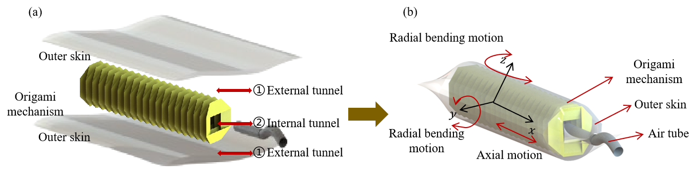
As illustrated in Fig. 1, the dual-tunnel soft pneumatic origami actuator is composed of an outer skin (oriented polypropylene), an origami mechanism (hard cardboard) and an air tube. The actuator features two tunnels: the inner tunnel is constructed by the origami mechanism chamber, and the outer tunnel is formed by the origami mechanism and the outer soft skin. The origami mechanism is enveloped by two pieces of outer skin. One end of the actuator is reserved for connection to the gas pipe, while the other three sides are heat-pressed together. Figure 1a shows the components of the soft pneumatic origami actuator. As demonstrated in Fig. 1b, the actuator is capable of motion in three dimensions: stretching, rotating and bending.
2.1 Geometric parameter model of the soft pneumatic origami actuator
The tubular cavity origami mechanism of the soft pneumatic actuator dictates the intended direction of movement. The actuator achieves linear movement through the differential pressure between the inner and outer cavities. In the initial state, the internal pressure is equal to the external air pressure. When the air pressure increases or decreases, it causes a change in the internal volume of the air bag. This alteration in the volume of the air bag actuates the origami mechanism, thereby inducing the deformation of the actuator.
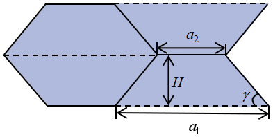
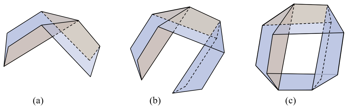
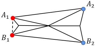
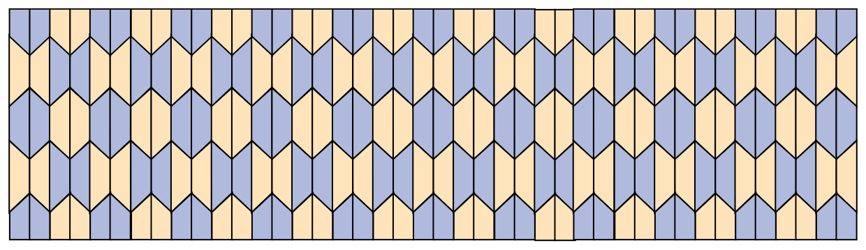
The origami mechanism can currently be categorized into three types: the Miura-ori pattern, the Yoshimura pattern and the diagonal pattern. The Yoshimura origami structure has larger scalability and volume of internal space, which facilitates the formation of a sealed space and can generate significant volume deformation when designed as a columnar structure. Therefore, the Yoshimura pattern has been chosen to design the tubular cavity origami mechanism. As viewed in Fig. 2, the single crease unit of the Yoshimura pattern consists of multiple equilateral trapezoids. The height of the trapezoid is H, the length of the lower bottom edge is a1, the upper bottom edge is a2 and the bottom angle is γ. The tubular cavity origami mechanism designed in this paper is the closed tubular structure. It is assumed that each of its cross-sections is a regular n-sided polygon (n does not include the number of the equilateral trapezoidal hypotenuse edges). It can be deduced from the folding characteristics of the Yoshimura origami mechanism that the paper undergoes a flip and a reverse fold as n increases, as shown in Fig. 3. In this regard, the closed tubular structure can only be formed when n is an even number, and it can not be formed when n = 2; thus, n ≥ 4. Figure 4 shows that the tubular cavity origami mechanism can achieve radial bending motion by changing the distance between point A1 and point B1 while performing axial motion. Therefore, n = 4 is selected as the number of sides for the tubular cavity origami mechanism. This realizes the multi-degree-of-freedom motion requirement of the actuator and avoids the complication of the fabrication process of the origami mechanism at the same time. The crease design of the origami mechanism is presented in Fig. 5.
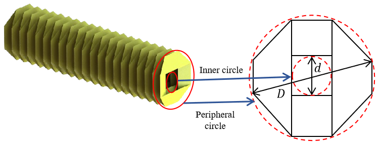
It is crucial to design the parameters of the origami mechanism in a reasonable manner so that the creases do not cause any deformation or bending during the process of folding the paper from a plane to the tubular structure. The inner and outer circles are set as the boundary conditions of the origami mechanism cross-section. Figure 6 shows the inner and outer circles of the tubular cavity origami mechanism cross-section, where D represents the diameter of the outer circle, and d represents the diameter of the inner circle. Through the analysis of the planar structure, the relationship between the parameters of the origami mechanism and the cross-section of the inner and outer circles as well as n can be determined:
2.2 Stiffness characterization of the tubular cavity origami mechanism
The stiffness characteristics of the tubular cavity origami mechanism are analyzed below to illustrate the actuator's orientation. The axial stiffness and the radial stiffness of the origami mechanism are calculated and analyzed as follows.
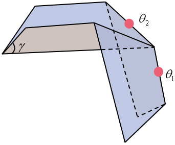
The origami mechanism consists of a number of trapezoidal surfaces, which are connected to each other by hill and valley creases. Figure 7 shows the intersection of hill and valley creases at a single point. There are interactions between the stiffness of neighboring creases, so the elastic potential energy generated at a single vertex has been calculated to determine the stiffness of the entire origami mechanism. Once the parameters of the trapezoidal surfaces of the origami mechanism are known, the morphology of the origami mechanism can be determined by representing the two dihedral angles that connect the vertices:
The axial length of the unit origami mechanism is Lr, and the radial length is Wr; these two parameters can be expressed as
The elastic potential energy of the origami mechanism can be obtained from the following equation:
where Tn is the number of the two dihedral angles, and ki is the stiffness of the two dihedral angles. The stiffness of the dihedral angle is calculated as follows.
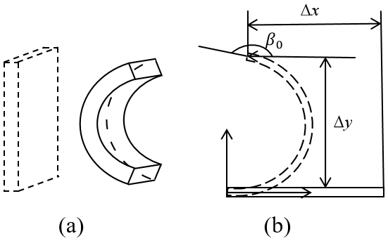
The crease has been folded as shown in Fig. 8, and the crease part produces a permanent arc deformation. As shown in Fig. 9, the arc stiffness can be calculated according to the Euler–Bernoulli beam theory, and the deformation can be obtained as
where ki,fol is the stiffness of the folding dihedral angle. According to the geometric relationship of the arc, the relationship between the longitudinal deformation of the arc and the bending angle can be obtained:
The relationship between the stiffness of the arc and the bending angle can be presented by
The crease of the origami mechanism made in this paper is formed by laser cutting. The cutting crease is the equal-length dashed line, and the cutting length of laser cutting is Llaser. The length of the single crease unit is b. As shown in Fig. 8b, the number of the crease fragments within a single crease unit is Nlaser,ke, which can be obtained as
Then the total length of the laser cut is obtained.
Assuming that the crease length is b, the stiffness of the crease after laser cutting is
Substituting it in the above equation for the stiffness of the initial crease, the relationship between crease stiffness and dihedral angle is
The length of the crease at the dihedral angle θ1 is a2; hence the stiffness of the crease at the dihedral angle θ1 is
The length of the crease of the dihedral angle θ2 is Hsin γ, and the crease stiffness of the dihedral angle θ2 is calculated as
Then, the elastic potential energy of the tubular cavity origami mechanism can be established as
Since the number of layers of the origami mechanism is N and the number of n is 4, there are a total of 4N dihedral angles and 4N dihedral corners. The axial force on the origami mechanism in equilibrium can be obtained from the following equation:
The axial stiffness of the origami oriented mechanism is
Similarly, the radial force of the tubular cavity origami mechanism in equilibrium can be obtained as
The radial stiffness of the tubular cavity origami mechanism is
The value of the stiffness can be obtained to substitute the design parameters' tubular cavity origami mechanism into Eqs. (16) and (18). The axial stiffness of the origami mechanism is 0.003 N mm−1, and the radial stiffness is 0.965 N mm−1. The results show that the axial stiffness is less than the radial stiffness. Consequently, when an external force is applied to the origami mechanism, the axial motion will remain unaffected by movements in other directions.
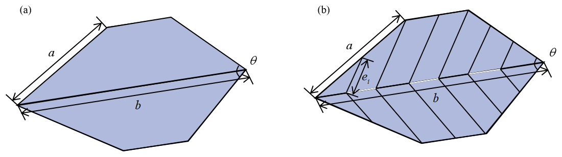
Figure 8The crease unit: (a) the crease unit before laser cutting and (b) the crease unit after laser cutting.
A numerical simulation of the origami mechanism's stiffness is conducted to determine the relationship between the mechanism's stiffness and the angle of a single crease.
In order to verify the accuracy of the above stiffness formulas, we calculate the relative errors between the ABAQUS and stiffness formulas. The simulation includes the stress and strain of the origami mechanism at θ = 15°, θ = 30°, θ = 45° and θ = 60°. The relative error between the simulated values of ABAQUS and the theoretical model is calculated to be 7 %.
The stiffness model proposed by Chen et al. (2023) has been calculated for the purpose of verifying the accuracy of the stiffness model presented in this paper. The result is provided as follows:
As shown in Fig. 10, the stiffness value of Chen et al. (2023) compared with this paper obviously has a large error with the ABAQUS simulation value, and its relative error is 17.09 %.
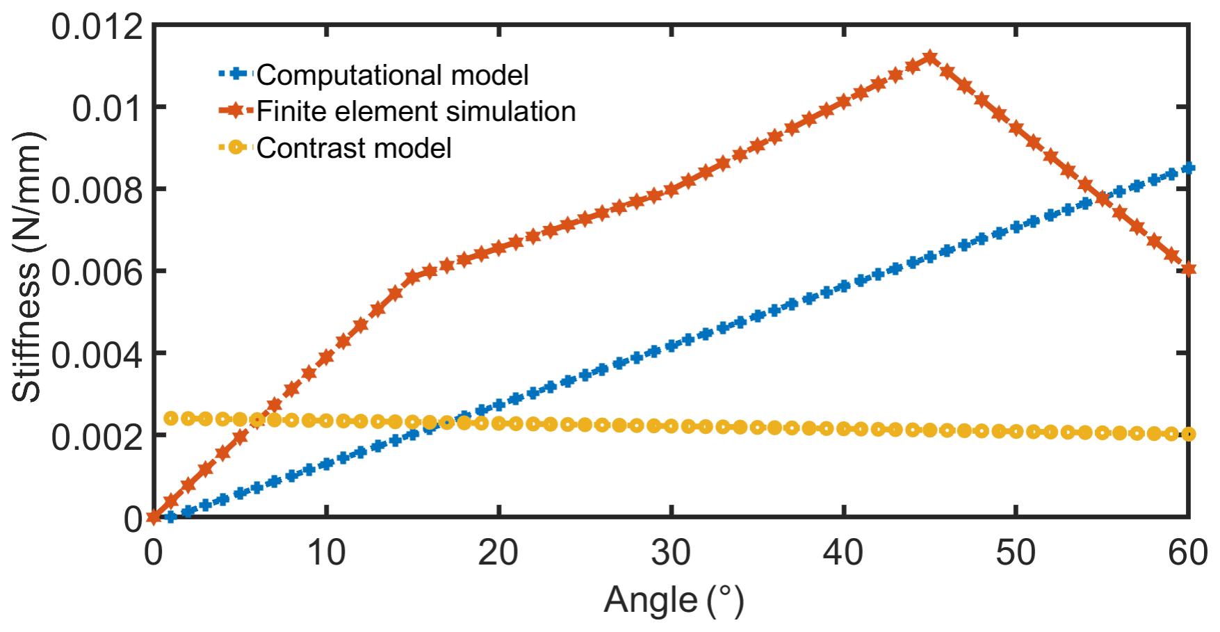
Figure 10Origami mechanism stiffness comparison of the computational model, the finite-element simulation and the contrast model.
2.3 Performance analysis of the inner- and outer-cavity drive
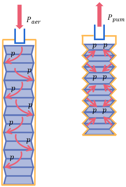
As shown in Fig. 11, the gas inside the soft pneumatic origami actuator is inflated/aspirated to achieve the expansion/contraction. In order to characterize the drive performance and improve the control accuracy, this paper establishes the relationship between the displacement and the internal air pressure of the soft pneumatic actuator during aeration and pumping, respectively. The material of the inner origami mechanism is hard cardboard, and the portions outside the crease do not undergo bending deformation. Therefore, the effect of material deformation on the displacement of the actuator has been ignored. The tubular cavity origami mechanism designed in this paper has a total of N layers, and the displacement of the origami mechanism can be obtained as
This paper simplifies the model of the tubular-cavity origami mechanism into a single fixed-stiffness spring model due to its complex mechanism. According to the potential energy balance theory, when the actuator receives negative pressure, the kinetic energy generated by the soft pneumatic actuator is equal to the sum of the elastic potential energy of the origami mechanism and the work done by the gas. Since the actuator consists of an inner cavity and an outer cavity, and the gas works on both, the potential energy equilibrium model can be derived:
where EK is the kinetic energy generated by the actuator; ES is the elastic potential energy of the origami mechanism; and WP,int and WP,out are the work done by the gas of the internal and external cavity, respectively. The displacement of the actuator is controlled by the gas pressure difference between the inner and outer cavities, so the two-way fluid–solid coupling model is established, and the internal gas pressure of the actuator is determined according to the ideal gas law:
where P0 and P are the internal air pressure of the actuator before and after the application of air pressure, respectively; P′ is the applied gas pressure; T0 and T are the internal temperature of the actuator before and after the application of air pressure, respectively; and T′ is the applied gas temperature. Assuming that the gas temperatures remain consistent, Eq. (23) can be simplified as
Then, the internal structure of the origami mechanism is discretized into trapezoidal units to calculate its internal volume. The single layer of the origami mechanism designed in this paper consists of eight trapezoidal units of the same volume, and the height of the single layer in the initial state is h0. Therefore, the volume of the actuator is
The pressure inside the actuator during the movement can be calculated as
The difference in air pressure between the inside and outside is obtained as
where Pout is the external pressure. It can be deduced that the work done by the air pressure applied to the actuator is
where h′ is the height of the single layer of origami as the pressure is P′, and . The elastic potential energy of the origami mechanism can be derived from the equation for the elastic potential energy of a spring. Since the air pressure is used almost exclusively for the stretching and elongation of the origami mechanism during the inflation process, the work done by the air pressure in the external cavity of the actuator is considered insignificant. Therefore, the displacement of the actuator during the extension process can be calculated using the kinetic energy formula of the actuator:
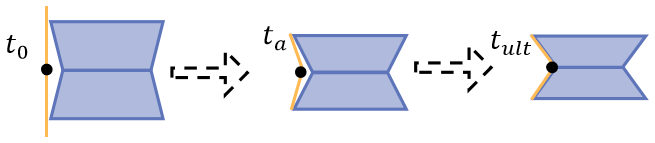
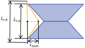
During the process of drive pumping, the pressure exerted by the outer cavity on the origami mechanism serves as the main driving force for contraction. The following section will calculate the work done within the outer cavity of the drive. The finite prime method (FPM) has been used to calculate the pressure on the origami mechanism during shrinkage of external oriented polypropylene. A finite number of mass points on the oriented polypropylene is defined. Figure 12 presents the motion trajectory of mass point. t0 is the initial moment, t0 is the pathway moment and tult is the termination moment. Since the origami mechanism is a symmetric arrangement and combination, the unilateral force of a single origami unit is investigated first.
According to Newton's second law of motion force and acceleration, the mass point can be always in dynamic equilibrium during motion. The force generated by the mass point can be obtained as follows:
where ma is the weight of the point, is the acceleration of the point and is the acceleration of the mass point. Explicit time integration is used to calculate the force of the mass point (Yu and Luo, 2009):
where Δt is the time unit step of the mass point, which can be obtained as
where tsum is the total time of particle motion, and na,sum is the total time of particles. Similarly, the time unit of particles satisfies the following relationship:
As shown in Fig. 13, xsum is the total length of particle motion, Lr,0 is the initial height of single layer origami and the height in ta is Lr,a. xsum can be obtained as follows:
The force of the mass point can be expressed as follows:
The kinetic energy of the total particles is given by the following equation:
Then, the drive model during contraction can be obtained:
3.1 Actuator prototype
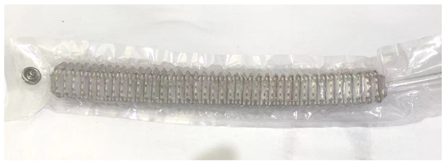
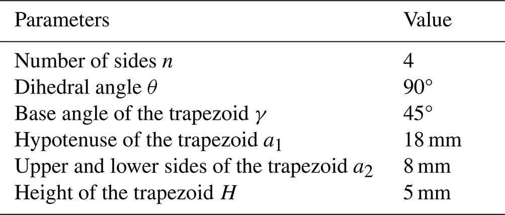
Figure 14 shows the experimental prototype of the soft pneumatic origami actuator (the manufacturing process of the actuator is elaborated in Movie S1 in the Supplement). The crease of the origami mechanism has been determined. The parameters associated with the crease can be obtained according to the relevant constraints, as shown in Table 1. The hard cardboard was selected for the origami mechanism on the request of the actuator, which has lower hardness and can be cut by a laser-cutting machine for crease cutting. A gas tube was inserted at the cross-section of the origami mechanism after the tubular cavity origami structure was formed by reverse folding, and the end of the gas tube was about 1 cm deep from the cross-section of the tubular cavity origami mechanism. The oriented polypropylene exhibits good fatigue resistance and flexibility. An external air cavity was formed after heat pressing with the oriented polypropylene, which serves to seal the origami skeleton and the tubes.
3.2 Tensile experiment and result analysis
An equal load tensile experiment has been conducted on the actuator to characterize its tensile properties and verify the accuracy of the theoretical displacement mentioned earlier. Figure 15 shows the experimental setup. The air pump applied different values of negative pressure to the actuator, while the load was kept consistent. The internal air pressure of the actuator was gradually decreased. The displacement of the actuator at each moment under different negative pressures was measured, and the results were analyzed. The relationship between the air pressure generated by the air pump and the voltage supplied by the power supply is linear. The principle of voltage regulation for the air pump is as follows: a PWM (pulse width modulation) speed control circuit board is used to adjust the voltage of the air pump, which regulates the airflow and has a linear relationship with the air pump's pressure. Therefore, the experiment adjusted the voltage of the air pump to control the airflow. Additionally, by controlling the inflation time of the air pump, it was ensured that the change in the air pressure inside the actuator occurred linearly.
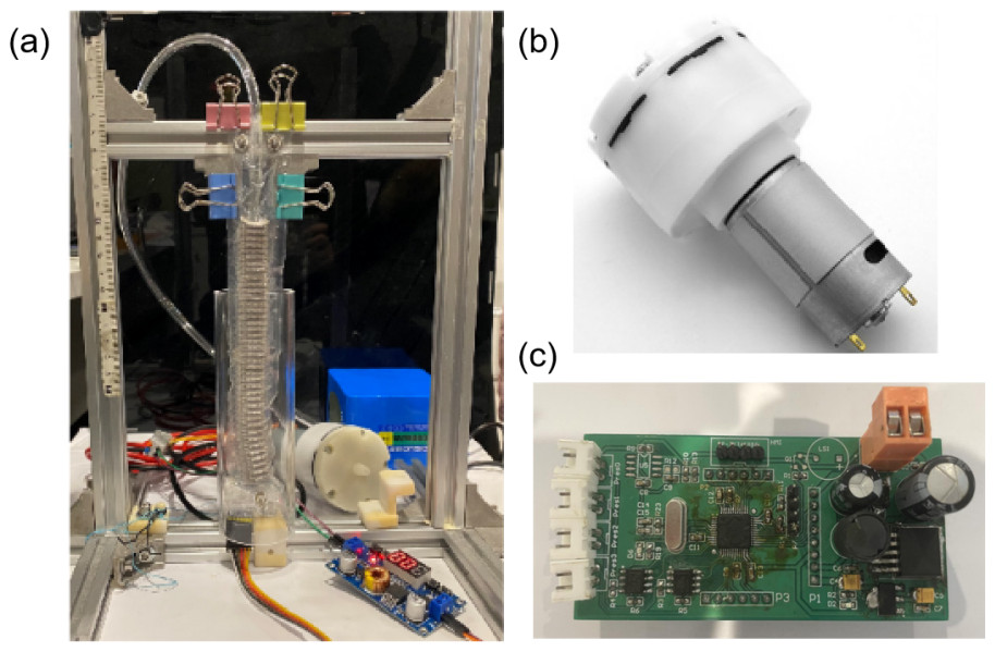
Figure 15Experimental device of the soft pneumatic actuator. (a) Experimental platform. (b) Experimental air pumps with a flow rate of 50 L min−1 and maximum negative pressure of −87 kPa. (c) PWM speed control circuit board.
As described in the above driving model for gas pressure control, the experiments in this paper have driven the actuator by changing the voltage of the air pump to facilitate the drive. The following section will establish the conversion relationship between gas pressure and voltage. According to the deformation, the gas pressure formula can be derived:
where R is a constant (the value is 8.314), T is the gas temperature, ρ is the gas density, t is the pressure supply time of the air pump, M is the average molar mass of the air (the value is 28.97 g mol−1), vap is the flow rate of the air pump and V is the internal volume of the actuator.
The relationship between the voltage and displacement of the actuator can be obtained by bringing Eq. (39) into Eq. (37).
The experimental instruments required are as follows: stopwatch, scale, 24 V air pump (flow rate of 15 L min−1, the maximum negative pressure), 220 V air pump (flow rate: 50 L min−1, maximum negative pressure: −87 kPa), power supply, PWM speed circuit board, transparent glass cover and a soft pneumatic actuator with parameters (with a diameter of 6 mm and effective length of 165 mm; the two ends of the fixed head have been removed).
The experimental steps were as follows: at the beginning of the experiment, the load on the soft pneumatic actuator was 0 N. The air pump supplied gas to the soft pneumatic actuator, increasing the pressure by gradually raising the voltage from 0 V in 1 V increments. The data from the scale were recorded until the negative pressure was maintained for 5 s. The experimental process was repeated 10 times. Finally, the relationship between the actuator's displacement and the air pump's air pressure was obtained.
The contraction displacement of the soft pneumatic actuator has been obtained under different voltages through the above experiments. As shown in Fig. 16, 10 sets of experimental data and simulation data were plotted as three-dimensional curves. The results show the following:
-
Under a certain load, the less gas there is inside the actuator, the greater the shrinkage displacement produced by the actuator.
-
The maximum shrinkage displacement of the soft pneumatic actuator can reach up to 61 % of its initial length.
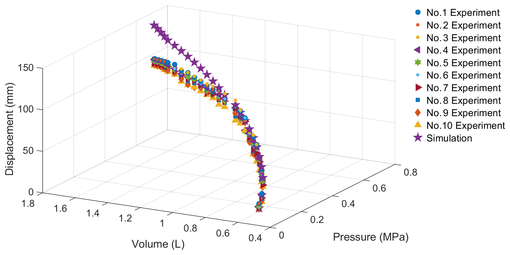
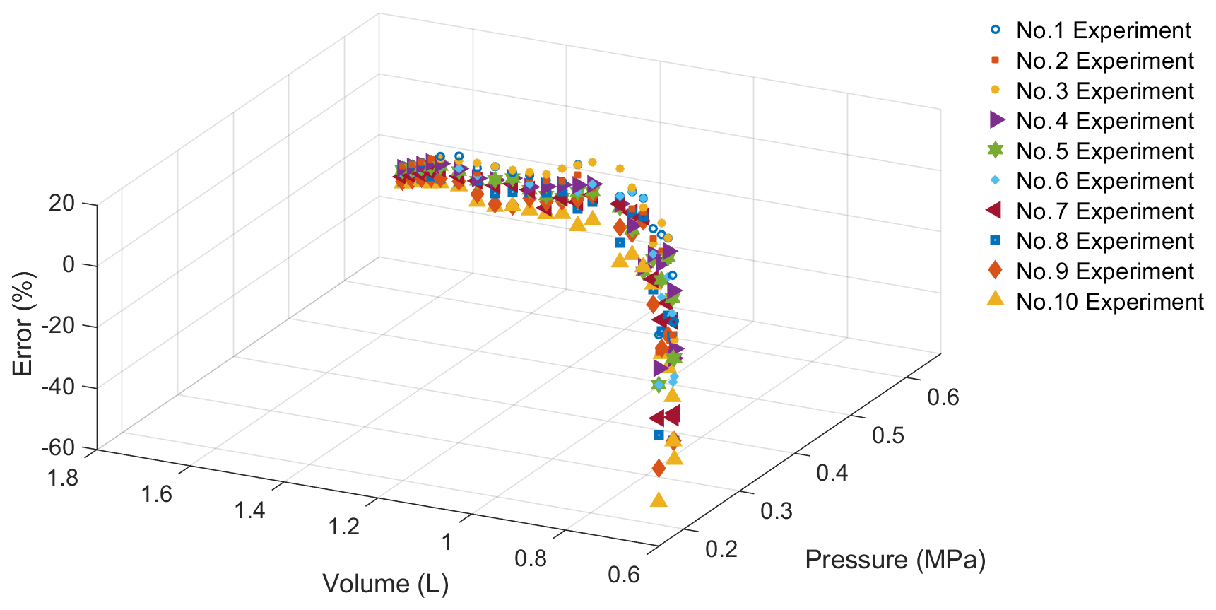
The number of layers of the single actuator used in the experiment was N = 35. The theoretical displacement of the actuator was 245 mm, and the actual maximum displacement was 100 mm. According to the error calculation formula, the following analysis is provided:
where Dexp,Vol (Vol = 0–25) represents the displacement of the tensile experiment, and Dsim,Vol (Vol = 0–25) represents the displacement of the simulation. τtail,Vol (Vol = 0–25) represents the error between the experiment and simulation, as shown in Fig. 17. The maximum error is 51.08 %. The following could be the cause of the error:
-
The material selected for the external skin of the actuator has low tensile resistance and is prone to inelastic deformation after several experiments, which leads to deviations in the experimental results.
-
The loss of air pressure produced by the air pump was due to the actuator's insufficient leakproofness.
3.3 Load experiment and result analysis
The load experiment on the actuator was conducted to characterize the drive power performance and verify the load capacity of the soft pneumatic actuator. During the experiment, the pressure in the actuator was kept constant, while the load was gradually increased. Subsequently, the displacement of the actuator was recorded.
Assuming the additional load of the actuator is Wload, Eq. (37) can be expressed as follows:
The load experimental steps were as follows: at the beginning of the experiment, the voltage of the air pump was 220 V, and the load on the actuator was 0 N. The load on the actuator was gradually increased. The displacement was recorded after continuous pressurization for 5 s each time the load value changed. The loading was ended when the additional load was increased to 30 N. The experimental process was repeated 10 times.
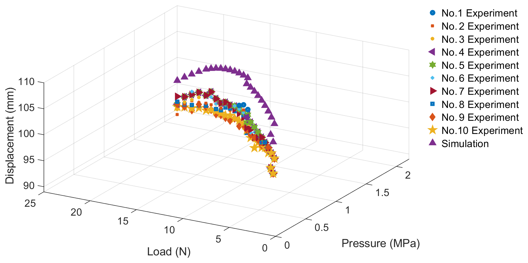

Five sets of experimental data on the contraction displacement and the load value experienced by the actuator were obtained. The data were homogenized to obtain a single set of displacement–load data, which are plotted and shown in Fig. 18. The experimental results demonstrate that when the load is less than 15 N, it scarcely affects the contraction displacement of the actuator. Moreover, once the load exceeds 15 N, the displacement of the actuator decreases as the load increases. The weight of the actuator is measured to be 5 g; thus the force-to-weight ratio can be calculated to be 600 %. In addition, the amount of displacement is proportional to the load when the air pressure inside the actuator is kept constant. Figure 18 also shows the simulation of the load performance of the actuator, and the errors between the simulation and experimental results are calculated as follows:
where Dexp,Loa (Loa = 0–30) represents the displacement of the load experiment, and Dsim,Lod (Vol = 0–30) represents the displacement of the simulation. τloa,Loa (Loa = 0–30) represents the error between the experiment and simulation. As shown in Fig. 19, the maximum error is 15.19 %. Too large a load causes the origami mechanism inside the actuator to produce elastic deformation, which is the root of the problem and causes variations in the load experimental results.
In this paper, inspired by the origami mechanism, a brand-new soft pneumatic actuator was designed based on the tubular cavity origami mechanism. A geometric analysis and stiffness model of the tubular cavity origami mechanism were established. Finite-element simulation software was utilized to simulate the stiffness of the origami mechanism. Subsequently, the simulation results were compared with the stiffness calculation method proposed in this paper as well as other existing methods. The driving control model of the actuator was proposed, and the principle prototype was developed. Tensile and load experiments were conducted. A comparison between the simulation and experimental results shows that the maximum error in the tensile experiment is 51.08 %, and the maximum error in the load experiment is 15.19 %. The axial stiffness and radial stiffness values of the actuator were calculated using the stiffness model for comparison, and it was found that the axial stiffness was considerably greater than the radial stiffness, which proves that the radial motion of the actuator does not affect its axial motion.
Additionally, it has been proven that the stiffness of the origami mechanism is closely related to the angle of the crease. It has been discovered that the method of the origami stiffness model presented in this paper improves the accuracy by 10.09 %.
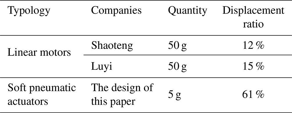
Table 2 compares the actuator presented in this paper with currently available linear actuators. The lightest mass of a linear motor is 50 g, and its maximum displacement ratio is 15 %, while the mass of the soft pneumatic actuator is only 5 g, with a maximum displacement ratio of 61 %. Additionally, the force-to-weight ratio is 600. The outcomes demonstrate that the soft pneumatic actuator designed in this paper has a lower mass and a higher displacement ratio.
Table 2Performance comparison of different types of linear actuators.
This paper suggests that motion models based on the multiple stiffness characteristics of pneumatic actuators should also be developed to achieve multi-degree-of-freedom control of the actuator. The soft pneumatic actuator can be integrated with rehabilitation exoskeleton robotics technology to achieve human–machine coordination and multi-sensory control. Additionally, the soft pneumatic actuator can be applied to industrial robotic arms, gripper robots and other fields.
No data sets were used in this article.
The supplement related to this article is available online at: https://doi.org/10.5194/ms-16-61-2025-supplement.
RX conducted the theoretical research on the origami mechanism and authored the article. QM designed the soft pneumatic actuator. QX and YZ constructed the control system for the soft actuator. CF developed the prototype. VPC performed the simulation. HY designed the experimental methodology.
The contact author has declared that none of the authors has any competing interests.
Publisher’s note: Copernicus Publications remains neutral with regard to jurisdictional claims made in the text, published maps, institutional affiliations, or any other geographical representation in this paper. While Copernicus Publications makes every effort to include appropriate place names, the final responsibility lies with the authors.
The authors would like to acknowledge the financial support from the National Key Research and Development Program of China (2022YFC3601103) and the Natural Science Foundation of Shanghai Municipality (23ZR1444200).
This research has been supported by the National Key Research and Development Program of China (grant no. 2022YFC3601103) and the Natural Science Foundation of Shanghai Municipality (grant no. 23ZR1444200).
This paper was edited by Haiyang Li and reviewed by two anonymous referees.
Chen, Y., Liang, J., Shi, P., Feng, J., Sareh, P., and Dai, J.: Inverse design of programmable Poisson's ratio and in-plane stiffness for generalized four-fold origami, Compos. Struct., 311, 116789, https://doi.org/10.1016/j.compstruct.2023.116789, 2023.
Diller, E., Floyd, S., Pawashe, C., and Sitti, M.: Control of Multiple Heterogeneous Magnetic Microrobots in Two Dimensions on Nonspecialized Surfaces, IEEE T. Robot., 28, 172–182, https://doi.org/10.1109/TRO.2011.2170330, 2012.
Erel, V., Lindsay, A., Singh, I., and Wijesundara, M.: Corrugated Diaphragm Actuator for Soft Robotic Applications, J. Mech. Des.-T. ASME, 144, 045001, https://doi.org/10.1115/1.4052625, 2022.
Feng, N., Liu, L., Liu, Y., and Leng, J. : A bio-inspired, active morphing skin for camber morphing structures, Smart Mater. Struct., 24, 035023, https://doi.org/10.1088/0964-1726/24/3/035023, 2015.
Firouzeh, A. and Paik, J.: An under-actuated origami gripper with adjustable stiffness joints for multiple grasp modes, Smart Mater. Struct., 26, 055035, https://doi.org/10.1088/1361-665X/aa67fd, 2017.
Floyd, S., Diller, E., Pawashe, C., and Sitti, M.: Control methodologies for a heterogeneous group of untethered magnetic micro-robots, Int. J. Robot. Res., 30, 1553–1565, https://doi.org/10.1177/0278364911399525, 2011.
Guan, Q., Sun, J., Liu, Y., and Leng J.: Status of and trends in soft pneumatic robotics, Sci. Sin. Tech., 50, 897–934, https://doi.org/10.1360/SST-2020-0143, 2020 (in Chinese with English abstract).
Hu, Y., Liu, J., Chang, L., Yang, L., Xu, A., Qi, K., Lu, P., Wu, G., Chen, W., and Wu, Y.: Electrically and Sunlight-Driven Actuator with Versatile Biomimetic Motions Based on Rolled Carbon Nanotube Bilayer Composite (Adv. Funct. Mater. 44/2017), Adv. Funct. Mater., 27, 1704388, https://doi.org/10.1002/adfm.201704388, 2017.
Jung, K., Koo, J., Nam, J., Lee, Y., and Choi, H.: Artificial annelid robot driven by soft actuators, Bioinspir. Biomim., 2, S42–S49, https://doi.org/10.1088/1748-3182/2/2/S05, 2007.
Kularatne, R., Kim, H., Boothby, J., and Ware, T.: Liquid crystal elastomer actuators: Synthesis, alignment, and applications, J. Polym. Sci. Pol. Phys., 55, 395–411, https://doi.org/10.1002/polb.24287, 2017.
Kwan, K., Li, S., Hau, N., Li, W., Feng, S., and Ngan, A.: Light-stimulated actuators based on nickel hydroxide-oxyhydroxide, Sci. Robot., 3, eaat4051, https://doi.org/10.1126/scirobotics.aat4051, 2018.
Lamine, H., Laribi, M., Bennour, S., Romdhane, L., and Zeghloul, S.: Design Study of a Cable-based Gait Training Machine, J. Bionic Eng., 14, 232–244, https://doi.org/10.1016/S1672-6529(16)60394-3, 2017.
Lee, D., Kim, J., Sohn, C., Heo, J., and Cho, K.: High-load capacity origami transformable wheel, Sci. Robot., 6, eabe0201, https://doi.org/10.1126/scirobotics.abe0201, 2021.
Li, S., Vogt, D., Bartlett, N., Rus, D., and Wood, R.: Tension Pistons: Amplifying Piston Force Using Fluid-induced Tension in Flexible Materials, Adv. Funct. Mater., 29, 1901419.1–1901419.9, https://doi.org/10.1002/adfm.201901419, 2019.
Liu, J., Wei, J., Zhang, G., Wang, S., and Zuo, S.: Pneumatic Soft Arm Based on Spiral Balloon Weaving and Shape Memory Polymer Backbone, J. Mech. Des.-T. ASME, 141, 082302, https://doi.org/10.1115/1.4042618, 2019.
Meloni, M., Cai, J., Zhang, Q., Lee, D., Li, M., Ma, R., Parashkevov, T., and Feng, J.: Engineering Origami: A Comprehensive Review of Recent Applications, Design Methods, and Tools, Adv. Sci., 8, 2000636, https://doi.org/10.1002/advs.202000636, 2021.
Morgan, J., Magleby, S., and Howell, L.: An Approach to Designing Origami-Adapted Aerospace Mechanisms, J. Mech. Des.-T. ASME, 138, 052301, https://doi.org/10.1115/1.4032973, 2016.
Paez, L., Agarwal, G., and Paik, J.: Design and Analysis of a Soft Pneumatic Actuator with Origami Shell Reinforcement, Soft Robot., 3, 109–119, https://doi.org/10.1089/soro.2016.0023, 2016.
Pagano, A., Yan, T., Chien, B., Wissa, A., and Tawfick, S.: A crawling robot driven by multi-stable origami, Smart Mater. Struct., 26, 094007, https://doi.org/10.1088/1361-665X/aa721e, 2017.
Rodrigue, H., Wang, W., Han, M., Kim, T., and Ahn, S.: An Overview of Shape Memory Alloy-Coupled Actuators and Robots, Soft Robot., 4, 3–15, https://doi.org/10.1089/soro.2016.0008, 2017.
Samper-Escudero, J., Giménez-Fernández, A., Sánchez-Urán, M., and Ferre, M.: A Cable-Driven Exosuit for Upper Limb Flexion Based on Fibres Compliance, IEEE Access, 8, 153297–153310, https://doi.org/10.1109/ACCESS.2020.3018418, 2020.
Shintake, J., Rosset, S., Schubert, B., Floreano, D., and Shea, H.: Versatile Soft Grippers with Intrinsic Electroadhesion Based on Multifunctional Polymer Actuators, Advanced Materials, 28, 231–238, https://doi.org/10.1002/adma.201504264, 2016.
Sun, Z., Li, Y., Zi, B., and Chen, B.: Design, Modeling, and Evaluation of a Hybrid Driven Knee-Ankle Orthosis With Shape Memory Alloy Actuators, ASME J. Mech. Des, 145, 063301, https://doi.org/10.2139/ssrn.4052263, 2023.
Wang, Y., Jin, M., and Liu, S.: Design and Application of Muscle-tendon System-like Soft Actuator, Chin. Hydraul. Pneum., 46, 146–151, https://doi.org/10.11832/j.issn.1000-4858.2022.05.017, 2022.
Weng, M., Zhou, P., Chen, L., Zhang, L., Zhang, W., Huang, Z., Liu, C., and Fan, S.: Actuators: Multiresponsive Bidirectional Bending Actuators Fabricated by a Pencil-on-Paper Method (Adv. Funct. Mater. 40/2016), Adv. Funct. Mater., 26, 7368–7368, https://doi.org/10.1002/adfm.201670266, 2016.
Xiloyannis, M., Chiaradia, D., Frisoli, A., and Masia, L.: Physiological and kinematic effects of a soft exosuit on arm movements, J. Neuroeng. Rehabil., 16, 29, https://doi.org/10.1186/s12984-019-0495-y, 2019.
Yang, H., Yeow, B., Li, Z., Li, K., Chang, T., Jing, L., Li, Y., Ho, J., Ren, H., and Chen, P.: Multifunctional metallic backbones for origami robotics with strain sensing and wireless communication capabilities, Sci. Robot., 4, eaax7020, https://doi.org/10.1126/scirobotics.aax7020, 2019.
Yu, Y. and Luo, Y.: Bucking analysis of structures by the finite particle method, Eng. Mech., 26, 23–29, 2009.
Zhakypov, Z. and Paik, J.: Design Methodology for Constructing Multimaterial Origami Robots and Machines, IEEE T. Robot., 34, 151–165, https://doi.org/10.1109/TRO.2017.2775655, 2018.
Zhang, Y., Zhang, Q., Cheng, Y., Su, H., Kecorius, S., Wang, Z., Wu, Z., Hu, M., Zhu, T., Wiedensohler, A., and He, K.: Measuring the morphology and density of internally mixed black carbon with SP2 and VTDMA: new insight into the absorption enhancement of black carbon in the atmosphere, Atmos. Meas. Tech., 9, 1833–1843, https://doi.org/10.5194/amt-9-1833-2016, 2016.