the Creative Commons Attribution 4.0 License.
the Creative Commons Attribution 4.0 License.
 | 16 Sep 2025
Meshing characteristics of variable hyperbolic circular-arc tooth trace cylindrical gears with cutter errors
Dengqiu Ma
Jianbing Long
Zhenglong Zhu
We investigate the relationship between cutter errors and meshing characteristics of the variable hyperbolic circular-arc tooth trace (VH-CATT) cylindrical gears. Firstly, based on the tooth surface forming principle, the tooth surface mathematical model with cutter errors is derived. Next, the mathematical models of tooth contact analysis and load tooth contact analysis are developed to calculate the contact trace, load transmission error, tooth surface load, and load distribution coefficient. Then, the equation of the tooth surface contact ellipse and the formulas of the main curvature direction angle are derived. Finally, the influences of the cutter errors on the contact ellipse, tooth surface contact trace, load transmission error, tooth surface load, and load distribution coefficient are analyzed. The research shows that all of the cutter errors have a certain influence on the contact ellipses, except for the translation error Δx. The rotation angle error γ and the translation error Δy make the contact position deviate from the middle section; all the cutter errors have a certain influence on the actual meshing line, except for the translation error Δx and the tooth line radius error ΔRT. The rotation angle error γ and the tooth line radius error ΔRT have a bigger influence on the maximum load; the cutter errors mainly affect the load distribution coefficient of the single-tooth meshing area. Except for the tooth line radius error ΔRT, all cutter errors make the amplitude of the load transmission error increase. These research results are helpful for the performance improvement and service life study of the VH-CATT cylindrical gears.
- Article
(5872 KB) - Full-text XML
- BibTeX
- EndNote


Gear transmission is one of the main forms of mechanical transmission and is widely used in the automotive, mining, and aviation industries (Dongu et al., 2025; Wang et al., 2025; Ke et al., 2025). Research shows that the machining accuracy of the gear transmission is crucial for the service life, safety, reliability, and costs of operation and maintenance of the equipment (Dai et al., 2023). Generally, the machining accuracy of gear transmission is directly affected by the accuracy of gear-machining machine tools – for example, the geometric errors and thermal deformation errors of machine tools. The reference shows that the geometric errors and thermal deformation errors of the machine tools account for approximately 60 % to 70 % of the errors that affect the machining accuracy of the machine tools (Yang et al., 2024). Therefore, to improve the service life of the mechanical transmission system and effectively control the transmission performance of the system, it is of great significance to study the machining accuracy of gears and to identify the relationship between the machining accuracy of gears and the quality of gear transmission performance (Ren, 2019).
Machine tools, cutting tools, and gear blanks are three important components of the gear machining, and the cutting tools are in direct contact with the gear blanks. Due to the existence of machine tool errors, thermal deformation errors, etc., the actual movement trajectory of the cutting tool deviates from the theoretical movement trajectory. The actual tooth surface obtained through machining has a certain deviation compared with the ideal tooth surface, which directly affects the machining quality of the gears (Sun, 2018). At present, lots of achievements have been made in the research into the machine tool errors of the gear-machining system. The main method is to convert the machine tool errors into the pose errors of the cutting tool relative to the workpiece based on the multi-body system theory. For example, Yao and Hong (2022) proposed a modeling method for the mapping relationship between machine tool errors and gear errors, and the research found that the profile deviation and helix deviation are in a direct proportional relationship with the deflection errors of the y and z axes. Yang et al. (2022) proposed a full-process method for the spiral bevel gears directly aimed at free-form machine tools and analyzed the influence law of each of the axis motion errors of the machine tool on the topological shape of the pinion tooth surface. Li et al. (2023a) proposed a method for identifying the key geometric errors of the machine tools based on the combination of the tooth surface pose geometric error model and the Sobol method. The research results show that this method can effectively identify the key error items of large-scale gear hobbing machines. Yang et al. (2019) analyzed the sensitivity of the normal profile error of the gear skiving to various geometric pose errors and presented the error correction method. Li et al. (2023b) proposed and optimized a new tooth surface error model of spiral bevel gear considering the error of the machine tool moving axis to obtain higher tooth surface accuracy and meshing efficiency based on the theory of the multi-body dynamics system and the principle of gear meshing. Li et al. (2023c) established the tool comprehensive error model and the tooth surface error model to reveal the mapping rules between the geometric errors and the tooth surface errors of face gear. Song et al. (2022) established a mathematical model of this type of gear pair to investigate the influence of different machine tool setting errors on the mesh behavior of small-module spiral bevel gear. Tang et al. (2022) proposed an innovative geometric error compensation method for the machining with non-rotary cutters based on two main points. Rituraj et al. (2019) proposed a technique to study the operation of external gear machines (EGMs), accounting for two common gear manufacturing errors: conicity and concentricity. Yang et al. (2018) proposed a definition and calculation process of tooth surface deviations along the tooth trace and profile directions for beveloid gear to investigate the effects of the machine tool adjustment errors on tooth surface deviations and contact characteristics. The above-mentioned research achievements provide a powerful guarantee for improving the machining accuracy of gears and extending the service life of mechanical equipment. At the same time, it also provides a technical foundation for the research into the relationships between the machining accuracy, transmission performance, and service life of variable hyperbolic circular-arc tooth trace (VH-CATT) cylindrical gears.
The VH-CATT cylindrical gear is a kind of cylindrical gear, and it is similar to the herringbone gear. It combines the advantages of the spur gear, helical gear, and herringbone gear transmissions and has a promising application prospect. At present, researchers have carried out a large number of studies on the VH-CATT cylindrical gear and achieved abundant research results, which mainly focus on the analysis of the meshing performances (Ma et al., 2021; Liu and Ma, 2022; Ma et al., 2024a, b, 2023a; Wei et al., 2024a; Wu et al., 2023). The research content also involves the analysis of the machine tool errors and transmission performance of the VH-CATT cylindrical gear. However, the research is not in-depth, and some fields have not been covered. The research content regarding the machine tool errors is stated as follows. Wei et al. (2024b) established the structure model and coordinate system of the VH-CATT gear machine tool to analyze the influence of different machine tool errors on the geometric contact characteristics of the gear pair. However, it does not involve gear dynamics, and it does not derive the mathematical model of the tooth surface with errors. Liang et al. (2023) established a machine tool coordinate system, derived a motion transfer matrix to establish an error model for the tooth surface, and derived the equation for the tooth surface with an error term. Liang et al. (2022) also proposed a Kriging model based on the glowworm swarm optimization algorithm of scene understanding to study the relationship between input parameters and output precision; this provides an optimization strategy of gear-machining accuracy and a theoretical basis for the promotion of the VH-CATT cylindrical gear. Wu et al. (2020a) established a comprehensive error model for the machining of CATT cylindrical gears based on the topological structure model and transformation matrices. Wu et al. (2020b) described the overall machine tool error through the position errors of the gear blank and the cutter head, as well as the shape error of the cutting tool, and deduced the tooth surface equation, including the machine tool error, based on the meshing principle. Tian et al. (2019) comprehensively considered the errors of various components of the machine tool and established an error analysis model of the motion chain of the machining machine tool based on the theory of multi-body dynamics. Ma et al. (2023b) analyzed the error sources of tooth-forming accuracy based on the forming principle of the VH-CATT cylindrical gear to investigate the influences of the cutter errors on the tooth thickness error and gear contact. According to current references, the research on the meshing characteristics of the VH-CATT cylindrical gears with cutter errors is not in-depth; it has not yet covered the load transmission error (LTE), the load distribution on the tooth surface, the contact ellipse of the tooth surface, etc. However, the geometric characteristics of the VH-CATT cylindrical gears are complex. When there is an error in the cutter, it will further aggravate the complexity of the tooth surface geometric characteristics and then affect the dynamic contact characteristics of the gear; it will bring uncertainty into the service life of the VH-CATT cylindrical gears. Therefore, it is important to study the relationship study between cutter errors and meshing characteristics.
Therefore, a study of the meshing characteristics of the VH-CATT cylindrical gears with cutter errors is proposed. In the present paper, in Sect. 1, a coordinate system for tooth surface formation with cutter errors is established to derive the tooth surface equation with cutter errors. In Sect. 2, the tooth contact analysis model (TCA) and load tooth contact analysis (LTCA) model are established, and the formulas of the tooth surface contact ellipse and the main curvature direction angles are derived. In Sect. 3, the influences of the cutter errors on the contact ellipses, the tooth surface contact trace, and the loaded contact characteristics are analyzed. The research results are helpful for the performance improvement and service life study of the VH-CATT cylindrical gears.
In the processing of the VH-CATT cylindrical gears, due to factors such as manufacturing errors, installation errors, thermal deformation, and wear of the machining equipment, the motion trajectory of the tooth-surface-forming cutter edge will deviate from the theoretical position. That is, there are forming errors on the tooth surface of the VH-CATT cylindrical gears obtained from processing. To study the influence of the tooth-surface-forming errors of VH-CATT cylindrical gears on the meshing performance, factors such as machine tool manufacturing errors, installation errors, thermal deformation, and wear are transformed into the cutter position errors and the cutter edge geometric errors of the VH-CATT cylindrical gear, which are collectively referred to as cutter errors. On this basis, a mathematical model of the VH-CATT cylindrical gear with cutter errors is established.
Figure 1 is a tooth surface formation diagram of the VH-CATT cylindrical gear with cutter errors. In the figure, Δα is the pressure angle error, ΔRT is the tooth line radius error, Δx is the translation error along the x axis, Δy is the translation error along the y axis, Δz is the translation error along the z axis, γ is the rotation error around the x axis, and β is the rotation error around the y axis. Because the rotational error of the cutter around the cutter spindle (z axis) is in the rotational direction of the cutter during the gear processing, it theoretically has no impact on the gear forming accuracy.
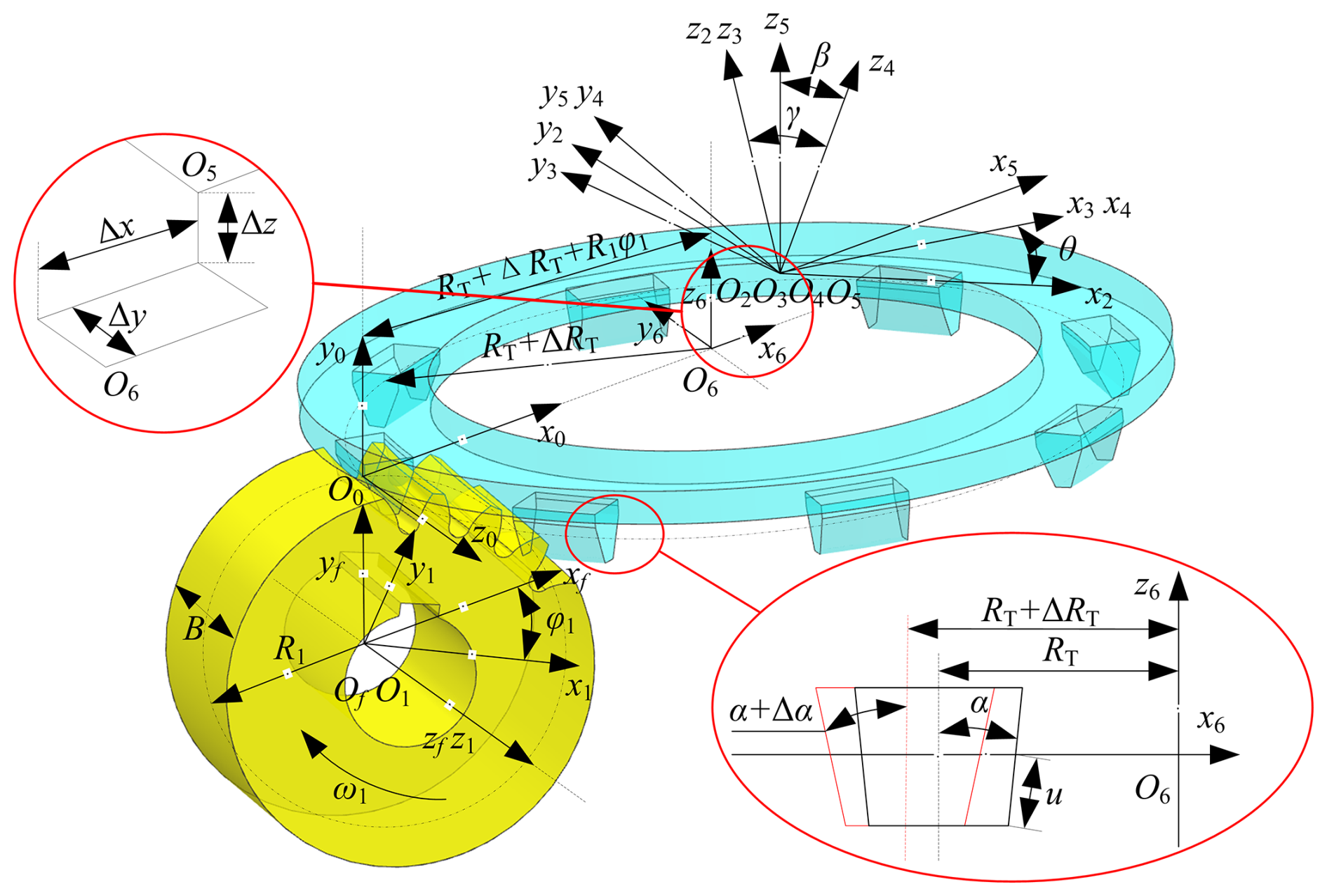
Moreover, O1x1y1z1 is the moving coordinate system of the gear blank, which moves along with the gear blank; O2x2y2z2 is the moving coordinate system of the cutter, which moves along with the cutter; O3x3y3z3 is the stationary coordinate system of the cutter; Ofxfyfzf is the stationary coordinate system of the gear blank; and O0x0y0z0 is the intermediate auxiliary coordinate system. O5x5y5z5 is the coordinate system of the cutter actual position, and O6x6y6z6 is the static coordinate system of the cutter theoretical position. The positional relationship between the origin of O6x6y6z6 and that of O5x5y5z5 represents the translation errors Δx, Δy, and Δz of the cutter position error along the x, y, and z axes. O4x4y4z4 is the coordinate system when there is a rotational angle error around the y axis at the cutter theoretical position, representing the rotational position error β of the cutter head around the y axis. The positional relationship between O4x4y4z4 and O3x3y3z3 represents the rotational position error γ around the x axis. RT is the tooth line radius, R1 is the pitch circle radius, B is the gear width, α is the pitch circle pressure angle, ω1 is the rotational speed of the gear blank, θ is the spreading angle of the cutter head, and ϕ1 is the involute angle of the tooth profile. u is the distance from any point on the cutter edge contour to the x axis along the cutter edge. This is positive when the point is on the positive semi-axis of the z axis and negative when the point is on the negative semi-axis of the z axis.
To establish the tooth surface mathematical model, the cutter equation with errors in O2x2y2z2 is written as follows:
where eRT = RT+ΔRT, eα = α+Δα, and “±” represents the tool cutter edge outside and inside.
The cutter equation with errors in O3x3y3z3 could be written as follows:
According to Eq. (2), the normal vector of tool surface with errors is expressed as follows:
The relative speed with errors evdg in O3x3y3z3 can be expressed as follows:
where is the rotation angular speed with cutter errors, with = 0; evd is the translation speed with cutter errors, with evd = ω1R1i3; and is the rotation angular speed with cutter errors of the gear blank. The specific expression of is as in Eq. (5), and eE3 is the expression of O3 to O1. The specific expression of eE3 is as in Eq. (6).
Combining Eqs. (2), (4), (5), and (6), evdg can be calculated.
According to the gear meshing principle (Litvin, 2008), the common normal line of the contact point between the cutter edge's revolving surface and the gear tooth surface is perpendicular to the relative velocity at this point, as shown in Eq. (7). Based on this condition, the meshing conditions eu can be solved.
According to the gear geometry, the expression of the contact point between the cutter and the gear blank in O1x1y1z1 is the tooth surface equation. By means of the coordinate transformation from O3x3y3z3 to O1x1y1z1, the tooth surface equation can be expressed as follows:
According to the spatial geometric positional relationships among various coordinate systems, the expression of eM13 is as in Eq. (9).
Combining Eqs. (2), (7), (8), and (9), the tooth surface equation with cutter errors can be expressed as follows:
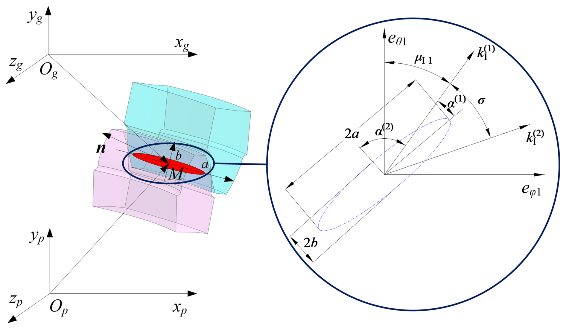
Figure 2 shows the meshing and contact situation of the VH-CATT cylindrical gear pair. In the figure, Opxpypzp is the coordinate system of the driving gear, Ogxgygzg is the coordinate system of the driven gear, and M point is the contact point of the tooth surface. n is the common normal vector of the contact point. Since the tooth surface is a continuous tangent, the driving gear and driven gear have the same position vector and common normal vector at the meshing point in the same coordinate system. If Opxpypzp is taken as a fixed coordinate system, the same position vector and common normal vector at the meshing point can be expressed as in Eq. (11). Eq. (11) is also called the TCA model.
Here, ψ1 is the meshing angle of the driving gear, ψ2 is the meshing angle of the driven gear, θ1 is the spreading angle of the driving gear, ϕ1 is the tooth profile involute angle of the driving gear, θ2 is the spreading angle of the driven gear, ϕ2 is the tooth profile involute angle of the driven gear, is the driving-gear tooth surface, is the driven-gear tooth surface, is the driving-gear tooth surface normal vector, and is the driven-gear tooth surface normal vector.
Solving Eq. (11), we can obtain the trajectory and geometric transmission error during the gear meshing process. Equation (12) is the expression of the geometric transmission error ϕTE.
Here, ϕ10 is the initial angular displacement of the driving gear, ϕ2(ϕ10) is the initial angular displacement of the driven gear, z1 is the teeth number of the driving gear, and z2 is the teeth number of the driven gear.
In Fig. 2, the red contact ellipse around point M is the real contact area of the tooth surface under load, a is the major axis of the contact ellipse, and b is the minor axis of the contact ellipse. Point M is at the center of the contact ellipse. According to Ma et al. (2021), the contact ellipse's major axis a and minor axis b can be calculated based on Eqs. (13) to (18), and the meanings of parameters in the equation can be found in Ma et al. (2021).
For an ideal gear pair, the contact ellipse's major axis is in the direction of the tooth line, and the meshing point is located at the mid-section of the tooth width. However, when there is a form error on the tooth surface, there may be a certain angle between the major axis of the contact ellipse and the direction of the tooth trace; the position of the meshing point may deviate from the mid-section of the tooth width, which will affect the meshing performance of the gear pair. The following content is used to derive the calculation formula for the angle between the contact ellipse's major axis and the direction of the tooth trace.
As shown in Fig. 3, this represents a spatial surface, denoted as r (θ,ϕ). M is a certain point in space. eθ and eϕ are the tangent lines of the two coordinate curves on the surface. T is the direction of an infinitesimal displacement for a point along the surface, and it is one of the main directions of the surface. μ is the angle from eθ to T, and ν is the angle from eθ to eϕ. According to Fig. 3, the following relationships exist:
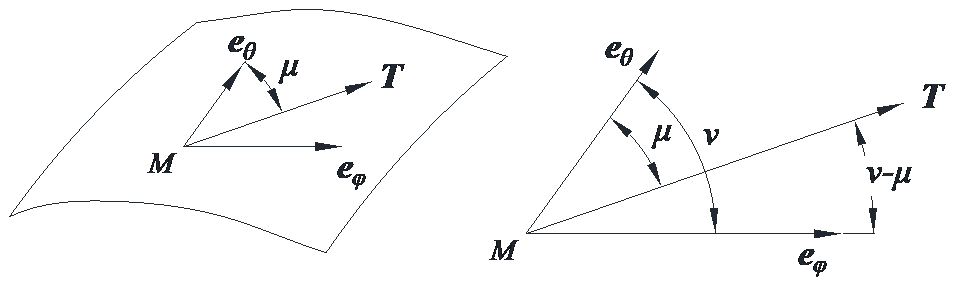
According to Litvin (2008), the normal curvature equation at point M on the surface is as in Eq. (21).
Here, r represents the tooth surface equation, the subscript θ denotes the partial derivative with respect to θ, and the subscript ϕ denotes the partial derivative with respect to ϕ.
Taking the derivative of Eq. (21) with respect to μ and setting it to be equal to 0, Eq. (22) can be obtained.
Solving Eq. (22) can bring about two solutions, μ1 and μ2; these two solutions represent the two main directions of the surface curvature. Moreover, there is a 90° difference between μ1 and μ2, which indicates that the main curvature directions are perpendicular to each other. Calculations indicate that the main curvature directions are in the same direction as eθ and eϕ when there is no error, namely, μ1≈0 and μ2≈0.5π.
Figure 4 shows the relationship between the main curvatures of the tooth surfaces of the driving and driven gears. is one of the main curvatures of the driving gear's tooth surface, is the second main curvature of the driving gear's tooth surface, is one of the main curvatures of the driven gear's tooth surface, is the second main curvature of the driven gear's tooth surface, and the angle from to is the directed angle σ.
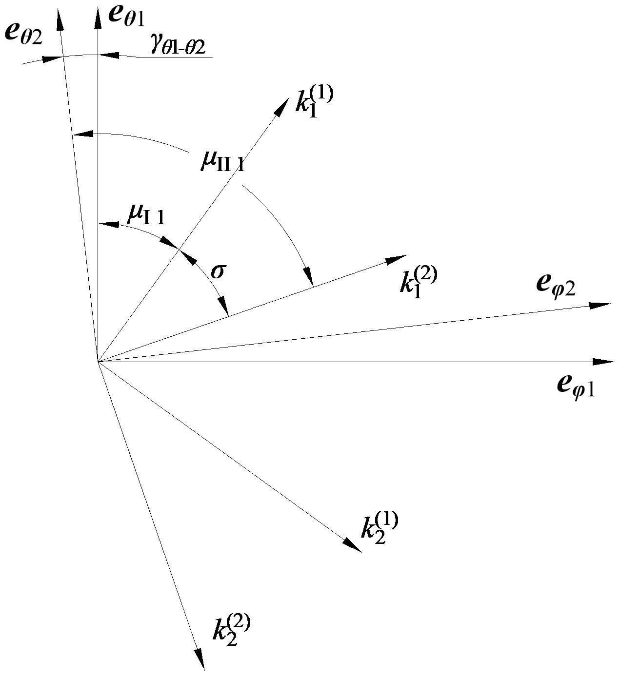
According to Fig. 4, there is a relationship, as shown in Eq. (23).
Here, μII1 is the angle from the direction of to eθ2, μI1 is the angle from the direction of to eθ1, and γθ1−θ2 is the angle from eθ2 to eθ1.
Then, the main curvature direction angles of the driving and driven gears' tooth surfaces for the VH-CATT cylindrical gear can be expressed using Eq. (25). It is specified that the counter-clockwise direction is taken as positive, while the clockwise direction is taken as negative.
LTCA is an important technical means for the dynamic performance analysis of gears. It can be used to obtain tooth surface loads, load distribution coefficients, LTE, etc. Furthermore, it is widely applied to the meshing dynamics analysis of various types' gears. Equation (26) is the deformation compatibility equation at any contact point j.
Here, dj is the remaining gap of the tooth surface if dj = 0 and Fj > 0 or if dj > 0 and Fj = 0, and fjk and are the flexibility coefficients of the driving gear and driven gear, respectively. wj is the tooth surface gap of the j point, Fk is the load at the k point, and sz is the normal displacement of the driven gear under external load.
According to Ma et al. (2024a), based on the conditions of deformation coordination, force balance, and non-embedding, the following mathematical model is established to describe the equilibrium state of tooth contact under load:
where P is the tooth surface load, P = [FI,andFII]. j = . I and II represent the first and second pairs of teeth, respectively. S is the flexibility matrix of the tooth contact point, S = [SI 0;0 FII]. F is the load matrix of the tooth contact point. w is the initial clearance matrix. d is the residual clearance matrix. nI and nII are the unit normal vectors of the first and second pairs of teeth. diI and diII are the matrixes composed of the rotation radius of discrete points on the contact line. e is the unit diagonal matrix.
Based on Eq. (27), the calculation formulas of the LTE φLTE and load distribution coefficients Lm can be expressed as in Eq. (28) and (29).
Here, r2c is the vector from the rotation center of the driven gear to the contact point of the tooth surface, is the unit vector of the driven gear rotation axis direction, and ng is the unit vector of the common normal direction of the VH-CATT cylindrical gear system.
Figures 5, 6, 7, 8, 9, and 10 show the influence of the cutter errors on the contact ellipses. The main parameters are as follows: modulus m = 8 mm, pressure angle α = 20°, gear numbers z1 = 29 and z2 = 41, and tooth line radius RT = 200 mm. Figure 5 shows the influence of ΔRT on the contact ellipse; ΔRT is equal to 5 and 10 mm. Observing Fig. 5, the contact ellipse's major axis increases with an increase in ΔRT, but ΔRT has no influence on the contact ellipse's minor axis. The reason for this is that the tooth line radius increases, the tooth surface clearance decreases, and the contact ellipse's major axis increases. However, changes in the tooth line radius do not affect the curvature characteristics of the tooth surface in the direction of the tooth profile. Therefore, the contact ellipse's minor axis remains unchanged.
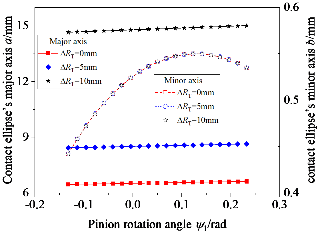
Figure 6 shows the influence of Δα on the contact ellipse; Δα is equal to −2, −1, 1, and 2°. Observing Fig. 6, the contact ellipse's major axis decreases with an increase in Δα and gradually increases from the tooth root to the tooth top when Δα is less than zero; the contact ellipse's major axis increases with an increase in the Δα and gradually increases from the tooth root to the tooth top when Δα is greater than zero. The contact ellipse's minor axis decreases with an increase in Δα when Δα is less than zero; the contact ellipse's minor axis increases with an increase in Δα when Δα is greater than zero.
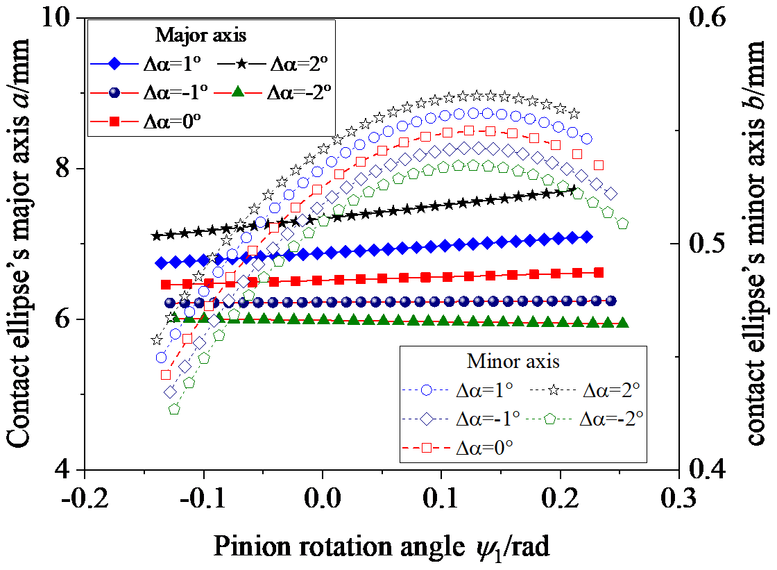
Figure 7 shows the influence of γ on the contact ellipse; γ is equal to 0.1, 0.3, and 0.5°. Observing Fig. 7, the change law of the contact ellipse's major axis is relatively complex. The contact ellipse's major axis increases with an increase in γ in the area close to the tooth root and decreases with an increase in γ in the area close to the tooth top; the contact ellipse's major axis gradually decreases from the tooth root to the tooth top. As for the contact ellipse's minor axis, the contact ellipse's minor axis increases with an increase in the γ, but the range of change is not significant.
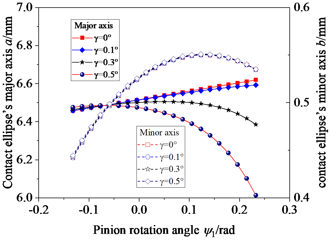
Figure 8 shows the influence of β on the contact ellipse; β is equal to −2, −1, 1, and 2°. Observing Fig. 8, the contact ellipse's major axis increases with an increase in β when β is less than zero and decreases with an increase in β when β is greater than zero; the contact ellipse's major axis gradually increases from the tooth root to the tooth top. The contact ellipse's minor axis increases with an increase in β when β is less than zero and decreases with an increase in β when β is greater than zero, but the range of change is not significant.
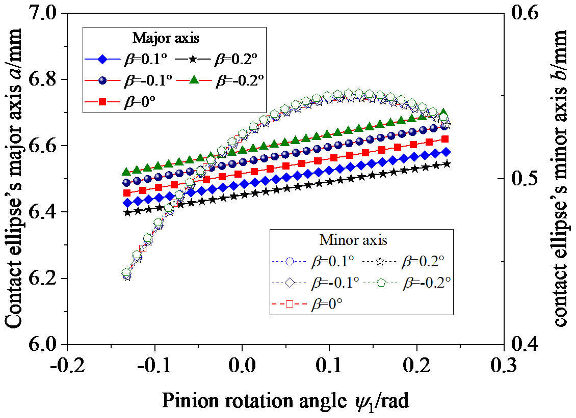
Figure 9 shows the influence of Δy on the contact ellipse; Δy is equal to 1 and 2 mm. Observing Fig. 9, the contact ellipse's major axis decreases with an increase in Δy, and the magnitude of change in the contact ellipse's major axis is relatively large in the area close to the tooth top; the contact ellipse's major axis gradually decreases from the tooth root to the tooth top. The contact ellipse's minor axis increases with an increase in Δy, except in the area close to the tooth top.
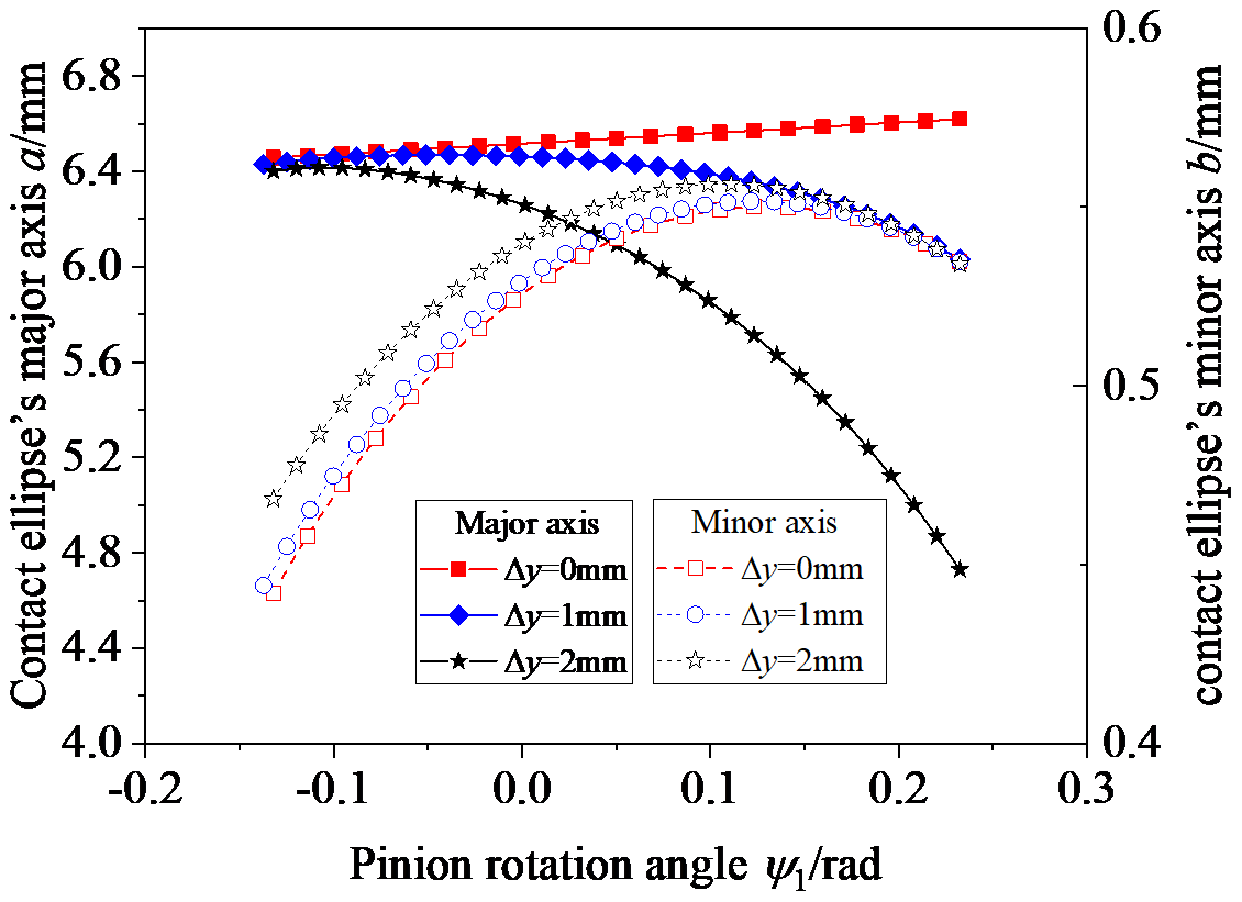
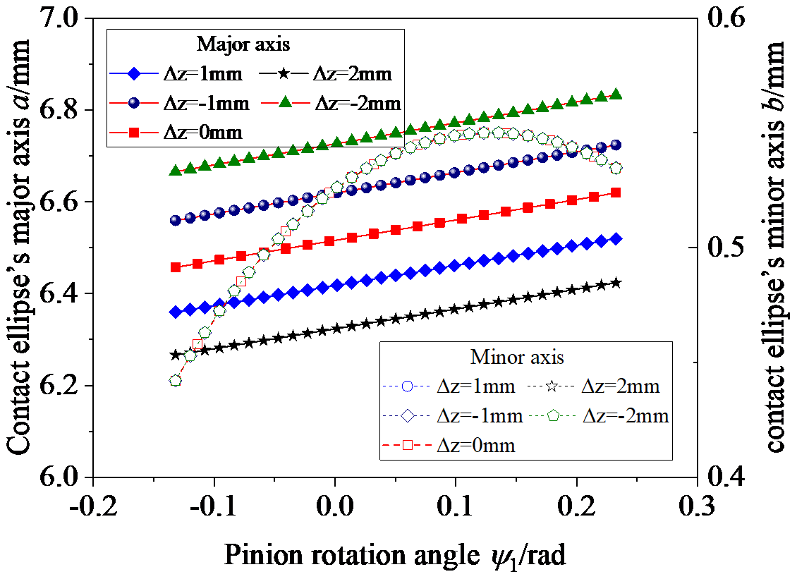
Fig. 10 shows the influence of Δz on the contact ellipse; Δz is equal to 2, 1, 1, and 2 mm. Observing Fig. 10, the contact ellipse's major axis increases with an increase in Δz when Δz is less than zero and decreases with an increase in Δz when Δz is greater than zero. Δz has no influence on the contact ellipse's minor axis.
As for the translation error Δx, according to Ma et al. (2023b), the translation error Δx has no impact on the structure characteristics of the VH-CATT cylindrical gear. The 3D model of the VH-CATT cylindrical gear with the translation error Δx is rotated by an angle compared to the ideal 3D model. When the 3D model of the VH-CATT cylindrical gear with the translation error Δx is rotated in the opposite direction by the same angle, the two models will completely overlap. That is, theoretically, the translation error Δx also has no impact on the contact ellipses, and so it will not be discussed in detail.
The tooth line radius has an important influence on the contact form of the VH-CATT cylindrical gear. Theoretically, when the tooth line radius of the driven gear is larger than that of the driving gear, the VH-CATT cylindrical gear's contact form is a “bridge-type” contact; that is, the actual contact point is at the edge of the tooth width. However, Ma et al. (2019) show that the tooth thickness gradually decreases from the middle section to the tooth width edge, and the tooth surface clearance gradually increases for the VH-CATT cylindrical gear. However, the tooth thickness also increases with an increase in the tooth line radius. That is, when the decrease in the amplitude of the tooth thickness from the middle section to the end face is greater than the increase in the amplitude of the tooth thickness caused by the tooth line radius error, the gear contact occurs in the middle section of the tooth width. Otherwise, the contact occurs at the edge of the tooth width. According to Litvin (2008), the mathematical model of the edge contact is as in Eq. (30).
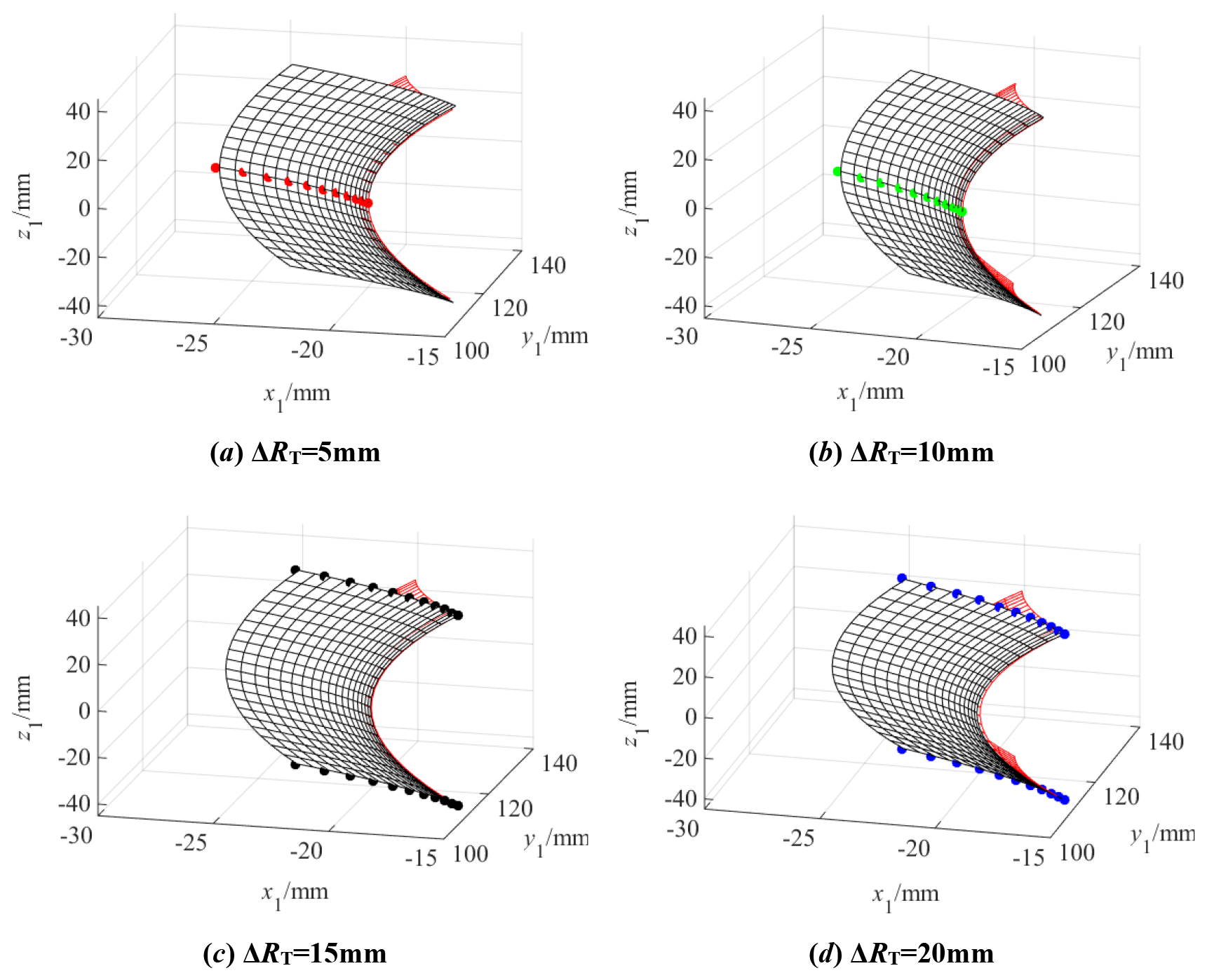
Figure 11 shows the tooth surface contact position when there is a tooth line radius error ΔRT. Figure 12 shows the actual tooth surface contact trace with ΔRT. It can be seen from the figures that, when ΔRT is equal to 5 and 10 mm, ΔRT has no effect on the contact position; when ΔRT is equal to 15 and 20 mm, the contact points are a series of points on the two edges of the tooth width, and the gear contact form becomes “bridge-type” contact. When ΔRT is equal to 5 and 10 mm, the meshing line is a straight line in the middle section. When ΔRT is equal to 15 and 20 mm, the meshing line is two straight lines at the edge of the gear width. Through calculation analysis, it can be seen that the length of the actual meshing line does not change when the contact position is in the middle section of the tooth width.
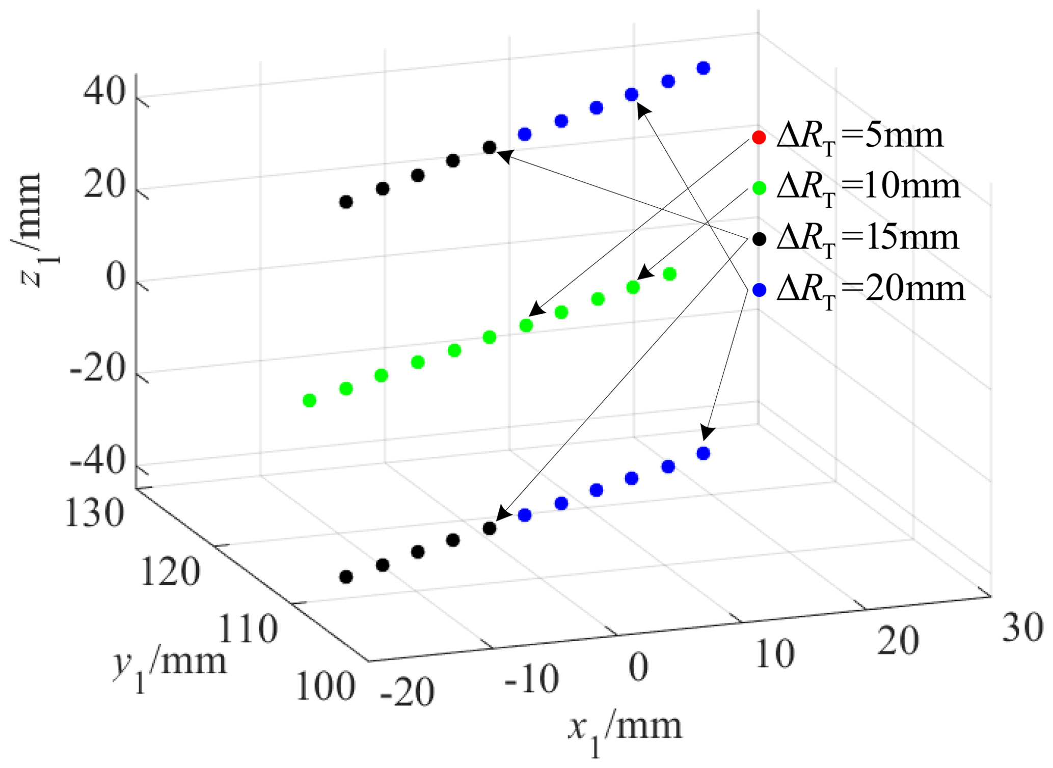
Figure 13 shows the tooth surface contact position when there is a pressure angle error Δα, and Fig. 14 shows the actual tooth surface contact trace with Δα. Observing Fig. 13, no matter how the pressure angle error changes, the position of the tooth surface contact point is always in the middle section of the tooth width. However, it can be seen from Fig. 14 that the actual tooth surface contact trace with Δα has changed. When Δα is greater than 0, the length of the actual meshing line decreases, and, otherwise, the actual meshing line increases.

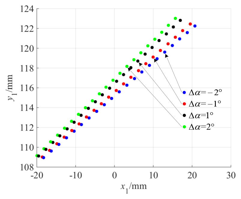
The reason for this is as follows: when Δα is greater than 0, the tooth thickness of the gear root increases, and the tooth thickness of the gear top decreases. To ensure normal contact between the driving gear and the driven gear, the driving gear needs to rotate over a larger angle in the initial meshing stage and a smaller angle in the disengaging meshing stage. When Δα is less than 0, the variation rule is opposite. The rotation angle is small at the beginning of contact and large when disengaging from meshing. However, the turning radius of the contact point in the disengaging meshing stage is larger than that in the initial meshing stage. According to dl=rdθ, it can be seen that the actual meshing line is longer when Δα is less than 0.
Figure 15 shows the tooth surface contact position when there is a rotational angle error γ around the x axis, and Fig. 16 shows the actual tooth surface contact trace with a rotational angle error γ around the x axis. As can be seen from the figures, the position of the tooth surface contact point deviates from the middle section of the tooth width as the rotational angle error γ around the x axis increases, and it gradually moves away from the middle section of the tooth width from the gear root to the gear top. The larger the rotational angle error γ around the x axis is, the greater the deviation degree of the position of the tooth surface contact point is. The reason for this is that, when there is a rotational angle error γ around the x axis, the width of the tooth groove in the z-axis positive semi-axis direction of the gear decreases. Moreover, the larger the rotational angle error γ around the x axis is, the smaller the width of the tooth groove is. That is, the clearance between the tooth surfaces at the far end of the tooth width in the z-axis positive semi-axis direction decreases, causing the tooth surface contact point to gradually move away from the middle section of the tooth width from the gear root to the gear top. At the same time, the calculations show that the length of the actual meshing line decreases slightly with an increase in the rotational angle error γ around the x axis.
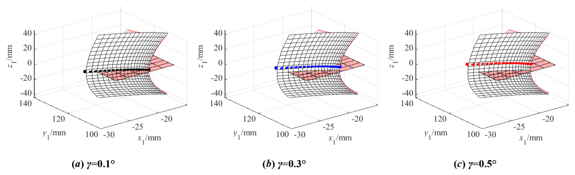
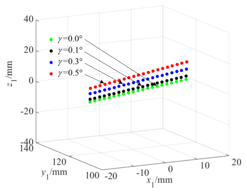
Figure 17 shows the tooth surface contact position when there is a rotational angle error β around the y axis, and Fig. 18 shows the actual tooth surface contact trace with rotational angle error β around the y axis. It can be seen that the contact position of the tooth surface is entirely in the middle section of the tooth width. At the same time, the calculations show that the lengths of the actual meshing lines change slightly with an increase in the rotational angle error β around the y axis.
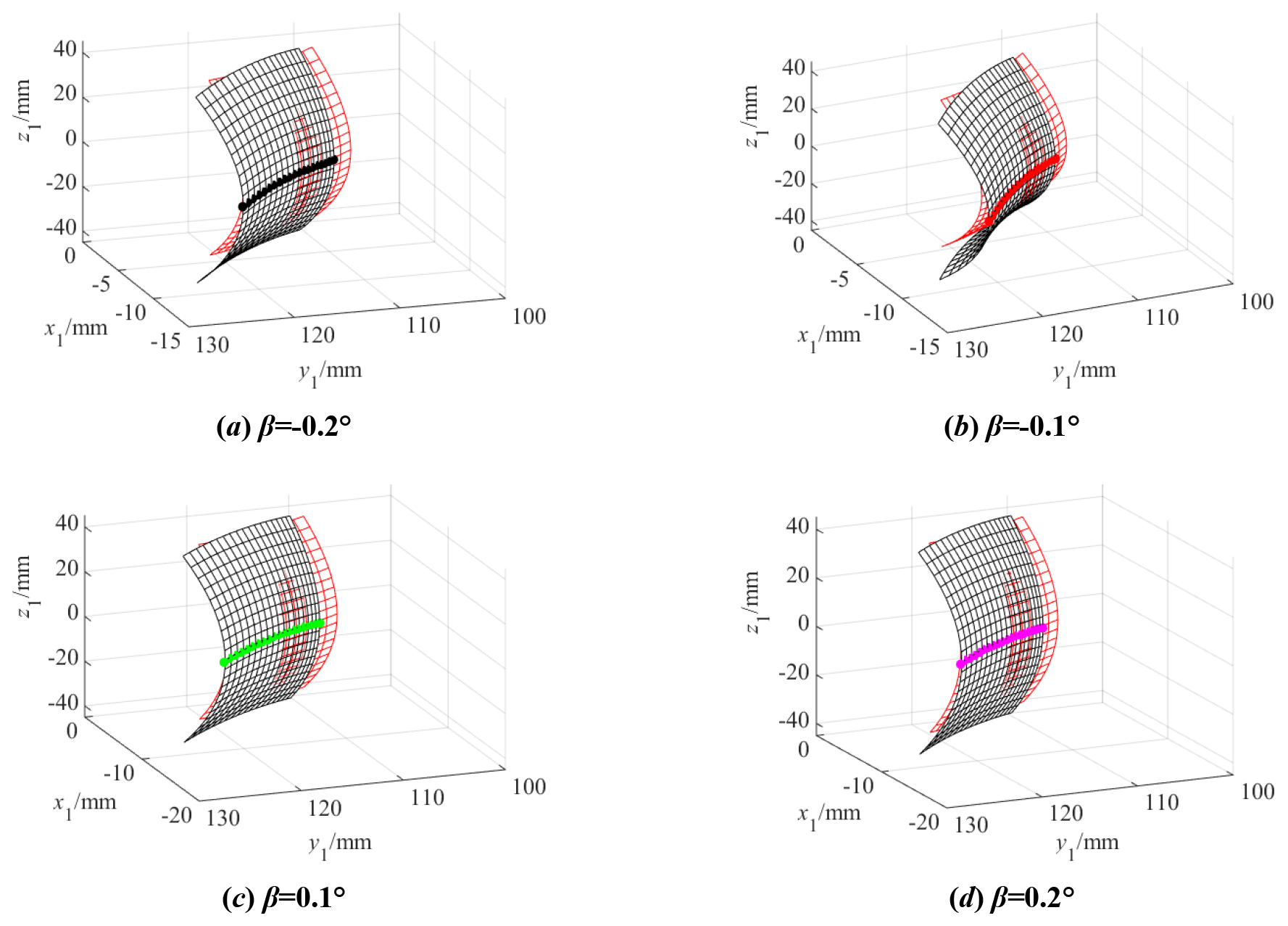
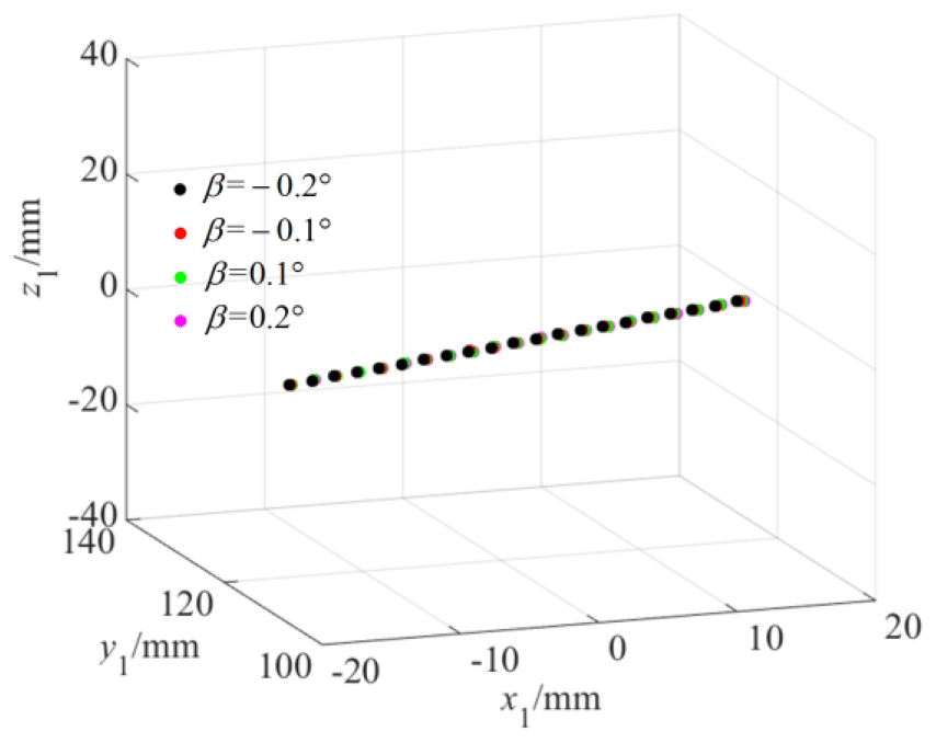
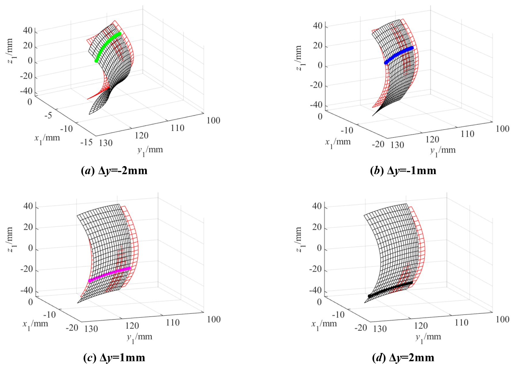
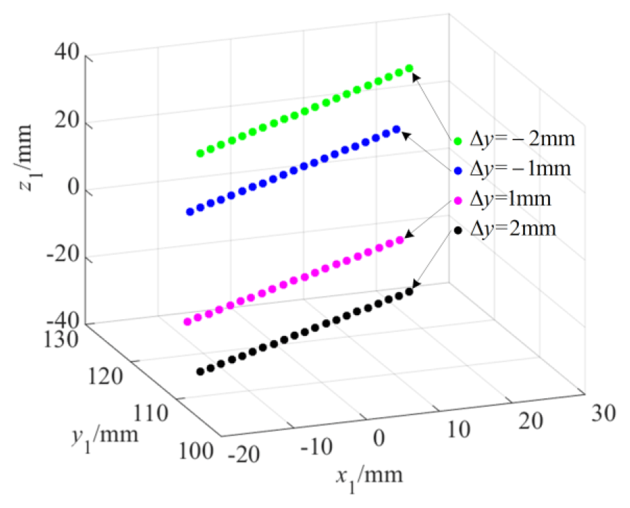
Figure 19 shows the tooth surface contact position when there is a translation error Δy along the y axis, and Fig. 20 shows the actual tooth surface contact trace with the translation error Δy along the y axis. Observing Fig. 19, the position of the tooth surface contact point deviates from the middle section as the translation error Δy increases, and its contact form will evolve into edge contact at one side of the tooth width within the range of the finite tooth width. The reason for this is that the translation error Δy causes tooth surface translation. When there is an error in the positive direction of the y axis, the tooth thickness in the negative direction of the tooth width increases, and the contact point moves towards the negative direction of the tooth width. Conversely, when there is an error in the negative direction of the y axis, the tooth thickness in the positive direction of the tooth width increases, and the contact point moves towards the positive direction of the tooth width. Moreover, the larger the translation error Δy is, the greater the increase in tooth thickness is, and the farther the deviation of the contact point position is. At the same time, due to the change in the contact position, the meshing trajectory of the gear pair changes, and the length of the actual meshing line also changes. It can be seen that the farther the deviation position is, the shorter the actual meshing line is.
As for the translation error Δx along the x axis, this has no impact on the 3D model of the VH-CATT cylindrical gear. That is, theoretically, the translation error Δx also has no impact on the tooth surface contact trace, and so it will not be discussed in detail. As for the translation error Δz along the z axis, the translation error Δz along the z axis is actually the positive and negative modification of the VH-CATT cylindrical gear. Its influence on the gear contact position and the length of the actual meshing line is similar to that of the rotational angle error β around the y axis, and so it also will not be discussed in this section.
Based on the LTCA model, the tooth surface load distribution, the maximum tooth surface load, the LTE, and the load distribution coefficient have been calculated. Figure 21 shows an example of the load distribution on the tooth surface, where Fig. 21a is the tooth surface load distribution of the ideal gear pair, and Fig. 21b is the tooth surface load distribution of the gear pair with the translation error =Δy. Observing Fig. 21, the load distribution on the tooth surface of an ideal gear pair is in the middle section of the tooth width. For a gear pair with a translation error Δy, the tooth surface load deviates from the middle section of the VH-CATT cylindrical gear. The calculation result is consistent with the research conclusion regarding the tooth surface contact trace of the VH-CATT cylindrical gear pair with a translation error Δy; the research on the load distribution law of the tooth surface caused by the cutter errors was completed in the early stage, and the details can be found in Ma et al. (2023b).
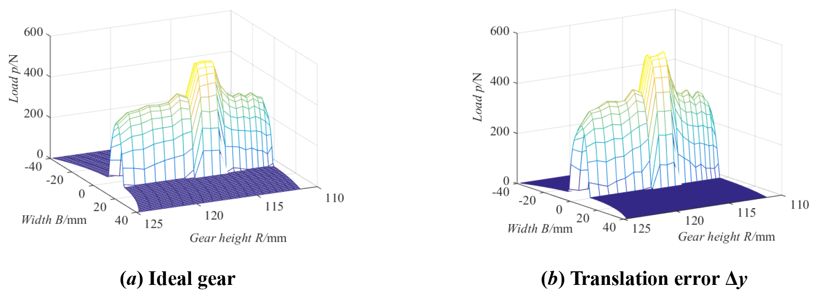
Figure 22 shows the influence of cutter errors on the tooth surface maximum load. Observing Fig. 22, the maximum load of the tooth surface decreases as a whole when there is a tooth line radius error ΔRT; the reason for this is that the contact area of the tooth surface increases. The maximum load of the tooth surface decreases in the single-tooth meshing area when there is a rotational angle error γ. The maximum load of the tooth surface increases in the single-tooth meshing area during the meshing-in process and decreases in the single-tooth meshing area during the meshing-out process when there is a pressure angle error Δα. The maximum load of the tooth surface increases slightly as a whole when there is a translation error Δz. The translation error Δy has little influence on the maximum load of the tooth surface.
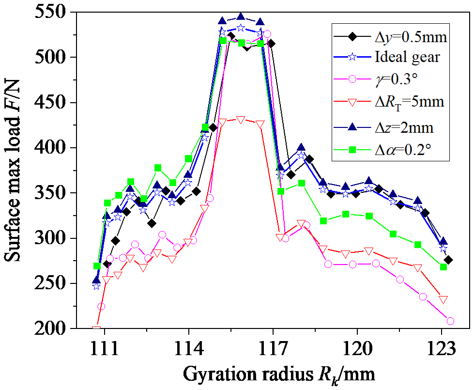
Figure 23 shows the influence of cutter errors on the load distribution coefficients. Observing Fig. 23, the cutter errors mainly affect the load distribution coefficient of the single-tooth meshing area. The load distribution coefficient decreases in the single-tooth meshing area, and the double-tooth meshing area decreases when there is a rotational angle error γ or translation error Δy. The load distribution coefficient increases in the meshing-in single-tooth meshing area and decreases in the meshing-out single-tooth meshing area when there is a pressure angle error Δα. The translation error Δz and tooth line radius error ΔRT have little influence on the load distribution coefficient.
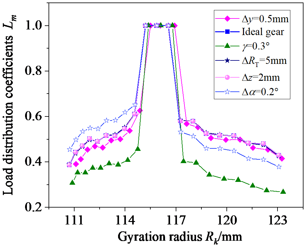
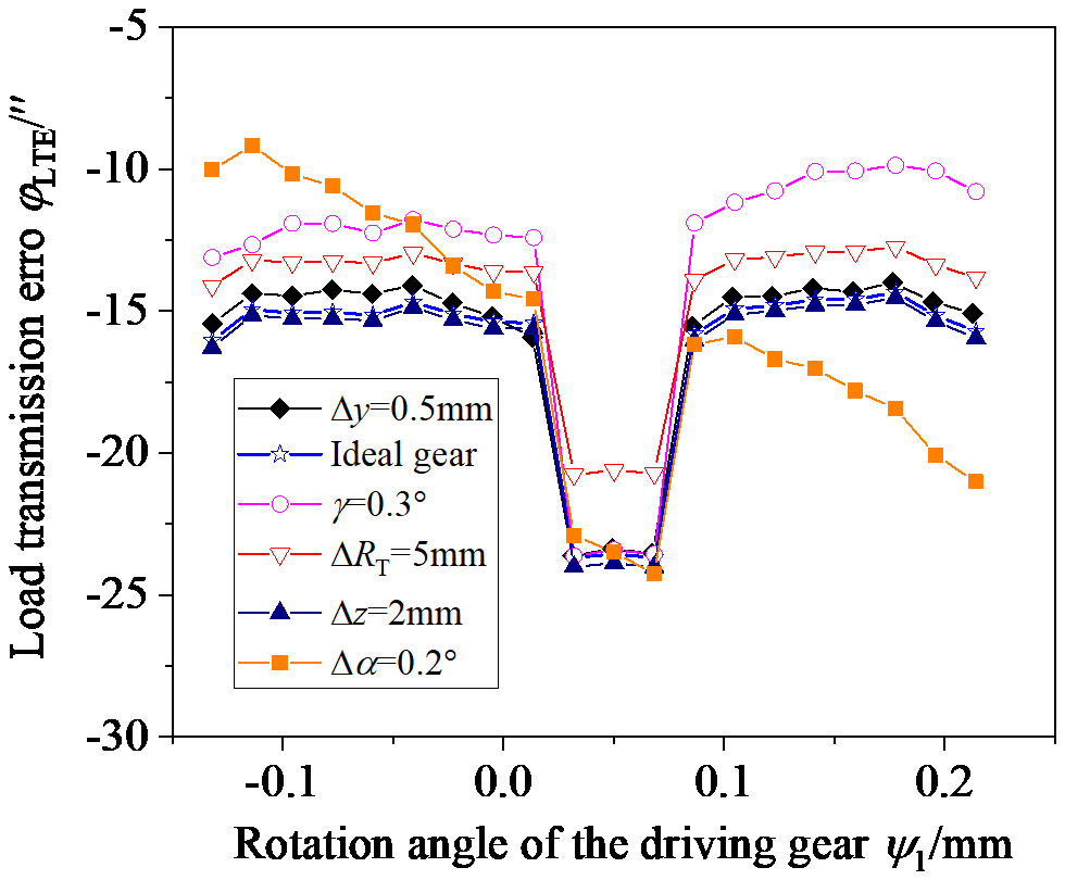
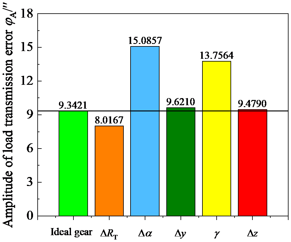
Figure 24 shows the influence of cutter errors on the LTE, and Fig. 25 shows the amplitude of the LTE. Observing Fig. 24, the cutter errors mainly affect the LTE of the single-tooth meshing area, except for the tooth line radius error ΔRT. In the single-tooth meshing area during the meshing-in process, LTE increases when there is a rotational angle error γ, a translation error Δy, a tooth line radius error ΔRT, and a pressure angle error Δα. LTE decreases slightly when there is a translation error Δz. In the single-tooth meshing area during the meshing-out process, LTE increases when there is a rotational angle error γ, a translation error Δy, and a tooth line radius error ΔRT. LTE decreases slightly when there is a translation error Δz and a pressure angle error Δα. However, observing Fig. 25, except for the tooth line radius error ΔRT, all cutter errors make the amplitude of the LTE increase, especially the rotational angle error γ and the pressure angle error Δα. Therefore, research shows that reasonably changing the tooth line radius can effectively reduce the noise of the VH-CATT cylindrical gear transmission system, while other cutter errors will increase the vibration of the VH-CATT cylindrical gear transmission system.
This paper discusses the meshing characteristics of a VH-CATT cylindrical gear with cutter errors. Firstly, a coordinate system for tooth surface formation with cutter errors is established, and the tooth surface equation with cutter errors is derived. Next, a TCA model and an LTCA model of the VH-CATT cylindrical gear pair are established, and the equation of the tooth surface contact ellipse and the formulas of the main curvature direction angles are derived. Then, the influences of the cutter errors on the contact ellipses, the tooth surface contact trace, and the loaded contact characteristics are analyzed. The main conclusions can be expressed as follows:
- 1.
The contact ellipse's major axis increases with an increase in ΔRT, but ΔRT has no influence on the contact ellipse's minor axis. The contact ellipse's major axis decreases with an increase in Δα when Δα is less than zero and increases when Δα is greater than zero. The contact ellipse's minor axis has the same variation law for Δα. The contact ellipse's major axis increases with an increase in γ in the area close to the tooth root and decreases in the area close to the tooth top, and γ has little influence on the contact ellipse's minor axis. The contact ellipse's major axis increases with an increase in β when β is less than zero and decreases when β is greater than zero, and the contact ellipse's minor axis has the same variation law for β. The contact ellipse's major axis decreases with an increase in Δy, and the variation of the contact ellipse's minor axis is the opposite of this. The contact ellipse's major axis increases with an increase in Δz when Δz is less than zero and decreases when Δz is greater than zero. Δz has no influence on the contact ellipse's minor axis. Δx also has no impact on the contact ellipses.
- 2.
ΔRT has no influence on the contact position within a certain range, but the contact form evolves from point contact to bridge contact when ΔRT is too large. Δα also has no influence on the contact position, but the actual meshing line increases or decreases. γ and Δy make the contact position deviate from the middle section. Δy has a relatively large impact on the actual meshing line. Δx has no influence on the contact position and the actual meshing line, the rotation angle error β does not change the contact position, and the influence of Δz is similar to this.
- 3.
ΔRT makes the maximum load of the tooth surface decrease, γ makes the maximum load of the tooth surface in the single-tooth meshing area decrease, and Δα makes the maximum load of the tooth surface in the meshing-in single-tooth meshing area increase; it is the opposite in the meshing-out single-tooth meshing area, whereby Δz makes the maximum load of the tooth surface increase slightly, and Δy has a small influence on the maximum load of the tooth surface. The tooth-surface-forming errors mainly affect the load distribution coefficient of the single-tooth meshing area.
- 4.
The cutter errors mainly affect the LTE of the single-tooth meshing area, but except for the tooth line radius error ΔRT. In the meshing-in single-tooth meshing area, the LTE increases when there are γ, Δy, ΔRT, and Δα values. The LTE decreases slightly when there is a Δz value. In the meshing-out single-tooth meshing area, the LTE increases when there are γ, Δy, and ΔRT values. The LTE decreases slightly when there are Δz and Δα values. Except for the tooth line radius error ΔRT, all cutter errors make the amplitude of the LTE increase.
All the code and data used in this paper can be obtained upon request to the corresponding author.
DM conceived the presented idea. DM and JL established an overall paper research framework and the model. DM conducted data calculation for the overall paper. ZZ participated in the revision of the paper. All of the authors discussed the results and contributed to the final paper.
The contact author has declared that none of the authors has any competing interests.
Publisher’s note: Copernicus Publications remains neutral with regard to jurisdictional claims made in the text, published maps, institutional affiliations, or any other geographical representation in this paper. While Copernicus Publications makes every effort to include appropriate place names, the final responsibility lies with the authors.
The authors would like to thank the anonymous reviewers for their valuable comments and suggestions that enabled us to revise the paper.
This work has been supported by the Zunyi Normal University Doctor Fund (grant no. Zunshi BS [2024] 03Hao) and the Zunyi Science and Technology Plan Project (grant nos. Zunshikehe HZ Zi [2024] 139Hao and Zunshikehe HZ Zi [2023] 152Hao).
This paper was edited by Daniel Condurache and reviewed by two anonymous referees.
Dongu, I., Woo, J., Hyunggon, L., You, J., Hyunjoon, S., Minwook, L., and Young, J.: Analysis of gear transmission error in helical gear using enhanced tooth contact analysis model considering measured tooth profile errors, Sci. Rep., 15, 5981, https://doi.org/10.1038/s41598-025-90010-6, 2025.
Dai, Z., Li, T., Zhang, Y., Zhou, J., and Zhang, R.: A model construction and measurement method for tooth surface deviation of spiral bevel gear-based a on one-dimensional probe, Meas. Sci. Technol., 34, 045001, https://doi.org/10.1088/1361-6501/acabdc, 2023.
Dongu, I., Woo-Jin, C., Hyunggon, L., You-Jin, L., Hyunjoon, S., Minwook, L., and Young-Jun, P.: Analysis of gear transmission error in helical gear using enhanced tooth contact analysis model considering measured tooth profile errors, Sci. Rep., 15, 5981, https://doi.org/10.1038/s41598-025-90010-6, 2025.
Ke, T., Ding, H., Geng, M., and Gong, C.: Automatic configuration analysis method of planetary gear automatic transmission, P. I. Mech. Eng. D-J. Aut., 239, 886–904, https://doi.org/10.1177/09544070231207163, 2025.
Li, F., Wang, S., Chen, P., Li, Z., Li, L., and Zou, H.: Optimization of high-efficiency tooth surface accuracy of spiral bevel gears considering machine-tool motion errors, P. I. Mech. Eng. D-E. Pro., 237, 1394–1406, https://doi.org/10.177/9544089221113639, 2023b.
Li, G., Wu, C., Xu, K., Ran, Q., and Cao, B.: Pivotal errors identification of the face gear worm grinding machine tool with a piecewise sensitivity analysis, Mech. Mach. Theory, 181, 105206, https://doi.org/10.1016/j.mechmachtheory.2022.105206, 2023c.
Li, M., Wang, S., Ma, C., and Xia, C.: Identification of key errors for large-sized gear hobbing machines based on tooth surface posture-geometric error model, Chin. Mech. Eng., 34, 533–542, 2023a (in Chinese).
Liang, S., Luo, P., Hou, L., Duan, Y., Zhang, Q., and Zhang, H.: Research on processing error of special machine tool for VH-CATT cylindrical gear, Machines, 10, 679–679, https://doi.org/10.3390/machines10080679, 2022.
Liang, S., Wu, Y., Hou, L., Dong, L., Fan, Q., and Zhang, H.: Research on influence mechanism of geometric error sources on tooth surface error of VH-CATT gear special machine tool, Int. J. Adv. Manuf. Tech., 128, 5529–5546, https://doi.org/10.1007/s00170-023-12001-z, 2023.
Litvin, F. L.: Gear geometry and applied theory, Shanghai Science and Technology Press, China Shanghai, ISBN 9787532394203, 2008.
Liu, Y. and Ma, D.: Surface modification and tooth contact analysis of variable hyperbolic circular-arc-tooth-trace cylindrical gears, Mech. Sci., 13, 909–920, https://doi.org/10.5194/ms-13-909-2022, 2022.
Ma, D., Ye, Z., and Yang, H.: Tooth surface reconstruction and tooth profile geometric analysis of circular arc tooth trace cylindrical gears, T. Famena, 43, 29–44, https://doi.org/10.21278/TOF.43103, 2019.
Ma, D., Liu, Y., and Ye, Z.: Analysis of the tooth surface contact area of a circular arc tooth trace cylindrical gear under load, T. Famena, 45, 79–94, https://doi.org/10.21278/TOF.451018220, 2021.
Ma, D., Liu, Y., and Ye, Z.: Modification design and load tooth contact analysis of a cylindrical gear with variable hyperbolic circular arc tooth trace, J. Vib. Shock, 42, 170–179, 2023a (in Chinese).
Ma, D., Liu, Y., Ye, Z., Li, D., and Wu, Y.: Influence of cutter errors on forming accurate variable hyperbolic circular arc tooth trace cylindrical gears, T. Famena, 47, 13–31, https://doi.org/10.21278/TOF.474044222, 2023b.
Ma, D., Jiang, B., Bao, L., Ye, Z., and Liu, Y.: Study on the contact performance of the variable hyperbolic circular arc tooth trace cylindrical gear with installation errors, Mech. Sci., 15, 353–366, https://doi.org/10.5194/ms-15-353-2024, 2024a.
Ma, D., Jiang, B., Ye, Z., and Liu, Y.: Meshing stiffness characteristics of modified variable hyperbolic circular-arc-tooth-trace cylindrical gears, Mech. Sci., 15, 395–405, https://doi.org/10.5194/ms-15-395-2024, 2024b.
Ren, L.: Research on geometric error mapping and compensation of large-scale CNC gear hobbing machine tools, Chongqing University, Chongqing, 2019 (in Chinese).
Rituraj, F., Vacca, A., and Morselli, M.: Modeling of manufacturing errors in external gear machines and experimental validation, Mech. Mach. Theory, 140, 457-478, https://doi.org/10.1016/j.mechmachtheory.2019.06.016, 2019.
Song, C., Xia, M., Liu, S., and Liang, C.: Influences of machine-tool setting errors on mesh behavior for small-module spiral bevel gear, J. Mech. Sci. Technol., 36, 4523–4533, https://doi.org/10.1007/s12206-022-0816-0, 2022.
Sun, S.: Research on multi-source error modeling and compensation method of CNC gear hobbing, Chongqing University, Chongqing, 2018 (in Chinese).
Tang, Z., Zhou, Y., Wang, S., Zhu, J., and Tang, J.: An innovative geometric error compensation of the multi-axis CNC machine tools with non-rotary cutters to the accurate worm grinding of spur face gears, Mech. Mach. Theory, 169, 104664, https://doi.org/10.1016/j.mechmachtheory.2021.104664, 2022.
Tian, F., Hou, L., Xie, C., and Zhao, F.: Kinematic chain design and error analysis of machine tool for cylindrical gear with arcuate tooth traces, Mach. Des. Manuf., 77–80, 2019 (in Chinese).
Wang, P., Wang, C., Wen, B., Ma, H., and Yang, Y.: Vibration features and sidebands investigation of a planetary gear transmission system under misaligned bearing and damaged cage, Measurement, 248, 116864, https://doi.org/10.1016/j.measurement.2025.116864, 2025.
Wei, Y., Yang, D., Guo, R., Liu, Y., Luo, L., and Li Z.: Wear characteristics analysis of variable hyperbolic circular-arc-tooth-trace cylindrical gear transmission considering assembly error theory, P. I. Mech. Eng. J-J. Eng., 238, 399-413, https://doi.org/10.1177/13506501231218493, 2024a.
Wei, Y., Wang, Y., Li, Z., Jiang, B., Guo, R., and Zhang, J.: Geometric contact characteristics of variable hyperbolic circu-lar-arc-tooth-trace cylindrical gear under different machine tool errors and sensitivity analysis for impact factors, J. Strain Anal. Eng., 59, 269–280, https://doi.org/10.1177/03093247241232865, 2024b.
Wu, Y., Hou, L., Ma, D., Wei, Y., and Luo, L.: Milling machine error modelling and analysis in the machining of circular-arc-tooth-trace cylindrical gears, T. Famena, 44, 13–29, https://doi.org/10.21278/TOF.444009419, 2020a.
Wu, Y., Hou, L., Luo, L., Ma, D., Wei, Y., and Yi, Z.: Research on the effect law of machine tool errors on tooth surface errors of Curvilinear Gear, J. Mech. Eng., 56, 100–109, 2020b (in Chinese).
Wu, Y., Luo, P., Bai, Q., Liang, S., Fan, Q., and Hou, L.: Modelling and analyzing of loaded meshing characteristics of cylindrical gear transmission with curvilinear-shaped teeth, Meccanica, 58, 1555–1580, https://doi.org/10.1007/s11012-023-01690-1, 2023.
Yang, J., Si, L., Li, J., Xin, W., Zhao, B., and Wei, B.: Sensitivity analysis and compensation for tooth surface deviation of spiral bevel gear machine tool, Sci. Rep., 14, 22736, https://doi.org/10.1038/s41598-024-73509-2, 2024.
Yang, X., Song, C., Zhu, C., and Liu, S.: Tooth surface deviation and mesh analysis of beveloid gears with parallel axis considering machine tool adjustment errors, J. Adv. Mech. Des. Syst., 12, JAMDSM0082, https://doi.org/10.1299/jamdsm.2018jamdsm0082, 2018.
Yang, Y., Huang, X., Yu, C., Ding, S., and Lin, X.: Influence and correction for gear accuracy with geometric location errors in power skiving, Comp. Integr. Manuf. Syst., 25, 1101–1111, 2019 (in Chinese).
Yang, Y., Mao, S., Wang, D., Cao, W., Li, X., and Liu, C.: Completing process method for spiral bevel gear and sensitivity analysis of machine tool motion error, J. Zhejiang Univ. (Eng. Sci.), 56, 879–889, 2022 (in Chinese).
Yao, J. and Hong, R.: Modeling of the mapping relationship between machine tool errors and free-form milling machining errors, J. Mech. Trans., 46, 42–48, 2022 (in Chinese).
- Abstract
- Introduction
- Tooth surface mathematical model of the VH-CATT cylindrical gear with cutter errors
- TCA model, LTCA model, and contact ellipses
- Influence of the cutter errors on the contact ellipses
- Influence of the cutter errors on the tooth surface contact trace
- Influence of the cutter errors on the loaded contact characteristics
- Conclusion
- Code and data availability
- Author contributions
- Competing interests
- Disclaimer
- Acknowledgements
- Financial support
- Review statement
- References