the Creative Commons Attribution 4.0 License.
the Creative Commons Attribution 4.0 License.
 | 21 Jul 2025
Conversion of four-stroke engines to six-stroke engines using epicyclic gearing in camshaft modification
Muhammed Akar
In this study, a compact, single-cylinder, spark-ignition, four-stroke engine commonly used in power generators is converted into a six-stroke engine. This conversion employed the free-stroke Kelem model, one of the six-stroke engine approaches described in the literature, which required modifications only to the camshaft. Without modification to the original crankshaft gear, a fixed-ratio epicyclic gear was applied to the camshaft gear to achieve the necessary speed ratio between the crankshaft and camshaft. Following the verification of the engine's original camshaft dimensions, new cam profiles were designed using a two-circular-arc cam profile. The cam lobes and cam gear were manufactured and assembled separately. During the experiments, a resistive load bank with a capacity ranging from 400 to 4000 W was employed to load the power generator and assess the engine's performance parameters. Fuel consumption, oil temperature, and exhaust gas temperature were measured, from which thermal efficiency, specific fuel consumption, and fuel consumption per cycle were calculated. The results showed that oil temperature decreased by 3.1 %, exhaust gas temperature decreased by 15.4 %, and thermal efficiency increased by 15.8 %. However, fuel consumption per cycle in the six-stroke engine increased by 29.9 %, indicating a higher engine load demand to achieve the desired power output. This study uses the original dimensions and characteristics of the test engine as a reference. No further modifications were made apart from the camshaft adjustment. The experimental findings demonstrate that four-stroke engines can be successfully converted into six-stroke engines, achieving improved fuel economy at the expense of reduced power output. The implementation of an epicyclic gear system into the camshaft gear without any modification to the crankshaft gear, along with the experimental validation of the model's usability, distinguishes this study from the existing literature.
- Article
(6626 KB) - Full-text XML
- BibTeX
- EndNote


Internal combustion engines have been the primary energy conversion system for both mobile and stationary applications since the 1890s owing to their high-power density, energy efficiency, reliability, and cost-effectiveness (Van Basshuysen and Schäfer, 2016). With advancements in technology, internal combustion engines have been continuously improved to satisfy environmental, performance, and economic criteria. However, a key drawback of internal combustion engines that rely on fossil fuels is the pollutant emissions resulting from the combustion process. In response, both developed and developing countries have implemented stringent regulations to mitigate these emissions (Winkler et al., 2018; Uyumaz et al., 2024). A recent trend in the transportation industry is the shift from internal combustion engine vehicles to battery electric vehicles, which are regarded as a potential solution to critical issues such as climate change and the energy crisis. Unlike conventional internal combustion engine vehicles, battery electric vehicles utilize electrical energy as fuel, offering significant advantages. While it is estimated that the total life cycle carbon footprint could be reduced by up to 40 % with the adoption of electric vehicles over internal combustion engine vehicles, several challenges remain. These include battery production, electricity generation, charging infrastructure, energy transfer time, range limitations, battery disposal, and vehicle safety, all of which continue to be topics of active debate (Fenfeo Automation Private Limited, 2024; Desreveaux et al., 2023; Farzaneh and Jung, 2023).
According to the Internal Combustion Engine Market Size, Share, and Trends Analysis Report published in November 2023, global demand for internal combustion engines was approximately 182 000 units in 2022 and is projected to grow at a compound annual growth rate of 9.2 % through 2030 (Grand View Research, 2024). Despite a decline in the popularity of internal combustion engines within the transportation sector, demand for these engines remains strong, primarily driven by the agriculture, construction, mining, and power generation industries. Hybrid electric vehicles, which integrate an internal combustion engine with an electric motor, constitute a notable improvement in the transportation industry. These vehicles inherently produce fewer emissions, have a lower carbon footprint, and offer reduced operational costs compared to conventional internal combustion engine vehicles. Additionally, hybrid electric vehicles provide superior fuel efficiency and lower operating costs (Verma et al., 2021; Zhang et al., 2020).
In hybrid electric vehicles, advanced engines using Atkinson cycle technology are employed to enhance fuel economy and reduce pollutant emissions (Asef et al., 2024). Atkinson cycle engines achieve higher energy efficiency by extending the expansion stroke relative to the compression stroke. Although they are structurally similar to conventional Otto cycle engines, Atkinson cycle engines feature modified valve timing that allows for a longer power stroke than the compression stroke. This extended power stroke improves energy efficiency but results in reduced power output (Feng et al., 2016; Özdemir et al., 2022). Consequently, the displacement of Atkinson cycle internal combustion engines used in hybrid electric vehicles is generally larger than that of internal combustion engines in conventional vehicles. Six-stroke engines are primarily designed to improve fuel economy (Yang et al., 2023; Arabacı et al., 2015; Conklin and Szybist, 2010). Given their potential benefits, six-stroke engines are anticipated to emerge as a viable alternative to the Atkinson cycle engines currently used in hybrid electric vehicles.
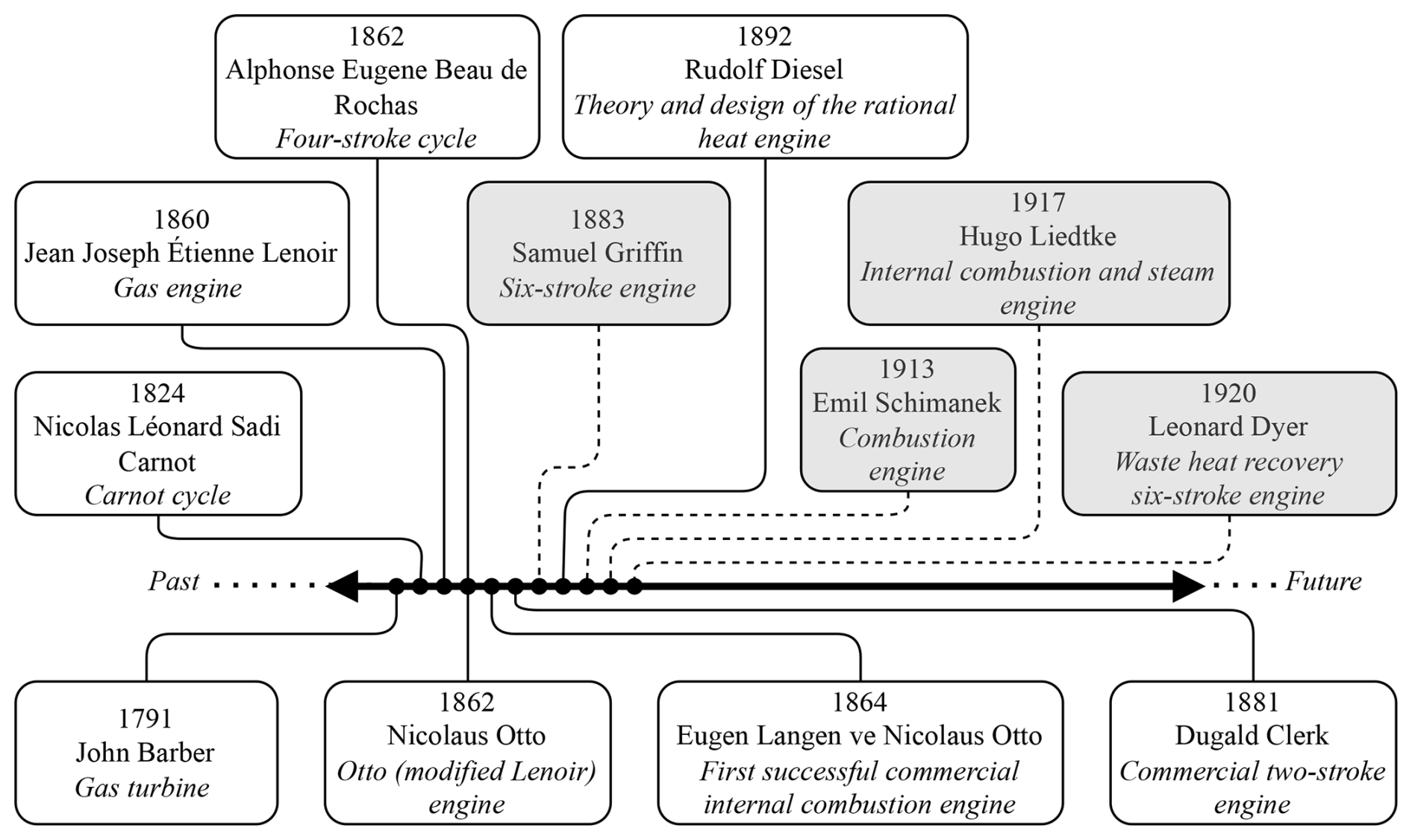
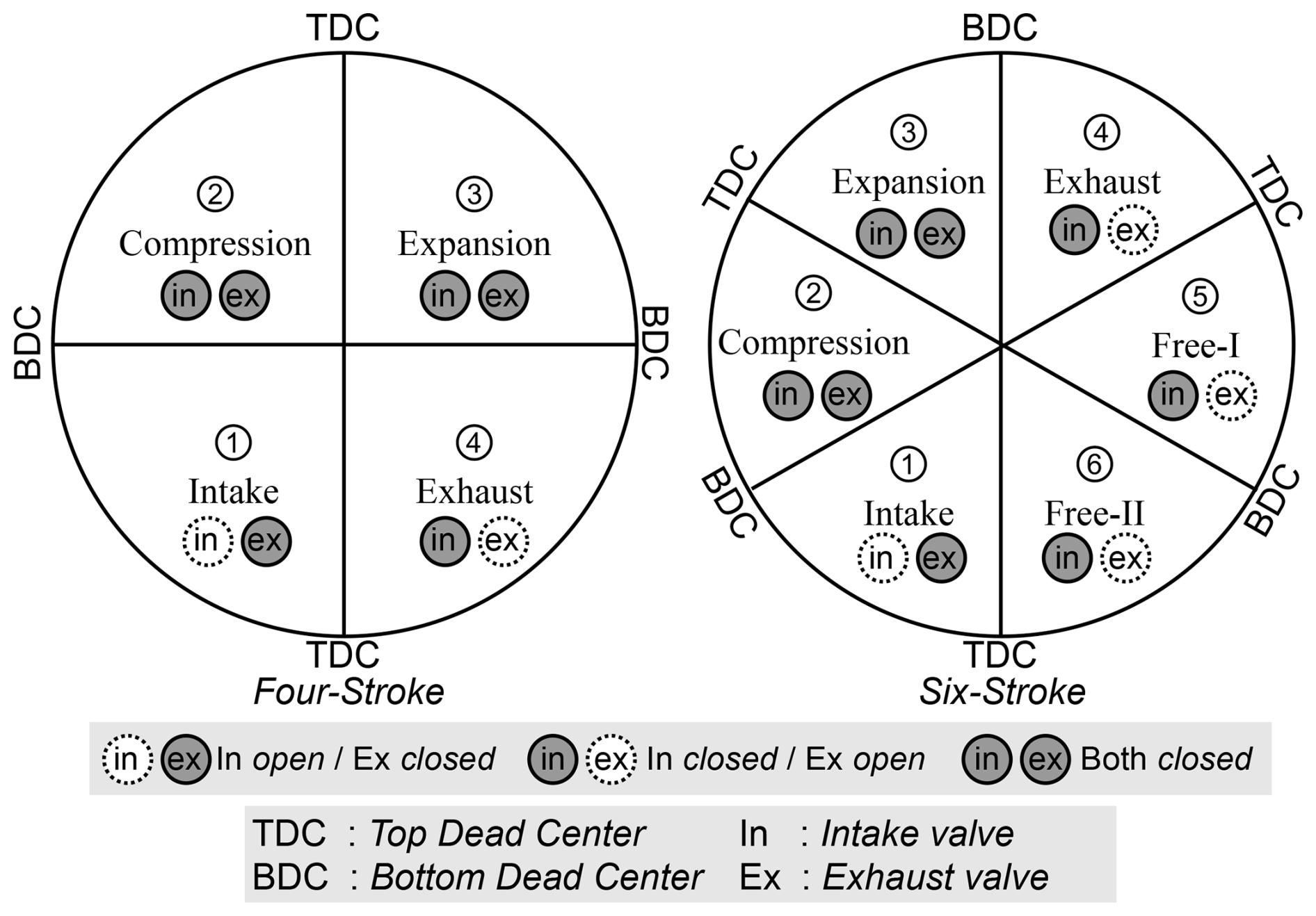
Six-stroke engines, classified as internal combustion engines, serve as an alternative to the two-stroke and four-stroke engines commonly used today. Structurally, they closely resemble four-stroke engines. The primary objective of six-stroke engines is to enhance efficiency and fuel economy. Broadly, six-stroke engines are categorized into two main approaches: the single-piston approach and the opposed-piston approach (Arabacı et al., 2015; Arabacı and Içingür, 2016). As this study focuses on the single-piston approach, the literature review is limited to six-stroke engines employing this design. In the single-piston approach, two additional strokes are incorporated into the conventional four-stroke cycle. A historical analysis of engine technology reveals that six-stroke engines are nearly as old as many of the engine technologies in use today (Fig. 1).
According to the historical timeline of engine technology, the principle of the six-stroke cycle was initially introduced by Griffin in 1889 (Griffin, 1889; Gabora, 2013; Arabacı and İçingür, 2016). In 1913, Schimanek aimed to enhance the power stroke's effect by increasing the volumetric efficiency of the internal combustion engine. To achieve this, they introduced a novel six-stroke cycle, which in turn inspired further research in the field. In their study, the charge entering the cylinder was compressed, routed to a pre-chamber, and then pressurized back into the cylinder (Schimanek, 1913). In 1917, Liedtke proposed an engine concept that combined features of both internal combustion and steam power. Their study suggested that the waste heat in the cylinder, specifically from the inner wall and piston surface, generated during combustion and not directly converted into useful power, could be utilized to create an additional power cycle using steam. For this cycle to function, the crankshaft needed to complete three full revolutions per cycle (Liedtke, 1917). Leonard Dyer significantly advanced the concept of six-stroke engines in 1920. Their study identified three main objectives: increasing thermal efficiency by recovering heat produced during gas expansion, optimizing the gas exchange process and alleviating the burden on the cooling system (Dyer, 1920). The single-piston six-stroke engine model referenced in various studies is based on Dyer's patent. While structurally similar to four-stroke engines, this six-stroke concept differs primarily in valve timing and the use of a water injection system designed to recover waste heat. Functionally, it operates as a combination of an internal combustion engine and a steam engine, incorporating two additional strokes beyond the conventional four-stroke cycle. Following Dyer's study, numerous patents related to six-stroke engine concepts have been developed. One of the most significant contributions in this field is the research conducted by Kelem and Kelem (hereafter referred to as Kelem). Unlike Dyer's approach, which focused on waste heat recovery through water injection, Kelem's research aimed to reduce residual gas concentration within the cylinder and cool the cylinder interior by implementing two additional free strokes. This approach not only reduced the demand for engine cooling but also improved engine performance by increasing volumetric efficiency (Kelem and Kelem, 2010).
The fundamental difference between the studies of Dyer and Kelem resides in their valve timing strategy. In both concepts, the cycle is completed in three crankshaft revolutions. Consequently, while the angular velocity ratio between the crankshaft and the camshaft is 3 : 1, the engine's operating characteristics can be adjusted through an appropriate cam profile. This section compiles significant studies conducted using the engine concepts of Dyer and Kelem. Both Dyer's and Kelem's engine concepts are six-stroke engines employing a single-piston approach. Due to the structural similarities between six-stroke and four-stroke engines, the transition from four-stroke to six-stroke engines has consistently attracted interest (Arabacı et al., 2015; Arabacı and İçingür, 2016; Conklin and Szybist, 2010; Gupta et al., 2018; Rajput et al., 2019, 2020, 2021). Six-stroke engines are developed by modifying the valve mechanisms of four-stroke engines, thereby extending the cycle. The primary objective of this conversion is to increase thermal efficiency (Arabacı et al., 2015; Arabacı and İçingür, 2016; Conklin and Szybist, 2010).
Theoretical studies have shown that thermal efficiency can significantly improve, particularly through exhaust heat recovery via direct water injection (Conklin and Szybist, 2010; Chen et al., 2015). The thermal efficiency in this context varies depending on the water injection parameters. The application of free strokes, as seen in the Kelem model, also theoretically enhances thermal efficiency in place of exhaust heat recovery. This suggests that six-stroke engines are well suited for hybrid electric vehicles, where maximizing thermal efficiency outweighs power density requirements (Arabacı, 2021). The conversion of gasoline-powered four-stroke engines to six-stroke engines through water injection and exhaust heat recovery has been reported to yield an approximate 9 % increase in thermal efficiency under optimal water injection parameters. Additionally, the impact of water injection and exhaust heat recovery on engine performance has been estimated to be approximately 10 % (Arabacı et al., 2015). However, while thermal efficiency increases in six-stroke engines, power output is typically reduced due to the longer cycle duration. Alongside this transition, the engine cooling load also decreases significantly. The cylinder wall and exhaust gas temperatures in six-stroke engines are lower compared to those in four-stroke engines, which can be exploited as an advantage for enhancing engine performance.
By employing alternative crank mechanisms, the power stroke can be mechanically extended (Arabacı and Kılıç, 2018). Alternative fuels such as acetylene, ethanol, and methanol can be utilized (Gupta et al., 2018; Kanna and Pinky, 2020). Both Dyer and Kelem models continue to inspire theoretical and experimental studies on six-stroke engine conversions. Particularly for applications where fuel economy is a priority, six-stroke engine concepts remain a subject of ongoing development and research.
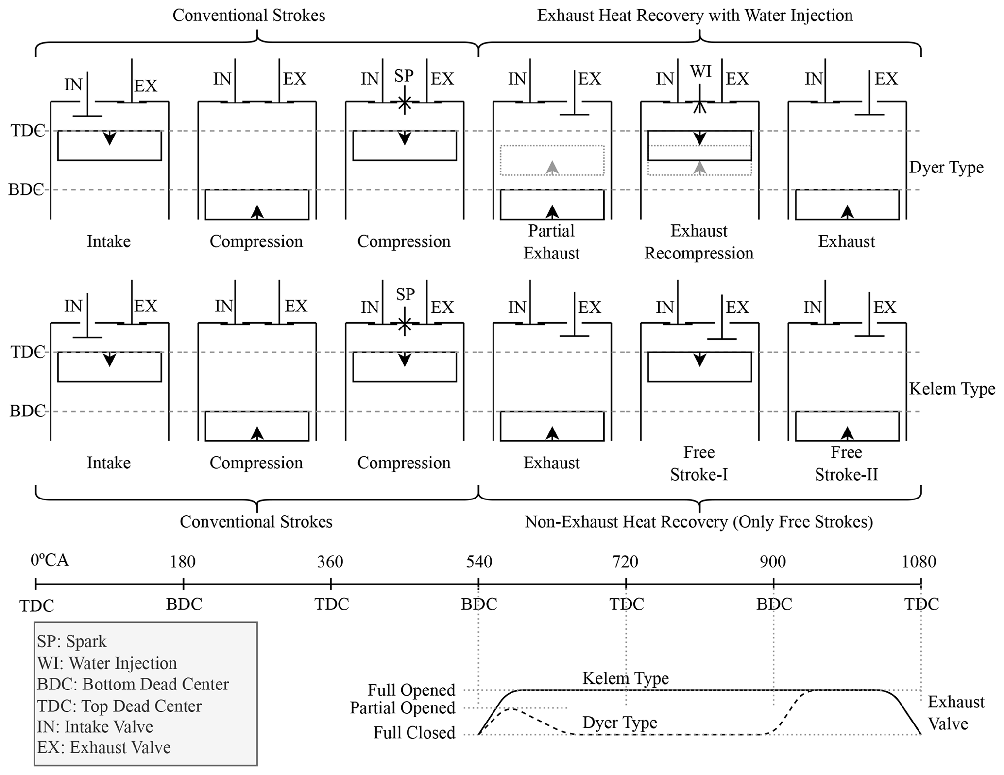
Based on the literature review, no experimental studies have been conducted on six-stroke engines using the Kelem model. However, for the implementation of exhaust heat recovery with water injection, an additional water injection control system must be developed. The six-stroke engine model proposed by Kelem is less efficient than Dyer's but offers a practical approach for converting four-stroke engines into six-stroke engines (Fig. 2). Additionally, the Kelem model may be further improved by adopting various gas exchange strategies (Arabacı, 2022).
In converting four-stroke engines to six-stroke engines, compact single-cylinder engines are commonly preferred. The primary modification in this process involves adjusting the crank-to-cam angular velocity ratio. Previous studies have shown that to alter this ratio from 2 : 1 to 3 : 1, the crank gear is downsized, and the cam gear is enlarged accordingly (Yang et al., 2023; Thatoi and Gaur, 2023; Gupta et al., 2018; Arabacı et al., 2015). While this conversion is considered practical, enlarging the camshaft is not always feasible, particularly in compact engine designs. Additionally, since the crankshaft–camshaft center distance cannot be altered, both cam and crank gear dimensions generally require modification.
As an alternative, using an epicyclic gear for the camshaft allows the crank-to-cam angular velocity ratio to be adjusted from 2 : 1 to 3 : 1 without altering the crank gear dimensions (Arabacı and İçingür, 2021). This enables the conversion of four-stroke engines into six-stroke engines by modifying only the camshaft architecture. According to the literature review, no experimental studies have investigated the application of epicyclic gearing on the camshaft. In this study, a compact four-stroke spark ignition engine from a power generator was converted into a six-stroke engine following the Kelem model. For the conversion, the cam gear was replaced by an epicyclic gear system, and the camshaft was redesigned as a multi-component assembly along with the cam lobes. The generator was subjected to electrical (resistive) loading, and performance data were recorded for both four-stroke and six-stroke engine configurations. The results were subsequently compared and analyzed (Yang et al., 2023; Thatoi and Gaur, 2023; Gupta et al., 2018; Arabacı et al., 2015).
Modern vehicles equipped with Atkinson cycle engines exhibit a higher geometric compression ratio compared to conventional engines. However, various valve timing strategies are employed to reduce the effective compression ratio, resulting in a high-efficiency engine with an extended expansion process. In the proposed approach of this study, only the camshaft and, consequently, the valve timing strategy are modified to achieve a high-efficiency engine comparable to an Atkinson cycle engine. In this respect, while an Atkinson cycle engine requires modifications to both the valve timing strategy and the engine's geometric design to accommodate a high compression ratio, the six-stroke engine concept achieves this efficiency-focused approach solely through the redesign of the camshaft. Due to this expected design advantage, it is claimed that the proposed six-stroke engine concept has the potential to be utilized in hybrid electric vehicles.
To facilitate the conversion of the four-stroke engine to a six-stroke engine, modifications to the cam gear and adaptations of the valve timing were introduced. These two fundamental changes to the camshaft are thoroughly discussed below. Subsequently, a new camshaft was fabricated in alignment with these modifications. During the production of the camshaft, the cam gear and the shaft incorporating the cam lobes were manufactured separately and subsequently joined using a screw connection. An experimental setup was established to evaluate the engine performance parameters.
2.1 Experimental setup
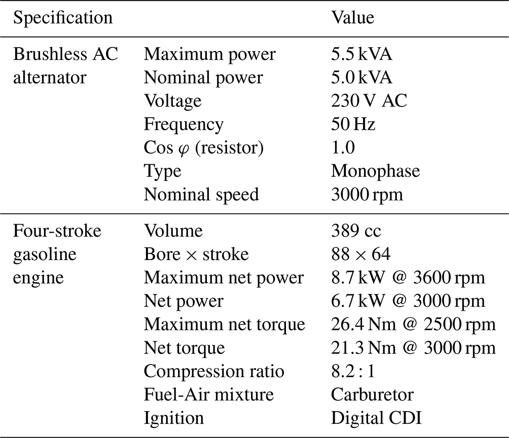
A portable gasoline-powered generator was used in the experiments. This power generator consists of an internal combustion engine coupled with a brushless AC alternator. In the setup, the alternator functioned as an engine dynamometer, allowing for constant-speed, variable-load tests. To adapt the engine for the experiments, several modifications were made to its internal components. The technical specifications of the power generator are provided in Table 1.
Table 1Technical specifications of the power generator (Honda Engines, 2024).
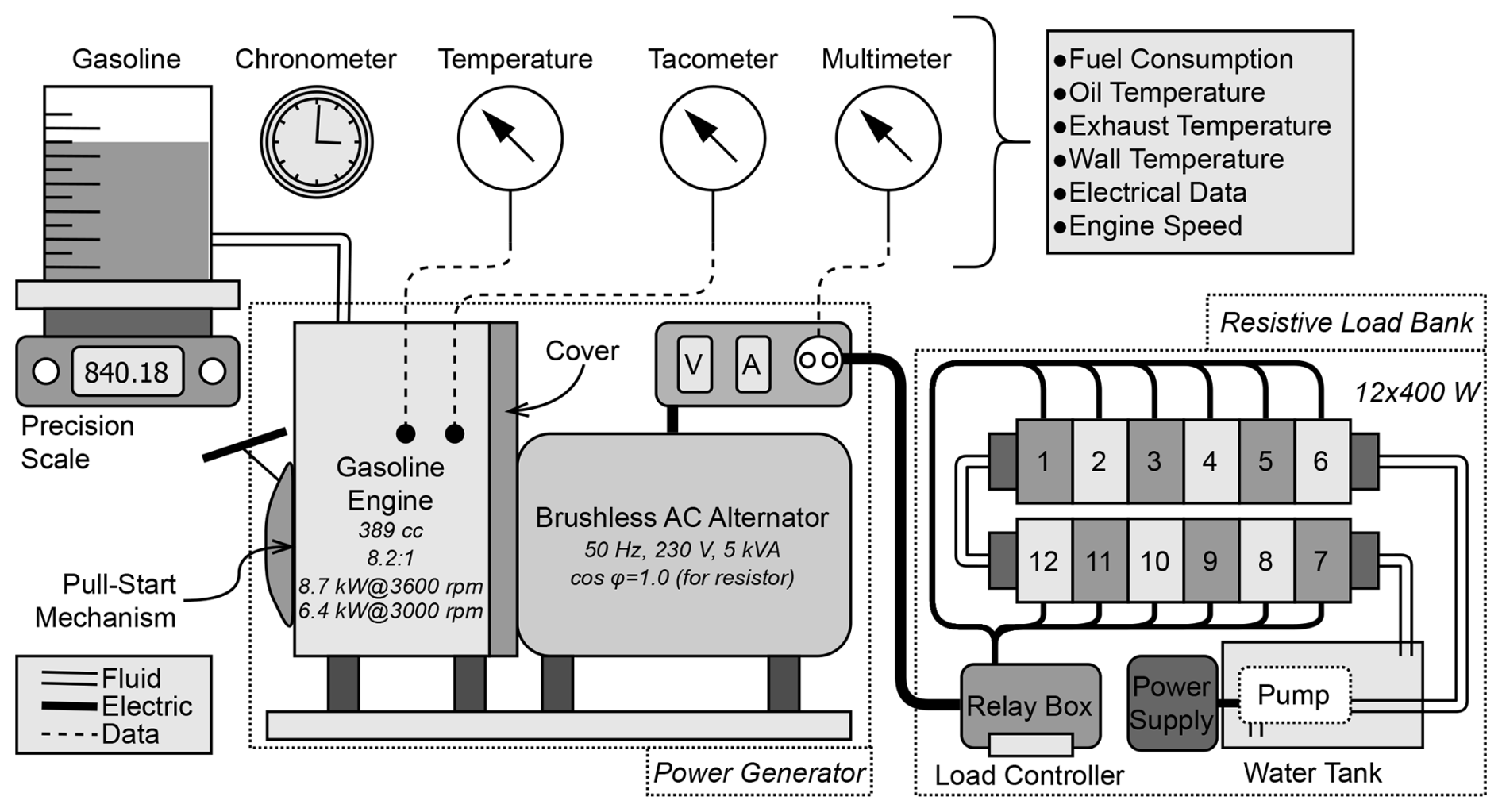
The experimental setup included a resistive load (Fig. 3). The resistors were mounted on aluminum pipes with an outer diameter of 50 mm. Water from a 100 L tank was circulated through the aluminum pipes using a pump, facilitating heat transfer from the resistors to the water. To achieve the desired electrical load, all resistors were controlled by a load controller implemented with a 16-channel relay module and a microcontroller (Atmega 32U4). During the experiments, all electrical data were measured with a multimeter. The engine speed was maintained at a constant 3000 rpm via a mechanical speed governor integrated into the internal combustion engine. This centrifugal governor operates within specified tolerances, which may result in deviations depending on the load conditions. To verify the engine speed, a non-contact tachometer (Uni-T 372; accuracy: ±0.04 %, precision: 1 rpm) was used. If significant deviations were detected, adjustments were made using the governor control arms. Temperature measurements for the cylinder wall, exhaust, and oil were conducted with K-type thermocouples (Uni-T UT325F; accuracy: ±0.2 % + 0.5 °C, precision: 0.1 °C). Fuel mass consumption was measured using a precision scale (Radwag WTC 2000; precision: 0.01 g, accuracy: ±0.03 g) and a digital stopwatch (Kalenji Onstart 110; precision: 0.01 s, accuracy: ±0.02 s). Additionally, a multimeter (HP 760C; voltage precision: 1 V, voltage accuracy: ±2.5 %, current precision: 0.01 A, current accuracy: ±2 %) was used to monitor the resistive load and collect electrical data.
Errors in the experiment can stem from factors such as observation, operating temperature, instrument types, calibration of measurement devices, and testing procedure. The accuracy of the experiment is quantified in terms of uncertainty. Total uncertainty is calculated as the square root of the sum of the squares of the uncertainties associated with each measurement device (Holman, 2021; Huang et al., 2015; Nayyar et al., 2017). Accordingly, the total uncertainty has been determined to be 3.22 %.
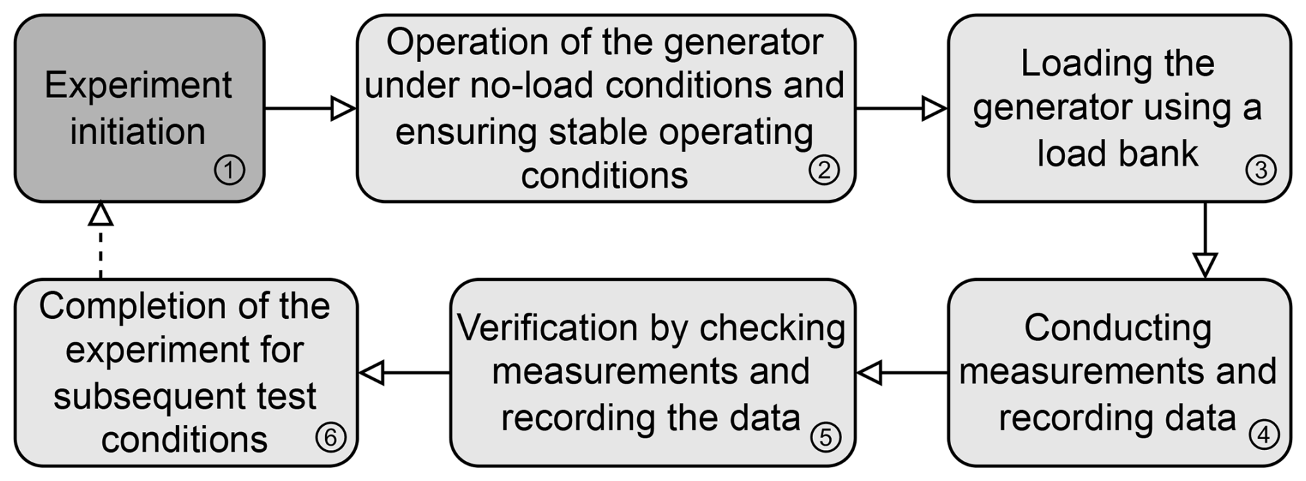
In all experiments, the procedure outlined in Fig. 4 was followed. Once the generator reached steady-state operating conditions, a load was applied using a resistive load bank. After applying the load, steady-state data were recorded. To verify the accuracy of the measurements, the generator was briefly operated without load, and the recorded data were checked. After all data were collected, the load was adjusted using the resistive load bank, and the next test conditions were initiated.
Since the engine used in the experimental study operates at a constant speed of 3000 rpm, a variable load test was conducted. During this test, a resistive power (PRES) was applied in 10 stages, ranging from 400 to 4000 W, with safety measures ensured throughout. One of the fundamental performance parameters, specific fuel consumption (sfc), is calculated as follows:
Here, (g h−1) represents the fuel consumption rate. A measurement period of 4 min was established to determine fuel consumption, during which the initial fuel mass (mi) and final fuel mass (mf) were recorded. Consequently, was calculated as follows:
The mechanical efficiency (ηm) between the internal combustion engine and the alternator in the generator is considered to be around 0.95. For resistive loads, cos φ is taken to be 1. Based on these assumptions, PICE can be calculated as follows:
Another fundamental performance parameter is brake thermal efficiency:
In this context, LHV refers to the lower heating value of the fuel, which is estimated to be about 44 000 J g−1 for gasoline. A key distinction between four-stroke and six-stroke engines is the number of cycles completed at a constant engine speed. Therefore, to evaluate and compare the performance of both cycles, fuel consumption per cycle (mg per cycle) is calculated as follows:
Here, n represents the engine speed (rpm) and c indicates the number of crankshaft revolutions required to complete one cycle. For four-stroke engines, c=2, whereas for six-stroke engines, c=3.
2.2 Modification of the cam gear to epicyclic gearing
Epicyclic gearing, also known as a planetary gear set, consists of three primary components: the sun gear, ring gear, and planet carrier. The terminology related to epicyclic gearing is illustrated in Fig. 5a. Figure 5b and c depict the complete schematic and gear set diagram of an epicyclic gearing, respectively, while Fig. 5d illustrates the speed relationships between the components.
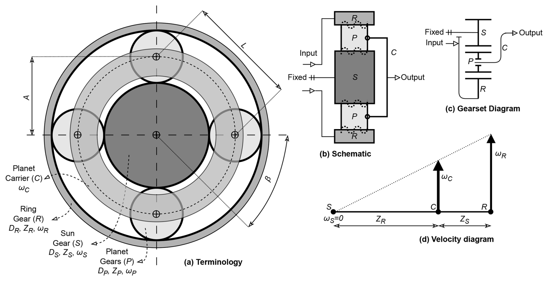
The planet carrier is not a gear but rather a structural support for the planet gears, which are mounted on it. The sun gear and ring gear rotate about fixed axes. The planet gears establish the motion relationship between the sun gear and the ring gear. A key limitation of epicyclic gearing concerns the number of teeth on the gears. When denoting the number of teeth for the sun gear, ring gear, and planet gear as ZS, ZR, and ZP, respectively, the following condition must hold:
Here, the number of planet gears, denoted as NP, is another critical parameter in the design of planetary gear systems. The following relationship is used to determine the optimal configuration of the planetary gear system:
When the center-to-center distance between the sun gear and the planetary gear is denoted as A, the distance between the two planetary gears is represented by L, and the gear module is designated as M, the following condition must be satisfied:
The equations above are essential for defining the dimensions of an epicyclic gearing. Unlike conventional gear systems, which typically have a single input-and-output shaft, epicyclic gearing consists of three interconnected components, each with distinct speeds and rotational directions. These components correspond to the sun gear shaft, ring gear shaft, and planet carrier shaft. Given the angular velocities of the sun gear, ring gear, and planet carrier are ωS, ωR, and ωC, respectively, the following relationship is obtained:
In this configuration, when any two of the three components serve as the input and output, the third component must remain “fixed”. In a conventional four-stroke engine, the camshaft gear drives the crankshaft gear with a gear ratio of GR=2 : 1 (Fig. 6a). However, in a six-stroke engine, when the camshaft gear drives the crankshaft gear, the gear ratio should be GR=3 : 1 (Fig. 6b). Maintaining a constant center-to-center distance CA, the camshaft gear in the six-stroke engine will be δ larger compared to that in the four-stroke engine. This size difference may introduce significant assembly challenges, particularly when converting four-stroke engines to six-stroke operation.
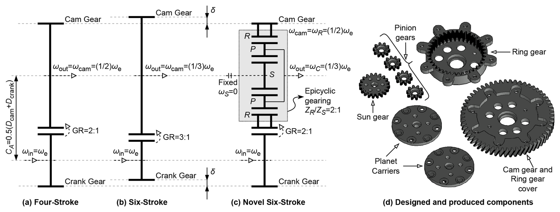
The method proposed in this study involves adding epicyclic gearing to the camshaft without modifying the crankshaft gearing (Fig. 6c). In this way, while maintaining a constant center-to-center distance CA, the camshaft in the six-stroke engine remains the same size as that in the four-stroke engine. The key difference here is that the ring gear in the epicyclic gearing, originally an internal gear, is reconfigured to function as both an internal and an external gear. Consequently, the crankshaft engages with the external portion of the ring gear, designating the ring gear (internal gear) as the input in the epicyclic gearing. In this setup, either the sun gear or the planet carrier must serve as the output.
When the crankshaft rotates at a speed of ωe, the ring gear rotates at a speed of . Under these conditions, the camshaft speed in a six-stroke engine should be . Using Eq. (8), when the sun gear is fixed (ωS=0), the condition : 1 is met. Here, the number of teeth for the ring gear, sun gear, and planet gear are designated as 40, 20, and 10, respectively. According to Eq. (6), the number of planetary gears, NP, is set to 4, with a pressure angle β=45°. Checking the condition in Eq. (7) confirms that it is satisfied for a gear module M=1.7. This M value is selected based on the size of the cam gear from the original four-stroke engine.
In the designed cam gear assembly, MR106ZZ miniature bearings were incorporated into the planetary pinion gears, while 6702ZZ bearings were used to support the connection between the planet carrier and the ring gear. An M12 screw thread was machined to secure the camshaft at the planet carrier output. M4 bolts and nuts were employed for assembling all components. The prototype of this cam gear was initially manufactured using an FDM 3D printer with PLA filament. Following assembly tests on the engine, the gears intended for experimental use were produced using a closed-cabinet FDM printer with PAHT CF15 filament (polyamide with 15 % carbon fiber) (see Fig. 4d). PAHT-CF filament is a specialized material that offers high tensile strength (103.2 MPa at 5 mm min−1), high impact resistance (Izod impact strength: 18.1 kJ m−2), and high service temperature (Vicat softening point of 192 °C under a 50 N load), making it suitable for this type of gear production (BASF, 2024).
The original camshaft includes an exhaust decompression system, a mechanism that reduces engine compression by keeping the exhaust valve open during the pull start, which helps the engine start more smoothly. However, due to the space limitations caused by the cam gear modification, it was not possible to include this system in the camshaft designed for the six-stroke engine. As a result, the exhaust decompression system was excluded from the modified camshaft design.
2.3 Adaptation of valve timing for the six-stroke engine
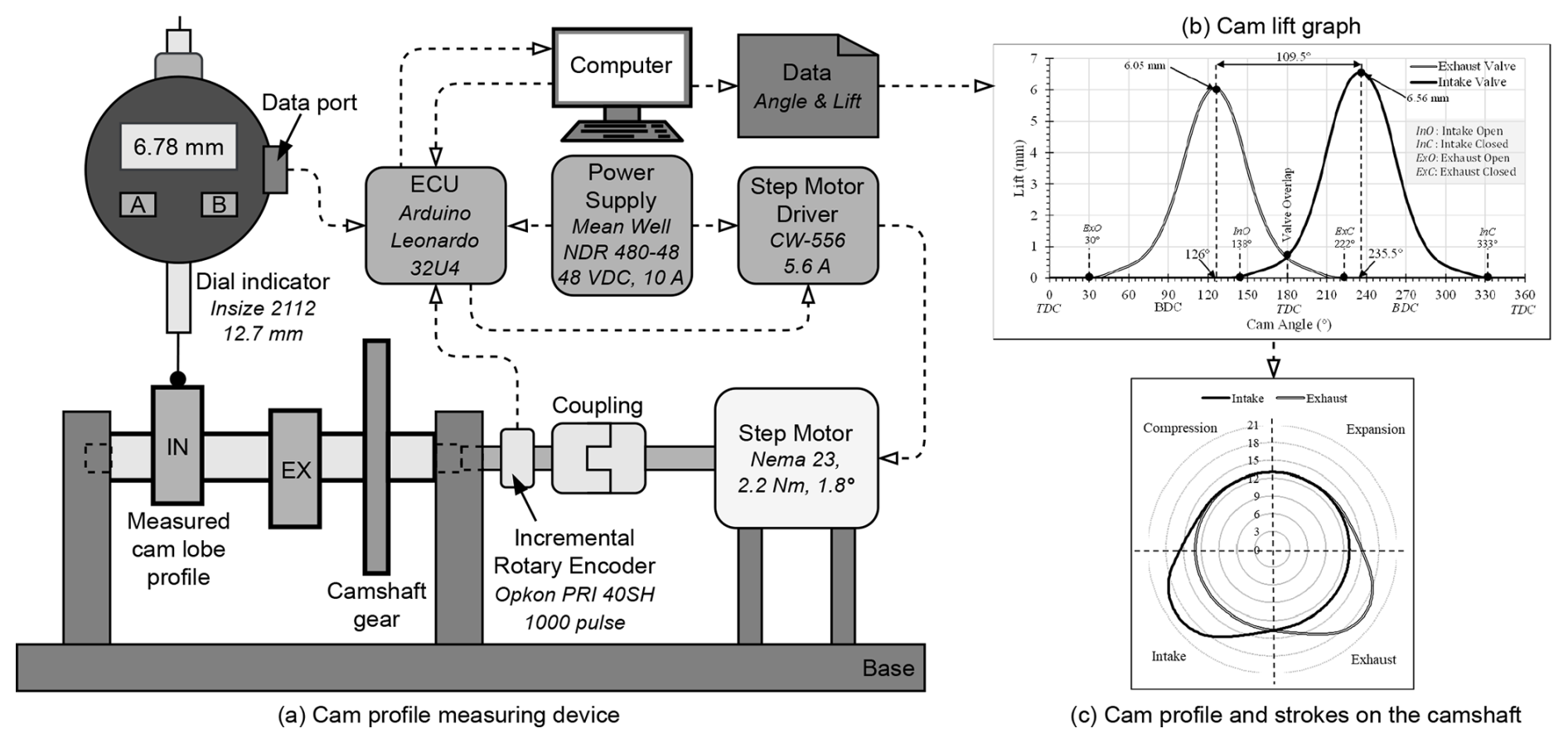
The key step in modifying the camshaft for converting a four-stroke engine to a six-stroke engine lies in adjusting the valve timing. Both intake and exhaust cam profiles, as well as their angular positions on the camshaft, are critical. To measure the profile over the camshaft lobes, a specially manufactured cam profile measurement device was employed (Fig. 7a). This device, equipped with a rotary encoder, collects 1000 data points per rotation. A dial indicator on the device enables high-precision measurements with 0.01 mm accuracy. Data from the dial indicator are captured for each rotary encoder signal and transmitted to a computer through the ECU, allowing for the generation of the cam lift graph (Fig. 7b). This process was conducted for both intake and exhaust cam lobes, resulting in detailed cam profiles (Fig. 7c).
To adapt the cam profiles for the six-stroke engine, it is essential to model the original cam profiles first. The cam follower used in the experiments was designed with a flat surface. For this reason, a two-circular-arc cam profile model, which has been tested for simplicity and reliability, was chosen for the flat-surfaced follower (Arabacı, 2019; Grohe, 1990).
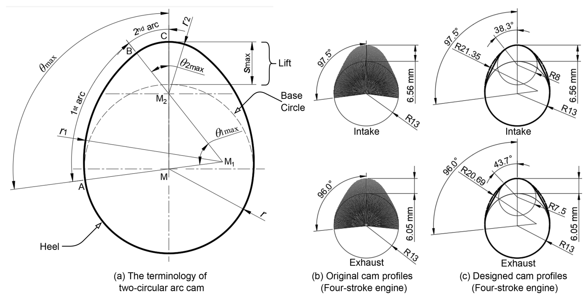
For the design of two-circular-arc cams, the following relationships exist (Arabacı, 2019):
When a flat-faced follower is used, continuous tangential contact is maintained. The contact between the follower and cam takes place at the first arc (AB), the second arc (BC), or the heel (Fig. 8a). The motion of the flat-faced follower takes places only along cam arcs AB and BC. The motion equations for the flat-faced follower are as follows (Grohe, 1990):
The primary dimensions here are r and smax. The critical dimension, however, is b2, which is determined through a trial-and-error method. To determine b2, the average lift save can serve as a reference. Ideally, save should be maximized within the specified boundary conditions. The expression for the average lift is given as follows (Arabacı, 2019):
Here, the choice of b2 affects the angular values and , thereby altering the motion characteristics of the follower. Additionally, for translating follower mechanisms, it is recommended that the acceleration at the peak of the cam, where the follower changes direction, should ideally not exceed 300 m s−2 (Grohe, 1990). Therefore, the value of b2 is limited by the maximum acceleration, amax.
Thus, mm. Another factor in determining b2 is the velocity of the follower at the moment it first moves the valve. According to the workshop manual for the test engine, the clearance values for the intake and exhaust valves are specified to be 0.15 and 0.20 mm, respectively. On the original cam, the angular clearance values (θc) for the intake and exhaust valves are measured to be an 11° camshaft angle (CSA) and a 13° CSA, respectively. For initial contact at these angular values, it is recommended that the follower speed does not exceed 800 mm s−1.
The value of b1 was first determined using Eq. (13) for the condition where followed by checking the clearance values based on Eq. (14). For , the calculated clearance values for the intake and exhaust valves were 0.27 and 0.38 mm, respectively. Since these values did not meet the specifications outlined in the manual, a trial-and-error approach was used to adjust b2 to 8 and 7.5 mm for the intake and exhaust cams, respectively. The equation for calculating follower speed at initial contact is provided below:
Accordingly, the vc values were calculated to be 250.12 and 271.73 mm s−1 for the intake and exhaust followers, respectively. The resulting cam profiles from these calculations are illustrated in Fig. 8c. Based on Eq. (16), the save values for the original cam profiles were determined to be 2.19 and 1.95 mm, respectively. In the redesigned profiles, these values increased by approximately 45 %, reaching 3.17 and 2.83 mm, respectively.
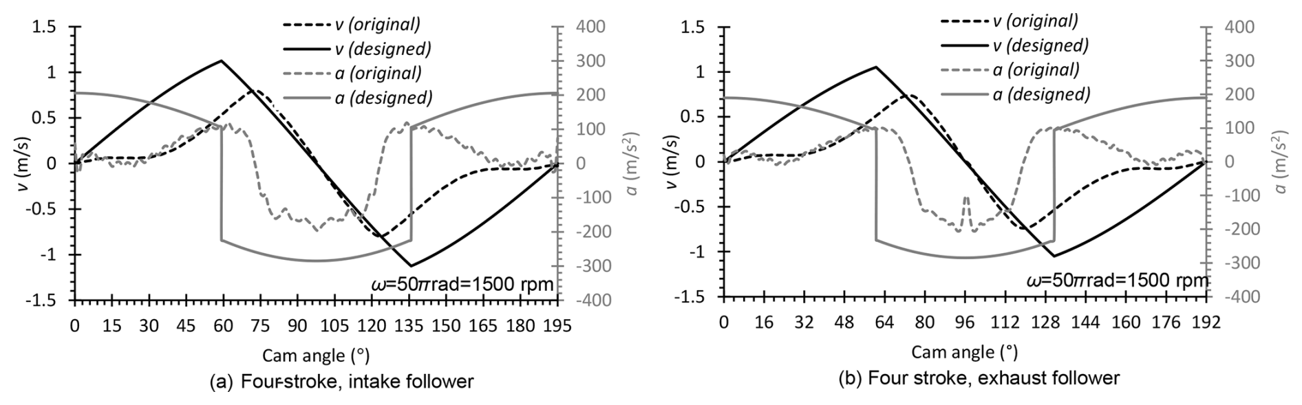
Figure 9Characteristics of the follower motion for the intake and exhaust cams of a four-stroke engine.
Figure 9 shows the motion characteristics of the follower for both the original and the newly designed cam profiles. Although the peak values of velocity and acceleration in the redesigned cam profiles are higher compared to the original, they remain within acceptable limits.
The two-circular-arc cam model used in this study was also applied to the cam profiles of the six-stroke engine. It is well known that a full revolution of the camshaft governs all strokes in the cycle. Theoretically, a stroke on the camshaft occurs at 90° CSA in a four-stroke engine and at 60° CSA in a six-stroke engine (Fig. 10). Consequently, the angular ratio between these two engine types is (Fig. 10).
In practical applications, valves open early and close late to optimize gas exchange efficiency. In a four-stroke engine, the maximum angles (θmax) for the intake and exhaust cams were previously determined to be 97.5 and 96.0° CSA, respectively (see Fig. 10). Applying a angular ratio, the θmax values for the intake and exhaust cams in the six-stroke engine are calculated to be 65 and 64° CSA, respectively. Since this study adopts the Kelem model for the six-stroke engine, the exhaust valve remains open for three strokes. Consequently, the exhaust cam opens at an initial 64° CSA and reaches maximum lift (smax) and closes at a final 64° CSA. During this period, the exhaust valve remains fully open. On the original cam, the clearance angles (θc) for the intake and exhaust valves were measured to be 11 and 13° CSA, respectively. By applying the same 3/2 angular ratio, the clearance angles required to transmit motion to the follower in the six-stroke engine are calculated to be 7.33° CSA for the intake valve and 8.67° CSA for the exhaust valve (see Fig. 11).
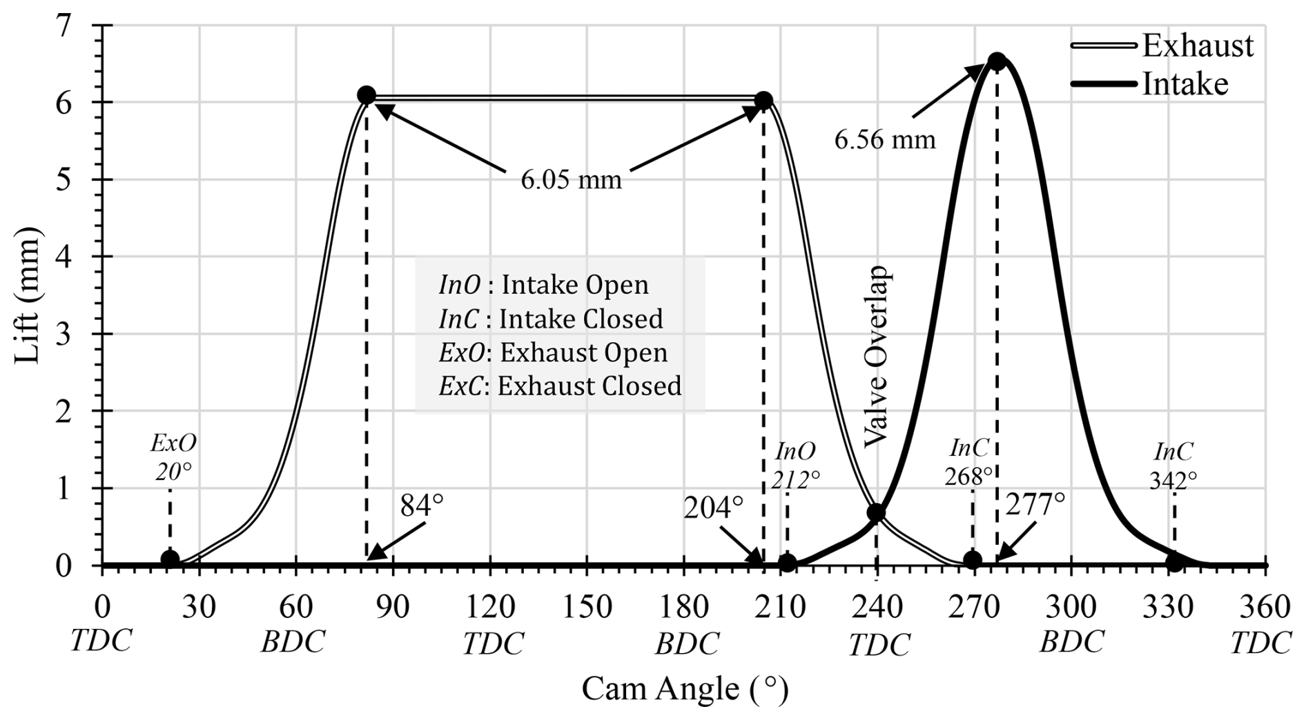
Based on the angular values shown in Fig. 11, cam profiles for the six-stroke engine were designed using the two-circular-arc cam model. Initial trials for developing the six-stroke cam profile began with a base circle radius of r=13 mm as in the original cam profile. However, standard clearance values could not be met within the angular constraints for both intake and exhaust cam profiles. Consequently, through a trial-and-error approach, the intake valve radius was adjusted to r=16 mm and the exhaust valve radius to r=18 mm. This increase in the base circle radius required the modification of the connecting rod between the follower and rocker arm to accommodate the new dimensions. Final adjustments were made using the adjustment screw within the rocker mechanism. As shown in Fig. 11, since the exhaust valve remains open for a total of three strokes, a peak interval rather than a distinct peak is assumed. Under such force-intensive conditions, significant wear is anticipated due to prolonged contact between the cam and follower.
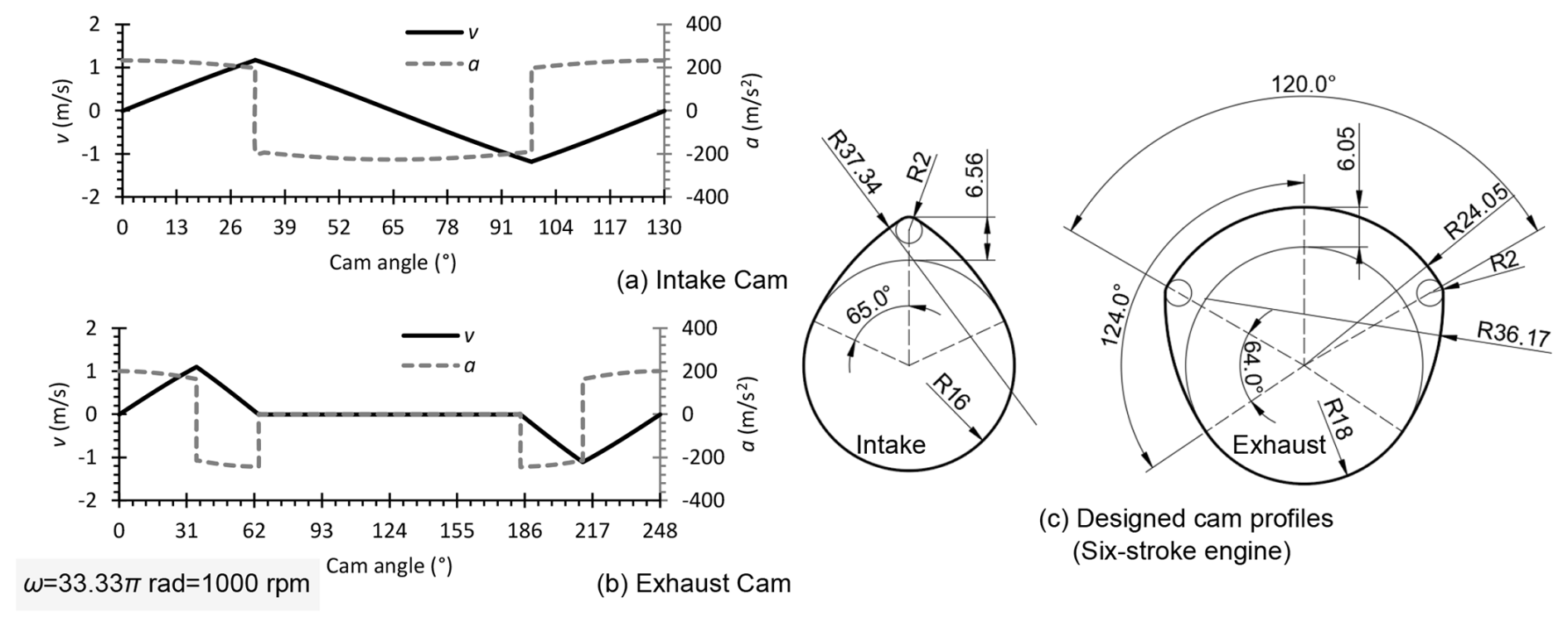
Figure 12 presents the cam profiles designed for the six-stroke engine along with their respective motion characteristics. At a reference engine speed of 3000 rpm, the camshaft speed is 1500 rpm in the four-stroke engine and 1000 rpm in the six-stroke engine. The lower camshaft speed in the six-stroke engine, compared to the four-stroke engine, contributes to improved motion characteristics.
The cam lobes, after the completing their design process, were manufactured from DIN 42CrMoS4 steel and mounted onto an M12 threaded rod using nuts. The assembled camshaft was then integrated into the cam gear, which was designed with epicyclic gearing, preparing the setup for experimental testing
To assess the impact of the two-circular-arc cam model on engine performance, a dedicated camshaft was manufactured for the four-stroke engine incorporating an epicyclic gear train. In this setup, a lock pin secured the ring gear and planet carrier, ensuring the direct transmission of the ring gear's motion. This design allowed for a straightforward comparison of the effects of both the two-circular-arc cam model and epicyclic gearing on the newly produced camshaft. Experimental fuel consumption data, collected over a 400–4000 W resistive load range at an engine speed of 3000 rpm, are presented in Fig. 13. The results indicate a 3.4 % average increase in fuel consumption with the modified camshaft. This increase is likely due to minor deviations in the original cam profile, design constraints of the two-circular-arc cam model, manufacturing tolerances in the epicyclic gearing, and general production limitations.
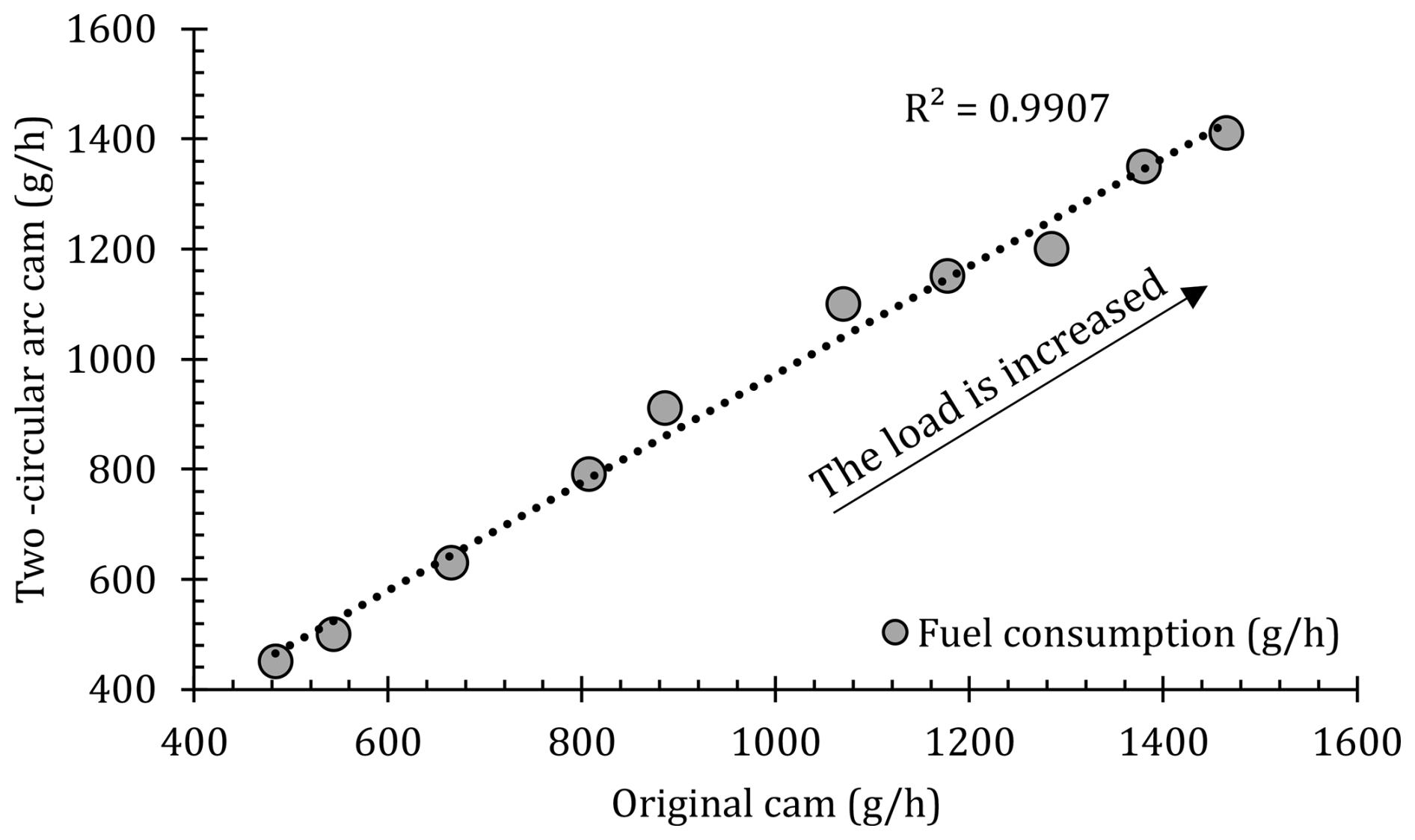
Figure 13Fuel consumption comparison for the original camshaft and produced camshaft in four-stroke engine.
This study compares the fundamental performance metrics of a four-stroke engine with its original camshaft to those of a six-stroke engine modified with epicyclic gearing and a two-circular-arc cam model. Key parameters measured include fuel consumption, oil temperature, and exhaust gas temperature, while thermal efficiency, specific fuel consumption, and fuel consumption per cycle were calculated to further evaluate performance.
The relationship between fuel consumption and applied resistive load is illustrated in Fig. 14. Following the conversion to a six-stroke configuration, fuel consumption decreased by approximately 13.4 %. This reduction is attributed to the longer cycle length of the six-stroke engine, which is 50 % greater than that of the four-stroke engine. As a result, the number of cycles per minute and, consequently, fuel consumption, decreased. At 3000 rpm, the four-stroke engine completes 1500 cycles min−1, whereas the six-stroke engine completes 1000 cycles min−1. While this conversion led to a 33.3 % reduction in cycle frequency, fuel consumption decreased by only 13.4 %. These findings suggest that to maintain the required power output in the experiment, the six-stroke engine's fuel consumption, and therefore its load, must be comparatively higher.
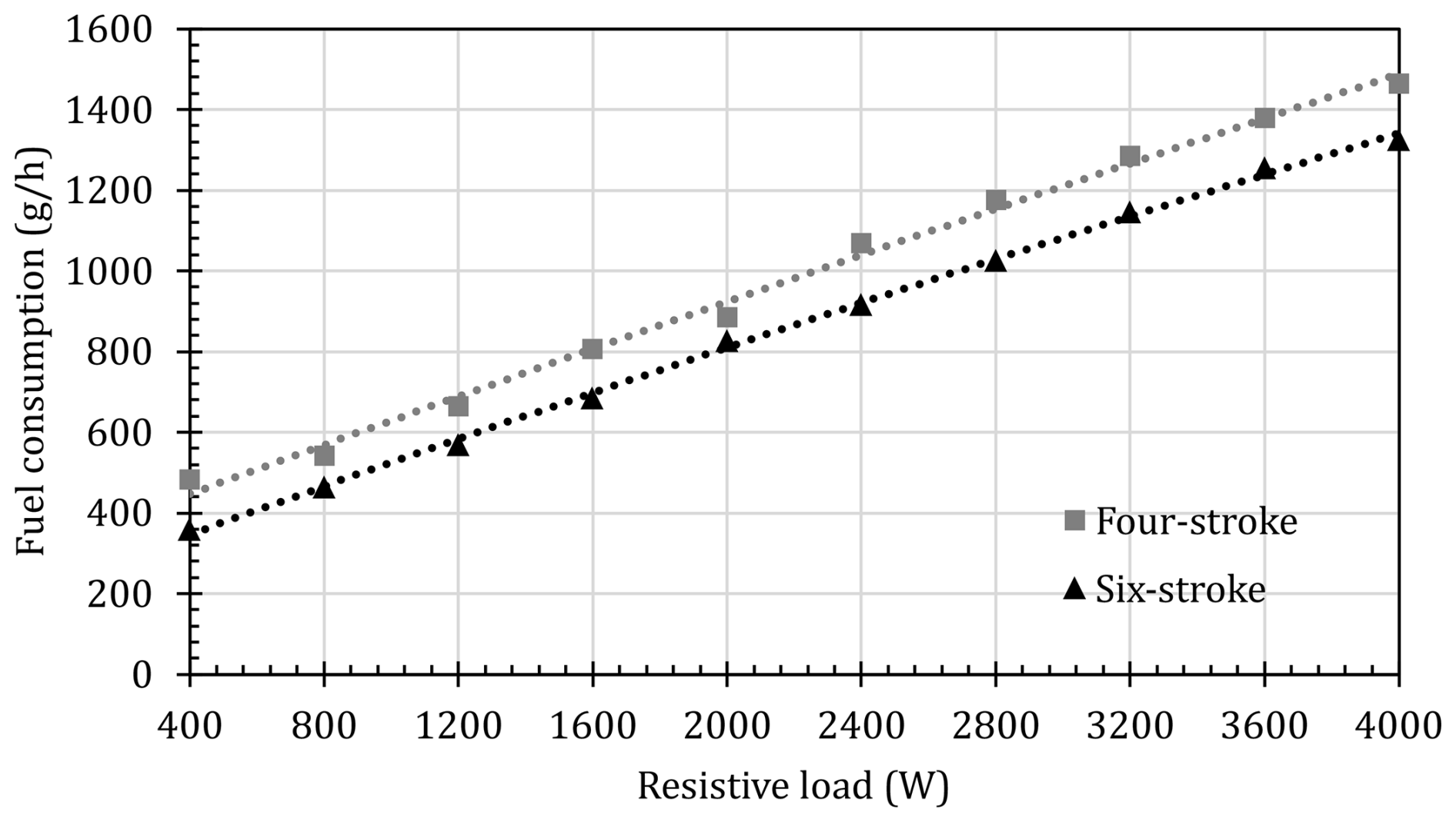
Figure 15 illustrates the change in oil temperature in relation to the applied resistive load. After converting from a four-stroke engine to a six-stroke engine, a decrease of approximately 3.1 % in oil temperature was observed. At first glance, this decrease might seem more significant. However, since the six-stroke engine generates the same power as the four-stroke engine at a higher operating load, it is expected that the oil temperature will not change drastically. To evaluate the oil temperature more accurately, it should be considered in conjunction with specific fuel consumption or thermal efficiency data. In the six-stroke engine, the oil temperature ranges from 326 to 412 K, while in the four-stroke engine, it ranges from 336 to 425 K. As anticipated, the oil temperature increases as the resistive load rises.
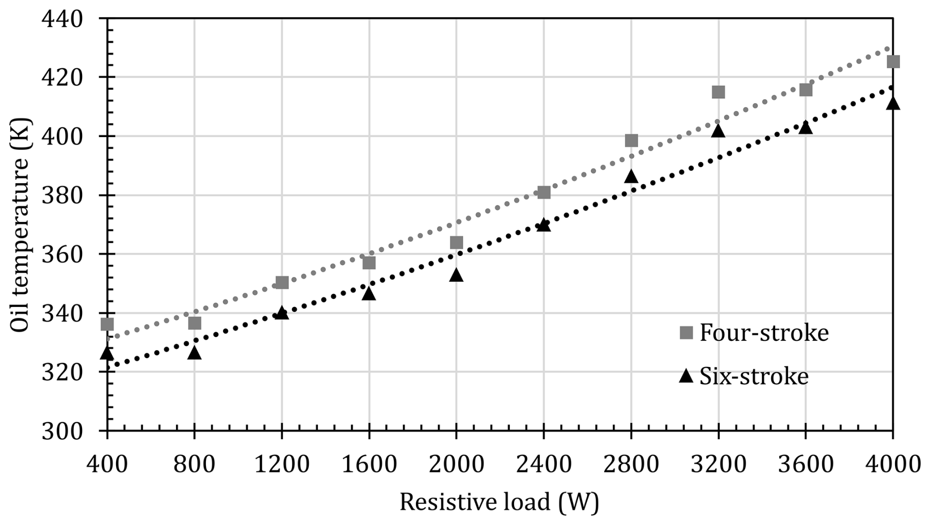
Figure 16 presents the changes in exhaust gas temperature in response to the applied resistive load. After converting from a four-stroke to a six-stroke engine, the exhaust gas temperature decreased by approximately 15.4 %. This reduction is expected as the average exhaust temperature naturally drops due to the additional free strokes following the exhaust stroke in a six-stroke engine. In the six-stroke cycle strategy used in this study, exhaust gases are expelled through the exhaust line during the exhaust stroke. During the first free stroke, the cylinder intakes a mixture of gases (initially residual exhaust gas followed by air) from the exhaust line. Finally, during the second free stroke, the gas in the cylinder is expelled through the exhaust line. During these strokes, the temperature of the exhaust gases in the line decreases slightly. It is important to note that the exhaust temperature here represents an average value and does not capture the peak temperature of the exhaust gases immediately after combustion. Nevertheless, the exhaust temperature of the six-stroke engine remains lower than that of the four-stroke engine.
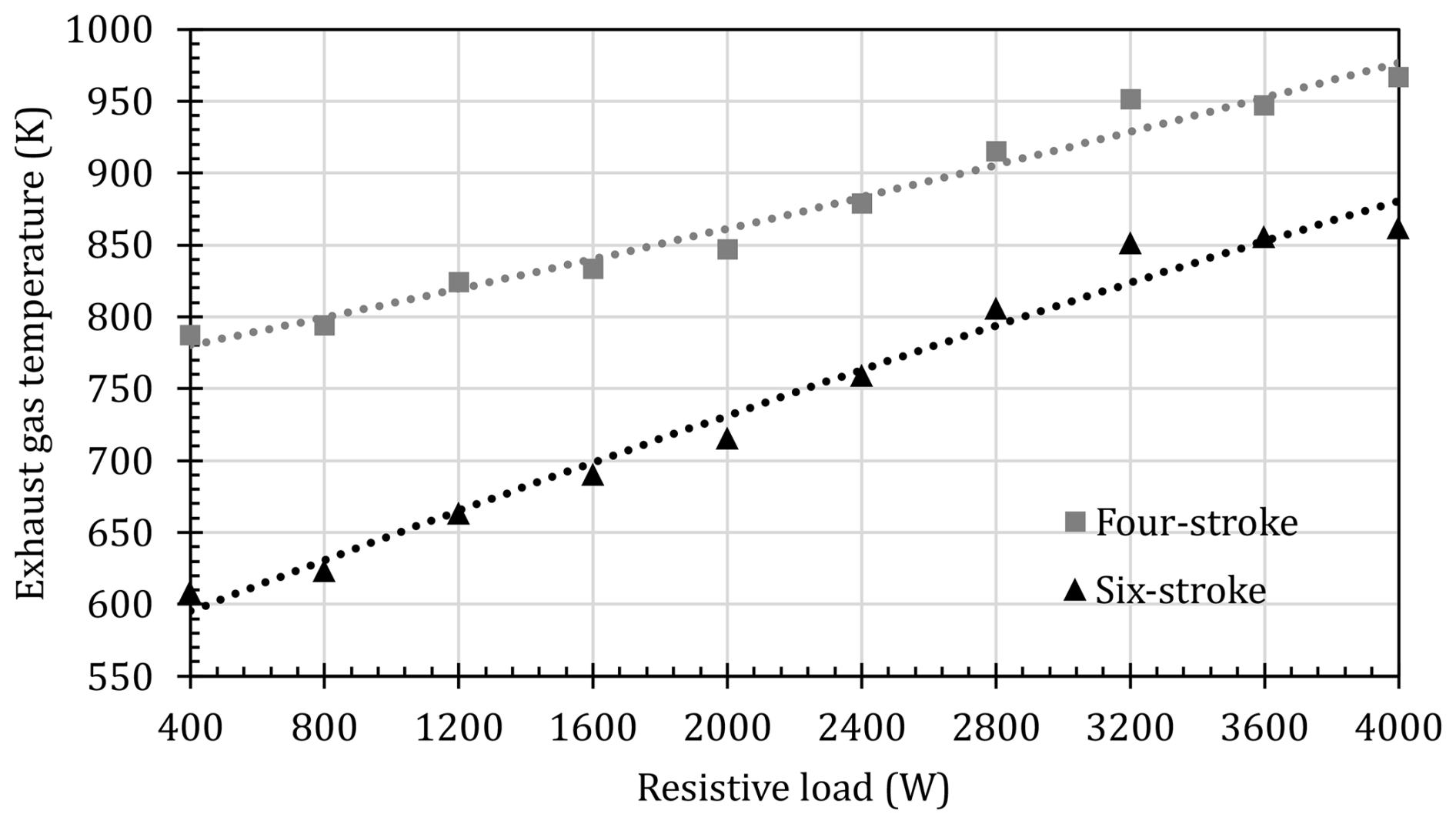
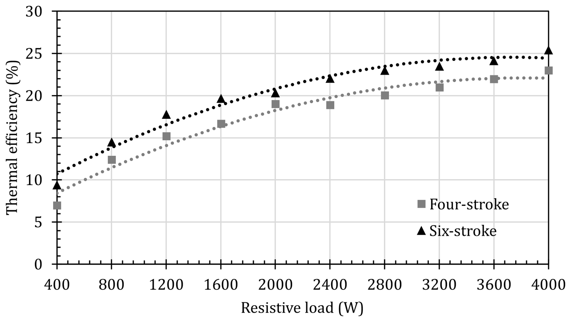
Figure 17 illustrates the variation in thermal efficiency relative to the applied resistive load. After the transition from a four-stroke to a six-stroke engine, thermal efficiency increased by approximately 15.8 %. This improvement is mainly attributed to the six-stroke engine's operation under higher loads compared to the four-stroke engine as thermal efficiency tends to improve with increased engine load. Additionally, another factor contributing to the boost in thermal efficiency is the reduction in in-cylinder temperature and residual gas, which occurs due to the free strokes in the six-stroke cycle. This decrease may enhance both volumetric and combustion efficiency, resulting in a corresponding increase in thermal efficiency.
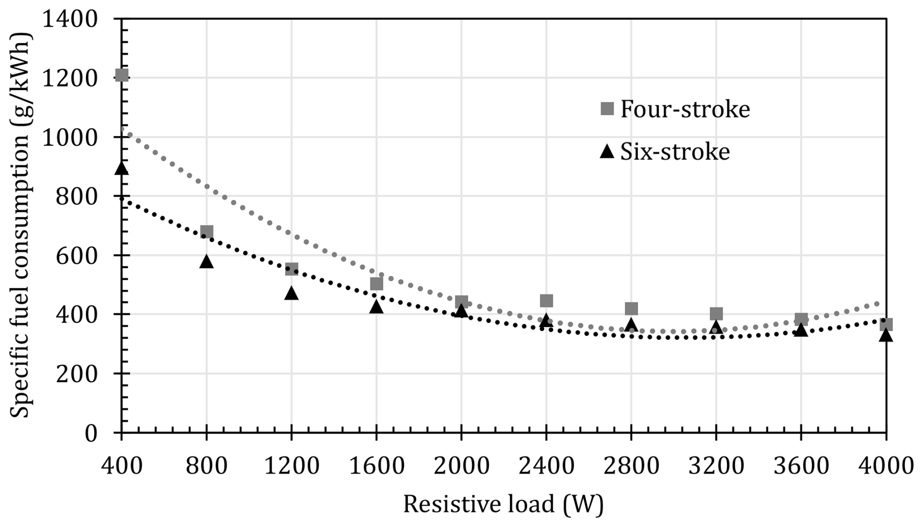
Specific fuel consumption is a key indicator of engine performance. Figure 18 illustrates the variation in specific fuel consumption with increasing resistive load. After converting from a four-stroke to a six-stroke engine, specific fuel consumption decreased by approximately 13.4 %. The advantages of the six-stroke engine are particularly evident at low and medium resistive loads. Notably, in the 2400–3600 rpm range, the specific fuel consumption values for both engines are quite similar. However, the fuel consumption advantage observed at lower resistive loads diminishes as the resistive load increases.
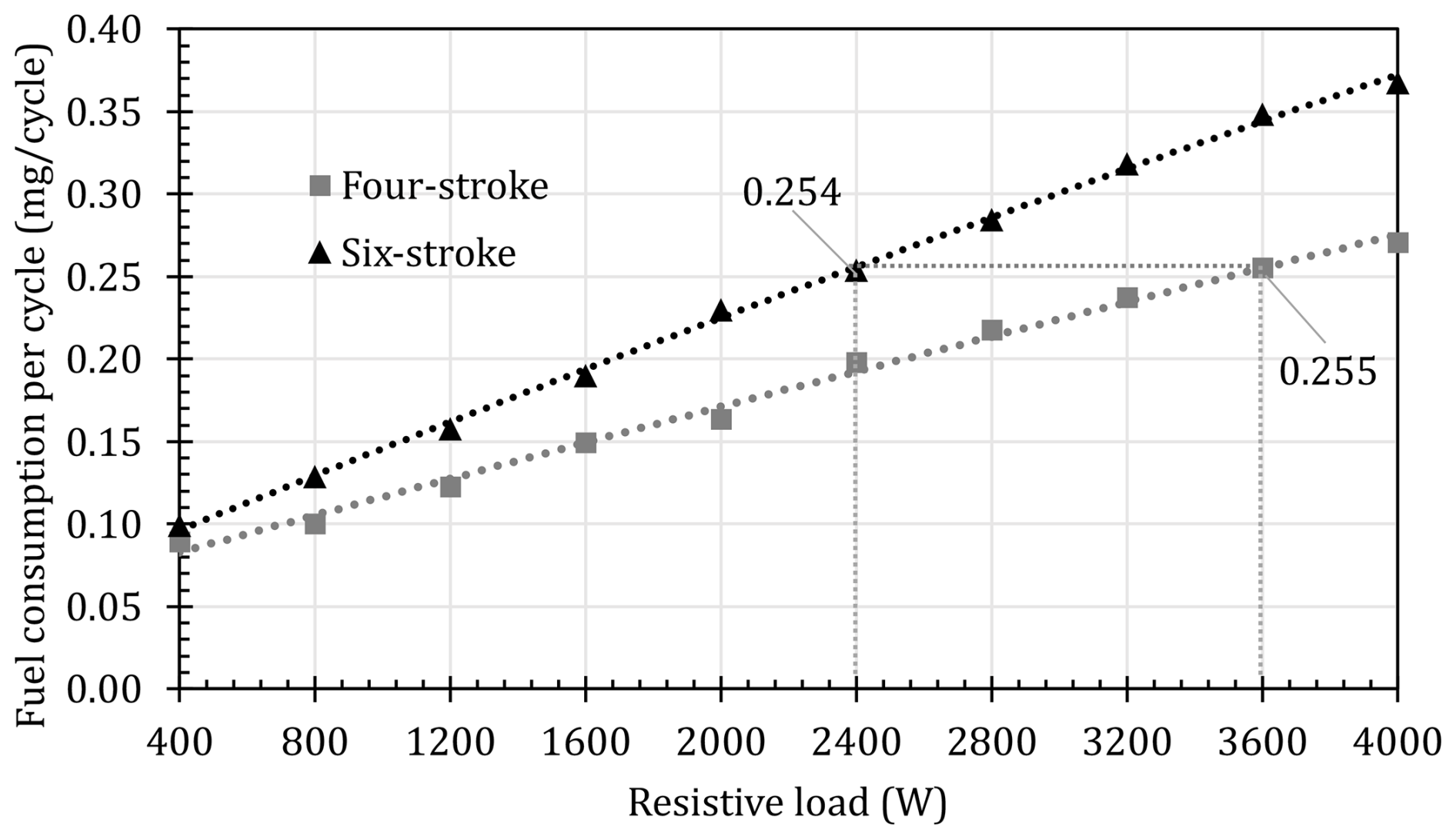
When comparing engines with different working cycles, as in this study, it is essential to evaluate fuel consumption on a per-cycle basis. This comparison is the most meaningful under constant resistive load and fixed engine speed conditions. The cam profiles that control stroke formation in both four-stroke and six-stroke engines exhibit similar characteristics. However, due to the engine's premixed operation (enabled by the carburetor), the air–fuel mixture is drawn in during the intake stroke, with its volume regulated by the carburetor's throttle valve. Therefore, per-cycle fuel consumption is a key parameter in assessing engine performance.
Figure 19 illustrates the relationship between fuel consumption per cycle and the applied resistive load. As expected, per-cycle fuel consumption increases as the load rises. However, since the six-stroke engine completes fewer cycles per unit time than the four-stroke engine at a constant speed, it consumes more fuel per cycle to maintain the same power output. For instance, while a four-stroke engine consumes 255 mg of fuel under a 3600 W resistive load, the six-stroke engine reaches a similar consumption level (254 mg) at only 2400 W. These results indicate that for a six-stroke engine to achieve comparable performance to a four-stroke engine, its per-cycle fuel consumption must be approximately 29.9 % higher.
Previous studies on converting Otto cycle engines to Atkinson cycle engines have shown that increasing the geometric compression ratio and adjusting the valve timing can reduce specific fuel consumption by 8 %–12 % (Feng et al., 2016; Cinar et al., 2021; Niu et al., 2020; Bowyer et al., 2021). While Atkinson cycle engines achieve high efficiency through an extended expansion process, this conversion requires modifications to both the valve timing and the engine's geometric design. In the proposed six-stroke engine concept, similar performance and efficiency are achieved solely by redesigning the camshaft. Although the cam gear mechanism has a complex structure, this modification is considered to be a simpler process compared to altering the engine's geometric compression ratio. This design advantage enhances the potential of six-stroke engines for use in hybrid electric vehicles.
In this study, a camshaft modification is performed to enable the conversion of a four-stroke engine to a six-stroke engine. The Kelem model, a six-stroke engine strategy known for incorporating free strokes, was employed. To achieve the required angular velocity differential between the crankshaft and camshaft, a novel model was applied. In this model, the crankshaft gear remained unchanged, while the camshaft gear was configured with fixed-ratio epicyclic gearing. This setup facilitated the desired speed variation necessary for the six-stroke operation.
Converting a four-stroke engine to a six-stroke engine is a complex and challenging process. For this study, the modification was applied to a conventional single-cylinder, air-cooled engine commonly used in power generators. A significant challenge was the compact assembly of the alternator and engine, making disassembly and reassembly more difficult. Each minor adjustment to the camshaft required detaching and reattaching the alternator, substantially slowing the progress of the experiments.
For the conversion of the conventional four-stroke engine to a six-stroke engine, the original camshaft dimensions were accurately determined, with particular focus on the intake and exhaust cam profiles and valve timing. To achieve precise measurements, a straightforward experimental setup was employed to capture the cam profiles, which were then adapted into a mathematical model known as the two-circular-arc cam model for the six-stroke engine.
A hybrid manufacturing approach was employed, designing the camshaft in three main parts. Due to the high precision required in producing cam gears, 3D-printing technology was utilized to produce components, which were then assembled with miniature bearings and steel shafts for stability. The cam lobes were manufactured using DIN 42CrMoS4 steel, and the camshafts performed reliably throughout testing.
To load the engine, a 4000 W resistive load cell was designed, applying increments of 400 W to the generator while measuring fuel consumption, oil temperature, and exhaust gas temperature. Thermal efficiency, specific fuel consumption, and fuel consumption per cycle were calculated, with an overall experimental uncertainty of 3.22 %. Theoretical analysis indicated that increasing the number of strokes per cycle by 50 % (introducing free strokes) resulted in a 33.33 % reduction in cycle frequency per unit time. To maintain power output, the engine load (throttle opening) had to be increased. Although higher fuel consumption was observed due to the increased load, thermal efficiency improved, leading to a 13.4 % decrease in specific fuel consumption, marking a significant efficiency gain. However, a reduction in peak power was noted, accompanied by lower oil and exhaust gas temperatures due to the extended cycle time. Additionally, thermal efficiency increased by 15.8 %, while fuel consumption per cycle increased by 29.9 %. While this study primarily focused on fundamental performance parameters, in-cylinder pressure variation, intake and exhaust pressure fluctuations, exhaust emissions, vibration, and acoustic emissions were not examined. Furthermore, as the generator operated at a constant speed, the engine speed characteristics were not assessed.
This research was conducted using the measurements and characteristics of the original test engine as reference without further modifications. Parameters such as valve timing and cam profile movement characteristics for six-stroke operation were not analyzed, leaving room for future studies to explore alternative six-stroke strategies. Additionally, integrating epicyclic gearing into the camshaft while maintaining the original crankshaft gear posed challenges due to space constraints, particularly in compact engines. Future studies may consider positioning this gear mechanism outside the engine to overcome such limitations.
The six-stroke engine approach presented here is one of the simplest methods in the literature. However, its applicability to both premixed and direct-injection engines is a significant advantage. Nonetheless, the continuous opening of the exhaust valve may cause flow disruption in the exhaust system, which should be taken into consideration. Therefore, in future studies, alternative approaches developed as substitutes for this method could also be evaluated (Arabacı and Içingür, 2016). The main innovation in this study lies in the novel approach to the cam gear. For future research, the applicability of variable valve timing strategies used in Atkinson cycle engines to six-stroke engines could be explored. Additionally, to leverage the advantages of four-stroke engines, a series of design modifications to the camshaft could enable the development of a dual-cycle engine capable of operating in both four-stroke and six-stroke modes.
In this study, the change in engine performance is examined without altering the valve timing characteristics. However, in future studies, the impact of different valve timing characteristics on engine performance in the six-stroke engine concept can be analyzed in detail. In particular, the potential effects of various valve timing strategies on combustion efficiency, power output, and emission levels can be investigated. Furthermore, the application of this study to multi-cylinder engines can also be explored while considering the possible advantages and design requirements. This would allow for a more comprehensive evaluation of how the six-stroke engine concept performs across different engine configurations.
In conclusion, this study demonstrates that a four-stroke engine can be successfully converted to six-stroke operation, achieving fuel savings at the cost of reduced power output. The implementation of epicyclic gearing for the camshaft while preserving the original crankshaft gear, along with the experimental validation of this approach, underscores its potential and highlights its advantages over existing methods in the literature.
The corresponding authors can provide all raw data upon request.
EA conceptualized the study, analyzed the data, and reviewed and edited the manuscript. MA reviewed the literature and designed and produced the components. EA and MA developed the methodology, designed the experiment, performed the measurements, and wrote the manuscript draft.
The contact author has declared that neither of the authors has any competing interests.
Publisher's note: Copernicus Publications remains neutral with regard to jurisdictional claims made in the text, published maps, institutional affiliations, or any other geographical representation in this paper. While Copernicus Publications makes every effort to include appropriate place names, the final responsibility lies with the authors.
This study was supported by Pamukkale University (Türkiye) through the Scientific Research Projects Coordination (PAUBAP/Türkiye) under project code 2022FEBE059. As researchers, we would like to express our gratitude to PAUBAP/Türkiye. This paper is based on the master's thesis titled “Camshaft Modification for Conversion of Four-Stroke Engines to Six-Stroke Engines” completed by the authors at Pamukkale University in 2024.
This research has been supported by Pamukkale University (grant no. PAUBAP 2022FEBE059).
This paper was edited by Wuxiang Zhang and reviewed by Mohammad Naeim Moradi and two anonymous referees.
Arabaci, E.: Dimensionless design approach to translating flat faced follower mechanism with two-circular-arc cam, Mech. Sci., 10, 497–503, https://doi.org/10.5194/ms-10-497-2019, 2019.
Arabacı, E.: Performance analysis of a novel six-stroke Otto cycle engine, Therm. Sci., 25, 1719–1729, https://doi.org/10.2298/TSCI190926144A, 2021.
Arabacı, E.: Extended cycle internal combustion engine, Türk Patent No. 2018/09147, Turkish Patent and Trademark Office, 2022.
Arabacı, E. and İçingür, Y.: Thermodynamic investigation of experimental performance parameters of a water injection with exhaust heat recovery six-stroke engine, J. Energy Inst., 89, 569–577, https://doi.org/10.1016/j.joei.2015.06.006, 2016.
Arabacı, E. and İçingür, Y.: Cam mechanism for six-stroke engine conversions, Türk Patent No. 2018/02257, Turkish Patent and Trademark Office, 2021.
Arabacı, E. and Kılıç, B.: Novel over-expanded six-stroke engine mechanism, Bitlis Eren Üniversitesi Journal of Science, 7, 320–338, https://doi.org/10.17798/bitlisfen.428198, 2018.
Arabacı, E., İçingür, Y., Solmaz, H., Uyumaz, A., and Yilmaz, E.: Experimental investigation of the effects of direct water injection parameters on engine performance in a six-stroke engine, Energ. Convers. Manage., 98, 89–97, https://doi.org/10.1016/j.enconman.2015.03.045, 2015.
Asef, A., Ajami Kashani, N., Parivar, A., Zakeri, E., and Mohsenirad, M.: Conceptual and experimental study of an Atkinson cycle engine of a Series-Parallel hybrid electric vehicle, Journal of Engine Research, 70, 69–80, https://doi.org/10.22034/er.2024.2025131.1041, 2024.
BASF: PAHT-CF filament, BASF, https://forward-am.com/material-portfolio/ultrafuse-filaments-for-fused-filaments-fabrication-fff/reinforced-filaments/ultrafuse-paht-cf15/, last access: 11 September 2024.
Bowyer, S., Ortiz-Soto, E., Younkins, M., and Venkadasamy, V.: Evaluation of New High Efficiency Engine Concept with Atkinson Cycle, Cooled EGR and Dynamic Skip Fire, No. 2021-01-0459, SAE Technical Paper, https://doi.org/10.4271/2021-01-0459, 2021.
Chen, H., Guo, Q., Yang, L., Liu, S., Xie, X., Chen, Z., and Liu, Z.: A new six stroke single cylinder diesel engine referring Rankine cycle, Energy, 87, 336–342, https://doi.org/10.1016/j.energy.2015.04.107, 2015.
Cinar, C., Ozdemir, A. O., Gulcan, H. E., and Topgül, T.: Theoretical and experimental investigation of the performance of an Atkinson cycle engine, Arab. J. Sci. Eng., 46, 7841–7850, https://doi.org/10.1007/s13369-021-05595-7, 2021.
Conklin, J. C. and Szybist, J. P.: A highly efficient six-stroke internal combustion engine cycle with water injection for in-cylinder exhaust heat recovery, Energy, 35, 1658–1664, https://doi.org/10.1016/j.energy.2009.12.012, 2010.
Desreveaux, A., Bouscayrol, A., Trigui, R., Hittinger, E., Castex, E., and Sirbu, G. M.: Accurate energy consumption for comparison of climate change impact of thermal and electric vehicles, Energy, 268, 126637, https://doi.org/10.1016/j.energy.2023.126637, 2023.
Dyer, L.: Internal combustion engine, U.S. Patent No. 1339176, U.S. Patent and Trademark Office, 1920.
Farzaneh, F. and Jung, S.: Lifecycle carbon footprint comparison between internal combustion engine versus electric transit vehicle: A case study in the US, J. Clean. Prod., 390, 136111, https://doi.org/10.1016/j.jclepro.2023.136111, 2023.
Fenfeo Automation Private Limited: Emissions of electric vehicle vs. hybrid electric vehicle vs. combustion engine vehicle, Fenfeo Automation Private Limited, https://www.rapidevcharge.com/emissions-of-electric-vehicle-vs-hybrid-electric-vehicle-vs-combustion-engine-vehicle/, last access: 11 August 2024.
Feng, R., Li, Y., Yang, J., Jianqin, F. U., Zhang, D., and Zheng, G.: Investigations of Atkinson cycle converted from conventional Otto cycle gasoline engine, No. 2016-01-0680, SAE Technical Paper, https://doi.org/10.4271/2016-01-0680, 2016.
Gabora, A. B. M.: Six stroke internal combustion engine, WIPO Patent No. WO2013038228A1, World Intellectual Property Organization, 2013.
Grand View Research: Internal combustion engine market size, share & trends analysis report by fuel type (petroleum, natural gas), by end-use (automotive, marine, aircraft), by region, and segment forecasts, 2023–2030, Grand View Research, Report ID: 978-1-68038-591-5, https://www.grandviewresearch.com/industry-analysis/internal-combustion-engine-market (last access: 10 April 2024), 2024.
Griffin, S.: Method of operating gas engines, U.S. Patent No. 412883, U.S. Patent and Trademark Office, 1889.
Grohe, H.: Otto-und Dieselmotoren: Arbeitsweise, Aufbau und Berechnung von Zweitakt- und Viertakt-Verbrennungsmotoren, Vogel, Würzburg, Germany, ISBN 9783802911631, 1990.
Gupta, K., Suthar, K., Jain, S. K., Agarwal, G. D., and Nayyar, A.: Design and experimental investigations on six-stroke SI engine using acetylene with water injection, Environ. Sci. Pollut. R., 25, 23033–23044, https://doi.org/10.1007/s11356-018-2407-2, 2018.
Holman, J. P.: Experimental Methods for Engineers, 8th edn., McGraw-Hill, New York, USA, ISBN 9780073398206, 2021.
Honda Engines: Power Units, GX390, Honda Engines, https://www.honda-engines-eu.com/en/products/power-units/gx390, last access: 12 April 2024.
Huang, H., Liu, Q., Yang, R., Zhu, T., Zhao, R., and Wang, Y.: Investigation on the effects of pilot injection on low temperature combustion in high-speed diesel engine fueled with n-butanol–diesel blends, Energy Convers. Manage., 106, 748–758, https://doi.org/10.1016/j.enconman.2015.10.031, 2015.
Kanna, V. I. and Pinky, D.: Investigation of the effects of exhaust and power loss in dual-fuel six-stroke engine with EGR technology, Int. J. Ambient Energy, 41, 1270–1275, https://doi.org/10.1080/01430750.2018.1507942, 2020.
Kelem, H. and Kelem, E.: Six stroke internal combustion engine method of operation, U.S. Patent No. 2010/0095913, U.S. Patent and Trademark Office, 2010.
Liedtke, H.: Internal combustion and steam engine, U.S. Patent No. 1217788, U.S. Patent and Trademark Office, 1917.
Nayyar, A., Sharma, D., Soni, S. L., and Mathur, A.: Experimental investigation of performance and emissions of a VCR diesel engine fuelled with n-butanol diesel blends under varying engine parameters, Environ. Sci. Pollut. R., 24, 20315–20329, https://doi.org/10.1007/s11356-017-9599-8, 2017.
Niu, Q., Sun, B., Zhang, D., and Luo, Q.: Research on performance optimization and fuel-saving mechanism of an Atkinson cycle gasoline engine at low speed and part load, Fuel, 265, 117010, https://doi.org/10.1016/j.fuel.2020.117010, 2020.
Özdemir, A. O., Uysal, L. K., Menküç, R., and Arabacı, E.: Quasi-Realistic Performance Analysis of Modern Atkinson Cycle, Int. J. Automot. Sci. Technol., 6, 347–356, https://doi.org/10.30939/ijastech..1184658, 2022.
Rajput, O., Ra, Y., and Ha, K. P.: Numerical parametric study of a six-stroke gasoline compression ignition (GCI) engine combustion, No. 2019-01-0207, SAE Technical Paper, https://doi.org/10.4271/2019-01-0207, 2019.
Rajput, O., Ra, Y., Ha, K. P., and Kim, H. W.: Numerical parametric study of a six-stroke gasoline compression ignition (GCI) engine combustion-Part II, No. 2020-01-0780, SAE Technical Paper, https://doi.org/10.4271/2020-01-0780, 2020.
Rajput, O., Ra, Y., Purushothaman, A. K., and Ha, K. P.: Numerical parametric study of a six-stroke gasoline compression ignition (6S-GCI) engine combustion-Part III, No. 2021-01-0401, SAE Technical Paper, https://doi.org/10.4271/2021-01-0401, 2021.
Schimanek, E.: Combustion engine, U.S. Patent No. 1068173, U.S. Patent and Trademark Office, 1913.
Thatoi, D. N. and Gaur, S.: Design and thermal analysis of six stroke engine, Mater. Today Proc., 81, 540–542, https://doi.org/10.1016/j.matpr.2021.03.704, 2023.
Uyumaz, A., Kilmen, A. B., and Kaş, M.: An experimental study of the influences of lacquer thinner addition to gasoline on performance and emissions of a spark ignition engine, Eng. Perspect., 4, 54–59, https://doi.org/10.29228/eng.pers.75965, 2024.
Van Basshuysen, R. and Schäfer, F. (Eds.): Internal Combustion Engine Handbook, SAE International, Warrendale, PA, USA, ISBN 9780768011398, 2016.
Verma, S., Mishra, S., Gaur, A., Chowdhury, S., Mohapatra, S., Dwivedi, G., and Verma, P.: A comprehensive review on energy storage in hybrid electric vehicle, J. Traffic Transp. Eng., 8, 621–637, https://doi.org/10.1016/j.jtte.2021.09.001, 2021.
Winkler, S. L., Anderson, J. E., Garza, L., Ruona, W. C., Vogt, R., and Wallington, T. J.: Vehicle criteria pollutant (PM, NOx, CO, HCs) emissions: How low should we go?, npj Clim. Atmos. Sci., 1, 1–5, https://doi.org/10.1038/s41612-018-0037-5, 2018.
Yang, Y., Yi, H., Yang, S., and Park, S.: Challenges and feasibility of a six-stroke engine using water direct injection, Appl. Therm. Eng., 230, 120753, https://doi.org/10.1016/j.applthermaleng.2023.120753, 2023.
Zhang, F., Wang, L., Coskun, S., Pang, H., Cui, Y., and Xi, J.: Energy management strategies for hybrid electric vehicles: Review, classification, comparison, and outlook, Energies, 13, 3352, https://doi.org/10.3390/en13133352, 2020.