the Creative Commons Attribution 4.0 License.
the Creative Commons Attribution 4.0 License.
 | 07 Jul 2025
Effect of fiber orientation on the kinematical behaviors of a braided continuum manipulator
Xingtao Hu
Le Yin
Jiarui Chen
Zhikai Zhou
Soft continuum manipulators show great promise in minimal invasive surgery (MIS) due to their excellent adaptability and contact safety, but their large volume and nonlinear actuation behavior pose significant challenges. In our recent work, a novel braided manipulator based on fibrous materials has been developed. By employing a hybrid braiding pattern, the manipulator features a thin-walled structure and a linear actuation response, enhancing its suitability for surgical environments. Despite these advancements, the effect of a key design parameter, the fiber orientation, on the manipulator's kinematic behavior remains unclear. This paper investigates the influence of fiber orientation through quantitative analysis of the kinematics of multiple manipulator specimens. Based on these results, design guidelines for braided manipulator skeletons are established. Furthermore, numerical simulations provide deeper insights into kinematic behavior by examining local fiber deformation, revealing that bending motions are significantly influenced by local fiber orientation changes. Additionally, effects of other parameters, such as fiber number and fiber diameter, are also analyzed through simulations. The findings of this study provide a foundation for an optimized design of braided manipulator skeletons.
- Article
(7790 KB) - Full-text XML
- BibTeX
- EndNote


By imitating the continuous structure of living organisms, such as elephant trunks, snakes, and octopus tentacles, continuum robots exhibit high adaptability and flexibility. Due to delicate flexible bodies, continuum robots can realize long-distance stretching in narrow and tortuous environments, overcoming the limitations of traditional rigid robots in confined spaces (Russo et al., 2023). Consequently, continuum robots have attracted widespread attention in a variety of fields, such as medical surgery, industrial automation, rescue, and exploration (Zhang et al., 2022). For example, in minimally invasive surgery (MIS), serpentine endoscopes can navigate along the natural lumen of the human body. This approach significantly reduces the risks associated with invasive surgery, minimizes surgical trauma, and shortens recovery time (Gifari et al., 2019).
Recently, continuum robots show a tendency of softening their backbones. Early traditional continuum robots were in the rigid structure stage, which was assembled by discrete joints and rigid linkages (Russo et al., 2023). These robots have high load capacities but limited degrees of freedom, limiting their adaptability in complex environments (Moran, 2007). Rigid–flexible coupling designs then come into view, which had semi-rigid continuum structures and could enter a semi-rigid transition stage. Li et al. (2017) proposed a new tendon-driven continuum robot based on a coil spring skeleton. It achieved a good flexibility under the redundant actuation through eight independent tendons. Recently, continuum robots with fully flexible materials such as silica gel, hydrogel, and shape memory polymers have become a research hotspot (Chen et al., 2022). Their high safety shows great promise in human–machine interaction environments such as surgery and rehabilitation fields (Gifari et al., 2019). Liu et al. (2023) developed a magnetic soft continuum micro-robot for manipulation and measurement at the microscale, whose magnetic end effector enabled accurate control of the acting force. Cianchetti et al. (2014) designed a pneumatic manipulator based on silicone material. It was actuated by its three air chambers, which occupied a large volume, adding difficulty in its miniaturization. To save volume, cables (Wang et al., 2016) and rods (Wang et al., 2022) have also been applied to the silicone-based manipulators. However, excessive deformation was witnessed, where the strong nonlinear response behavior hindered its accurate control. Yang et al. (2018) proposed a soft silicone robotic arm driven by shape memory alloy (SMA) coils. To purchase a good accuracy, Hall sensors were installed on its tip, and proportional–integral–derivative (PID) controllers were employed, increasing the complexity of the manipulator's control system.
Nowadays, textile robots have appeared which have the advantage of their dramatically deformability (Sanchez et al., 2021). As a kind of textile, a braided structure is formed of two sets of yarns interwoven along a helical path (Hopper et al., 1995). Its mesh configuration makes the structure lightweight and thin-walled (Rawal et al., 2015). More importantly, it allows the structure to bend flexibly and deploy in the radial direction (Hassan et al., 2017). It has been widely used as cardiovascular and esophageal stents in industry applications (Kim et al., 2008; Dua, 2017) and has been designed to resemble worm-like robots (Manfredi et al., 2019; Kim, 2018) and McKibben muscles (Paterna et al., 2022). Additionally, the braided structure has been tried to be designed as a manipulator. Paolo Dario's team (Laschi et al., 2012) designed a braided robot arm inspired by the octopus, which was actuated by the SMA actuators located in its inner channel. The blocked channel makes it difficult to apply in MIS. Stoy et al. (2021) actuated the braided manipulator using cables. Owing to the deployability of the braiding structure, its profile collapsed terribly under the cables' compression. In our recent work entitled “A variable-stiffness continuum manipulator using fibrous structure: design, modeling, and validation”, utilizing the different deployability at hybrid fiber orientations, a dual-layer braided manipulator has been proposed. Its hybrid pattern reduces the structural deployability through deformation conflicts, enabling great profile stability under cable actuation. The resultant constant-curvature bending deformation, linear actuation response, and thin-walled configuration add additional promise in MIS. However, the effects of the fiber orientations on the manipulator's kinematical behaviors have not been investigated, resulting in a lack of a guideline for skeleton design and parameter optimization.
This paper aims to analyze the effects of key structural parameters on the kinematical behaviors of the braided manipulator. The paper is organized as follows. The design method and theoretical analysis of the braided manipulator are described in Sect. 2. Section 3 analyzes the experimental results of the kinematical tests under various design parameters. In Sect. 4, numerical analysis is performed to declare the deformation details and study other braiding parameters' effects. Finally, conclusion is given in Sect. 5, which ends this paper.
In the braided manipulator, the braided tube serves as the structural skeleton, which is formed by multiple helical fibers interwoven together. As described in Fig. 1a, a vital parameter of the braided tube is the fiber orientation. It is expressed by the braiding angle β, which is the included angle between the fiber path and the tube profile plane. Due to the large angle typically over 20°, the braided tube exhibits radial expansion under longitudinal compression, as illustrated in Fig. 1b. It is assumed that the fibers are inextensible and thus maintain a constant length; the expanded tube's length and diameter can be calculated by
where L and D are, respectively, the length and diameter of the braided structure; initial parameters are denoted with a subscript 0. Based on Eq. (1), the differential relationship between the diameter and length can be written as
According to the relationship, an increase in the braiding angle results in a greater radial expansion of the braided tube upon compression. By substituting Eq. (1) into Eq. (2), the expansion can be obtained as
where d characterizes the extent of radial expansion for a given compression ratio .
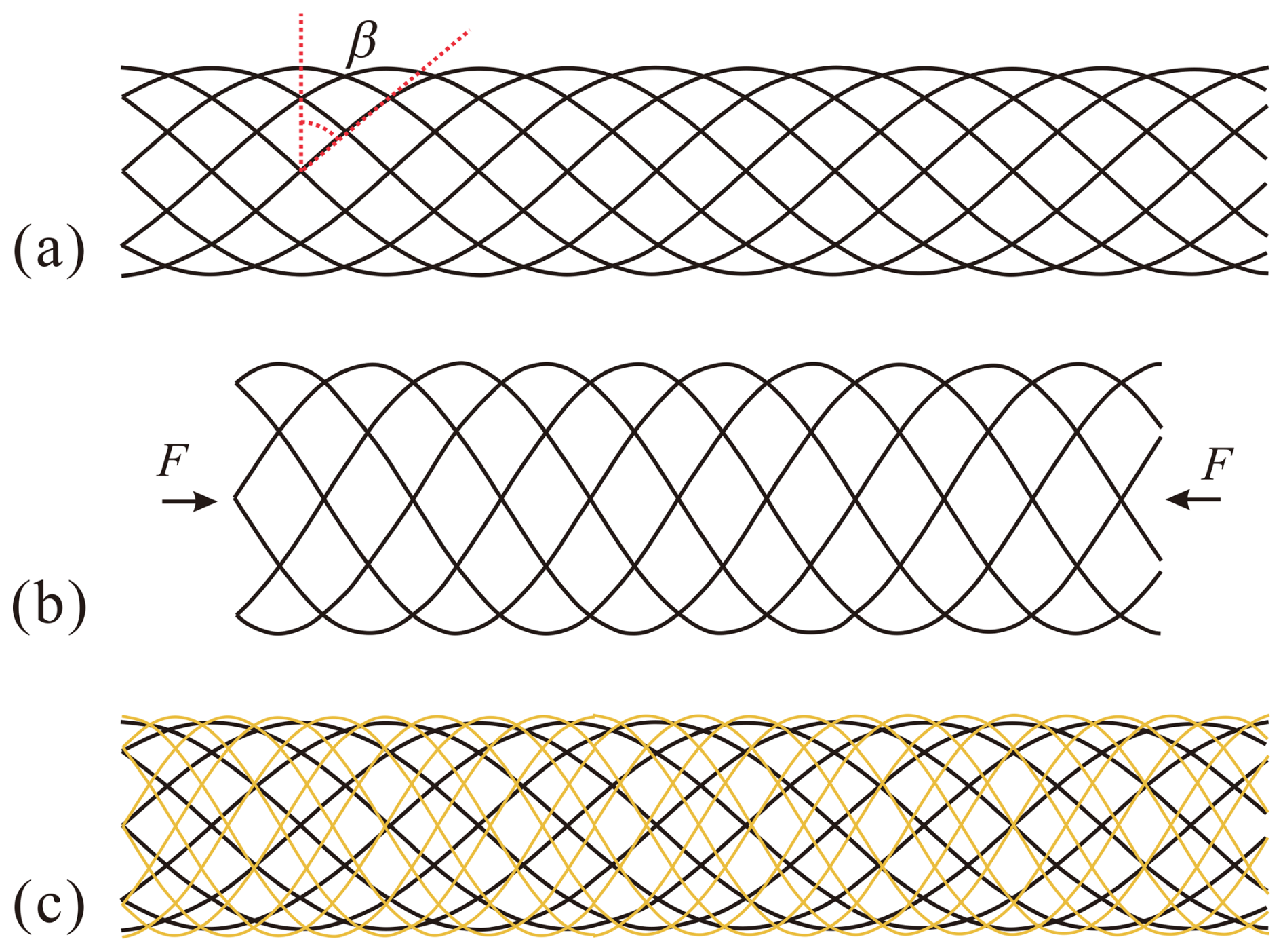
Figure 1Design of the braided manipulator skeleton: (a) single-layer braided tube and its (b) radial expansion under compression and (c) dual-layer braided tube with a larger inner braiding angle.
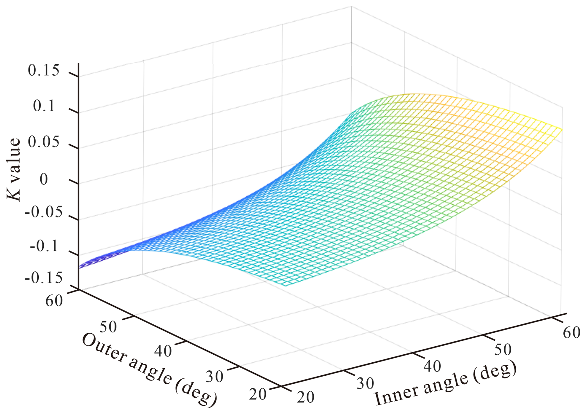
In the case of a dual-layer braided tube with hybrid braiding angles, as shown in Fig. 1c, the outer layer possesses a smaller braiding angle compared with that of the inner layer, and the two layers undergo conflicting expansion deformations. Consequently, the outer layer constrains the radial expansion of the inner layer, thereby maintaining a stable overall profile under the actuation of tensile cables. Neglecting the influence of tube thickness, the two layers share the same diameter and length, and a parameter K could be introduced to quantify the disparity in radial expansion between the two layers, defined as
where subscripts 1 and 2 denote parameters for the outer and inner layers, respectively. At a compression ratio ε of 5 %, the parameter K can be computed using Eq. (4) and plotted in Fig. 2. The results indicate that parameter K assumes a positive value only when the inner layer has a larger braiding angle than the outer layer, demonstrating the restrictive effect of the outer layer on radial expansion. When the angle difference reaches a maximum of 40°, parameter K attains its peak value of 11.9 %, which implies that the difference in radial expansion increases by 11.9 % at a 5 % longitudinal compression. This finding validates the strong radial expansion-constraining effect of the outer layer.
3.1 Experimental setup
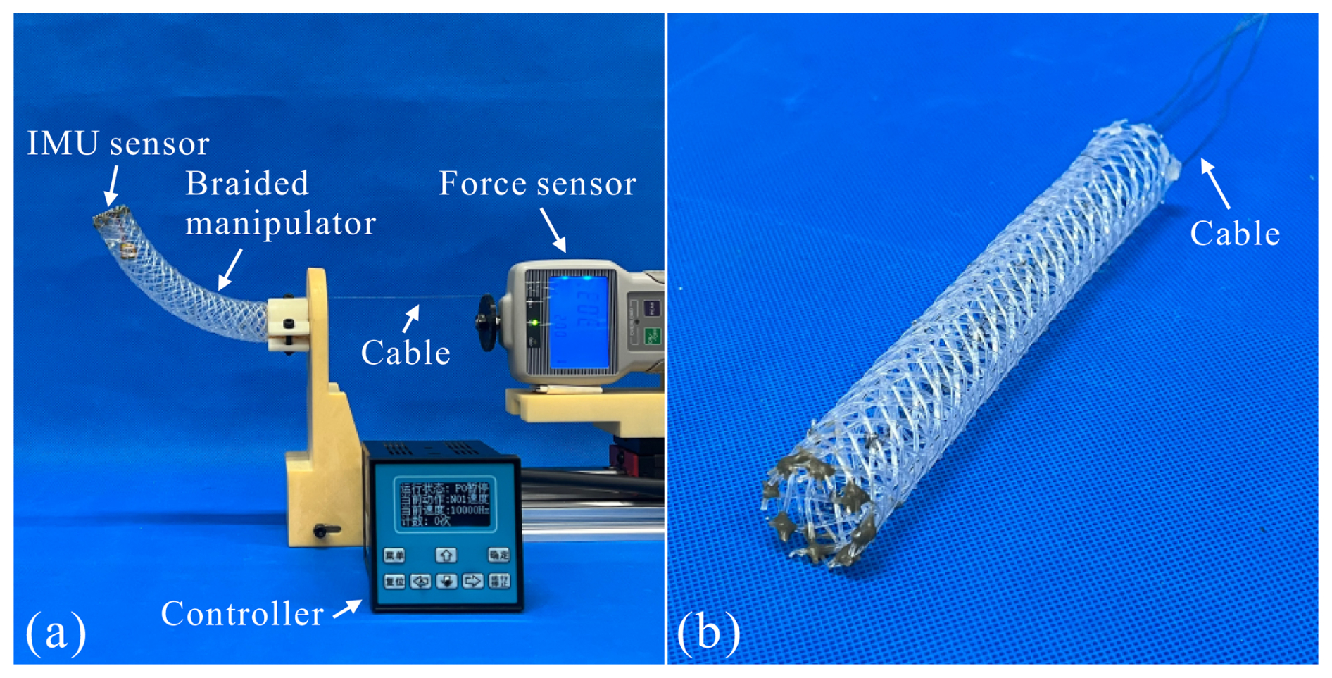
To characterize the kinematical behaviors of the braided manipulator, cable actuation tests were carried out, and the experimental setup is presented in Fig. 3a. The base end of the manipulator was installed onto a fixed platform, while its tip end could move freely in the three-dimensional space. A braided rope was utilized as the actuation cable. One end of the cable was tied to the tip end of the manipulator to exert actuation force. The other end was fixed onto a sliding block, which was actuated by a screw mechanism at a loading speed of 6 mm min−. In addition, an inertial measurement unit (IMU) sensor was installed at the tip end of the manipulator to detect the bending angle. Both the actuation displacement of the cable and the bending angle of the manipulator were recorded during the tests.
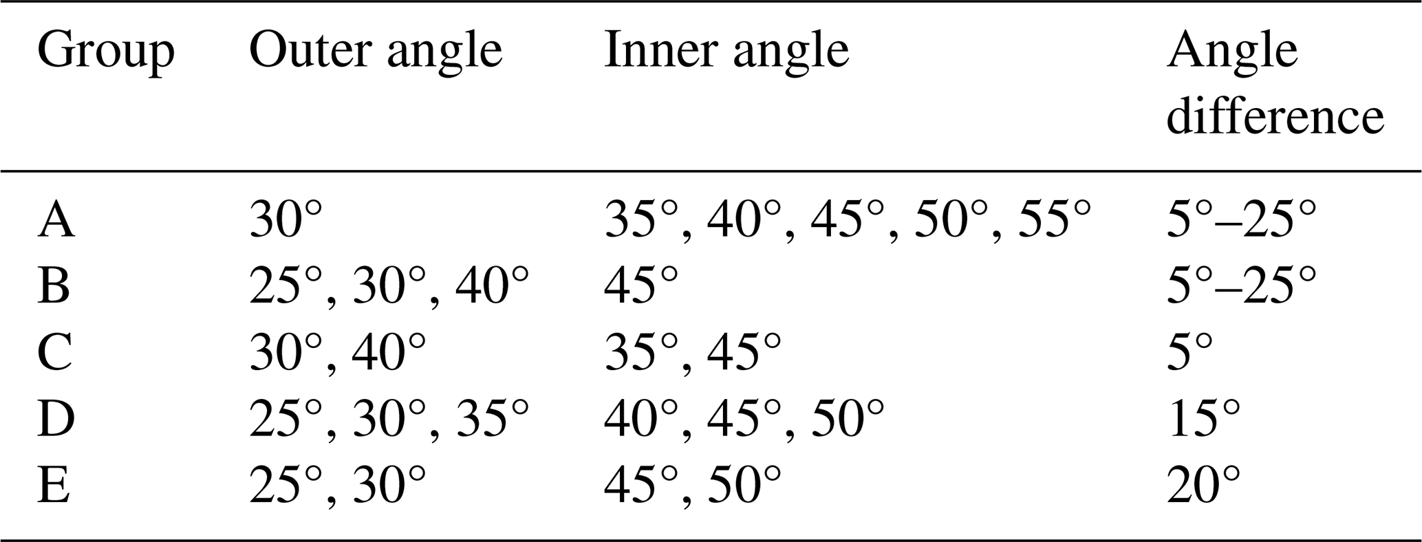
To carry out the parametric analysis of the skeleton, skeleton specimens at various parameters were fabricated. One specimen example is shown in Fig. 3b. Nylon PA66 was selected as the braiding fiber material due to its liner elasticity within a strain of 1.6 %, and the fiber number for each braid layer was set to 16. Lengths and outer diameters of all the specimens were, respectively, 132 and 24 mm, which considers length and diameter requirements of the MIS surgical devices. Fiber diameters of the outer and inner layers were 0.7 and 1.0 mm, respectively. The specimens were divided into three groups according to the varied braiding angles as listed in Table 1.
3.2 Experimental results
3.2.1 Effects of inner braiding angle
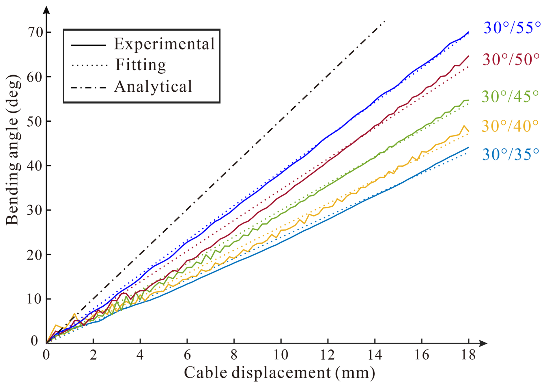
The experimental configurations are firstly shown in Fig. 3a. It can be seen that under the actuation of one cable, the braided manipulator presents a constant-curvature bending deformation, and no obvious profile collapse occurs. This validates the usefulness of the dual-layer braiding pattern in the manipulator design. The limit cable tension loss and the uniform mechanical behavior of the skeleton both contribute to the constant curvature. Figure 4 shows average cable displacement versus bending angle curves at various inner braiding angles. Tests for each physical model were conducted three times and show great consistency. Despite slight fluctuations which may arise from the accuracy drop of the sensor, the bending angle increases with the tensile displacement of the cable in a linear manner for all five curves. This linear response behavior is owing to the constant-curvature bending deformation, which gives a linear relationship between the bending angle and side length shortening according to deflection equations in material mechanics. Liner fittings were carried out towards the curves, and the fitting results are plotted as dashed lines in the figure. The fitting curves match well with the experimental ones, whose minimum R2 among all results still exceeds 0.99. This linear behavior is beneficial to simplifying the kinematical modeling and improving motion accuracy. In addition, the relationship between the bending angle and the cable displacement based on the pure bending assumption is also shown in the figure and is theoretically calculated as
where γ is the bending angle and l is the cable displacement. It is noticed that for a manipulator specimen with a larger inner braiding angle, its bending angle is also larger in comparison, presenting a higher slope of the actuation responsive curve. This is owing to the fact that although the manipulator profile is stable, the structure is still not incompressible. The braided fibers are loosely in contact instead of being welded together. The fibers' deformation allows for a slight shortening in length, making the neutral layer move from the geometric center to the outer side of the arc bending configuration. This enlarges the distance of the cable to the neutral layer, making the curve not as slant as the theoretical result obtained under the pure bending condition. At a larger inner braiding angle, its serious expanding tendency increases the interactions between the two layers, making the manipulator skeleton behave more like an incompressible structure and increase the curve slope.
3.2.2 Effects of outer braiding angle
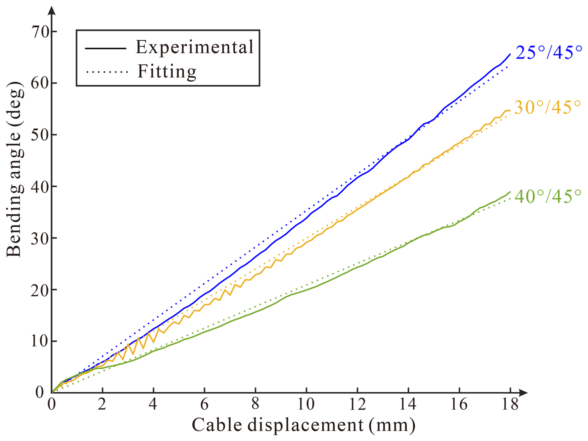
Next, the effects of the outer braiding angle are focused on. Three specimens in Group B with varying outer angles from 25 to 40° were analyzed, and the results are presented in Fig. 5. It can be seen that in all three curves, the bending angles increase linearly with the cable displacement too. At the same cable displacement, the bending angles of the three specimens decrease with the outer braiding angles. The maximum bending angles for specimens with outer braiding angles of 25, 30, and 40° are 65.7, 54.7, and 39.0°, respectively. This is owing to the fact that at a smaller outer braiding angle, its less radial expansion tendency can restrict the inner layer's deformation much more efficiently, which thus improves its resistance to axial compression. The curve slopes of and specimens are, respectively, 3.53 and 3.46, validating a similar efficiency of the inner and outer braiding angles in restricting radial expansion.
3.2.3 Effects of angle differences of the two braid layers
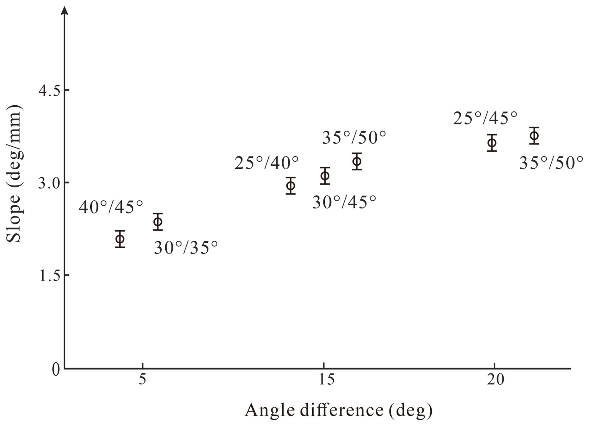
The kinematical response behaviors at both varied inner and outer angles are analyzed by the specimens in Groups C, D, and E, whose angle differences of the two braid layers are 5, 15, and 20°, respectively. Their kinematical response curves are also linear and their slopes are obtained through linear fittings and plotted in Fig. 6. It is found that at the same angle difference, the slopes of different specimens are nearly the same. The maximum slope errors at angle differences of 5, 15, and 20° are, respectively, 0.3, 0.35, and 0.07° mm−1, indicating a similar radial-expansion-restricting performance. In addition, there is a clear trend which shows that the slope increases with the angle difference.
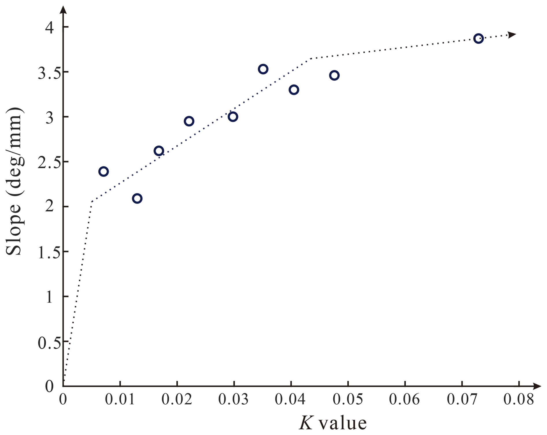
Instead, parameter K defined in this paper can also express the expansion tendency of the two braid layers. Its relationship with the kinematical response curve slope is analyzed and plotted in Fig. 7. When parameter K is in the range of 0.01 to 0.04, a steady increase in slope with parameter K is witnessed. However, when parameter K is over 0.04, the increase in the slope is not as obvious as before. This means that despite a more efficient expansion-restricting function, the braided tube cannot behave like an incompressible structure which leaves its neutral layer in the profile center. In contrast, if parameter K is below 0.01, the outer layer cannot restrict inner layer's expansion well. This causes a nonconstant-curvature bending deformation, which is not applicable to manipulator application. It can be concluded that the fiber orientation, i.e., the braiding angle, plays a vital role in the kinematical response of the braided manipulator. The angle difference of the two layers should be over 5° at least, and an ideal value can be roughly designed referring to the dotted line in Fig. 7.
4.1 Numerical modeling and deformation analysis
Braided skeletons with braiding angles of and were numerically modeled using Abaqus. The modeling strategy introduced in Shang et al. (2019) was adopted. The numerical model is shown in Fig. 8a, in which geometric paths of the braiding fibers were generated following their trajectory equations introduced by Alpyildiz (2012). In addition, a straight line was drawn directly in Abaqus to represent the actuation cable. The braided tube and the cable were modeled using beam elements and truss elements, respectively. Both the tip and base ends of the braided tube were respectively tied to reference points, enabling the definition of boundary conditions, which were consistent with those in experimental tests. The dynamic–explicit step was adopted, which can consider the fiber sliding during a large bending deformation and detect surface contact efficiently. Convergence tests were conducted prior to the analysis, which found that mesh size of 0.25 mm, and step time of 0.3 s, yielded satisfactory results.
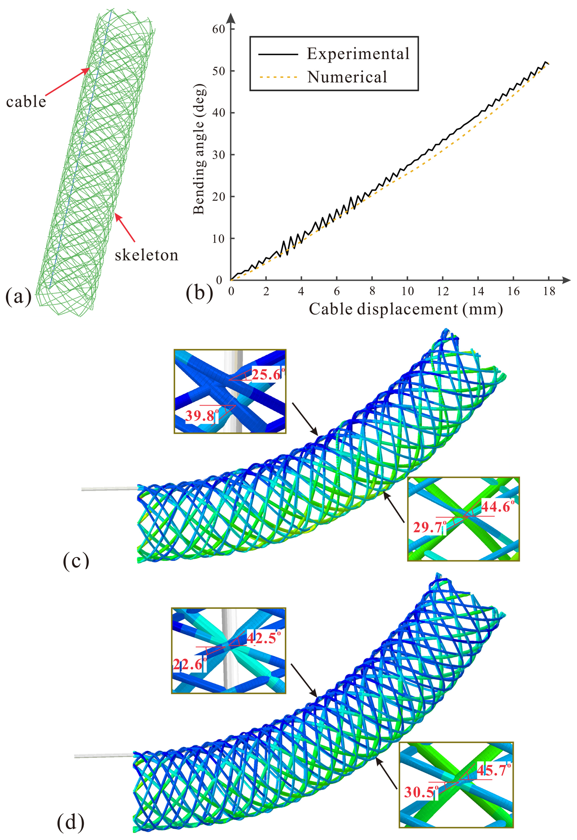
Figure 8Numerical modeling and results: (a) numerical model in Abaqus, (b) cable displacement versus bending angle curves of model , and numerical deformation of models (c) and (d) .
Both experimental and numerical cable displacements versus bending angle curves of the model are shown in Fig. 8b. It finds that the two curves match well, validating the accuracy of the numerical model. Deformation details of the numerical results are then looked into, and the deformation of the numerical skeleton is shown in Fig. 8c, which also presents a constant-curvature bending configuration. The fibers at the inner and outer sides of the arc-deformed configuration are taken out, and their local braiding angles were measured. As shown in Fig. 8c, on the inner side, the inner layer's braiding angle measures to be 25.6°, which is reduced from its initial value of 30°. A similar result is found for the outer layer' angle, whose value drops to 39.8° from its initial value of 45°. According to Eq. (1), a lower local angle value means a shortening in length at the local place. This indicates that the inner side of the skeleton suffers from an axial compression deformation. As for the local deformations at the outer side, the inner and outer braiding angles are, respectively, 44.6 and 29.7°, which are slightly smaller than their initial values. Reductions in braiding angles at both the inner and outer sides of the arc deformation suggest that the structure suffers from a compression deformation during bending.
The numerical deformation of the skeleton together with its local deformation details is shown in Fig. 8d for comparison. It can be seen that the skeleton bends a little more than the skeleton owing to its larger angle difference and thus larger parameter K. The results of local braiding angles indicate that the inner side is still compressed, but what is different from the skeleton is the outer side is tensioned this time. This owing to the bending moment caused by the cable tensile force, which generates tensile force on the outer side. This comparing result indicates a better expansion-restricting function of the outer layer of the specimen. However, the inner braiding angle on the outer side increases by 0.7°, which is not enough to compensate the angle reduction on the inner side (−2.5°). It indicates that the structure is still compressible, and the axial compression moves the neutral layer to the outer side instead of remaining at the geometric center. This enlarged distance between the cable and the neutral layer reduces the overall bending angle at the same cable displacement, explaining the kinematical response of the braided manipulator skeleton in experiments well.
4.2 Parametric analysis
Based on the numerical modeling method, effects of other braiding parameters, such as the fiber number and fiber diameter of the outer skeleton and the fiber's Young's modulus, on the kinematical performance of the braided manipulator are analyzed here. A series of numerical models were established, whose varying parameters are listed in Table 2. The other parameters are the same as those of the numerical model in Sect. 4.1. For each numerical model, the bending angle at a cable displacement of 18 mm was recorded and plotted in Fig. 9.
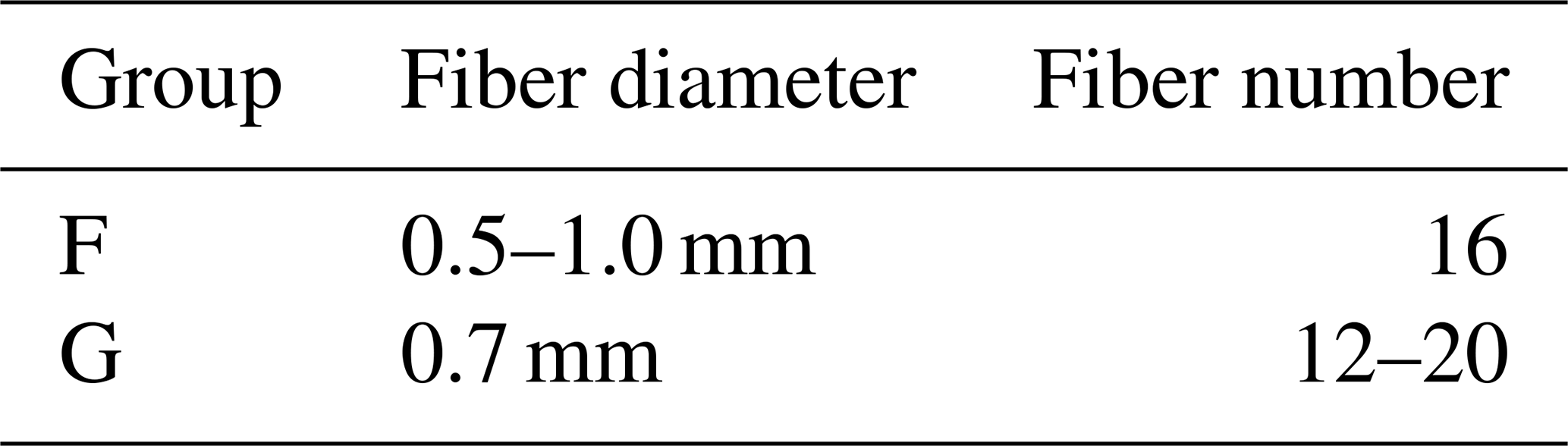
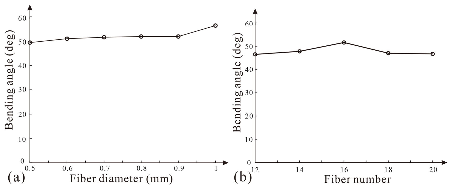
Figure 9Bending angles at cable displacements of 18 mm at various (a) fiber diameters and (b) fiber numbers.
Firstly, effects of the fiber diameter are studied with models in Group F. As shown in Fig. 9a, the bending angles increase slightly with the fiber diameters, and they are 49.4 and 56.4° at a fiber diameter of 0.5 and 1.0 mm, respectively. The bending stiffness of a fiber can be expressed as , which has a linear correlation with d4. Obviously, a larger fiber diameter can contribute to a higher stiffness of the outer layer. It reduces local deformation under the expansion of the inner braided layer, thus improving the expansion-restricting performance and achieving a larger bending angle. However, the expansion behavior of a braid layer is still dominated by the kinematics, which is more affected by the braiding angle. Consequently, the effect is limited in comparison.
Next, effects of yarn number are looked into with models in Group G which had varying fiber numbers from 12 to 20, and the results are presented in Fig. 9b. There is no obvious relationship between the bending angle and the fiber number. The maximum derivation in braiding angle at fiber numbers of 12, 14, 18, and 20 is merely 1.3°. However, a larger braiding angle is witnessed when the fiber number of the outer layer is 16, which is the same as the number of the inner braid layer.
In this paper, the effect of fiber orientation, i.e., the braiding angle, on the kinematical response behavior of the braided manipulator skeleton is studied. Cable actuation tests have been carried out on skeleton specimens at various braiding angles, all of which present linear response behaviors. It also finds that at the same cable tensile displacement, a smaller outer braiding angle and a larger inner braiding angle can both contribute a large overall bending deformation of the manipulator skeleton. A parameter (K) is also defined to express the restricting capability of the outer braid layer imposed on the inner one, which has been successfully correlated to the kinematical response of the manipulator skeleton. Numerical models are finally established that find that local braiding angles are changed during deformation, which affects the bending response through moving the neutral layer in the radial direction. Parametric analysis is also conducted based on the numerical method to the parameters of the outer braid layer. The findings of this study provide a foundation for an optimized design of braided manipulator skeletons. For future work, a comprehensive mechanical model will be developed to explicitly describe the relationship between the fiber orientation and kinematic response, providing more predictive capabilities for manipulator design. In addition, experimental validation of motion control performance will also be conducted by implementing manipulators with different fiber orientations in closed-loop control systems.
The data that support the findings of this study are available from the corresponding author upon reasonable request.
ZS is the lead author of this paper. XH wrote the draft. LY completed theoretical and numerical analyses. JC and ZZ carried out experiments. ZS checked and revised the paper.
The contact author has declared that none of the authors has any competing interests.
Publisher’s note: Copernicus Publications remains neutral with regard to jurisdictional claims made in the text, published maps, institutional affiliations, or any other geographical representation in this paper. While Copernicus Publications makes every effort to include appropriate place names, the final responsibility lies with the authors.
This work is supported by National Natural Science Foundation of China (grant no. 52405039), Scientific Research Fund of Zhejiang Provincial Education Department (grant no. Y202353019) and National College Student Innovation and Entrepreneurship Training Program (grant no. 202310338075).
This paper was edited by Daniel Condurache and reviewed by two anonymous referees.
Alpyildiz, T.: 3D Geometrical Modelling of Tubular Braids, Text. Res. J., 82, 443–453, https://doi.org/10.1177/0040517511427969, 2012.
Chen, X., Zhang, X., and Huang, Y.: A Review of Soft Manipulator Research, Applications, and Opportunities, J. Field. Robot., 39, 281–311, https://doi.org/10.1002/rob.22051, 2022.
Cianchetti, M., Ranzani, T., and Gerboni, G.: Soft robotics technologies to address shortcomings in today's minimally invasive surgery: the STIFF-FLOP approach, Soft Robot., 1, 122–131, https://doi.org/10.1089/soro.2014.0001, 2014.
Dua, K. S.: History of the Use of Esophageal Stent in Management of Dysphagia and Its Improvement Over the Years, Dysphagia, 32, 39–49, https://doi.org/10.1007/s00455-017-9781-7, 2017.
Gifari, M. W., Naghibi, H., and Stramigioli, S.: A Review on Recent Advances in Soft Surgical Robots for Endoscopic Applications, Int. J. Med. Robot. Comp., 15, e2010, https://doi.org/10.1002/rcs.2010, 2019.
Hassan, T., Cianchetti, M., and Mazzolai, B.: Active-Braid, a Bioinspired Continuum Manipulator, IEEE Rob. Autom. Lett., 2, 2104–2110, https://doi.org/10.1109/LRA.2017.2720842, 2017.
Hopper, R. H., Wallace Grant, J., and Popper, P.: Mechanics of a Hybrid Circular Braid with an Elastic Core, Text. Res. J., 65, 709–722, https://doi.org/10.1177/004051759506501202, 1995.
Kim, J. H., Kang, T. J., and Yu, W. R.: Mechanical Modeling of Self-Expandable Stent Fabricated Using Braiding Technology, J. Biomech., 41, 3202–3212, https://doi.org/10.1016/j.jbiomech.2008.08.005, 2008.
Kim, S. H.: Worm gear efficiency model considering misalignment in electric power steering systems, Mech. Sci., 9, 201–210, https://doi.org/10.5194/ms-9-201-2018, 2018.
Laschi, C., Cianchetti, M., Mazzolai, B., Margheri, L., Follador, M., and Dario, P.: Soft Robot Arm Inspired by the Octopus, Adv. Robotics, 26, 709–727, https://doi.org/10.1163/156855312X626343, 2012.
Li, M., Kang, R., and Geng, S.: Design and Control of a Tendon-Driven Continuum Robot, T. I. Meas. Control, 40, 3263–3272, https://doi.org/10.1177/0142331216685607, 2017.
Liu, D., Liu, X., and Du, J.: A Flexible Magnetic Soft Continuum Robot for Manipulation and Measurement at Microscale, CVIA, 8, 950, https://doi.org/10.15212/CVIA.2023.0067, 2023.
Manfredi, L., Capoccia, E., and Ciuti, G..: A Soft Pneumatic Inchworm Double Balloon (SPID) for Colonoscopy, Sci. Rep., 9, 11109, https://doi.org/10.1038/s41598-019-47320-3, 2019.
Moran, M. E.: Evolution of Robotic Arms, J. Robotic. Surg., 1, 103–111, https://doi.org/10.1007/s11701-006-0002-x, 2007.
Paterna, M., Magnetti Gisolo, S., De Benedictis, C., Muscolo, G. G., and Ferraresi, C.: A passive upper-limb exoskeleton for industrial application based on pneumatic artificial muscles, Mech. Sci., 13, 387–398, https://doi.org/10.5194/ms-13-387-2022, 2022.
Rawal, A., Saraswat, H., and Sibal, A.: Tensile Response of Braided Structures: A Review, Text. Res. J., 85, 2083–2096, https://doi.org/10.1177/0040517515576331, 2015.
Russo, M., Sadati, S. M. H., Dong, X., Mohammad, A., Walker, I. D., and Bergeles, C.: Continuum Robots: An Overview, Adv. Intell. Syst., 5, 2200367, https://doi.org/10.1002/aisy.202200367, 2023.
Sanchez, V., Walsh, C. J., and Wood, R. J.: Textile Technology for Soft Robotic and Autonomous Garments, Adv. Funct. Mater., 31, 2008278, https://doi.org/10.1002/adfm.202008278, 2021.
Shang, Z., Wang, S., and You, Z.: A Hybrid Tubular Braid with Improved Longitudinal Stiffness for Medical Catheter, J. Mech. Med. Biol., 19, 1950003, https://doi.org/10.1142/S0219519419500039, 2019.
Stoy, K., Walker, K., Nielsen, S. A., Ayres, P., Heinrich, M. K., Leon, D. A., and Cheheltan, A.: A large-scale, light-weight, and soft braided robot manipulator with rapid expansion capabilities, 2021 IEEE 4th International Conference on Soft Robotics, IEEE, Yale University, New Haven, CT, USA, 12–16 April 2021, 495–500, https://doi.org/10.1109/RoboSoft51838.2021.9479230, 2021.
Wang, H., Wang, C., and Chen, W.: Three-Dimensional Dynamics for Cable-Driven Soft Manipulator, IEEE-ASME. T. Mech., 22, 18–28, https://doi.org/10.1109/TMECH.2016.2606547, 2016.
Wang, P., Tang, Z., and Xin, W.: Design and Experimental Characterization of a Push-Pull Fexible Rod-Driven Soft-Bodied Robot, IEEE Rob. Autom. Lett., 7, 8933–8940, https://doi.org/10.1109/LRA.2022.3189435, 2022.
Yang, H., Xu, M., and Li, W.: Design and Implementation of a Soft Robotic Arm Driven by SMA Coils, IEEE T. Ind. Electron., 66, 6108–6116, https://doi.org/10.1109/TIE.2018.2872005, 2018.
Zhang, J., Fang, Q., and Xiang, P.: A Survey on Design, Actuation, Modeling, and Control of Continuum Robot, Cyborg. Bionic. Syst., 2022, 9754697, https://doi.org/10.34133/2022/9754697, 2022.