the Creative Commons Attribution 4.0 License.
the Creative Commons Attribution 4.0 License.
 | 02 Jul 2025
Design and tests of a planetary non-circular gear train transplanting mechanism for flower plug seedlings
Bingliang Ye
Xiwei Wang
Tao Tang
Gongjun Zeng
Yang Zheng
To address the problems relating to the low efficiency and high labor intensity of the manual operations required for transplanting potted flower plug seedlings in China, along with the lack of suitable transplanting machinery, an automatic bowl-clamping-type transplanting mechanism with a planetary gear train based on incomplete non-circular gear transmission is proposed. The mechanism design method, combining forward parameter modification (to guide optimization design) and reverse design, is applied to design the transplanting mechanism. The kinematic model and parameter modification guiding the optimization design model of the transplanting mechanism are established, and the parametric guidance optimization software is developed. The reverse design model of the transplanting mechanism is established, and the static trajectory of the return section obtained from the optimization design is fine-tuned and fitted with a cubic B-spline curve. The virtual motion simulation analysis of the transplanting mechanism is carried out to verify the correctness of the mechanism design. Transplanting tests demonstrated that the mechanism meets the requirements for transplanting flower plug seedlings, exhibiting good application feasibility.
- Article
(3750 KB) - Full-text XML
- BibTeX
- EndNote


With the rapid growth of the economy and the progress of science and technology in the world, people's high requirements with regard to the ecological environment and quality of life continue to promote the development of the flower industry. According to the data provided by the China General Administration of Customs, China's flower trade volume in terms of imports and exports was USD 720 million in 2022, and the total trade volume of China's flowers maintained a growth trend from 2018 to 2022 (Dong, 2023). Therefore, it is of great scientific significance and application value to strengthen the research into flower plug seedling transplanting mechanisms, promoting the research and development of flower seedling transplanting machinery and the development of the flower industry.
At present, domestic and foreign researchers have done a lot of research work on transplanting technology and equipment for flower plug seedlings (Ji et al., 2023). The PC-16 flower transplanter developed by Visser Company in the Netherlands uses a belt driver to control the movement of the mechanical claw, controlling the opening and closing of the mechanical claws through the cylinder. Its working efficiency can reach up to 4000 plants per hour, but the machine needs to be equipped with a specific flowerpot-conveying device, and the versatility is insufficient (Gu et al., 2012). The RW32 flower automatic transplanting machine developed by Urbinati in Italy uses radio motor drive technology to control the opening and closing of the seedling claws and has a high degree of mechatronics (Zheng, 2022; Liu et al., 2023). Nevertheless, the machine is relatively large in size, which limits its practicality for small-scale or more cost-sensitive applications. In general, the flower plug seedling transplanting machine generally adopts an electromechanical or pneumatic system, and the transplanting efficiency is really high, but the whole machine structure is complex, and the price is relatively expensive; thus, it is difficult to popularize and apply it in the Chinese flower industry. In recent years, China has also developed some prototypes of flower seedling transplanting machines. Feng et al. (2012) developed an automatic flower transplanter based on machine vision. The mechanical claw is opened and closed by the cylinder with a spring to achieve flexible clamping. The machine integrates seedling identification and planting, seedling tray positioning, and other functions. However, due to leaf obstruction, the recognition success rate is relatively low, and there is also the issue of the seedling claw inadvertently lifting the seedling out of the soil after planting. As a result, it has not been widely adopted for large-scale use. Zhou et al. (2018) designed an automatic transplanting mechanism with an elliptical gear planetary gear train for flower plug seedlings, which can realize the transplanting trajectory of a double-pointed-mouth shape. However, the transplanting arm collides with the flowerpot during the transplanting process, resulting in a low success rate in terms of seedling transplanting. Sun et al. (2022) developed a systematic approach for designing diversified seedling transplanting mechanisms using planetary gear trains, overcoming the limitations of single-planet-carrier mechanisms in achieving varied transplanting trajectories. Zhao et al. (2020) designed a 2-DOF (degrees of freedom) five-bar mechanism for flower seedling transplanting, focusing on optimizing the motion and control systems. The design enhanced transplanting accuracy and automation through improved coordination of actuators and end-effector control.
In summary, to address the problems related to the complex structure, high cost, and/or low transplanting efficiency and success rate of flower plug seedling transplanting mechanisms at home and abroad, this paper proposes a planetary gear train transplanting mechanism based on incomplete non-circular gear transmission according to the requirements of flower seedling transplanting. The design method, combining forward parameter modification (guiding optimization design) and local-trajectory fine-tuned reverse design, is used to realize the parameter design of the transplanting mechanisms; virtual-simulation, kinematic, and flower plug seedling transplanting tests are conducted for the mechanism, providing a theoretical and experimental basis for the research into and development of flower plug seedling transplanting machines.
The flower plug seedling transplanting mechanism should complete the four continuous actions of seedling picking, seedling conveying, seedling pushing (seedling planting), and return in one working cycle. The flower plug seedlings are extracted from the plug tray by the transplanting arm of the mechanism and then are transported to the seedling-pushing position and pushed into the flowerpot, completing the transplanting operation.
In order for the transplanting mechanism to achieve the above-mentioned workflow, the following design requirements are proposed:
-
The distance from the seedling pick-up point D to the surface of the plug tray should be two-thirds to three-quarters of the tray height, ensuring that only one flower seedling tray is picked at a time.
-
The system should be able to successfully pick the flower seedlings while avoiding damage to the seedlings' stems and leaves during the picking process.
-
During the return phase, it should prevent the carriage of seedlings or collision with the flower seedlings.
-
The height of the transplanting static trajectory should be less than 260 mm.
-
The angle difference between the seedling-picking angle and the planting angle of the transplanting arm should be between 25 and 45°, ensuring that the seedlings are planted upright in the soil.
According to the requirements of flower plug seedling transplanting, an automatic bowl-clamping-type transplanting mechanism with a planetary gear train based on incomplete non-circular gear transmission is proposed. The mechanism diagram is shown in Fig. 1. The transplanting mechanism is composed of a planetary gear train and two transplanting arms arranged symmetrically about the rotation center O of the planetary carrier. The sun gear (6) is fixed on the frame through the tooth inlay. The first intermediate non-circular gears (3 and 7) are meshed with it and are coaxially fixed with the second intermediate non-circular gears (2 and 8) to install the rotation centers P and N, respectively, onto the planetary carrier (12). The toothless part of the sun gear (6) is fixed with the concave lock stop arc (5). The first intermediate non-circular gears (3 and 7) are fixedly installed with the convex lock stop arc (4 and 9, respectively). The planetary non-circular gears (1 and 10), whose rotation centers are Q and M, are meshed with the second intermediate non-circular gears (2 and 8, respectively). The transplanting arms (13 and 11) are coaxially fixed with the planetary gears (1 and 10, respectively). The transplanting arm is composed of a cam, a fork, a seedling-pushing rod, and two seedling claws.
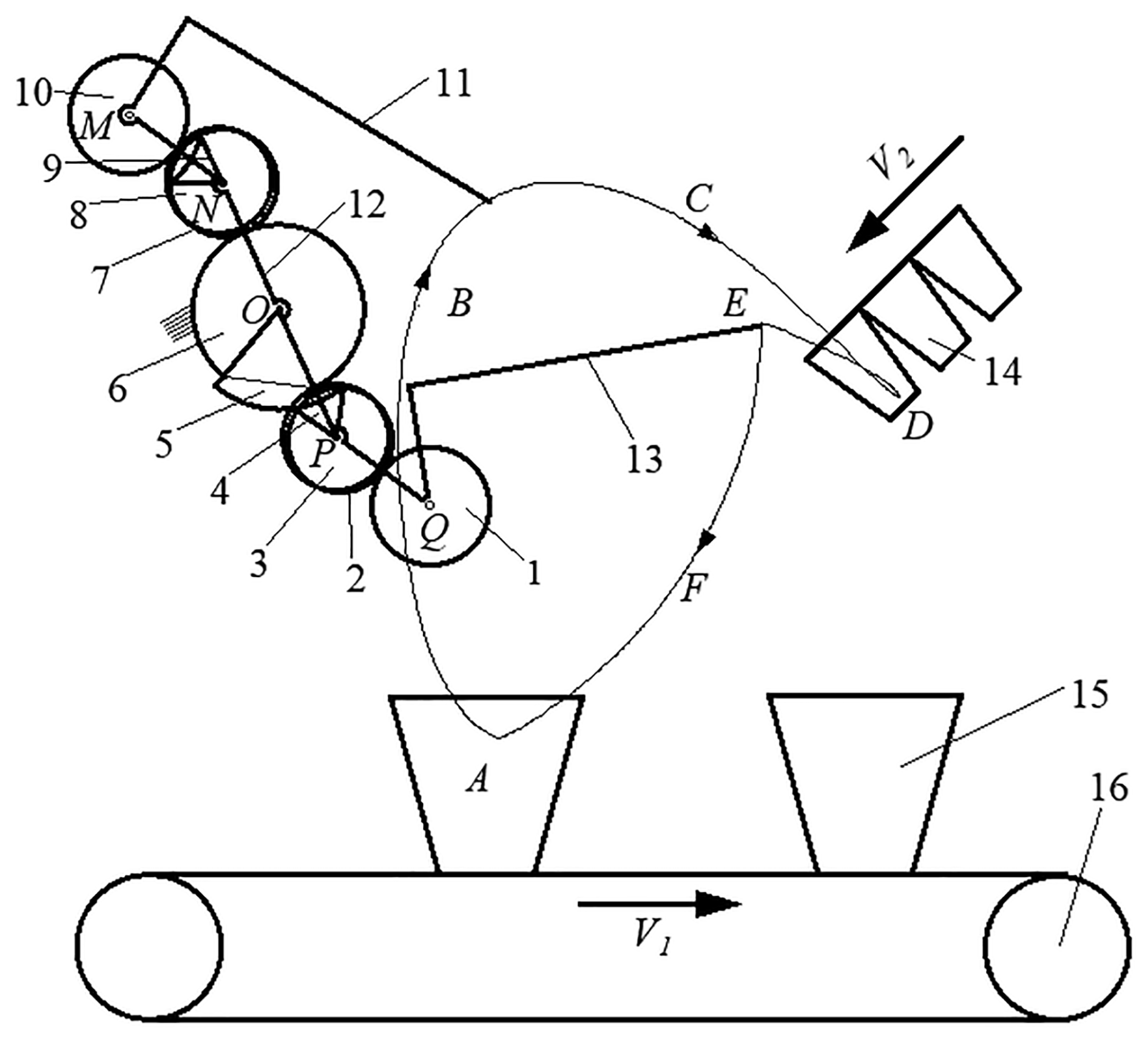
Figure 1Schematic diagram of the transplanting mechanism for flower plug seedlings. The numbers denote the following: 1, 10 – planetary non-circular gear; 2, 8 – second intermediate non-circular gear; 3, 7 – first intermediate non-circular gear; 4, 9 – concave lock stop arc; 5 – convex lock stop arc; 6 – sun gear (incomplete non-circular gear); 12 – planetary carrier; 13, 11 – transplanting arm; 14 – plug tray; 15 – flowerpot; 16 – flowerpot conveyor belt.
When the transplanting mechanism starts to work, the transplanting arms (11 and 13) rotate clockwise around the rotation center O of the planetary carrier (12) and counterclockwise around their own rotation center. Under the joint action of these two movements, the end points of the transplanting arms (11 and 13) form the transplanting trajectory ABCDEF. In the motion trajectory, the CDE section is the seedling-pick-up trajectory, the EF section is the seedling-conveying trajectory, the FA section is the seedling-planting trajectory, and the ABC section is the return trajectory. From the initial installation position, the transplanting arm (13) rotates clockwise. When the convex lock stop arc (5) engages with the concave lock stop arc (4), the end point of the transplanting arm (13) forms the EFA segment trajectory. When the planetary frame continues to rotate and the convex and concave locking arc are separated, the toothed part of the sun gear (6) engages with the first intermediate non-circular gear (3), and the end point of the transplanting arm (13) forms the ABCDE segment trajectory.
The transplanting process mainly consists of two parts: taking seedlings and planting seedlings. When the transplanting mechanism moves to the point D, the claw gradually closes from the mouth of the hole tray, and when it reaches the point D inside the hole tray, the flower seedlings are completely clamped and removed from the hole tray to complete the operation of picking seedlings. At the same time, the synchronous belt performs an intermittent motion, moving the flowerpot (15) to the planting point A. When it reaches the planting point A, the seedling claw quickly opens, and the flower plug seedling is planted in the soil, completing the seedling-planting operation.
The forward parameter modification guiding the optimization design method is applied to solve the complex multi-objective optimization design problem with strong nonlinearity, fuzziness, and coupling of the planetary non-circular gear train transplanting mechanism for flower plug seedlings (Yu et al., 2023b; Zhou et al., 2023b). In this paper, the kinematic modeling of the transplanting mechanism is firstly carried out, and the numerical optimization objectives and constraint equations of the transplanting mechanism are established. The parameter modification guiding the optimization software of the mechanism is developed independently, and a set of optimal parameters of the mechanism satisfying the optimization objectives are obtained by using the parameter modification guiding the optimization method.
3.1 Kinematic model of the transplanting mechanism
The purpose of the kinematic analysis is to establish the kinematic model of the transplanting mechanism, to clarify the motion trajectories and interrelationships of each component, and to provide essential support for the subsequent parameter optimization. This ensures that the optimization goals and constraints accurately reflect the practical transplanting requirements (Yu et al., 2023a).
As shown in Fig. 2, the rectangular coordinate system xoy is established with the rotation center O of the planetary carrier as the coordinate origin. Because the transplanting mechanism is symmetrically arranged about point O, one side of the mechanism is taken and analyzed for kinematic modeling. The right side is the initial installation position of the transplanting mechanism, and the left side is the position of the mechanism after the planetary carrier rotates clockwise by angle φ1.
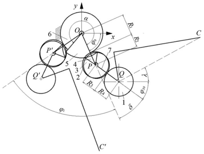
Figure 2Motion diagram of the transplanting mechanism with planetary non-circular gear train. The numbers denote the following: 1 – planetary gear, 2 – second intermediate gear, 3 – first intermediate gear, 4 – concave lock stop arc, 5 – convex lock stop arc, 6 – sun gear, 7 – planetary carrier.
The first-stage transmission of the transplanting mechanism is non-circular gear transmission, and the radius equation of the first intermediate non-circular gear pitch curve is as follows (Wu et al., 2017):
where a, b, c, and d are the coefficients of the gear pitch curve equation. φ2 is the angular displacement of the intermediate gear relative to the planetary carrier.
According to the gear transmission relationship, the angular displacement φ1 of the planetary carrier can be obtained:
where L is the center distance between the sun gear and the first intermediate non-circular gear.
According to the principle of gear meshing, if φ1 is equal to α then φ2 is equal to 2π. α is the central angle corresponding to the toothed part of the sun gear. Through the numerical integration of Eq. (2), L can be obtained, and then the angular displacement φ2 of the intermediate gear can be obtained as follows:
The pitch curve equation of the sun gear is obtained as follows:
The second-stage gear transmission of the transplanting mechanism is elliptical gear transmission, and the pitch curve equation of the second intermediate non-circular gear is as follows (Ye et al., 2016):
where δ is the angle between the sections OP and PQ of the planetary carrier. k is the ratio of the short to the long semi-axis of the elliptical gear. a1 is the length of the long semi-axis of the elliptical gear.
According to the motion transmission relationship of the elliptical gear transmission, the angular displacement of planetary gear can be obtained.
The initial angular displacement of the long semi-axis of the planetary elliptical gear relative to the planetary carrier is obtained as follows:
The static trajectory curve equation of the seedling claw tip C of the transplanting arm is as follows:
where φ0 is the installation angle of the planetary carrier at the initial installation position of the mechanism. λ is the angle between the line connecting the rotation center of the planetary gear and the seedling claw tip and the long axis of the planetary elliptical gear. S is the distance from the rotation center of the planetary elliptical gear to the seedling claw tip.
According to the operation law of the transplanting machine, when the transplanting mechanism rotates for one cycle, the transplanting operation is performed twice, and the flowerpot conveyor belt advances by two plant spacings 2H. The dynamic trajectory curve equation of the transplanting-arm seedling claw tip C' is as follows:
where H is the distance between flowerpots on the conveyor belt.
3.2 Parameter modification guiding the optimization design objectives and constraint equations for transplanting mechanism
According to the design requirements of flower plug seedling transplanting mechanisms, the numerical objective functions of the transplanting mechanism are established based on the aspects of the motion posture of the transplanting arm and the depth of seedling pick-up. Then, according to the fuzzy characteristics of the transplanting-mechanism optimization problem, the membership function of fuzzy mathematics theory is used to describe each objective function. At the same time, according to the requirement of no motion interference during the transplanting operation of the mechanism, the constraint equations of the parameter optimization of the mechanism are derived. Subsequently, the optimization design model of the transplanting mechanism is established, which takes the maximum sum of the membership degree of each objective function as the optimization objective and includes the constraint equations (Zhou et al., 2023a; Ye et al., 2024).
3.2.1 Numerical objectives
(1) In order to reduce the injury of seedlings and to ensure the upright degree of seedlings, the acute angle between the transplanting arm and the horizontal plane (i.e., the seedling-pick-up angle and the seedling-planting angle) should meet the corresponding requirements when the transplanting mechanism extracts and plants seedlings (Yu et al., 2019). As shown in Fig. 3, the coordinates of the seedling points B and B′ of the transplanting mechanism are (xB, yB) and (xB′, yB′), respectively. AB and A′B ' are the seedling claw lines at the time of seedling pick-up and seedling planting, respectively. Then the seedling-pick-up angle, the seedling-planting angle, and the angle difference between the two angles are obtained; that is, the first, second, and third objective functions are as follows:
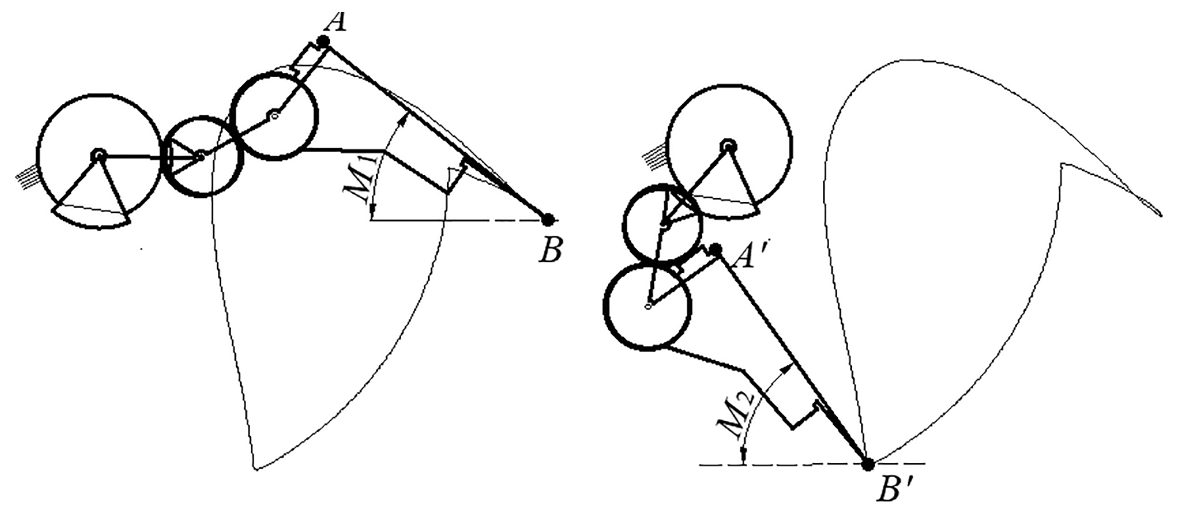
According to the relevant experimental research and expert experience of our research group, the ideal range of the first objective function is determined to be , with an expected value of 30°. The ideal range of the second objective function is , with an expected value of 60°. The ideal range of the third objective function is , with an expected value of 35°.
(2) If the part of the seedling claw entering the seedling tray hole is too short or too long when the transplanting mechanism extracts the seedling, this will lead to the failure of seedling pick-up or cause damage to the root system of the plug seedling and collide with the plug tray; thus, it is necessary to control the depth of the seedling claw entering the plug tray. As shown in Fig. 4, point C of coordinate (xC, yC) is the position of the seedling claw tip at the hole plate, and point D of coordinate (xD, yD) is the seedling-pick-up point of the transplanting mechanism. Then, the seedling claw insertion depth is obtained; that is, the fourth objective function is as follows:
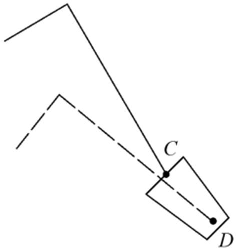
In order to ensure the reliability of seedling pick-up, the ideal range of the fourth objective function is determined to be 33 mm mm, with an expected value of 35 mm.
To improve the reliability of the fuzzy interval, when the amplification coefficient method is used to determine the fuzzy boundary of the target requirements in the membership function, the upper limit and the lower limit of the amplification coefficient are selected to be 1.05 and 0.95, respectively. The objective functions M1∼M4 are described by the symmetric trapezoidal distribution membership function as follows:
where Ei is the expected value of the ith target, and and are, respectively, the lower and upper limits of the ith target as determined by the amplification coefficient method.
3.2.2 Constraint equations
(1) To prevent the interference between the two transplanting arms, the minimum distance between the two transplanting arms needs to be constrained. As shown in Fig. 5, EF is the minimum distance between the two transplanting arms when the transplanting mechanism is at work, and their coordinates are (xE, yE) and (xF, yF), respectively. Then the first constraint equation is as follows:
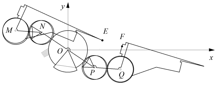
Considering the manufacturing error, assembly error, and motion vibration of the mechanism, the value range of Y1 is determined to be [4, 8 mm].
(2) To prevent the seedling claw from interfering with the plug tray during the seedling-pick-up process, the swing angle range of the seedling claw during the seedling-pick-up process is determined to be [15, 25°].
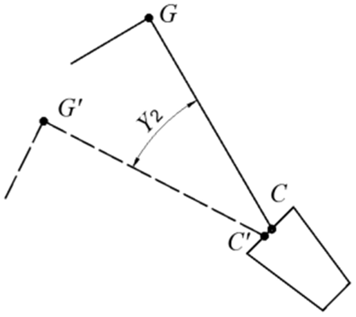
Figure 6Diagram of the swing angle of the seedling claw during the seedling-pick-up process.
As shown in Fig. 6, CG is the position of the seedling claw just entering the seedling tray hole, and the coordinates of points C and G are (xC, yC) and (xG, yG), respectively. is the position of the seedling claw just leaving the seedling tray hole, and the coordinates of points C′ and G′are (, ) and (, ), respectively. Then the second constraint equation is obtained.
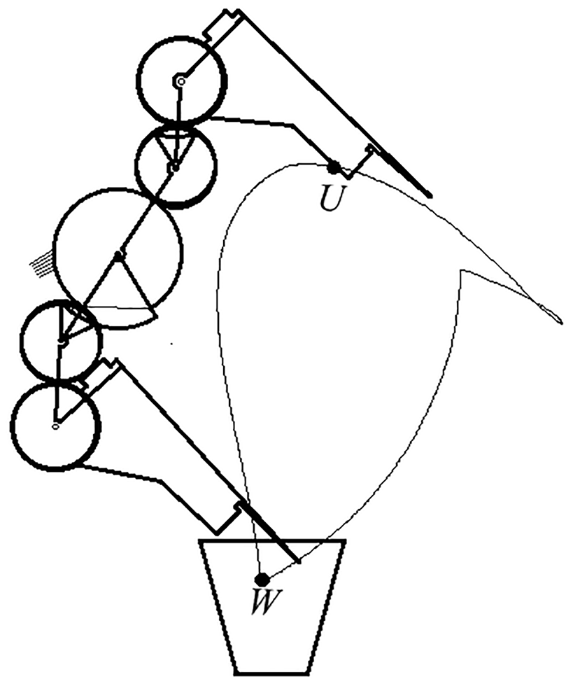
(3) To prevent the seedling claw from interfering with the flowerpot during the seedling-planting process, considering the installation position of the mechanism, the seedling-planting method, the size of the flowerpot, and the compactness of the mechanism, the height range of the transplanting trajectory is determined to be [230, 250 mm]. As shown in Fig. 7, the set the coordinates of the highest point U in the transplanting trajectory are (xU, yU), and the coordinates of the lowest point W are (xW, yW). Then the third constraint equation is obtained.
(4) To ensure that the cusp of the concave locking arc does not interfere with the side of the convex locking arc when entering and separating the engagement, it is necessary to constrain its structure. As shown in Fig. 8, point H is the cusp of the concave locking arc, and its coordinate is (xH, yH). Point G is the cusp of the convex locking arc, and its coordinate is (xG, yG). OG is the side of the convex locking arc. Then the fourth constraint equation is obtained.
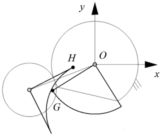
Figure 8Diagram of the relative position relationship of the concave and convex locking arcs.
Considering the dynamic load of the gear transmission and the mechanism compactness, the value range of Y4 is determined to be [2, 4 mm].
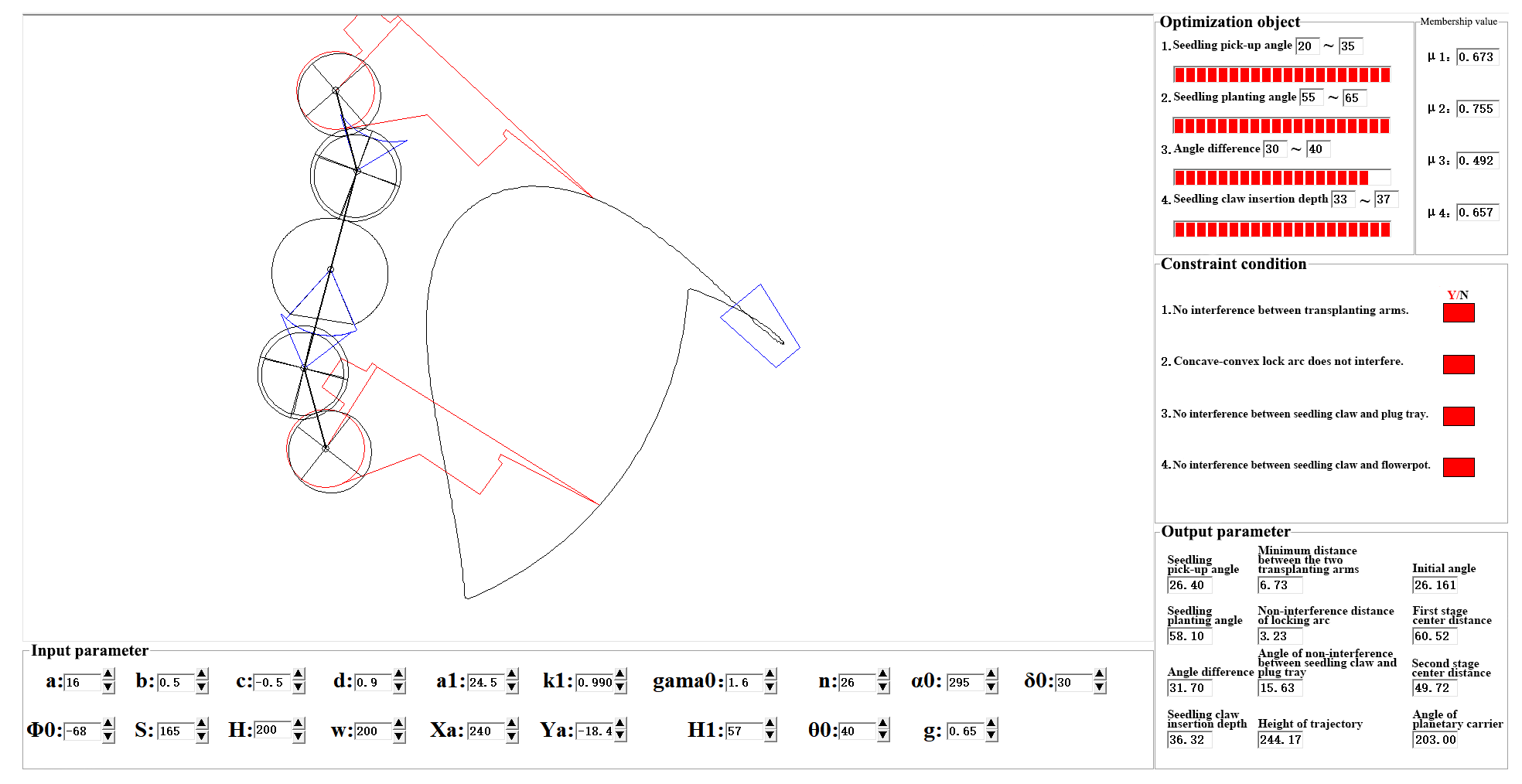
Figure 9Main interface of forward parameter modification guiding the optimization design software.
3.3 Optimization results and analysis of the transplanting mechanism
The parameter modification guiding the optimization design software is independently developed based on the Visual Basic6.0 platform, and the main interface of the software is shown in Fig. 9. A total of 11 main parameters affecting the transplanting trajectory – a, b, c, d, a1, k, λ, α, δ, φ0, and S – are taken as the optimization design variables of the mechanism. By using the software, the motion simulation and automatic optimization parameters of the mechanism are carried out after inputting the initial values of the parameters. The membership values of the optimization objectives under the optimized parameters are expressed by the progress bar. When the sum of the progress bars is the largest and the mechanism parameters conform to the constraint equations, the multi-objective optimization of the mechanism is completed. The software can automatically solve the problem, greatly improving efficiency compared to manual parameter adjustments.
Based on an analysis of the influence law of each parameter in relation to the transplanting trajectory of the mechanism, a set of optimal parameters meeting the optimization objectives are obtained: a=16, b=0.5, , d=0.9, a1=24.5 mm, k=0.99, λ=26°, α295°, δ=30°, , and S=165 mm. The static trajectory and dynamic trajectory of the optimized mechanism are shown in Fig. 10, and the trajectory with a single-pointed-mouth shape meets the posture requirements of seedling claws during seedling pick-up and seedling planting. The seedling-pick-up angle, the seedling-planting angle, and their difference are 26.40, 58.10, and 31.70°, respectively. The insertion depth is 36.32 mm during the seedling-pick-up operation, and the transplanting trajectory height of the mechanism is 244.17 mm. Furthermore, the motion simulation of the flower transplanting mechanism can be observed through the graphic display area of the software. During the whole transplanting process, there is no interference between the two transplanting arms, the seedling claws, and the seedling tray. Based on the results, the optimized mechanism basically meets the requirements for transplanting flower plug seedlings. However, the return section of the dynamic trajectory of the mechanism is a bit forward leaning, and so the planted flower plug seedlings may be brought out or pushed down by the seedling claws, leading to the failure of seedling planting. Therefore, the following reverse design of the transplanting mechanism will be conducted to solve this problem and to ensure the success rate of seedling transplanting.
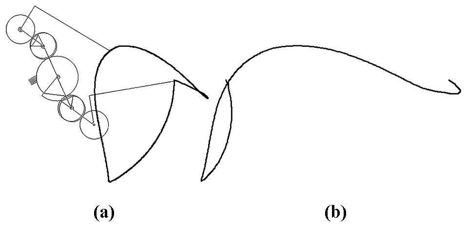
Figure 10Trajectories after parameter modification guiding the optimization design. (a) Static trajectory. (b) Dynamic trajectory.
In this paper, based on the shortcoming analysis of the motion trajectory obtained from the forward design, the return section trajectory is optimized and adjusted, and the cubic B-spline curve is used to fit the selected data points. Based on the adjusted trajectory, the reverse kinematic analysis and calculation method of the three-bar model are used to obtain better parameters for the planetary non-circular gear train transplanting mechanism for flower plug seedlings.
4.1 Reverse design model of the transplanting mechanism
Through the trajectory analysis, it is found that the angle between the return section of the static trajectory and the vertical direction is too small and that that of the dynamic trajectory is a bit forward leaning, which may cause the planted flower plug seedlings to be brought out or pushed down by the seedling claws, leading to the failure of seedling planting. In order to improve the success rate of flower plug seedling planting, it is necessary to fine-tune the return section of the static trajectory to increase its angle in relation to the vertical direction, specifically from the 9.27° of the forward design to 29.03°, as shown in Fig. 11.
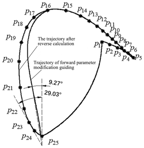
A total of 25 data points are taken in the adjusted static trajectory, and the cubic B-spline curve is used to fit the curve including data points p1∼p25, and the coordinates of each trajectory data point in a period are obtained.
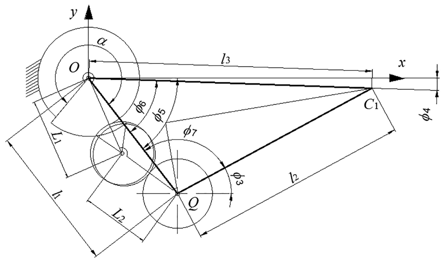
As shown in Fig. 12, the rectangular coordinate system xoy is established by taking the rotation center O of the planetary carrier as the coordinate origin, where point C1 is the cusp of the seedling claw, and point Q is the rotation center of the planetary gear. The lengths of OQ, QC1, and OC1 are set as l1, l2, and l3, respectively. ϕ4, ϕ5, ϕ6, and ϕ7 denote the angular displacement of OC1, OQ, and OQ relative to QC1 and of QC1 relative to OQ, respectively. The following equations can be obtained according to the motion law of the rod:
where xC1 and yC1 are the coordinates of selected data points in the trajectory.
According to the trigonometric function relationship between three rods, ϕ6 and ϕ7 for one period can be obtained, and the initial total transmission ratio of the mechanism is calculated as follows:
The pitch curve radius of the planetary gear of the transplanting mechanism is constructed as follows:
where L22 is the initial value of the center distance of the second-stage gear transmission of the mechanism.
According to the principle of gear meshing, the following equation can be obtained because, in one period, the rotation angle of the second intermediate gear relative to the planetary carrier should be equal to that of the planetary gear:
where ϕ2 is the rotation angle of the second intermediate gear relative to the planetary carrier.
The initial value of the center distance L22 of the second-stage gear transmission is given. According to Eq. (22), the exact value L2 of the center distance of the second stage is obtained by means of an iterative method, and then the pitch curve radius of the second intermediate gear is calculated as follows:
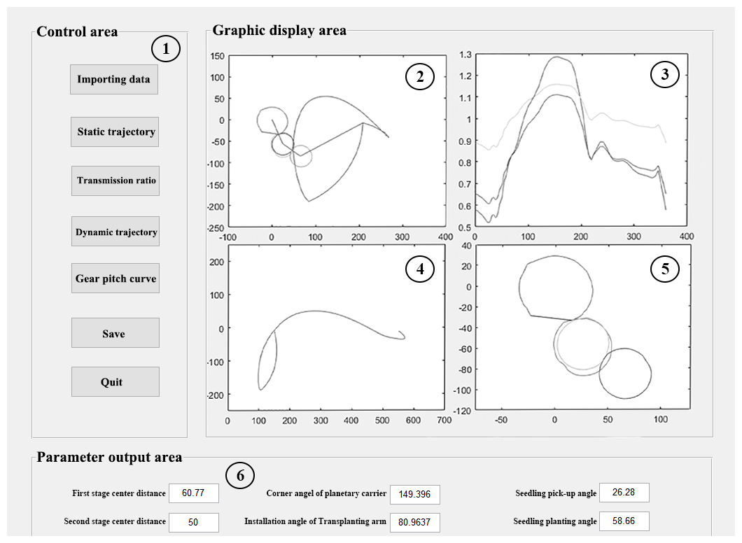
Figure 13Main interface of the reverse design software. Numbers denote the following: 1 – control area, 2 – static trajectory, 3 – transmission ratio curve, 4 – dynamic trajectory, 5 – pitch curves of gears, 6 – parameter output area.
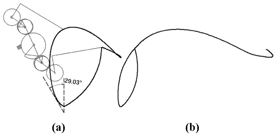
Figure 14Trajectory of reverse design of the mechanism. (a) Static trajectory. (b) Dynamic trajectory.
According to the gear transmission relationship, the pitch curve radius of the first intermediate non-circular gear is calculated using the following equation:
where L11 is the initial value of the center distance of the second-stage transmission.
According to the principle of gear meshing, when the first intermediate gear rotates for one cycle, its rotation angle should be equal to the central angle corresponding to the toothed part of the sun gear; then the following equation is obtained:
where ϕ1 is the rotation angle of the planetary carrier. α is the central angle corresponding to the toothed part of the sun gear.
Given the initial value of the center distance L11 of the first-stage transmission, the exact value L1 of the first-stage center distance is obtained using the iterative method according to Eq. (25), and the pitch curve radius of the sun gear is obtained as follows:
The static and dynamic trajectory curve equations of the seedling claw cusp C1 and of the transplanting arm are as follows:
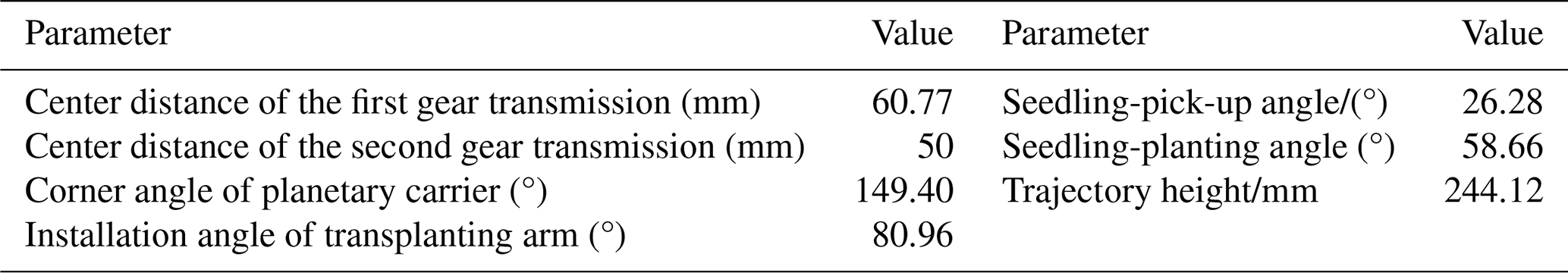
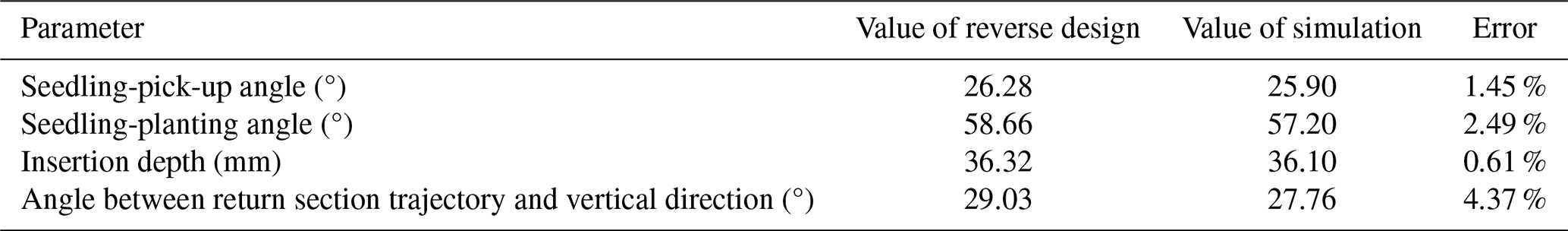
Table 2Comparison of the parameters of virtual simulation and reverse design for the mechanism.
4.2 Reverse design results and analysis of the transplanting mechanism
Based on the MATLAB platform, the reverse design software for the flower plug seedling transplanting mechanism is developed independently, as shown in Fig. 13. After the coordinate data of 25 data points are input into the software, its main interface can, intuitively and in real time, display the parameters, motion trajectory, and pitch curves of the non-circular gears of the transplanting mechanism after reverse design.
The dynamic and static trajectories obtained from reverse design of the transplanting mechanism are shown in Fig. 14. The mechanism parameters after the reverse design are shown in Table 1. Through analysis and comparison, it can be seen that, except for the return section trajectory, the other section trajectories are basically consistent with those of the forward parameter modification guiding the optimization design. The angle between the return section of the static trajectory and the vertical direction is increased from 9.27°, as obtained from the parameter modification guiding the optimization design, to 29.03°, as obtained with the reverse design. The seedling-pick-up angle and seeding-planting angle only change a little before and after the reverse design of the mechanism, and the trajectory height is basically the same.
According to the parameters obtained from the reverse design of the planetary non-circular gear train transplanting mechanism for flower plug seedlings, the three-dimensional models of the mechanism are built based on SOLIDWORKS software and are then imported onto the ADAMS platform for conducting virtual-simulation analysis (Li and Chen, 2020), obtaining the static and dynamic trajectories of the transplanting mechanism, as shown in Fig. 15.
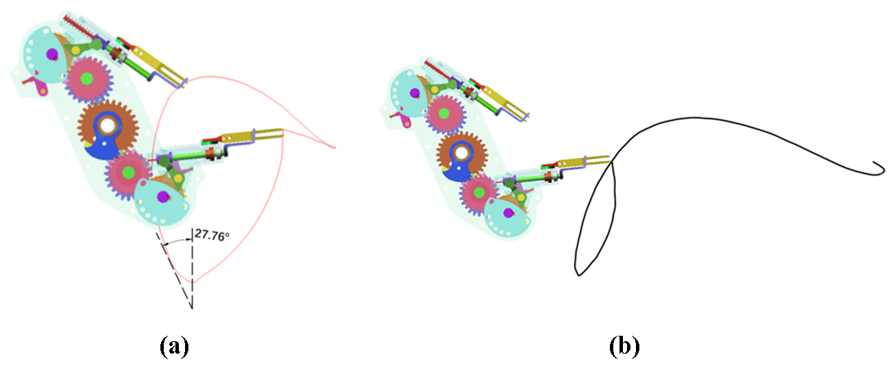
Comparing Figs. 14 and 15, it is found that the virtual-simulation trajectory is basically consistent with the theoretical trajectory of the reverse design. The measurement function of the software is used to measure the angle of the seedling pick-up and planting, the insertion depth, and the angle between the return section trajectory and the vertical direction of the mechanism, which are compared with the theoretical results, as shown in Table 2. It can be seen that the parameters of the virtual simulation are basically consistent with those of the reverse design, which verifies the correctness of the reverse design method and results for the mechanism.
The prototype and test bench of the planetary non-circular gear train transplanting mechanism for flower plug seedlings, as shown in Fig. 16, are developed and manufactured to conduct tests of kinematics and seedling transplanting in the laboratory, testing the kinematic characteristics and success rate of seedling transplanting and verifying the transplanting performance and application feasibility of the transplanting mechanism.
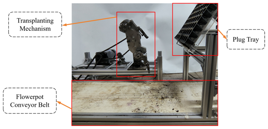
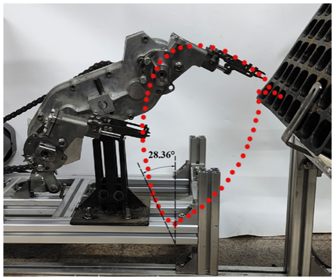
Table 3Parameter comparison of reverse design and kinematic test.
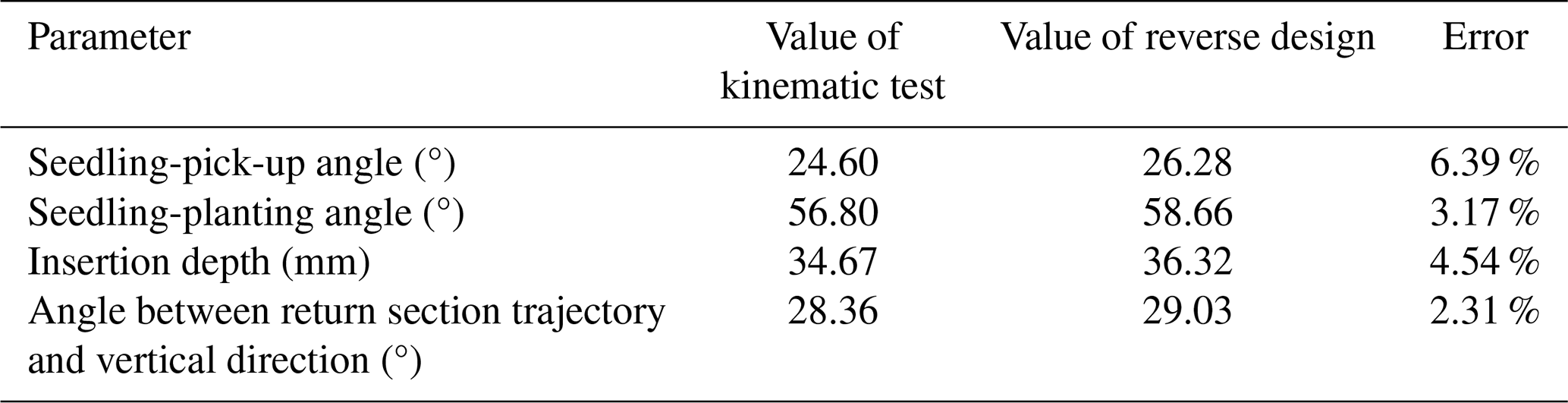
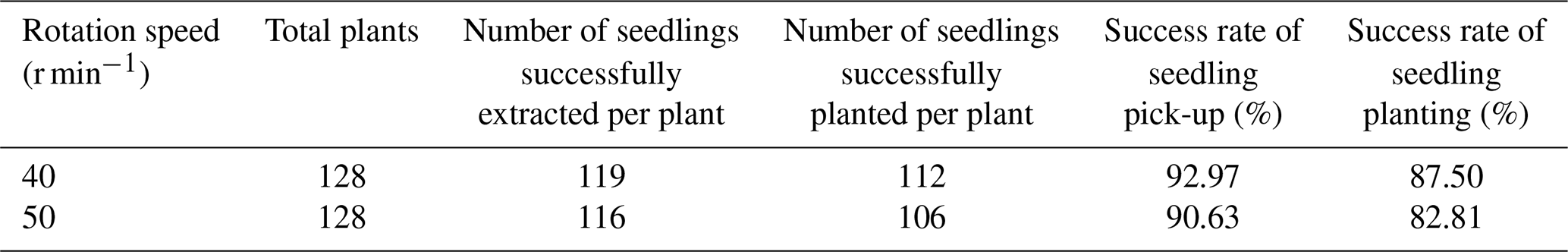
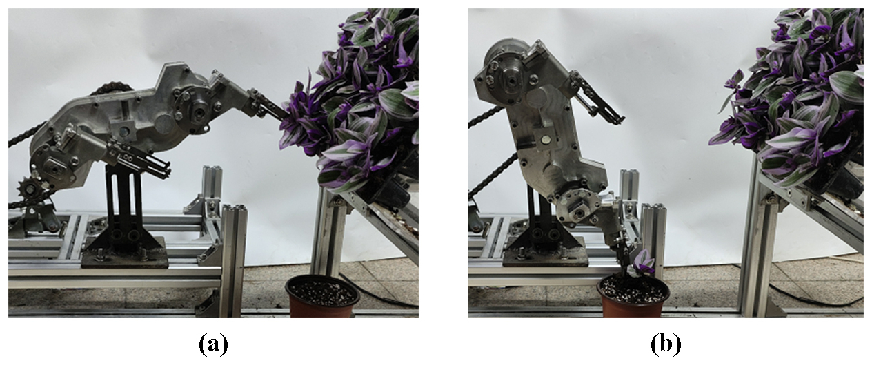
Figure 18Photographs of seedling transplanting tests. (a) Seedling-pick-up operation. (b) Seedling-planting operation.
6.1 Kinematic test of the transplanting mechanism
The camera is used to record the working video with the transplanting mechanism idling, and the video is imported into Adobe premiere software for treatment. The position of the cusp of the seedling transplanting claw in the video is marked with a red dot, and the static trajectory of the cusp of the seedling claw of the transplanting mechanism prototype can be obtained, as shown in Fig. 17.
Comparing Figs. 14 and 17, it can be seen that the static trajectory obtained from the kinematic test of the mechanism prototype is basically consistent with the static trajectory obtained from the reverse design of the mechanism, and the overall coincidence degree is relatively high. The slight difference in the trajectory of the seedling-pick-up section is due to the processing and assembly errors and vibration of the transplanting mechanism.
The seedling-pick-up angle, the seedling-planting angle, the insertion depth, and the angle between the return section trajectory and the vertical direction in the test trajectory are all measured and compared with the theoretical results, as shown in Table 3. Each parameter is basically consistent with that of reverse design, which verifies the correctness of the theoretical model and the design results.
6.2 Flower plug seedling transplanting tests for the mechanism prototype
The transplanting tests for flower plug seedlings are carried out, as shown in Fig. 18. The flower plug seedlings of a bracket plant with a seedling age of about 35 d and an average seedling height of about 70 mm are selected as the test object. The seedling tray is made up of 8×16 holes. The diameters of the top and bottom plane and the height of the flowerpots used for the transplanting tests are 120, 80, and 100 mm, respectively. Two groups of transplanting tests are conducted, with the rotational speeds of the mechanism being 40 and 50 r min−1, respectively, and with 128 plants for transplanting in each group.
The results of the seedling transplanting tests are shown in Table 4. When the rotational speeds of the mechanism are 40 and 50 r min−1, the success rates of seedling planting are 87.50 % and 82.81 %, respectively, and there are no instances where the planted flower plug seedlings are brought out or pushed down by the seedling claws. Furthermore, with the increase in the rotational speed of the mechanism, the success rate of seedling pick-up is slightly reduced, and the success rate of seedling planting is significantly reduced. The transplanting tests show that the transplanting mechanism meets the design requirements and demonstrates good application feasibility. Compared to existing domestic mechanisms, our mechanism exhibits a slightly higher success rate in terms of seedling planting (Zhou et al., 2019).
The main reasons for the failure of seedling transplanting are as follows. First, the excessive vibration of the transplanting mechanism leads to a decrease in the accuracy of seedling pick-up and planting. Second, the vibration of the seedling feeding device leads to insufficient insertion depth of the mechanism during seedling pick-up, resulting in the falling of the seedlings during the seedling-conveying stage.
In this study, according to the agronomic requirements of flower plug seedling transplanting, the design method combining forward parameter modification guiding optimization design and reverse design is applied for designing an automatic bowl-clamping-type transplanting mechanism with a planetary non-circular gear train. The virtual-simulation analysis, kinematic characteristic test, and seedling transplanting test of the transplanting mechanism are conducted in the laboratory. The main conclusions drawn are as follows.
The flower plug seedling transplanting mechanism with a planetary gear train based on incomplete non-circular gear transmission is proposed. The kinematic model and parameter modification optimization design model of the transplanting mechanism are established based on the analysis of the motion and design requirements for the mechanism. By using the parameter modification guiding the optimization design method, a set of mechanism parameters basically meeting the transplanting requirements for flower plug seedlings are obtained.
Based on the shortcoming analysis of the transplanting trajectory obtained from the forward parameter modification guiding the optimization design for the transplanting mechanism, the reverse design method of the local return section trajectory fine-tuned for the mechanism is proposed. The reverse design model of the mechanism is established. Through the reverse design for the mechanism, the angle between the return section of the static trajectory and the vertical direction increased obviously, which solves the problem of the planted flower plug seedlings being brought out or pushed down by the seedling claws.
The motion trajectory, the seedling-pick-up angle, the seedling-planting angle, and the angle between the return section of the static trajectory and the vertical direction obtained through virtual-simulation and kinematic tests of the mechanism are basically consistent with those from the reverse design for the mechanism, showing the correctness of the theoretical model and results for the mechanism design. Based on the transplanting test for the flower plug seedlings, when the rotation speeds of the mechanism prototype are 40 and 50 r min−1, the transplanting success rates are 87.50 % and 82.81 %, respectively, proving that the designed transplanting mechanism can meet the transplanting requirements for flower plug seedlings and that it also has good transplanting performance of flower plug seedlings and good application feasibility in actual transplanters for flower plug seedlings.
All the data and codes used in this paper can be obtained on request from the corresponding author.
BY is the lead author and corresponding author of this article and was responsible for conceiving the research, organizing the paper structure, and writing and revising the paper. XW collected the research literature and helped write and edit the paper. TT provided suggestions during manuscript writing. GZ and YZ assisted with the experiments and contributed to the preparation of the figures.
The contact author has declared that none of the authors has any competing interests.
Publisher's note: Copernicus Publications remains neutral with regard to jurisdictional claims made in the text, published maps, institutional affiliations, or any other geographical representation in this paper. While Copernicus Publications makes every effort to include appropriate place names, the final responsibility lies with the authors.
The authors thank the reviewers for their critical and constructive review of the article.
This research has been supported by the National Natural Science Foundation of China (grant no. 32171899).
This paper was edited by Zi Bin and reviewed by two anonymous referees.
Dong, Y.: In 2022, The growth of flower import and export reached a new high-the analysis of national flower import and export data, China Flower & Horticulture, 4, 30–33, 2023.
Feng, Q. C., Ma, W., Wang, X., Qin, G., Fan, P. F., and Sun, Q. G.: Greenhouse intelligent equipment series thirty-six flower pot seedling intelligent transplanting end effector design. Agricultural Engineering Technology, 5, 18–57, https://doi.org/10.16815/j.cnki.11-5436/s.2012.05.006, 2012.
Gu, S., Yang, Y. L., and Zhang, Y. F.: Development status of greenhouse potted flower automatic production equipment system in the Netherlands, Agr. Eng., 28, 1–8, https://doi.org/10.3969/j.issn.1002-6819.2012.19.001, 2012.
Ji, D., Tian, S. B., Wu, H. Y., Zhao, B., Gong, Y. J., Ma, J. H., Zhou, M., and Liu, W.: Design and experimental verification of an automatic transplant device for a self-propelled flower transplanter, J. Braz. Soc. Mech. Sci., 45, 420, https://doi.org/10.1007/s40430-023-04256-0, 2023.
Li, B. T. and Chen, D. F.: Design, manufacture, inspection and application of non-circular gears, Journal of Agricultural Mechanization Research, 56, 55–72, https://doi.org/10.3901/JME.2020.09.055, 2020.
Liu, W., Tian, S. J., Wang, Q. Y., and Jiang, H. Y.: Key Technologies of Plug Tray Seedling Transplanters in Protected Agriculture: A Review, Agriculture, 13, 1488, https://doi.org/10.3390/agriculture13081488, 2023.
Sun, L., Huang, X., Xu, Y., Ye, Z., and Wu, C.: Automation creation method for a double planet carrier gear train transplanting mechanism based on functional constraints, Mech. Sci., 13, 543–558, https://doi.org/10.5194/ms-13-543-2022, 2022.
Wu, G. H., Yu, G. H., Xiang, X. J., and Wang, L. W.: Design and experiment of rice pot seedling transplanting mechanism with three transplanting arms, Transactions of the Chinese Society of Agricultural Engineering, 33, 15–22, https://doi.org/10.11975/j.issn.1002-6819.2017.15.002, 2017.
Ye, B. L., Wu, G. H., Yu, G. H., Jin, X. J., and Sun, L.: Optimization design and experiment of rice pot seedling transplanting mechanism with non-circular gear planetary gear train, Transactions of the Chinese Society of Agricultural Machinery, 47, 67–73, https://doi.org/10.6041/j.issn.1000-1298.2016.11.009, 2016.
Ye, B. L., Ye, Y. X., Zhou, H. L., Yu, G. H., Zhao, X., and Deng, B.: Design and experimental research on sweet potato seedling transplanting mechanism of planetary gear train with deformed elliptical gear transmission, International Journal of Agricultural and Biological Engineering, 17, 91–99, https://doi.org/10.25165/j.ijabe.20241703.8543, 2024.
Yu, G. H., Jin, Y., Chang, S. S., Ye, B. L., Gu, J. M., and Zhao, X.: Design and experiment of rice pot seedling transplanting mechanism, Transactions of the Chinese Society of Agricultural Machinery, 50, 100–108, https://doi.org/10.6041/j.issn.1000-1298.2019.07.010, 2019.
Yu, G. H., Wang, X. L., Liu, J. G., Ye, B. L., Li, X., and Zhao X.: Design and experiment of multi-row seedling pick-up mechanism for vegetable pot seedling transplanting machine, Transactions of the Chinese Society of Agricultural Machinery, 54, 94–103, https://doi.org/10.6041/j.issn.1000-1298.2023.01.010, 2023a.
Yu, G. H., Li, C. H., Wang, Y. P., Zhao, X., Wang, L., and Deng, J.: Design and experiment of high-density vegetable seedling planting mechanism with small plant spacing, Transactions of the Chinese Society of Agricultural Machinery, 54, 96–105, https://doi.org/10.6041/j.issn.1000-1298.2023.03.010, 2023b.
Zhao, X., Guo, J. L., Li, K. W., Dai, L., and Chen, J. N.: Optimal design and experiment of 2-DoF five-bar mechanism for flower seedling transplanting, Comput. Electron. Agr., 178, 105746, https://doi.org/10.1016/j.compag.2020.105746, 2020.
Zheng, Y.: Optimization design and experimental study on automatic transplanting mechanism of flower plug seedlings, Zhejiang Sci-Tech University, 67 pp., https://doi.org/10.27786/d.cnki.gzjlg.2021.000692, 2022.
Zhou, H. L., Liu, K., Tong, J. H., Li, Z., and Rao, Y. C.: Design and experiment of hand parts for transplanting greenhouse plug seedlings in rows, Transactions of the Chinese Society of Agricultural Machinery, 54, 82–90, https://doi.org/10.6041/j.issn.1000-1298.2023.05.008, 2023a.
Zhou, H. L., Yang, W., Yu, G. H., Wang, B., and Ye, B. L.: Optimization design and experiment of ditching multi-bar seedling planting mechanism of vegetable pot seedling transplanter, Transactions of the Chinese Society of Agricultural Machinery, 54, 79–86, https://doi.org/10.6041/j.issn.1000-1298.2023.03.008, 2023b.
Zhou, M. F., Xu, J. J., Tong, J. H., Yu, G. H., Zhao, X., and Xie, J.: Design and experiment of integrated automatic transplanting mechanism for flower plug seedlings, Transactions of the Chinese Society of Agricultural Engineering, 34, 44–51, https://doi.org/10.11975/j.issn.1002-6819.2018.20.006, 2018.
Zhou, M. F., Huang, Z. J., Shi, L. D., Yu, G. H., Zhao, X., and Liu, P. F.: Design improvement and experimental analysis of an automatic transplanting mechanism for flower plug seedlings, Journal of Chinese Agricultural Mechanization, 40, 10–16, https://doi.org/10.13733/j.jcam.issn.2095-5553.2019.05.03, 2019.
- Abstract
- Introduction
- Design goal and working principles of the transplanting mechanism
- Parameter modification guiding optimization design of the transplanting mechanism
- Reverse design of the transplanting mechanism
- Virtual-simulation analysis of the transplanting mechanism
- Prototype tests of the transplanting mechanism
- Conclusions
- Code and data availability
- Author contributions
- Competing interests
- Disclaimer
- Acknowledgements
- Financial support
- Review statement
- References