the Creative Commons Attribution 4.0 License.
the Creative Commons Attribution 4.0 License.
 | 30 Jun 2025
Analysis of force feedback mirror-assisted strategy based on adaptive impedance control
Qingfeng Li
Ningbo Gu
Jianwei Niu
When rehabilitation robots assist patients with unilateral upper-limb motor dysfunction in mirror-assisted exercise training, the lack of bilateral tactile feedback may lead to secondary injury on the affected side. To address this issue, a force feedback mirror-aided strategy based on adaptive impedance control is proposed, utilizing a bimanual robot. This strategy establishes a force feedback mirror between the unaffected and affected sides, allowing the unaffected side to perceive the assistive force when the manipulator assists the affected side's movement, thereby ensuring the safety of the mirror-assisted exercise. To achieve mirror trajectory tracking during rehabilitation, a human–robot physical interaction model is developed based on the robotic dynamic model and impedance control. For tactile feedback between the unaffected and affected sides, adaptive impedance control is employed based on the interaction force between the affected side and the manipulator, ensuring that the interaction forces on both sides are proportional and equal in real time. Experimental results demonstrate that, during bilateral mirror-assisted exercise, force feedback mirrors are effectively formed between the two arms, confirming that the proposed strategy not only enables mirror trajectory tracking but also facilitates force feedback mirroring. This study lays the foundation for future safety optimization of robot-assisted mirror rehabilitation training systems.
- Article
(6564 KB) - Full-text XML
- BibTeX
- EndNote


Most stroke and spinal cord injury patients exhibit symptoms of hemiparesis and demonstrate unilateral motor dysfunction primarily affecting the upper limbs (Park et al., 2010; Piscitelli et al., 2020). Some researchers have conducted clinical rehabilitation training on patients with upper-limb motor dysfunction based on mirror therapy, and the results of these studies confirm mirror therapy to be an effective rehabilitation intervention (Yang et al., 2018; Harmsen et al., 2015). Traditional mirror therapy utilizes a flat mirror for visual feedback, allowing patients to perceive movement on the affected side while the unaffected side moves in real time (Rossiter et al., 2015). It primarily emphasizes the fidelity of visual feedback while overlooking the importance of proprioceptive feedback. To address some of the issues inherent in traditional mirror rehabilitation methods, there has been growing interest in and a gradual application of mirror-assisted training by robots in upper-limb rehabilitation in hemiparetic patients (Miao et al., 2020; Tai et al.,2020). Moreover, some researchers have employed fMRI (functional magnetic resonance imaging), TMS (transcranial magnetic stimulation), and FMA (Fugl–Meyer assessment) to evaluate and analyze neuroplasticity, brain activation, and motor function, thereby validating the effectiveness of upper-limb mirror rehabilitation (Nam et al., 2017; Wu et al., 2021; Dhakate and Bhattad, 2020). Furthermore, studies have indicated that, during rehabilitation training on the affected side of the upper limb, the unaffected side also needs to participate in movement synergistically, which can enhance the motivation and active motor intent of patients undergoing rehabilitation (Noskin et al., 2008; Kim et al., 2018). Therefore, research on robot-based mirror-assisted strategies is crucial.
Using robot mirror-assisted movement, some researchers acquire motion information from the unaffected side by outfitting it with sensor devices and then transmit this real-time mirrored data to the robot, enabling the robot to assist in mirror movements on the affected side. For instance, some scholars utilize sEMG (surface electromyography) to measure electromyographic signals on the unaffected side and employ SVM (support vector machine) classification to recognize upper-limb movement patterns, thus obtaining trajectories for the unaffected side (Cai et al., 2019; Yang et al., 2022), and so perform mirror trajectory tracking based on impedance control. Additionally, some researchers use IMUs (inertia motion units) to measure posture information of movements on the unaffected side (Yang et al., 2023), or they have participants wear wireless BAN (body area network) sensors to collect real-time movement data from the unaffected side (Wang and Fu, 2011). These studies involve measuring movement information on the unaffected side through external devices, which are relatively easy to wear but suffer from lower accuracy and complexity when it comes to decoding the movement information on the unaffected side. Moreover, the passive training of the affected side with manipulator assistance lacks certain safety measures.
Moreover, some researchers have employed bimanual robots for mirror-assisted movement training. For instance, Harischandra and Abeykoon (2019) proposed an adaptive fuzzy-logic control strategy based on the position coordination error and patient response time for bimanual robots. This method seamlessly switches between resistance mode and assistance mode during mirror training, enhancing positional synchronization between the affected and unaffected sides. Experimental results indicate its efficacy in elbow joint functional recovery on the affected side. Previous literature (Shahbazi et al., 2016; Li et al., 2022) introduced an on-demand assistance control strategy based on patient motion assessment, where robots assist subjects in mirror movements through an adaptive controller (Shahbazi et al., 2016) or an impedance controller based on a GMM (Gaussian mixture model) (Li et al., 2022), thereby encouraging the subject to actively engage in rehabilitation training. Previous literature (Miao et al., 2018; Sheng et al., 2019) proposed an adaptive-admittance-control-based mirror assistance strategy utilizing two UR (universal robots) to achieve bilateral mirror movements. Studies on bilateral training trajectory standardization (Miao et al., 2018) and active–passive mirror assistance strategies (Sheng et al., 2019) have also been conducted, thereby providing a safe and effective bilateral training environment. Chen et al. (2019) proposed a therapist-involved remote mirror assistance movement strategy. By outfitting therapists with IMU sensors and EMG sensors, the therapist's bilateral movement information is mirrored to bilateral exoskeleton robots, assisting patients in bilateral mirror movement training. In summary, the robot assisting the affected side for mirror trajectory tracking, due to unidirectional transmission of movement information, might result in excessive movement range on the affected side, potentially increasing the risk of secondary injury as the unaffected side cannot perceive the movement status of the affected side.
Therefore, this paper proposes a force feedback mirror-assisted strategy based on adaptive impedance control. The guided side of the bimanual robot engages in physical interaction with the healthy side, while the assisted side of the bimanual robot assists the affected side in tracking mirror trajectories. Utilizing impedance control, the manipulator assists the affected side in tracking mirror trajectories and transfers the interaction force to the guided side of the bimanual robot. Subsequently, based on adaptive impedance control, the guided side of the bimanual robot provides force feedback between the healthy side and the affected side, ensuring that the interaction force between the healthy side and the manipulator is proportional to the interaction force between the affected side and the manipulator.
The main contributions of this study are as follows: (1) the assisted side of the bimanual robot employs impedance control to assist the affected side in tracking mirror trajectories, providing a certain fault tolerance for the affected side when tracking the trajectories of the healthy side, thus enhancing the compliance of interactions between the affected side and the manipulator, and (2) a force feedback mirror-assisted strategy based on adaptive impedance control is proposed. During mirror movements, the interaction force between the healthy side and the guided side of the bimanual robot is proportional to the interaction force between the affected side and the assisted side of the bimanual robot, thereby achieving the effect of force feedback mirroring.
The organization of this paper is as follows. In Sect. 2, we introduce the design of the mirror training system which will be used later in this paper. The experimental results of the force feedback mirror-assisted motion are presented in Sect. 3. Finally, conclusions and future prospects are given in Sect. 4.
During mirror-assisted training, the guided side of the bimanual robot engages in active and compliant interaction with the healthy side, while the assisted side of the bimanual robot assists the affected side in tracking mirror trajectories. The schematic diagram of mirror training is illustrated in Fig. 1, where OW−XYZ represents the world coordinate system of the bimanual robot, and OA−XAYAZA and OG−XGYGZG denote the base coordinate systems of, respectively, the assisted side and guided side of the bimanual robot.
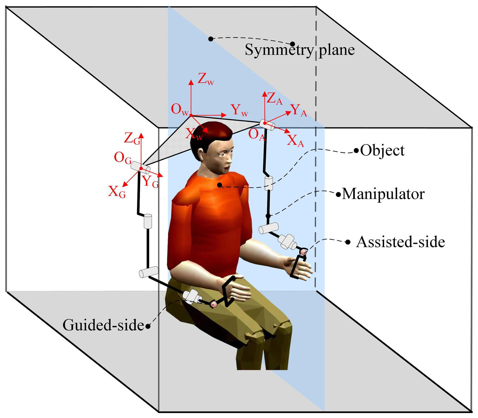
This paper defines physical interaction movements between the assisted side of the bimanual robot and the affected side of the human upper limb and between the guided side of the bimanual robot and the healthy side of the human upper limb. To analyze the mirrored pose of the robot's end effector using spatial geometric relationships, pose calibration of the robot is required. However, as the bimanual-robot platform is movable, calibration must be performed whenever the platform's position changes. To address this issue, this paper proposes that, based on the robot's kinematic model, the pose of the end effector can be determined through the mirrored relationship of the joint angles. The mirror relationship between the assisted side and guided side of the bimanual robot relative to the symmetrical plane is represented by Eqs. (1) and (2):
where and represent the end effector positions of the assisted side and guided side of the bimanual robot, respectively; and denote the joint angles of the assisted side and guided side of the bimanual robot, respectively; and f(⋅) is the forward kinematic model of the robot; is the mirror mapping matrix.
2.1 Force feedback mirroring frame based on adaptive impedance control of mirror-guide side
During interactive motion between the healthy side and the bimanual-robot-guided side, the healthy side drags the bimanual-robot-guided side. The interaction force is defined as the external force FG,ext acting on the manipulator end effector. Consequently, a dynamic equation model between the healthy side and the bimanual-robot-guided side can be established. The dynamic equation of the joint space manipulator is shown in Eq. (3):
where is the positive definite symmetric inertia matrix on the guided side of the bimanual robot; is the Gothic force or centrifugal force matrix on the guided side of the bimanual robot; is the gravity vector on the guided side of the bimanual robot; is the joint friction force vector on the guided side of the bimanual robot; is the joint driving torque vector on the guided side of the bimanual robot; is the external torque vector received by the guided side of the bimanual robot; and qG, , and are, respectively, the joint angle, angular velocity, and angular acceleration on the guided side of the bimanual robot.
The mapping relationship between the torque and angular velocity in the robot joint space and the force or moment and velocity in the task space is commonly represented using Jacobian matrices, as shown in Eqs. (4) and (5):
where is the Jacobian transpose of the manipulator.
Since the control strategy for human–robot interaction motion is performed in task space, based on Eqs. (4) and (5), the dynamic equation of the manipulator in task space is established, as shown in Eq. (6):
where is the inertia matrix vector mapped to the end effector of the manipulator; is the Coriolis force or centrifugal force vector mapped to the end effector of the manipulator; is the gravity vector mapped to the end effector of the manipulator; is the friction force vector mapped to the end effector of the manipulator; is the joint driving force vector mapped to the end effector of the manipulator; is the interaction force vector of the external environment of the manipulator; xG, , and are, respectively, the position, velocity, and acceleration vectors of the manipulator.
The Jacobian matrix defined the mapping relationship between joint velocities and linear or angular velocities (Sun et al., 2024). When a manipulator has redundant degrees of freedom or is in a singular position (i.e., n>m), even small task space velocities can result in significant joint velocities. When computing the inverse of the Jacobian matrix, it is common to construct a pseudo-inverse of the Jacobian matrix based on a positive definite symmetric weight matrix (Sun et al., 2023). Consequently, the pseudo-inverse of the Jacobian matrix on the guided side of the bimanual robot is represented as shown in Eq. (7):
During the interactive motion between the healthy side and the guided side of the bimanual robot, compliant motion of the mirror-guided side is achieved by the healthy side dragging it based on impedance control. Following Hogan's impedance control theory (Hogan, 1984), a second-order control system based on mass–damping–stiffness is established as shown in Eq. (8):
where MC is the symmetric positive definite mass matrix of the task space, DC is the symmetric positive definite damping matrix of the task space, and KC is the symmetric positive definite stiffness matrix of the task space. Equation (9) can be obtained from Eqs. (6) and (8) simultaneously.
According to Eq. (9), if ΓG(qG) is set to be equal to MC, the expected acceleration is zero, and then Eq. (9) is simplified to Eq. (10).
To prevent secondary injury on the affected side during assistance by the bimanual robot, real-time perception of the interaction force between the affected side and the mirror-assisted side by the healthy side is essential. Employing adaptive impedance control, the end effector of the bimanual robot engages in compliant interaction motion with the healthy side. In order to realize the mirror feedback of the interaction force between the two sides of the bimanual robot, adaptive adjustments of impedance controller parameters are made at the end effector. During mirror-assisted movements, the interaction motion progresses slowly, resulting in minimal influence by the damping term of the impedance controller, with interaction forces primarily being affected by stiffness parameters. Thus, by designing a stiffness parameter, a force feedback mirroring strategy for mirror-assisted movements is implemented.
The stiffness parameter consists of a stiffness coefficient matrix and a position deviation term. Real-time acquisition of the interaction force between the affected side and the mirror-assisted side is used as the influencing factor for adaptive impedance control. By combining Eqs. (6) and (8), an adaptive stiffness matrix coefficient KC can be constructed as in Eq. (12) or adaptive desired position parameters xG,e can be formulated as in Eq. (13) based on the interaction force between the affected side and the mirror-assisted side.
In the above, α is the scaling coefficient of the force feedback mirroring, and FA,ext is the human–robot interaction force on the mirror-assisted side.
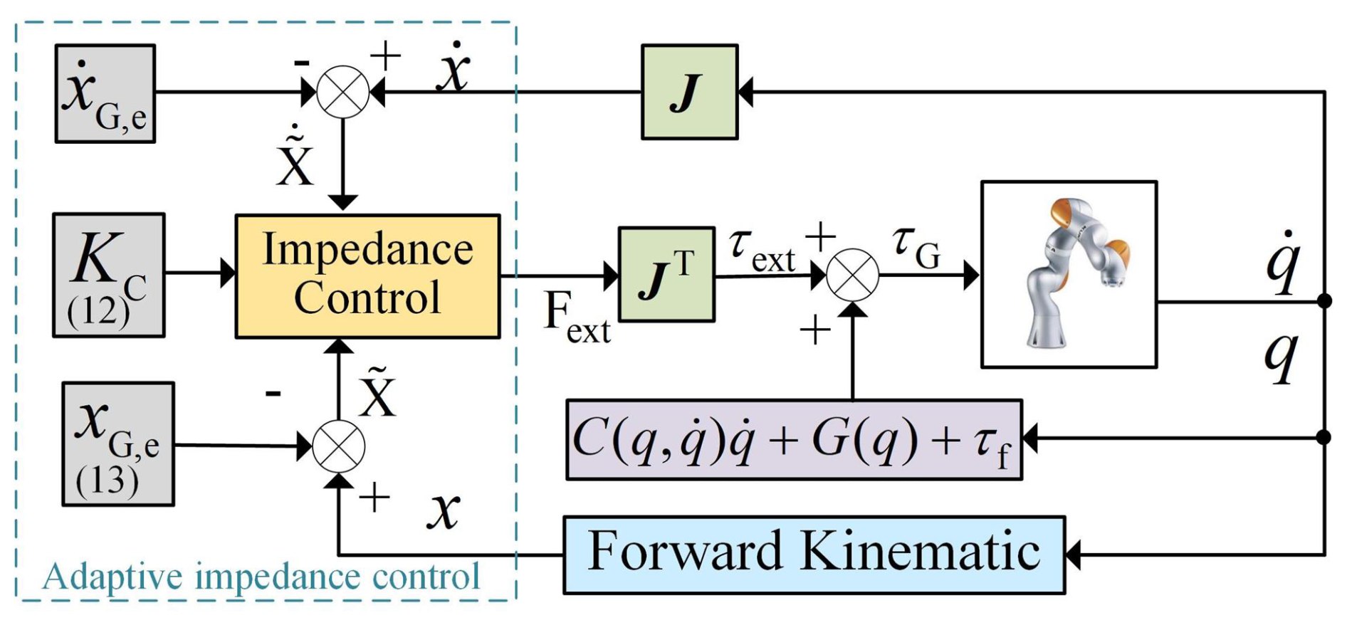
According to Eq. (12), in order to obtain adaptive stiffness parameters KC, it is necessary to set the desired position xG,e. If the desired position is set as the position from the previous servo iteration cycle, when the interaction motion pauses, the change in position approaches zero, resulting in particularly large stiffness matrix coefficients. However, as indicated by Eq. (13), to obtain adaptive desired positions, stiffness matrix coefficients KC need to be set. Considering the compliance of interaction motion, the stiffness matrix coefficients should be much smaller than those of the assisted side, and when the mirrored interaction force is too large, it may lead to desired-position settings that are beyond the workspace of the manipulator. Therefore, to construct an adaptive impedance controller, it is necessary to combine Eqs. (12) and (13), both satisfying compliant interaction at the end effector and achieving force feedback mirroring for mirror-assisted movements. The framework of the adaptive impedance control is illustrated in Fig. 2.
2.2 Mirror trajectory tracking framework based on impedance control for mirror-assisted side
Research on control methods for robot mirror-assisted movements is abundant, typically employing robot position control methods such as PID (proportional integral derivative) control, admittance control, and sliding-mode control for mirror trajectory tracking (Nisar et al., 2024). However, these mirror-assisted strategies, in the pursuit of precision in mirroring trajectory tracking, often overlook the compliance of human–robot interaction motion. This study utilizes impedance control for mirror trajectory tracking, which, although it may reduce the precision of mirrored trajectories, enhances the compliance of interaction motion between the affected side and the manipulator. The mirrored position of the guided side of the bimanual robot is derived from Eqs. (1) and (2), and this position is used as the desired position for the impedance controller on the mirror-assisted side. Subsequently, a task space impedance model for interaction motion between the healthy side and the mirror-assisted side is constructed, as shown in Eq. (14).
According to the dynamics model of the manipulator, Eq. (14) is incorporated considering the fact that human–robot interaction motion proceeds slowly, and the influence of acceleration terms is neglected. Thus, the control model for human–robot interaction motion can be simplified to Eq. (15).
2.3 Force feedback mirroring-assisted motion control framework
Compared to traditional mirror-assisted movements, force-feedback-based mirror control ensures that the magnitude of the interaction force between the healthy side and the guided side of the bimanual robot is proportional to the magnitude of the interaction force between the affected side and the assisted side of the bimanual robot. Through the bimanual robot, force feedback mirroring between the healthy and affected sides of the upper limbs is achieved to enhance the safety of mirror-assisted movements. This study employs adaptive impedance control for interaction control between the healthy side and the mirror-guided side, while damping stiffness control is used for interaction control between the affected side and the mirror-assisted side; thus, both sides of the human–robot interaction motion are based on impedance control theory.
In summary, by combining the manipulator joint space dynamic model from Eq. (3) with the impedance control models from Eqs. (8) and (17), the input torques τm and τs for the guided side and assisted side of the bimanual robot can be obtained, as shown in Eqs. (16) and (17).
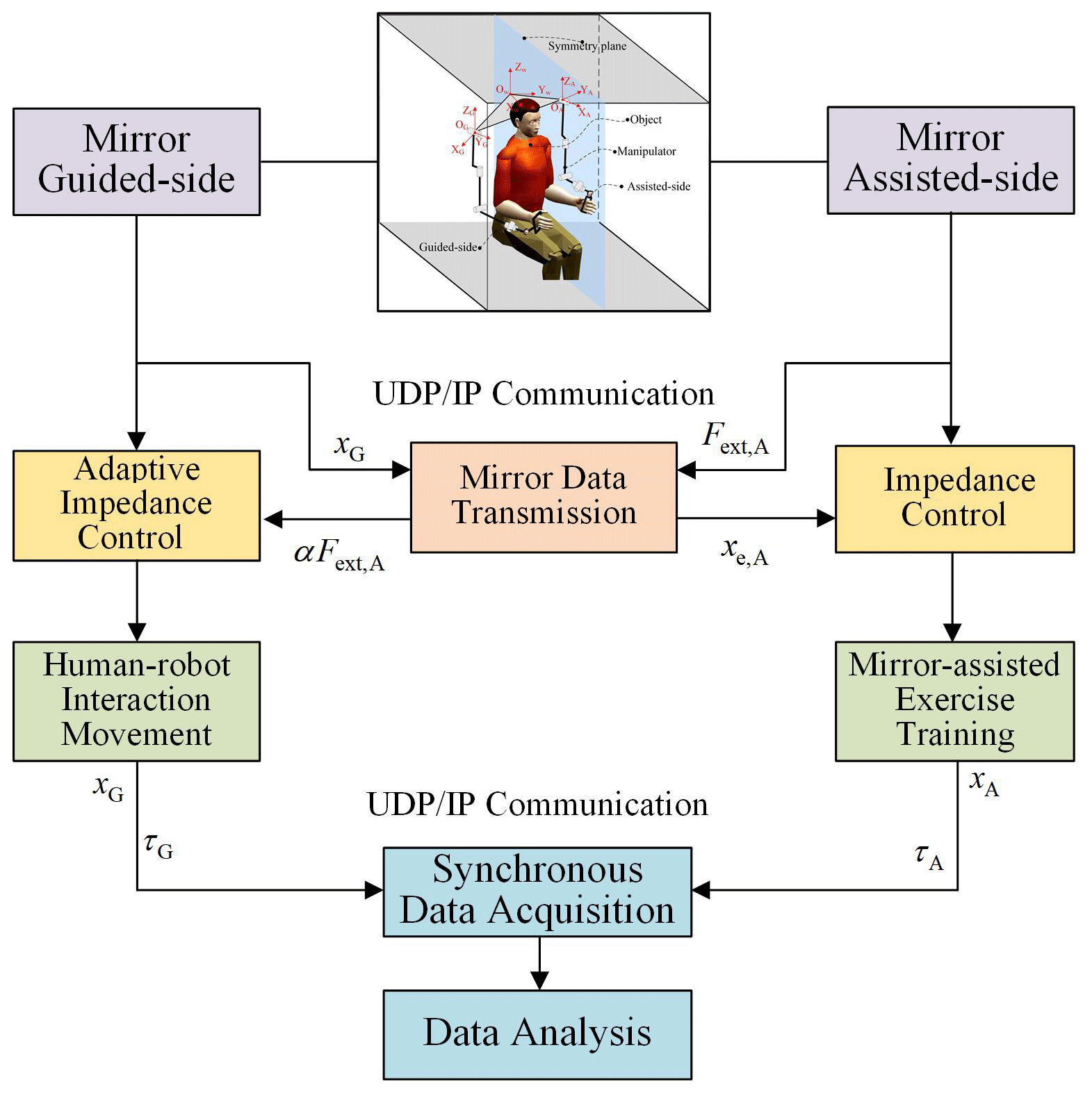
Combining Eqs. (16) and (17), a control framework for force-feedback-based mirror-assisted movement is constructed, as illustrated in Fig. 3. The control framework is divided into the assisted side and the guided side, with data exchange between the two manipulators being facilitated by the UDP/IP (User Datagram Protocol/Internet Protocol) communication protocol.
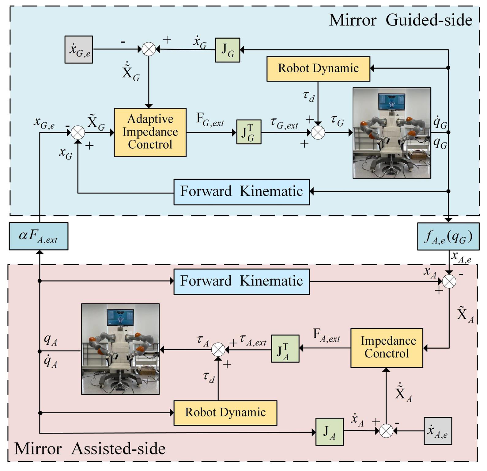
According to Fig. 3, based on adaptive impedance control, the guided side of the bimanual robot interacts physically with the healthy side, mapping the mirrored pose of the guided side to the mirror-assisted side in real time. This enables the mirror-assisted side to assist the affected side in mirroring trajectory tracking. Simultaneously, the assistance force from the mirror-assisted side is mapped to the guided side of the bimanual robot. By adjusting the influencing factor of the adaptive impedance controller, force feedback mirroring between the mirror-assisted side and the mirror-guided side is achieved.
In this section, the experimental results are presented to demonstrate the feasibility of the proposed force feedback mirroring-assisted movement strategy. The purpose of the experiments is to test the functionality of the controller rather than to conduct clinical biological responses or medical trials with patients; hence, the experiments involved only healthy participants. The control method proposed in this paper is implemented on an end-effector-based upper-limb bilateral rehabilitation robot platform.
3.1 Bilateral mirror training system
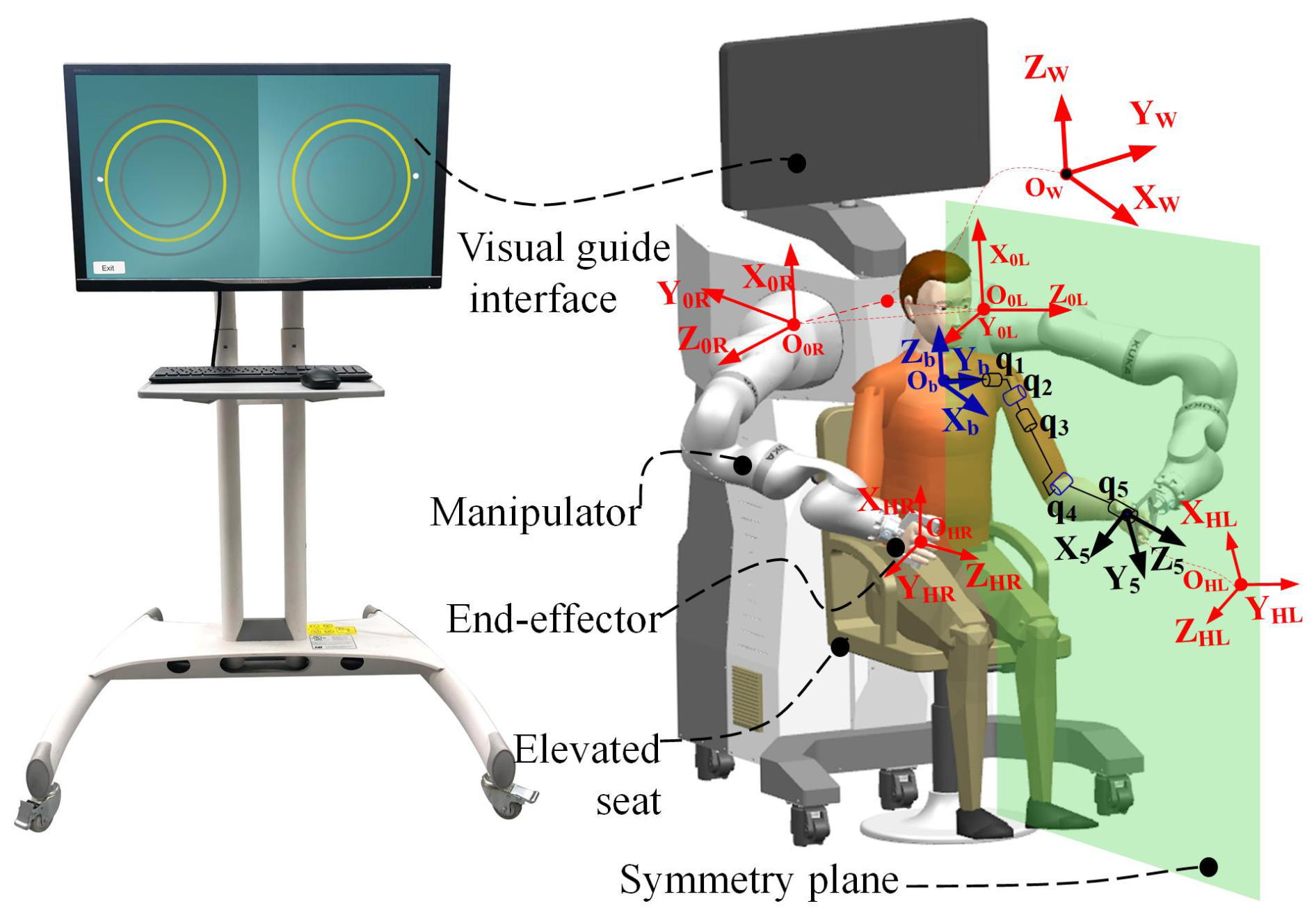
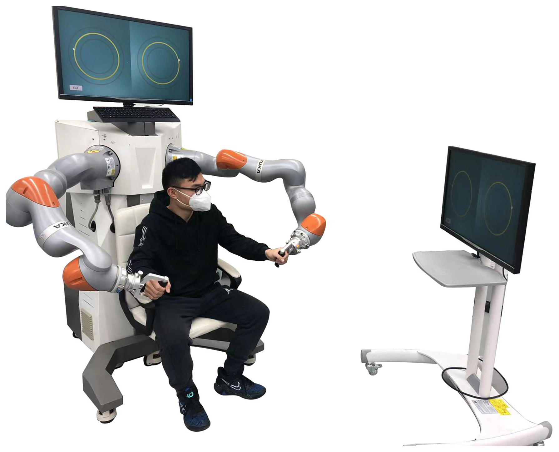
The model of the upper-limb bilateral motion assistance training platform developed by the research group is depicted in Fig. 4, consisting mainly of a PC host, an adjustable seat, a display screen, and two KUKA IIWA manipulators. Additionally, both the software and hardware of the upper-limb bilateral rehabilitation training platform are equipped with emergency stop functions (Sun et al., 2023). The transformation relationship between the coordinate systems of the bimanual-robot system is illustrated on the right side of Fig. 4. Here, OW−XYZ represents the world coordinate system of the robot, OL−XYZ represents the base coordinate system of the left manipulator, OR−XYZ represents the base coordinate system of the right manipulator, OHR−XYZ represents the coordinate system of the physical interaction point on the right side, and OHL−XYZ represents the coordinate system of the physical interaction point on the left side. The visually guided interaction interface is depicted on the left side of Fig. 4, featuring two yellow circles representing the desired trajectories for the left and right sides, along with a virtual motion channel created based on these trajectories. Compared to other rehabilitation devices, this platform is utilized for end-effector-based upper-limb assistance training, enabling both unilateral and bilateral upper-limb assistance training strategies.
The control strategy proposed in this paper is implemented by writing programs in C++ language on the Ubuntu Linux operating system. Data transmission between the PC and the manipulator control cabinet is facilitated via UDP/IP communication based on the FRI (Fast Research Interface) library, with a real-time module achieving a maximum speed of up to 1 kHz (Schreiber et al., 2010). Additionally, the real-time module of the manipulator also supports external torque control, with its control rate being outlined in Eq. (18):
where represents the controller input torque vector, represents the stiffness matrix of the impedance controller in the internal task space of the robot, denotes the desired position in the task space, represents the real-time pose of the manipulator in the task space, represents the force generated by the damping term inside the robot, denotes the externally superimposed torque vector, and denotes the dynamics term of the robot.
In order to realize force feedback mirroring based on the mirror-assisted motion of a bimanual robot, a human–robot physical interaction method based on adaptive impedance control is proposed. This method enables the robotic assistance of the affected side to track mirrored trajectories while also facilitating force feedback mirroring between the healthy and affected sides. The magnitude of mirrored interaction forces can be adjusted by means of proportional influence factor coefficients. Moreover, participants can use their active forces to correct trajectories instead of strictly adhering to reference trajectories, enhancing the compliance of mirror-assisted movements. The input torque of the human–robot interaction controller on the mirror-guided side is calculated using Eq. (15), and by combining Eqs. (8), (12), and (13), the external input torque can be obtained, as shown in Eq. (19).
3.2 Subject
The experimental testing in this study involved five healthy male participants (average age of 25.6 years, average height of 175 cm) with no upper-limb movement disorders. Participants sat on an adjustable-height seat, facing away from the robot, for bilateral mirror-assisted movement training, as shown in Fig. 5. Additionally, participants imitated the affected-side movements of stroke patients with their non-dominant hand and the healthy-side movements of stroke patients with their dominant hand. Since this study focuses on the feasibility of the force feedback mirroring strategy in robot mirror-assisted locomotion, factors such as compensatory movements by patients were disregarded, ensuring the validity of the experimental results.
3.3 Design of experiment
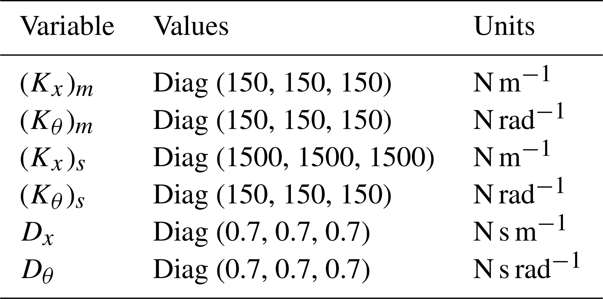
To validate the feasibility of the proposed method, a set of mirror-assisted training exercises designed for planar task orientation was developed. The flowchart illustrating the data transmission and computation process is shown in Fig. 6. Based on the analysis of dexterity within the workspace and the distribution of human–robot interaction dexterity in bilateral upper-limb rehabilitation robots, discussed as a reference (Sun et al., 2021), a circular desired trajectory was constructed within the plane at mm. The center of the circle was located at position [655 mm, −552 mm, −425 mm] in the robot's coordinate system OR−XYZ, with a radius of 100 mm. Additionally, a virtual channel with the desired trajectory as its centerline and a radius of 25 mm was created. Real-time position information of the end effector of the manipulator was transmitted to a visualization interface built using Unity 3D software, providing real-time visual feedback. The data transmission frequency between the guided side and assisted side of the bimanual robot, as well as between the manipulator and Unity 3D, was set to 500 Hz using the UDP/IP data communication protocol. Participants were instructed to move their healthy side along the desired trajectory within the virtual channel as much as possible. Furthermore, the interaction force ratio coefficient between the mirror-assisted side and the guided side was set to 3, and the stiffness matrix and damping ratio matrix for the task space impedance controller of the affected side were configured, with detailed parameter data provided in Table 1.
3.4 Results
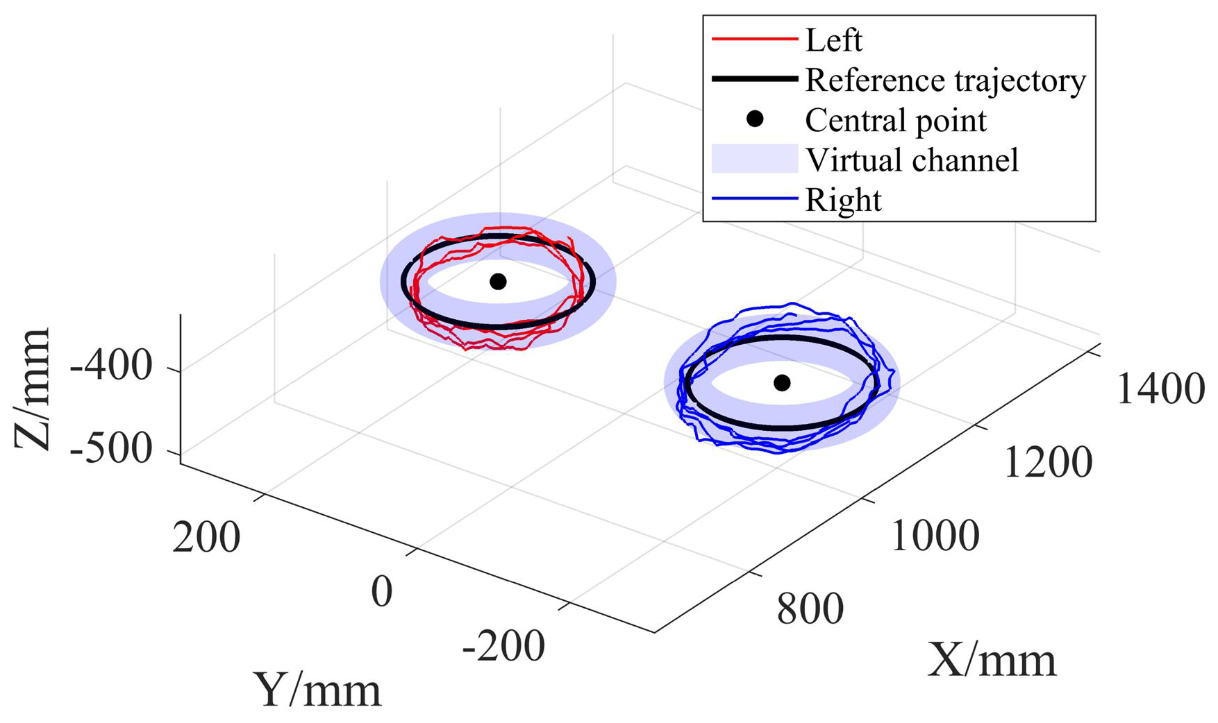
The participants engaged in four rounds of circular trajectories for bilateral mirror movements guided by visual cues. Data on joint angle transformations for the two manipulators were obtained through position sensors and UDP/IP communication. Subsequently, the motion trajectory of the human–robot interaction points in coordinate system OW−XYZ was computed based on the forward kinematics of the manipulator. Taking the test results of participant one as an example, the motion trajectory is illustrated in Fig. 7. In Fig. 7, the red trajectory represents the movement trajectory of the participant's left hand, the black trajectory represents the reference trajectory, the black dot indicates the center of the constructed reference trajectory, light blue denotes the virtual channel constructed, and the blue trajectory represents the movement trajectory of the participant's right hand.
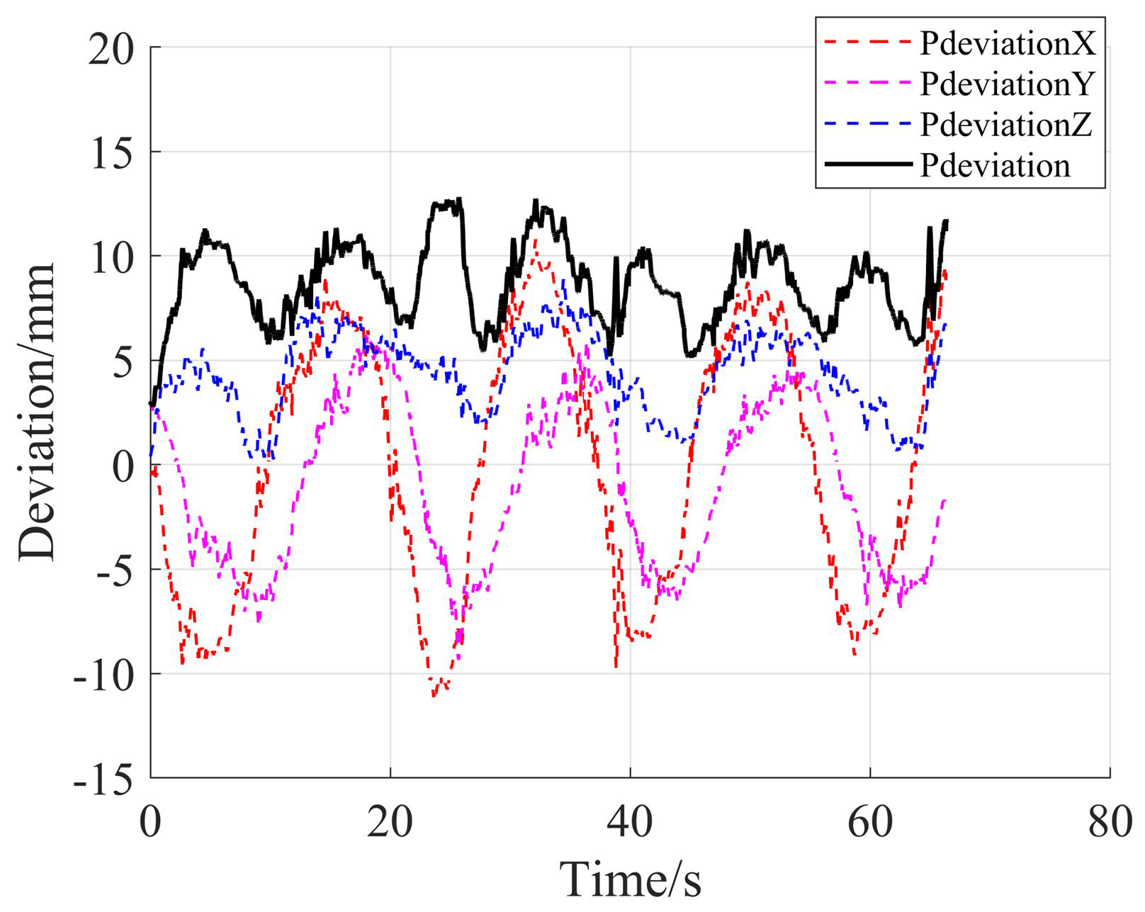
To analyze the trajectory deviation during mirror trajectory tracking based on impedance control, real-time position information of both the assisted side and guided side of the bimanual robot was synchronously recorded, and their mirror deviation changes were calculated based on the principle of mirror symmetry. Taking the test results of participant one as an example, the bilateral mirror trajectory deviation changes are illustrated in Fig. 8. In Fig. 8, the dashed red line represents the positional deviation in the x-axis direction during bilateral mirror movements, the dashed pink line represents the positional deviation in the y-axis direction during bilateral mirror movements, the dashed blue line represents the positional deviation in the z-axis direction during bilateral mirror movements, and the solid black line represents the positional deviation during bilateral mirror movements.
To test the feasibility of force feedback mirroring based on adaptive impedance control, external forces were detected in real-time using joint torque sensors of the robot, and the interaction force between the human and the end effector of the manipulator was calculated using Eq. (4). The variations in interaction forces on both the assisted side and guided side of the bimanual robot were synchronously recorded in real time. Taking the test results of participant one as an example, the changes in bilateral interaction forces are illustrated in Fig. 9. The left side of Fig. 9 represents the scale values of the interaction force magnitude, while the right side represents the scale values of the interaction force ratio coefficients. The solid blue line represents the variation in the assistance force exerted on the participant's left side by the manipulator, the dashed blue line represents the variation in the resistance force exerted on the participant's right side by the manipulator, the solid red line represents the variation in the ratio of the assistance force on the participant's left side to the resistance force on the participant's right side during bilateral mirror movements, and the dashed red line represents the variation in the theoretical ratio of the assistance force on the participant's left side to the resistance force on the participant's right side during bilateral mirror movements.
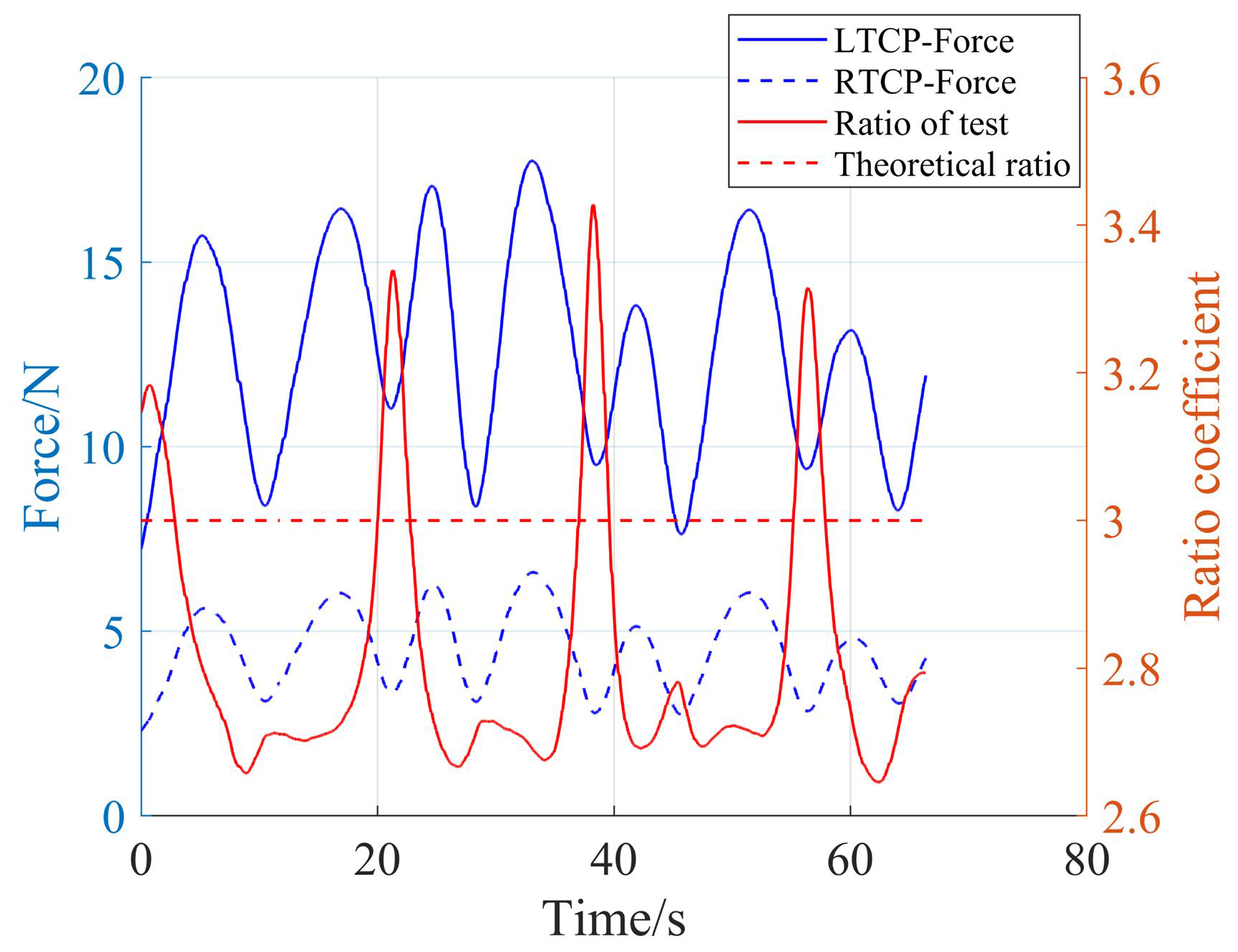
According to Fig. 9, the ratio between the assistance force exerted by the manipulator on the subject's left side and the resistance force applied on the right side shows a maximum deviation of approximately 0.4 between the theoretical and actual values. The discrepancy between the theoretical and experimental results can primarily be attributed to factors such as measurement errors from the sensors, compensation errors in the friction modeling of the robot's dynamics, and synchronization errors during data acquisition.
Finally, the average trajectory deviation and interaction force ratio of each participant during bilateral force feedback mirror-assisted movements were statistically analyzed, as depicted in Fig. 10. The left side of Fig. 10 represents the scale values of the average trajectory deviation magnitude, while the right side represents the scale values of the interaction force ratio coefficients. The blue line indicates the variations in the mean values of mirror trajectory deviations for each participant, while the red line represents the variations in the mean values of the interaction force ratios for each participant.
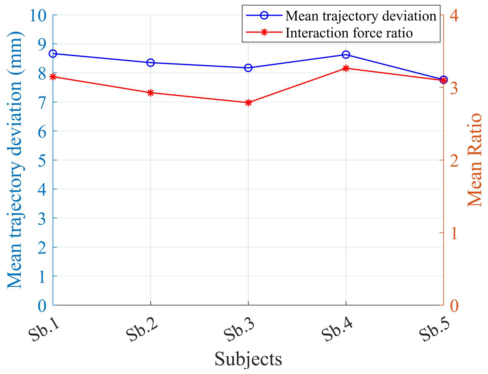
Figure 10Changes in mean mirror trajectory bias and interaction force ratio for five subjects.
3.5 Discussion
From the test results depicted in Fig. 8, it is evident that the average deviation between the affected-side trajectory and the healthy-side trajectory is approximately 8.7 mm. When mirror-assisted trajectory tracking is conducted on the mirror-assisted side based on impedance control, a certain degree of deviation is permitted, thereby enhancing the compliance of interaction between the affected side and the robot. Moreover, Fig. 7 reveals the presence of periodicity in the deviation changes. The trajectory tracking on the affected side in this study is based on fixed stiffness impedance control, as demonstrated in Fig. 8, which also exhibits periodic changes in the assistance force of the manipulator. This suggests the existence of certain biomechanical characteristics when participants engage in periodic circular trajectory movements; specific regions indicate smoother upper-limb movements and vice versa. Figure 8 illustrates that the average ratio of the assistance force exerted on the participant's left side to the resistance force exerted on the participant's right side is 3.14, while the ratio set in this study is 3, indicating the presence of interaction force mirroring deviation. Part of the reason for this discrepancy is the measurement deviation of the sensors. Additionally, Fig. 9 indicates that the average ratio of the assistance force exerted on the left side of the five participants to the resistance force exerted on their right side fluctuates around 3, with the mirror trajectory deviation being around 8.4 mm.
In conclusion, the force feedback mirror-assisted motion constructed based on adaptive impedance control can mirror the force feedback of bilateral mirror-assisted motion to a certain extent, which verifies the feasibility of the proposed method.
The shortcomings of this study are as follows. (1) The parameters selected for task space impedance control in the experimental tests were not optimal, and the issue of torque generated by task space rotational layer impedance control was not investigated, necessitating further optimization in subsequent studies. (2) In the mirror-assisted movement studied in this paper, impedance control was used for trajectory tracking on the affected side, which increased the compliance of human–robot interaction but reduced the accuracy of trajectory tracking. The stiffness coefficient of the impedance control needs further optimization. (3) Only healthy subjects were selected for experimental testing to validate the proposed control strategy in this study, necessitating further recruitment of patients for clinical testing to enhance the effectiveness and persuasiveness of the proposed method.
In the next phase of our research, we plan to conduct clinical experiments with patients to further validate the effectiveness of the method proposed in this paper. Future research will focus on (1) experimental validation of mirror-assisted movement in hemiplegic patients with upper-limb motor dysfunction and (2) implementing ADL (activity of daily living) tasks using virtual-reality technology, providing patients with auditory or visual feedback and incentive rewards to enhance motivation for rehabilitation training.
This paper proposes a force feedback mirror-assisted strategy based on adaptive impedance control. In this strategy, the subject's unimpaired side drags the mirror-guided side for physical interaction movement based on the adaptive impedance control, while the mirror-assisted side, using impedance control, aids the impaired side in tracking the mirror trajectory so as to realize the mirror synchronous movement between the two sides of the subject.
The system employs UDP/IP communication to obtain the real-time interaction forces between the impaired side and the mirror-assisted side, allowing the unimpaired side to assist the impaired side's mirrored movements via a bimanual robotic system. Additionally, a force feedback mechanism enables real-time perception of proportional assistive forces applied by the mirror-assisted side, thereby enhancing the safety of mirror training.
Experimental tests indicate that the bimanual robotic system effectively applies assistive or impedance forces to the subject's impaired and unimpaired sides in accordance with the predefined proportional coefficients. Although minor deviations were observed in the mirror trajectory, the experimental results demonstrate the feasibility of the proposed strategy in achieving both trajectory mirroring and force feedback mirroring, providing a solid theoretical foundation for further optimization of rehabilitation training systems.
The data that support the findings of this study are available from the corresponding author upon reasonable request.
QS conceived the idea and drafted the paper. QL, NG, and JN discussed and edited the paper. QS finalized the paper, including preparing the detailed response letter.
The contact author has declared that none of the authors has any competing interests.
Publisher's note: Copernicus Publications remains neutral with regard to jurisdictional claims made in the text, published maps, institutional affiliations, or any other geographical representation in this paper. While Copernicus Publications makes every effort to include appropriate place names, the final responsibility lies with the authors.
The authors are grateful to the anonymous reviewers and the editor for their comments and suggestions, which helped to improve our paper.
This research has been supported by the Key R&D Program of Zhejiang Province (grant no. 2023C01181).
This paper was edited by Zi Bin and reviewed by two anonymous referees.
Cai, S., Chen, Y., Huang, S., Wu, Y., Zheng, H., Li, X., and Xie, L.: SVM-based classification of sEMG signals for upper-limb self-rehabilitation training, Front. Neurorobotics, 13, 1–10, https://doi.org/10.3389/fnbot.2019.00031, 2019.
Chen, J., Hu, D., Sun, W., Tu, X., and He, J.: A novel telerehabilitation system based on bilateral upper limb exoskeleton robot, 2019 IEEE International Conference on Real-time Computing and Robotics (RCAR), 4–9 August 2019, Irkutsk, Russia, 391–396, https://doi.org/10.1109/RCAR47638.2019.9044072, 2019.
Dhakate, D. and Bhattad, R.: Study the effectiveness of bilateral arm training on upper extremity motor function and activity level in patients with sub-acute stroke, International Journal of Current Research and Review, 12, 31–37, https://doi.org/10.31782/IJCRR.2020.122012, 2020.
Harischandra, P. A. D. and Abeykoon, A. M. H.: Intelligent bimanual rehabilitation robot with fuzzy logic based adaptive assistance, International Journal of Intelligent Robotics and Applications, 3, 59–70, https://doi.org/10.1007/s41315-019-00080-9, 2019.
Harmsen, W. J., Bussmann, J. B. J., Selles, R. W., Hurkmans, H. L. P., and Ribbers, G. M.: A mirror therapy–based action observation protocol to improve motor learning after stroke, Neurorehab. Neural Re., 29, 509–516, https://doi.org/10.1177/1545968314558598, 2015.
Hogan, N.: Impedance Control: An Approach to Manipulation, 1984 IEEE American Control Conference, 6–8 June 1984, San Diego, CA, USA, https://doi.org/10.23919/ACC.1984.4788393, 1984.
Kim, W., Beom, J., Park, C., Koh, S., Kim, Y., Chung, S., and Kim, S.: Reliability and validity of attitude and heading reference system motion estimation in a novel mirror therapy system, J. Med. Biol. Eng., 38, 370–377, https://doi.org/10.1007/s40846-017-0315-4, 2018.
Li, M., Zhang, J., Zuo, G., Feng, G., and Zhang, X.: Assist-as-needed control strategy of bilateral upper limb rehabilitation robot based on GMM, Machines, 10, 76, https://doi.org/10.3390/machines10020076, 2022.
Miao, Q., McDaid, A., Zhang, M., Kebria, P., and Li, H.: A three-stage trajectory generation method for robot-assisted bilateral upper limb training with subject-specific adaptation, Robot. Auton. Syst., 105, 38–46, https://doi.org/10.1016/j.robot.2018.03.010, 2018.
Miao, Q., Zhang, M., McDaid, A., Peng, Y., and Xie, S.: A robot-assisted bilateral upper limb training strategy with subject-specific workspace: A pilot study, Robot. Auton. Syst., 124, 103334, https://doi.org/10.1016/j.robot.2019.103334, 2020.
Nam, H. S., Koh, S., Beom, J., Kim, Y. J., Park, J. W., Koh, E. S., Chung, S. G., and Kim, S.: Recovery of proprioception in the upper extremity by robotic mirror therapy: A clinical pilot study for proof of concept, J. Korean Med. Sci., 32, 1568–1575, https://doi.org/10.3346/jkms.2017.32.10.1568, 2017.
Nisar, H., Annamraju, S., Deka, S. A., Horowitz, A., and Stipanovic, D. M: Robotic mirror therapy for stroke rehabilitation through virtual activities of daily living, Computational and Structural Biotechnology Journal, 24, 126–135, https://doi.org/10.1016/j.csbj.2024.01.017, 2024.
Noskin, O., Krakauer, J. W., Lazar, R. M., Festa, J. R., Handy, C., O'Brien, K. A., and Marshall, R. S.: Ipsilateral motor dysfunction from unilateral stroke: implications for the functional neuroanatomy of hemiparesis, J. Neurol. Neurosur. Ps., 79, 401–406, https://doi.org/10.1136/jnnp.2007.118463, 2008.
Park, K., Kim, Y. W., Nagai, C., and Obinata, G.: Investigation of human mirror-image for bilateral movement training of upper limb rehabilitation, 2010 International Symposium on Micro-NanoMechatronics and Human Science, 7–10 November 2010, Nagoya, Japan, 402–407, https://doi.org/10.1109/MHS.2010.5669514, 2010.
Piscitelli, D., Turpin, N. A., Subramanian, S. K., Feldman, A. G., and Levin, M. F.: Deficits in corticospinal control of stretch reflex thresholds in stroke: Implications for motor impairment, Clin. Neurophysiol., 131, 2067–2078, https://doi.org/10.1016/j.clinph.2020.05.030, 2020.
Rossiter, H. E., Borrelli, M. R., Borchert, R. J., Bradbury, D., and Ward, N. S.: Cortical mechanisms of mirror therapy after stroke, Neurorehab. Neural Re., 29, 444–452, https://doi.org/10.1177/1545968314554622, 2015.
Schreiber, G., Stemmer, A., and Bischoff, R.: The fast research interface for the kuka lightweight robot, IEEE workshop on innovative robot control architectures for demanding (Research) applications how to modify and enhance commercial controllers (ICRA 2010), Citeseer, 15–21, 2010.
Shahbazi, M., Atashzar, S. F., Tavakoli, M., and Patel, R. V.: Robotics-assisted mirror rehabilitation therapy: a therapist-in-the-loop assist-as-needed architecture, IEEE-ASME T. Mech., 21, 1954–1965, https://doi.org/10.1109/TMECH.2016.2551725, 2016.
Sheng, B., Xie, S., Tang, L., Deng, C., and Zhang, Y.: An industrial robot-based rehabilitation system for bilateral exercises, IEEE Access, 7, 151282–151294, https://doi.org/10.1109/ACCESS.2019.2948162, 2019.
Sun, Q., Guo, S., and Zhang, L.: Kinematic dexterity analysis of human-robot interaction of an upper limb rehabilitation robot, Technol. Health Care, 29, 1029–1045, https://doi.org/10.3233/THC-202633, 2021.
Sun, Q., Guo, S., and Fei, S.: Collision avoidance analysis of human–robot physical interaction based on null-space impedance control of a dynamic reference arm plane, Med. Biol. Eng. Comput., 61, 2077–2090, https://doi.org/10.1007/s11517-023-02850-x, 2023.
Sun, Q., Guo, S., Zhang, L., and Fei, S.: Research on human-robot physical interaction control based on adaptive impedance control, J. Mech. Med. Biol., 24, 2350052, https://doi.org/10.1142/S0219519423500525, 2024.
Tai, R. Y., Zhu, J. D., Cheng, C. H., Tseng, Y. J., Chen, C. C., and Hsieh, Y. W.: Cortical neural activity evoked by bilateral and unilateral mirror therapy after stroke, Clin. Neurophysiol., 131, 2333–2340, https://doi.org/10.1016/j.clinph.2020.06.030, 2020.
Wang, W. and Fu, L.: Mirror therapy with an exoskeleton upper-limb robot based on IMU measurement system, 2011 IEEE International Symposium on Medical Measurements and Applications, 30–31 May 2011, Bari, Italy, 370–375, https://doi.org/10.1109/MeMeA.2011.5966732, 2011.
Wu, J., Cheng, H., Zhang, J., Bai, Z., and Cai, S.: The modulatory effects of bilateral arm training (BAT) on the brain in stroke patients: a systematic review, Neurol. Sci., 42, 501–511, https://doi.org/10.1007/s10072-020-04854-z, 2021.
Yang, Y., Zhao, Q., Zhang, Y., Wu, Q., Jiang, X., and Cheng, G.: Effect of mirror therapy on recovery of stroke survivors: a systematic review and network meta-analysis, Neuroscience, 390, 318–336, https://doi.org/10.1016/j.neuroscience.2018.06.044, 2018.
Yang, Z., Guo, S., Liu, Y., Kawanishi, M., and Hirata, H.: A task performance-based sEMG-driven variable stiffness control strategy for upper limb bilateral rehabilitation system, IEEE-ASME T. Mech., 28, 792–803, https://doi.org/10.1109/TMECH.2022.3208610, 2022.
Yang, Z., Guo, S., Suzuki, K., Liu, Y., and Kawanishi, M.: An EMG-based biomimetic variable stiffness modulation strategy for bilateral motor skills relearning of upper limb elbow joint rehabilitation, J. Bionic Eng., 20, 1597–1612, https://doi.org/10.1007/s42235-023-00339-9, 2023.