the Creative Commons Attribution 4.0 License.
the Creative Commons Attribution 4.0 License.
 | 19 Jun 2025
A novel crane-like launch and recovery system for multiple USVs: mechanism design, control strategy, and experimental validation
Dan-Jun Zhang
Xing-Hua Xiao
Guang Li
Chun-Xin Li
Yi Yang
To enhance safety in offshore operations and minimize modifications to the mother ship, an autonomous crane-like launch and recovery (LAR) system is essential for deploying and retrieving uncrewed surface vehicles (USVs). Traditional crane-like LAR systems are typically designed for handling a single USV, limiting operational efficiency. This paper proposes a novel crane-like LAR system capable of launching and recovering multiple USVs, improving efficiency and convenience. The system consists of a foldable crane arm, three floating brackets, two configuration control mechanisms (CCMs), and a lifting and lowering mechanism. The design and analysis of the foldable crane arm and CCMs are presented in detail. Furthermore, a vision-guided autonomous docking and recovery control strategy is proposed to enable autonomous docking operations. To validate the system, a prototype was developed, and comprehensive experiments were conducted. The results demonstrate that the system successfully recovers three USVs with smooth and stable motion.
- Article
(14102 KB) - Full-text XML
- BibTeX
- EndNote


In recent years, there has been significant growth in the global research and development of uncrewed surface vehicles (USVs) (Liu et al., 2016; Bai et al., 2022; Er et al., 2023). Due to the range limitations of USVs, they are typically transported to designated areas by a mother ship and then deployed on the water to begin their missions. After completing the missions, the USVs are retrieved back onto the mother ship's deck (Jorge et al., 2019; Pu et al., 2020). In this process, an autonomous launch and recovery system is essential for the deployment and retrieval of USVs (Zhang et al., 2018; Dong et al., 2023). Currently, autonomous launch and recovery systems for USVs can be classified into three main categories: ramps/slipways, well decks, and crane-like systems (Yu et al., 2021; Zhou et al., 2023; Rout et al., 2024). The first two systems demand significant structural modifications to the mother ship, limiting their adaptability and making them unsuitable for widespread adoption at this stage. In contrast, the crane-like system requires minimal modifications to the mother ship, allowing for quicker and broader implementation.
Several research institutes and companies have developed crane-like launch and recovery (LAR) systems for uncrewed surface vessels (USVs). RC DOCK developed two types of LAR systems for USVs: the D-LARS and S-LARS (RC Dock Engineering BV, 2024). The D-LARS is a dual-point suspended LAR system, while the S-LARS is a single-point suspended one. The LAR system designed by SEALARTEC successfully completed sea trials, featuring a hydraulic floating bracket and a machine vision docking control program (Sealartec, 2024). Shanghai University developed two types of LAR systems (Yang et al., 2020; Chen et al., 2019): the pneumatic ejection type and the floating bracket type, both of which have successfully completed sea trials.
Traditional crane-like LAR systems were designed only for the deployment and recovery of a single USV (Kouriampalis et al., 2021; Chen et al., 2020; Wang et al., 2024), and there is currently no solution for the simultaneous deployment and recovery of multiple USVs. To make the launch and recovery of USVs more efficient and convenient, this paper explores autonomous launch and recovery technologies for multiple USVs. Compared to single-USV LAR systems, multi-USV LAR systems present the following challenges:
- 1.
Structural constraints. The crane arm must be redesigned to accommodate the simultaneous launch and recovery of multiple USVs while ensuring compatibility with the limited installation space on the mother ship.
- 2.
Flow field interference. The deployment and recovery process is influenced by hydrodynamic interactions between USVs, as well as between the USVs and the mother ship. To mitigate these effects, the positions and postures of multiple floating brackets (i.e., their configuration) should be adjustable, allowing for different USV deployment and recovery formations that minimize flow field disturbances.
- 3.
Autonomous docking control. A suitable control strategy must be implemented to ensure that multiple USVs can autonomously and orderly enter their corresponding floating brackets.
To address these challenges, we propose the following solutions: (1) a novel foldable crane arm design that offers compactness, a large extension range, and smooth motion; (2) a configuration control mechanism (CCM) to adjust the lateral and longitudinal distances between multiple floating brackets, minimizing flow field disturbances; and (3) a two-stage partitioned guidance control scheme to enable the autonomous docking of multiple USVs with the floating brackets.
The remainder of the paper is structured as follows. Section 2 introduces a novel crane-like LAR mechanism designed for the simultaneous deployment and recovery of three USVs. This system includes key components such as a foldable crane arm, three floating brackets, two configuration control mechanisms, and a lifting/lowering mechanism. Section 3 discusses the design of the foldable crane arm, which minimizes its footprint when retracted and allows significant extension. An evaluation performance function, considering the folded volume of the crane arm and the lever arm, is proposed, and crane arm parameters are optimized accordingly. Section 4 analyzes the hydrodynamic interactions among the three floating brackets during the deployment and recovery processes. The CCMs are designed to adjust the lateral and longitudinal distances between the floating brackets to minimize disturbances. Sections 5 and 6 present a two-stage partitioned guidance control scheme for the autonomous docking of multiple USVs with the floating brackets. Vision-based docking methods, previously used for autonomous underwater vehicles (AUVs) (Li et al., 2015; Kong et al., 2024), are adapted for the recovery of three USVs. Section 7 describes the fabrication of a prototype and presents the results of experimental validation.
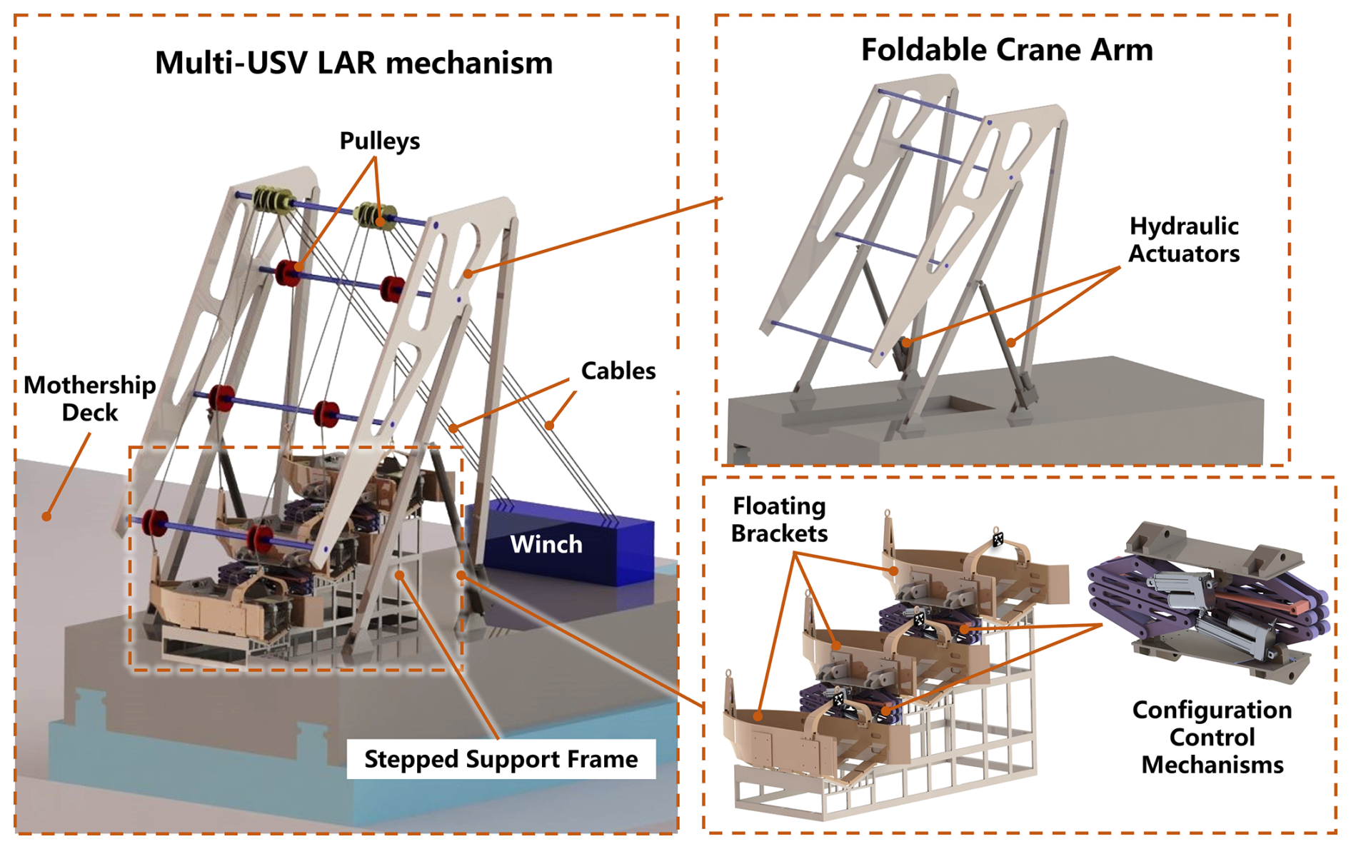
The crane-like LAR mechanism developed in this study features a foldable design, optimizing installation space on the mother ship. To enable the simultaneous launch and recovery of three USVs, the mechanism is equipped with three floating brackets. These brackets hold the USVs and facilitate launch and recovery on the water's surface, allowing the USVs to sail in and out of them.
The multi-USV LAR mechanism consists of several key components, including a foldable crane arm, three floating brackets, two configuration control mechanisms (CCMs), and a lifting and lowering system. The crane arm, employing a dual-rocker mechanism, can extend and retract, driven synchronously on both sides by hydraulic actuators. The floating brackets are designed to lock and release the USVs, enabling them to be lifted and lowered from the mother ship. Each bracket is connected to winches via six cables and a series of pulleys, which facilitate the lifting and lowering process. The three floating brackets with the three USVs can be placed horizontally on a stepped support frame. Additionally, each pair of floating brackets is equipped with a CCM, which adjusts their posture and position. This adjustment minimizes flow field interference, particularly when the floating brackets are in close proximity on the water's surface. An illustrative diagram of the multi-USV LAR mechanism is presented in Fig. 1.
During transport, the LAR mechanism retracts to minimize its footprint on the vessel. When deployment or recovery of USVs is required, the mechanism unfolds, extending the crane arm beyond the side of the ship and lowering three floating brackets into the water. Once the brackets are positioned on the water's surface, two CCMs adjust the brackets' posture and position, ensuring the USVs can safely navigate out of the brackets. The floating brackets then release their locks, allowing the USVs to autonomously exit one by one. After all three USVs are deployed, the LAR mechanism retracts, returning to its original position and completing the deployment process, as illustrated in Fig. 2.
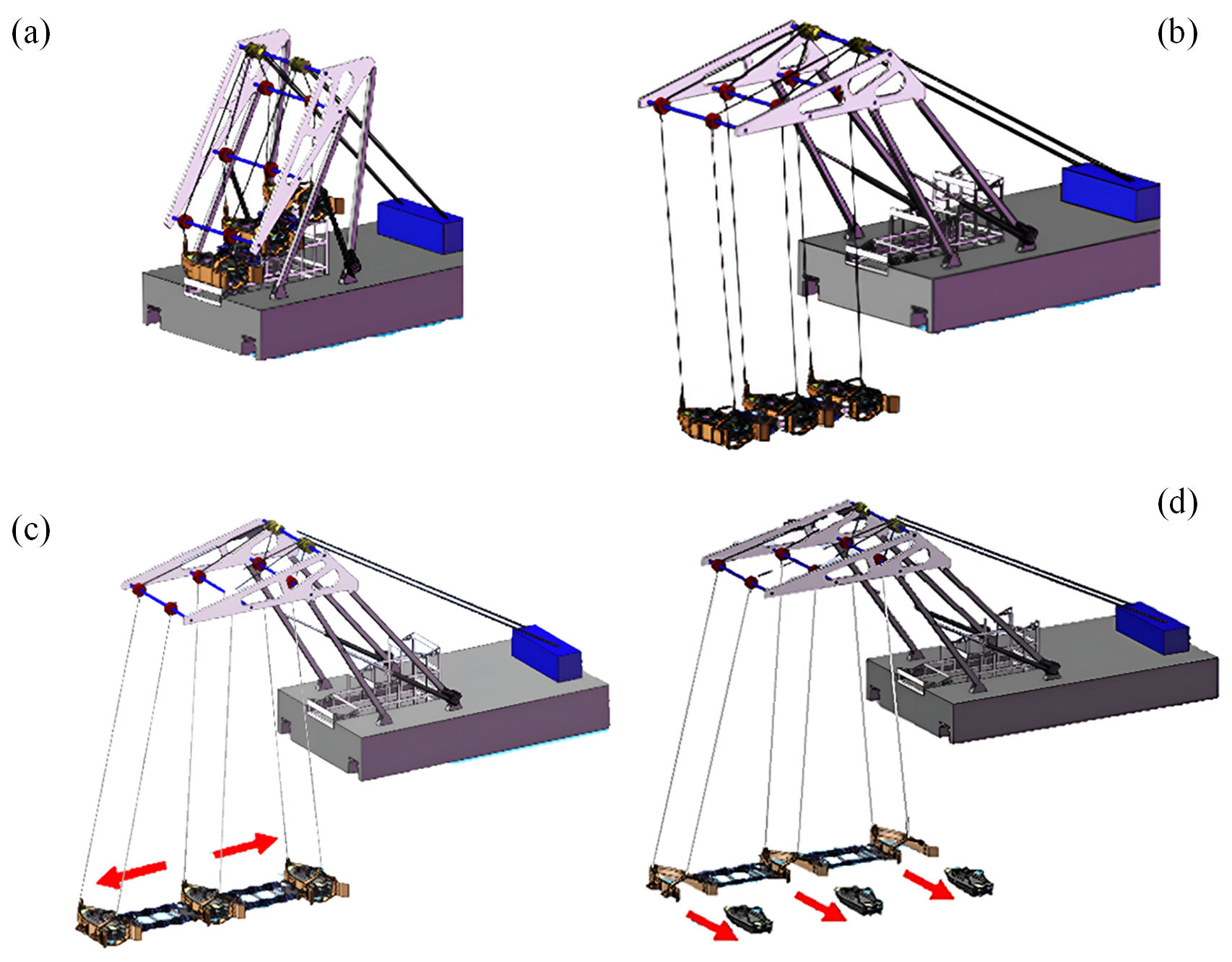
Figure 2Deployment of multiple USVs using the LAR mechanism: (a) folded LAR mechanism, (b) extending the crane arm and lowering three floating brackets, (c) adjusting the configuration of the brackets, and (d) autonomous sailing of USVs.
The recovery process essentially reverses the deployment procedure. The USVs autonomously approach and lock into the floating brackets in sequence, after which a winch lifts the brackets to the proper position. Finally, the crane arm folds, completing the recovery operation.
The overall launch and recovery control process is shown in Fig. 3.
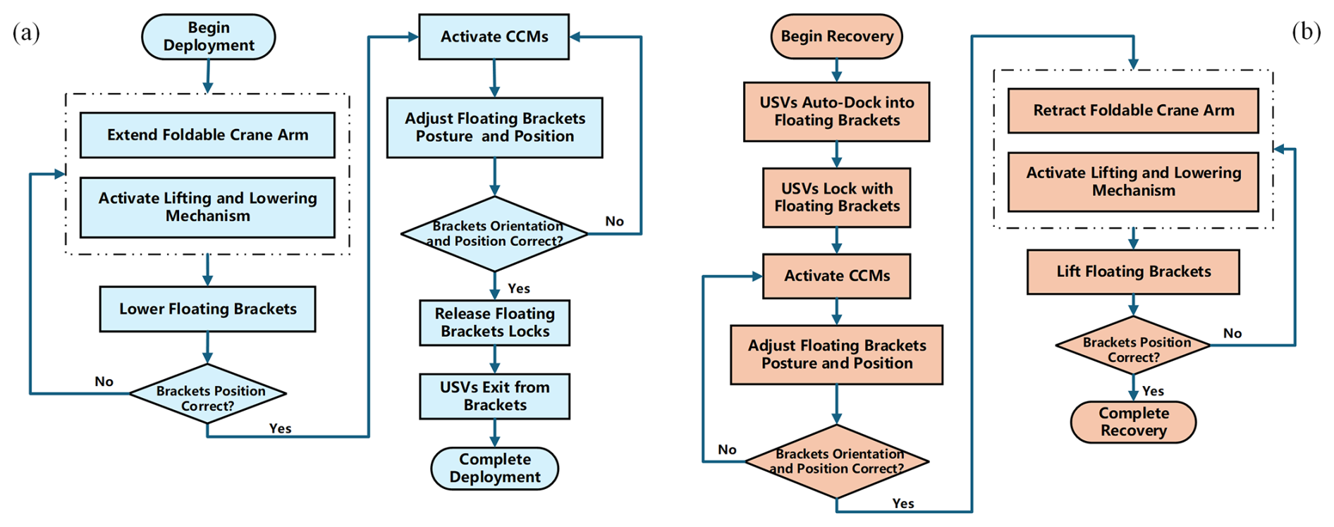
Figure 3Overall control flowchart: (a) launch control flowchart and (b) recovery control flowchart.
The crane arm is the main moving and load-bearing mechanism of the launch and recovery (LAR) system. We aim to design a foldable crane arm for the multi-USV LAR system. In the fully folded configuration, the three floating brackets are arranged in a stepped formation on the mother ship's deck, as illustrated in Fig. 4a. In the deployed configuration, the crane arm extends horizontally, with the three floating brackets positioned outboard of the ship's side, as shown in Fig. 4b.
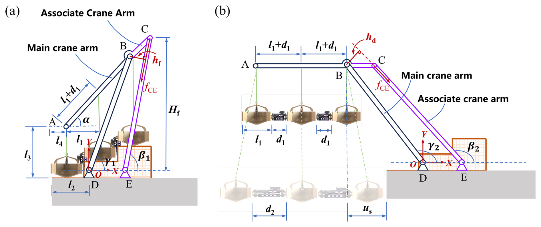
Figure 4Foldable crane arm for three USVs: (a) folded configuration and (b) deployed configuration.
To meet the above requirements, the crane arm is designed to retract and achieve a considerable extension length when deployed. A double rocker mechanism is employed for the crane arm. The crane arm can be divided into two parts: the main crane arm and the associate crane arm. The main crane arm serves as the primary driving and load-bearing component, responsible for driving the extension and retraction of the crane arm. The associate crane arm functions as a secondary component, used to control the deployment angle of the crane arm and provide auxiliary support. In the next subsection, we will examine the geometric dimensions of the foldable crane arm to ensure it meets the required motion criteria.
3.1 Geometric models
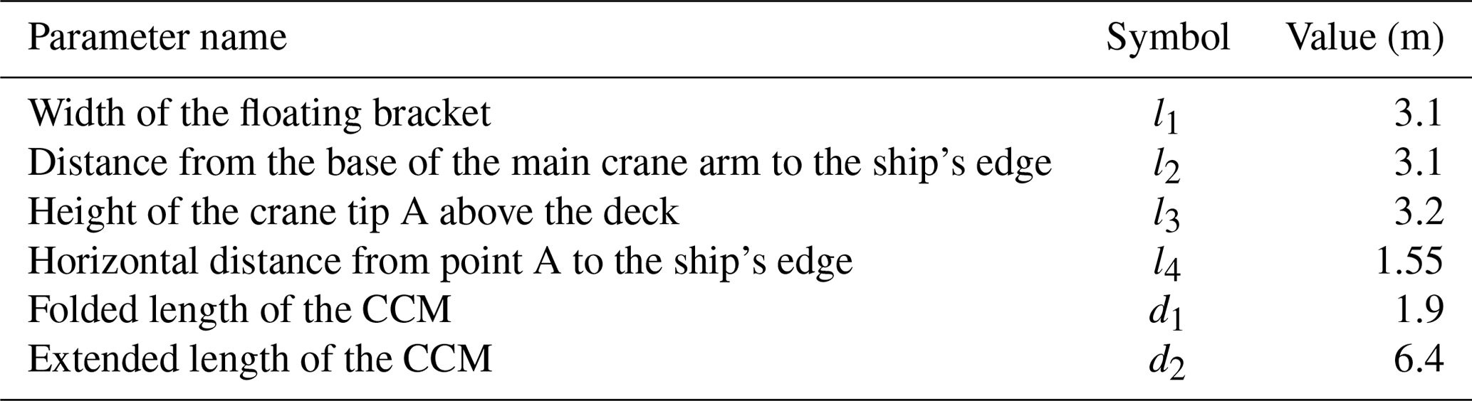
As shown in Fig. 4, set the width of the floating bracket as l1, the contracted length of the CCM as d1, and the extended length of the CCM as d2. The distance between the bottom pivot point D of the main crane arm and the edge of the mother ship is l2. The height of the crane arm's tip from the bottom of the floating bracket is l3, and its distance from the edge of the mother ship is l4. When the floating brackets are in the fully folded configuration, they should be able to rest completely on the deck of the mother ship. To meet this condition, the minimum distance l4 from the tip of the crane arm to the edge of the mother ship should be . When the floating brackets are in the fully deployed configuration, the three floating brackets are in a horizontal position, and the distance between two adjacent suspension points is l1 + d1. The horizontal distance between adjacent suspension points is l1. The length of the connecting rod AB is rAB = 2(l1+d1). Therefore, the angle of the main crane arm AC after being folded is
When deployed, the three floating brackets are positioned outboard of the ship's side. To prevent the floating brackets from colliding with the edge of the mother ship, the minimum distance us between suspension point B and the edge of the ship should be
A coordinate system is established at the bottom pivot point D of the main crane arm. When the mechanism is folded, the coordinates of point A on the main crane arm are ; the coordinates of point B are ; and the coordinates of point C are . From the geometric relationships, it can be determined that
The length of the connecting rod BD and the folding angle γ1 of the main crane arm are given by
When the mechanism is deployed, the deployment angle γ2 of the connecting rod BD in the main crane arm is given by
In the deployed configuration of the main crane arm, the coordinates of point B are , and the coordinates of point C are . Let the length of connecting rod BC be rBC. From the geometric relationships, it can be obtained that
Let the length of connecting rod CE be rCE and the distance between pivot points D and E be uDE. In the folded state, the following relationships are
In the deployed state, the following relationships hold:
For a given uDE, by solving the system of the four equations derived above, the values of rBC, rCE, and β1 and β2 can be obtained, providing the design parameters of the associated crane arm.
3.2 Parameter optimization
When the crane arm is folded, it is preferable for its height to be as low as possible. A lower folded height reduces the center of gravity of the entire LAR system, enhancing safety and minimizing its footprint. As shown in Fig. 4, the height of the folded crane arm can be written as
Meanwhile, as the mechanism transitions from the folded configuration to the deployed configuration, the associate crane rod CE causes the main crane rod AB to rotate from the initial angle α to a horizontal position. The lever arm for this rotational torque depends on the length rBC and the included angle between rods BC and CE. A larger lever arm reduces the tension/compression fCE in rod CE, thereby improving the mechanical performance of the crane arm. When the mechanism is in the folded configuration, the lever arm of rod BC that generates the rotational torque is
We define the ratio φ1 as
If the height of the folded crane arm decreases or the lever arm of rod BC increases, the ratio φ1 becomes smaller.
Similarly, when the mechanism is in the deployed configuration, the lever arm of rod BC is
And the ratio of the height of the folded crane arm to the lever arm of rod BC is
For this deployment and recovery mechanism, we aim to minimize the height of the folded crane arm while maximizing the lever arm of rod BC when fully folded and extended. Therefore, we propose an evaluation function:
A smaller value of φ indicates that the folded height is smaller or the lever arm is larger, resulting in better performance of the foldable crane arm. Assume the constraint parameters of the foldable crane arm as shown in Table 1.
The length of the rod rBC is varied from 0.25 to 7 m, and the variation of the evaluation function φ is shown in Fig. 5.
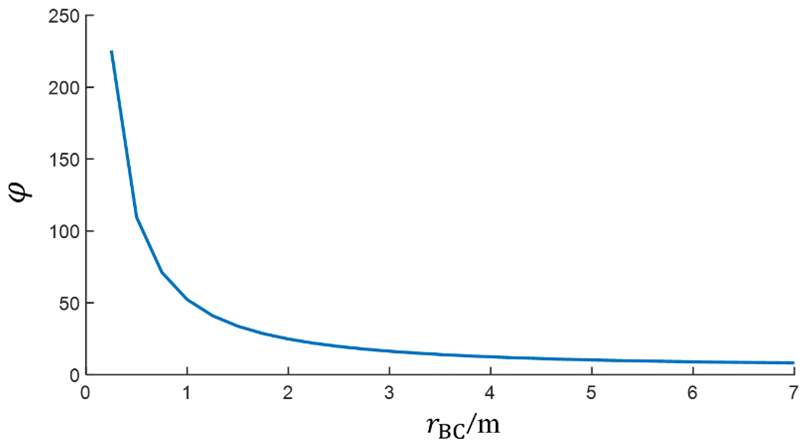
From the evaluation function variation curve, it can be observed that the length of rod rBC approaches 3.5 m, at which point the φ curve becomes nearly horizontal, and the evaluation function value stabilizes at the minimum. In this study, rBC = 3.5 m is selected for the mechanism design, resulting in the following mechanism parameters for the foldable crane arm, as shown below.
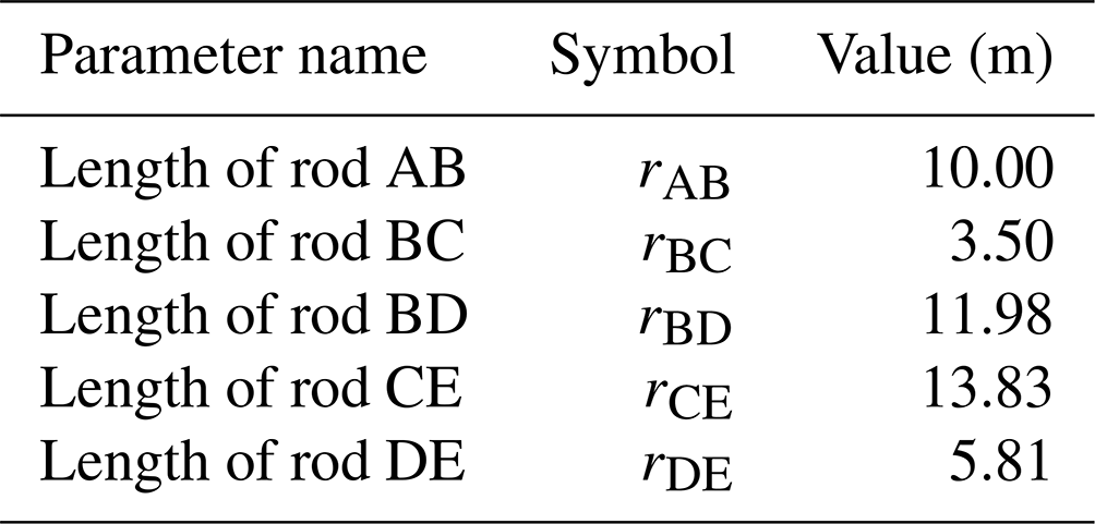
When the mechanism is folded, the angle between the associate crane arm and the ground is β1 = 85.81°. When the mechanism is fully extended, β2 = 145.96°.
After determining the fundamental geometric parameters of the mechanism, we conducted topology optimization design for the key components. Rod ABC serves as the moving link in the double rocker mechanism and also connects three floating brackets, making it a key load-bearing component of the LAR system. To reduce the system's weight, this paper applies a structural topology optimization method to rod ABC. Figure 6a shows the initial model of Rod ABC, which is a solid triangle made of aluminum alloy. After optimization, the results are presented in Fig. 6b. To facilitate manufacturing, we performed post-processing on the shape in Fig. 6b to obtain the shape in Fig. 6c. As can be seen, the shape in Fig. 6c is more regular, meeting engineering requirements and ensuring efficient production. Additionally, the structural weight of the shape in Fig. 6c has been reduced by 35 % compared to the shape in Fig. 6a.
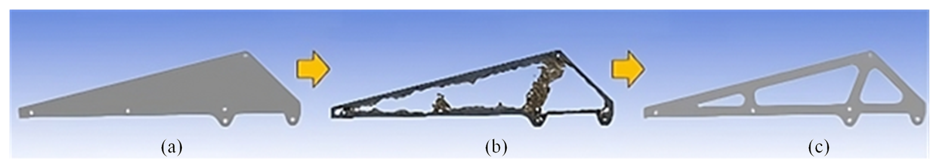
Figure 6Topology optimization for rod ABC: (a) initial shape, (b) topology optimization result, and (c) post-processed result.
Based on the optimized parameters mentioned above, a foldable crane arm was designed for three USVs. The process of the foldable crane arm transitioning from fully folded to fully deployed is shown in Fig. 7.
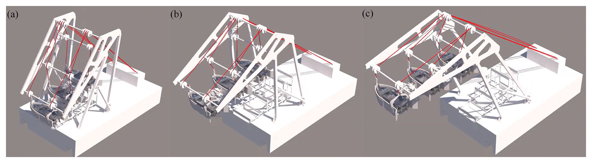
Figure 7Simulation of the motion process of the foldable crane arm: (a) fully folded, (b) extending, and (c) fully deployed.
4.1 Hydrodynamic analysis of multi-floating brackets near the mother ship
During the deployment and recovery processes, multi-floating brackets operate in close proximity to the mother ship. The hydrodynamic interactions between the floating brackets themselves, as well as between the floating brackets and the mother ship, play a critical role in determining the success rate of these operations. To better understand these interactions, we conducted fluid dynamics simulations. Our investigation focused on the hydrodynamic characteristics between the mother ship and the floating brackets, as well as those among the floating brackets, during the deployment of multiple USVs.
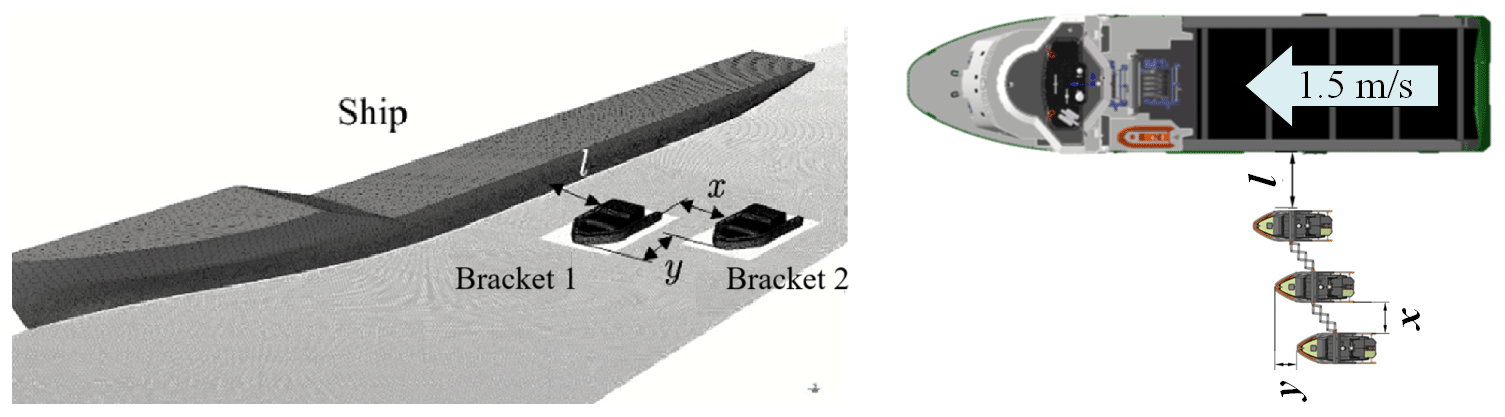
The mother ship is approximately 73 m long, while the floating brackets measure about 7.1 m × 3.1 m, and the uncrewed vessels are roughly 6.7 m × 2.2 m in size. To simplify the model and reduce computational complexity, our study concentrated on the two floating brackets closest to the mother ship. Assuming x represents the lateral distance between two adjacent floating brackets (ranging from 0.5 to 1.5 m), y represents the longitudinal distance between two adjacent floating brackets (ranging from 0 to 2 m). Additionally, the lateral distance between the nearest floating bracket and the mother ship is fixed at 2 m, and the forward velocities of both the mother ship and the floating brackets are 1.5 m s−1. The computational model is as illustrated in the computational model in Fig. 8.
This study investigates the impact of varying x and y on the hydrodynamic characteristics during the launch and recovery of USVs. The velocity distribution of the free-surface flow field is calculated for nine simulation conditions, with the results presented in Fig. 9.
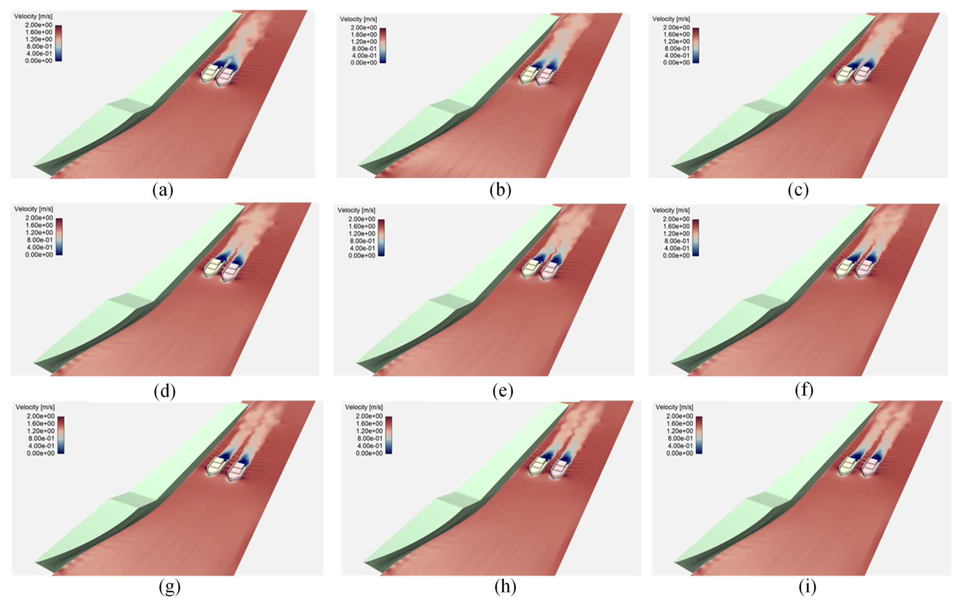
Figure 9Velocity distribution of the flow field under nine simulation conditions: (a) x = 0.5 m, y = 0 m; (b) x = 0.5 m, y = 1 m; (c) x = 0.5 m, y = 2 m; (d) x = 1 m, y = 0 m; (e) x = 1 m, y = 1 m; (f) x = 1 m, y = 2 m; (g) x = 1.5 m, y = 0 m; (h) x = 1.5 m, y = 1 m; and (i) x = 1.5 m, y = 2 m.
The lateral force coefficient (Cy) and yawing moment coefficient (Cm) are calculated based on the aforementioned simulation conditions. As illustrated in Fig. 10, the absolute values of Cy and Cm for bracket 1 and bracket 2 are notably high under the condition x = 0.5 and y = 0. This is attributed to the small values of x and y, which intensify the ship–suction effect.
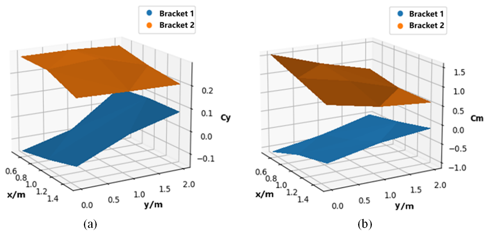
Figure 10Lateral force coefficient and yawing moment coefficient for two floating brackets: (a) lateral force coefficient and (b) yawing moment coefficient.
As x and y increase, the absolute values of Cy and Cm decrease. Notably, when y is approximately 1 m, bracket 1's Cy reaches zero. As y continues to increase, the Cy value for bracket 1 begins to rise in the opposite direction, while bracket 2's Cm continues to decrease. These indicate that increasing the lateral distance between the floating brackets and appropriately adjusting the longitudinal distance can effectively mitigate the mutual interference between the floating brackets during the LAR process.
4.2 Design of CCM with double-layer scissor structure
To achieve lateral and longitudinal distance adjustments between multiple floating brackets, this paper presents the design of a novel CCM. The CCM consists of a double-layer scissor structure and two linear actuators, mounted on the sides of the floating brackets, as shown in Fig. 11.
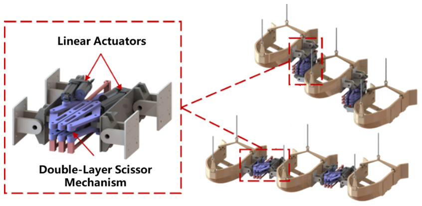
By controlling the extension and retraction of the two linear actuators, the CCM can be driven to move in three directions, as illustrated in Fig. 12a. This mechanism enables three floating brackets to transition from the initial compact configuration to four distinct deployed configurations: linear configuration (LC), parallelogram configuration (PC), V-shaped configuration (VC), and inverted V-shaped configuration (IVC), as shown in Fig. 12b. Enabled by the CCM, the floating brackets can adapt to various configurations, ensuring the safe and efficient launch and recovery of multiple USVs.
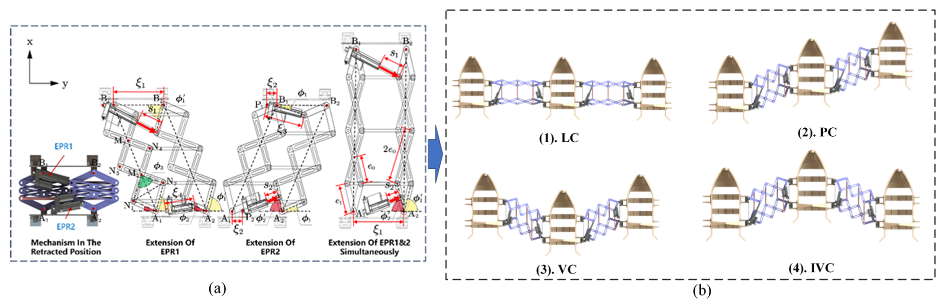
Figure 12Configuring multiple floating brackets for USV launch and recovery: (a) CCM moving in three directions and (b) four distinct deployed configurations.
Compared to single-USV LAR systems, multi-USV LAR systems include several USVs. A suitable control strategy must be implemented to ensure that multiple USVs can autonomously and orderly dock their corresponding floating brackets. This paper presents a novel multi-USV recovery control scheme based on a two-stage partitioned guidance approach.
5.1 Multi-USV recovery control scheme based on two-stage partitioned guidance
During the multi-USV recovery process, the autonomous guidance recovery area is defined as a sectoral region with a 50 m radius and a 60° central angle, centered on three floating brackets: P0, P1, and P2, as illustrated in Fig. 13. This sector is further divided into two distinct regions:
- 1.
The vision-based docking zone is a 10 m radius zone centered on P0, P1, and P2, where vision-based guidance techniques are employed to ensure precise docking of the USVs with their respective floating brackets.
- 2.
The long-range recovery zone is a zone spanning from 10 to 50 m in radius, where GPS positioning, combined with remote control, assists the USVs in approaching the floating brackets effectively.
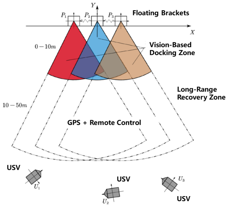
Upon entering the long-range recovery area, the USV maintains its course toward the floating brackets until it reaches the vision-based docking zone. Once within the vision-based docking zone, the USV automatically switches to the visual recognition positioning system and adjusts its heading to align with the corresponding floating bracket.
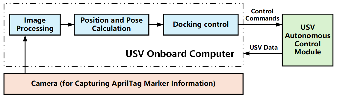
Each USV, labeled as in Fig. 13, is equipped with an onboard computer and a camera for visual tracking of the floating bracket. Similarly, each floating bracket carries a unique docking AprilTag marker, denoted as in Fig. 13, which can be identified by the USV. Using its camera, the USV detects the corresponding AprilTag marker, computes its relative position and orientation, and adjusts its heading to approach the floating bracket.
The onboard computer processes images of the docking marker captured by the camera, calculates the USV's relative position and orientation, and sends control commands to the propulsion controller. The propulsion controller adjusts the differential rotation of the propellers, enabling the USV to track and dock with the corresponding floating bracket. The vision-based docking control process for the USV is illustrated in Fig. 14.
5.2 Vision-based docking method
During the autonomous recovery and docking process of the USV, reliable visual recognition is essential for accurately determining the position and orientation of the floating bracket, ensuring effective docking operations. To achieve this, AprilTags are chosen as the identification markers for the docking process between the USV and the floating bracket. AprilTags use a dictionary encoding system specifically designed to encode small amounts of data, enhancing detection range and positioning accuracy. The primary advantage of AprilTags is their high localization precision. For distances under 10 m, the positioning error can be kept within 10 cm. Therefore, an AprilTag is highly suitable as an identification marker for the USV-floating bracket docking operation.
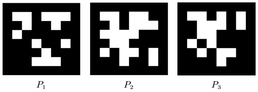
The higher the pixel count of the AprilTag, the more complex the pattern becomes, which reduces the false-detection rate and improves recognition stability. Considering the challenge of adjusting the USV's direction on the water surface, this study selects an AprilTag pattern with 8 × 8 px to meet the required docking accuracy. The three AprilTag markers mounted on the floating bracket are shown in Fig. 15. Each marker is unique, allowing the camera to correctly identify and distinguish between them, thus avoiding confusion or misidentification.
The image recognition algorithm for AprilTag typically follows these steps:
- 1.
The AprilTag image is captured and converted to grayscale to reduce computational complexity.
- 2.
Noise filtering is applied, usually using a Gaussian filter, to enhance image details.
- 3.
The grayscale gradient of the image is calculated, and edge detection techniques are employed to extract the image's edges.
- 4.
Straight edges in the image are fitted using the least-squares method, and closed quadrilateral regions are searched for and detected.
- 5.
The detected quadrilateral regions are then processed through image binarization, where pixel values are converted to either 0 or 1 based on specific rules, resulting in a binary image.
- 6.
The pixel points of the quadrilateral are encoded and matched against the system's preset IDs to verify whether the detected pattern corresponds to the selected AprilTag marker.
Using the above visual recognition method, the AprilTag marker and its feature points can be obtained. These feature points are used for position and posture estimation, providing the relative position and posture information of the USV with respect to the marker. In this study, a monocular camera is mounted on the USV, and the Perspective-n-Point (PnP) method (refer to Qiao et al., 2023) is employed to determine the position and posture of the USV.
After obtaining the USV's position and posture with respect to the floating bracket, the USV can autonomously navigate into the bracket using autonomous control. The USV is equipped with a dual-propeller system. For this type of USV, this section derives the kinematic model and PID control model to achieve autonomous return navigation.
6.1 Kinematic and dynamic of the USV
In this paper, the USV is equipped with a dual-propeller system. The position and motion state of the USV are described using a combination of the ground coordinate system and the USV coordinate system, as shown in Fig. 16.
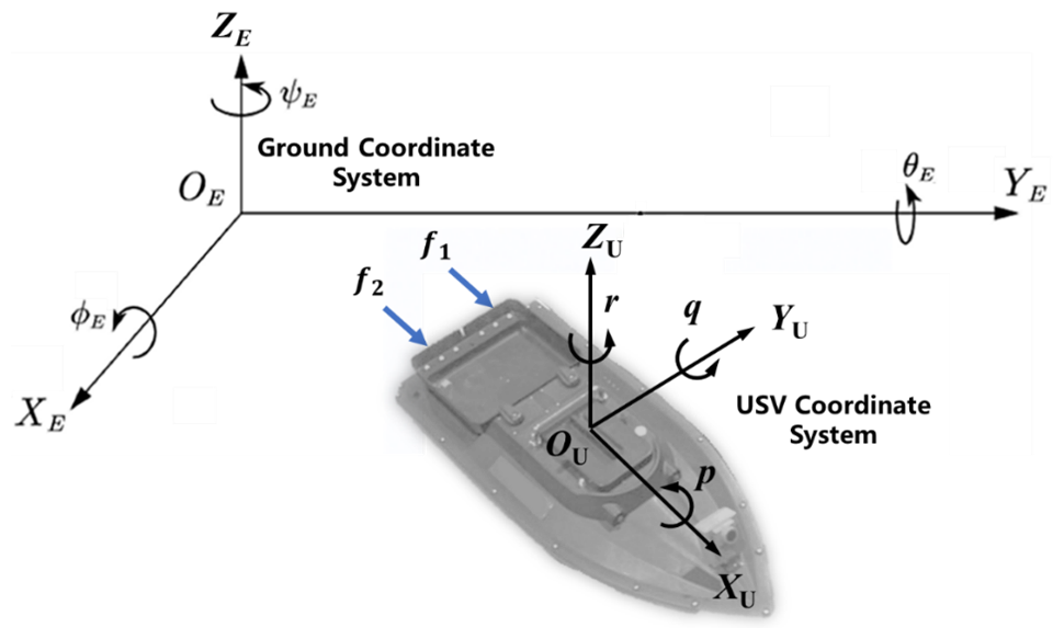
In the ground coordinate system, the position and the orientation of the USV are represented by the vector
where x, y, and z represent the position of the USV in the longitudinal, lateral, and vertical directions of the ground coordinate system, respectively; ϕ, θ, and ψ represent the roll angle, pitch angle, and yaw angle of the USV in the ground coordinate system, respectively.
In the USV coordinate system, the velocity of the USV is represented by the vector
where u, v, and ω represent the surge, sway, and heave velocities of the USV, respectively; p, q, and r represent the roll, pitch, and yaw angular velocities of the USV, respectively.
Therefore, the kinematic equations of the USV are
where J(η) is invertible transformation matrix between the ground coordinate and the USV coordinate. Since this paper primarily focuses on the autonomous navigation of underactuated USVs on a horizontal plane, it is unnecessary to consider the full six-degrees-of-freedom model. Instead, only three degrees of freedom on the horizontal plane – surge, sway, and yaw – are retained, leading to a simplified horizontal plane kinematic model.
where = and .
In the dynamic modeling, this paper assumes that the resistance acting on the USV is linearly proportional to its velocity. Therefore, the dynamics of the USV can be described by the following equations.
Here, M represents the inertia matrix of the USV; D(v) is the hydrodynamic damping matrix; C(v) denotes the centripetal and Coriolis force coefficient matrix; τ is the thrust and moment vector of the USV; and w represents the environmental disturbance force/moment vector. This paper considers a USV equipped with dual propellers, with its dynamic control input given by
where f1 represents the force generated by the left propeller, f2 represents the force generated by the right propeller, and B is the width between the two propellers. Since the thrust generated by the propellers is related to the rotational speed of the propellers, the classical thrust model of the propeller can be adopted in this paper:
where fi is thrust, ρ is fluid density, ni is propeller rotational speed, D is propeller diameter, and Ki is thrust coefficient.
6.2 PID controller
PID control is the most widely used control algorithm in practical engineering applications. Based on its output type, it can be classified into position-based PID and incremental PID. Since USV heading control requires real-time adjustments, this paper uses an incremental PID controller to achieve heading control. Incremental PID does not require knowledge of the current position; it only calculates the change in the control action based on the deviation variation, and its formula is
Compared to position-based PID, incremental PID only considers the deviation values from the last three sampling periods. When a large error occurs due to a brief system failure, the incremental PID controller can eliminate the impact of the error within three sampling periods, ensuring stable and reliable operation of the USV heading control system.
The heading deviation Δψ of the USV is used as the input to the PID controller. The control signal calculated by the PID controller is mapped into pulse-width modulation signals for controlling the electronic speed regulators of the left and right propellers. By adjusting the differential rotation speed of the propellers, precise heading control of the USV is achieved. The core of this control system is the PID heading controller, and its control process is shown in Fig. 17.
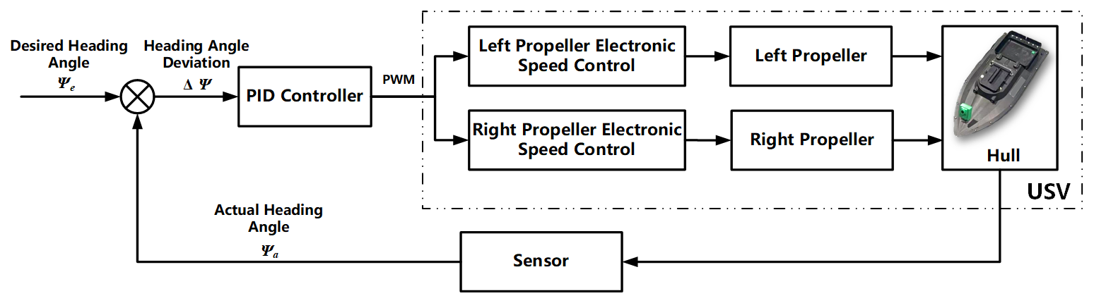
If the current heading of the USV has a large deviation from the desired heading Δψ (for the method used to solve the desired heading, refer to Wang and Han, 2016; Dong et al., 2020), the PID heading control will generate a deviation control value. By adjusting the differential speed of the two propellers, the USV will quickly align with the corresponding floating bracket. In this process, the current heading angle of the USV will gradually approach the desired heading angle, and the heading deviation Δψ will decrease gradually. Through continuous adjustment, as long as the heading deviation Δψ exists, a corresponding control action will be generated to reduce the deviation, until the heading deviation Δψ approaches zero, enabling the USV to continuously align with the floating bracket.
7.1 Prototype
7.1.1 Prototype of a crane-like LAR system for multiple USVs
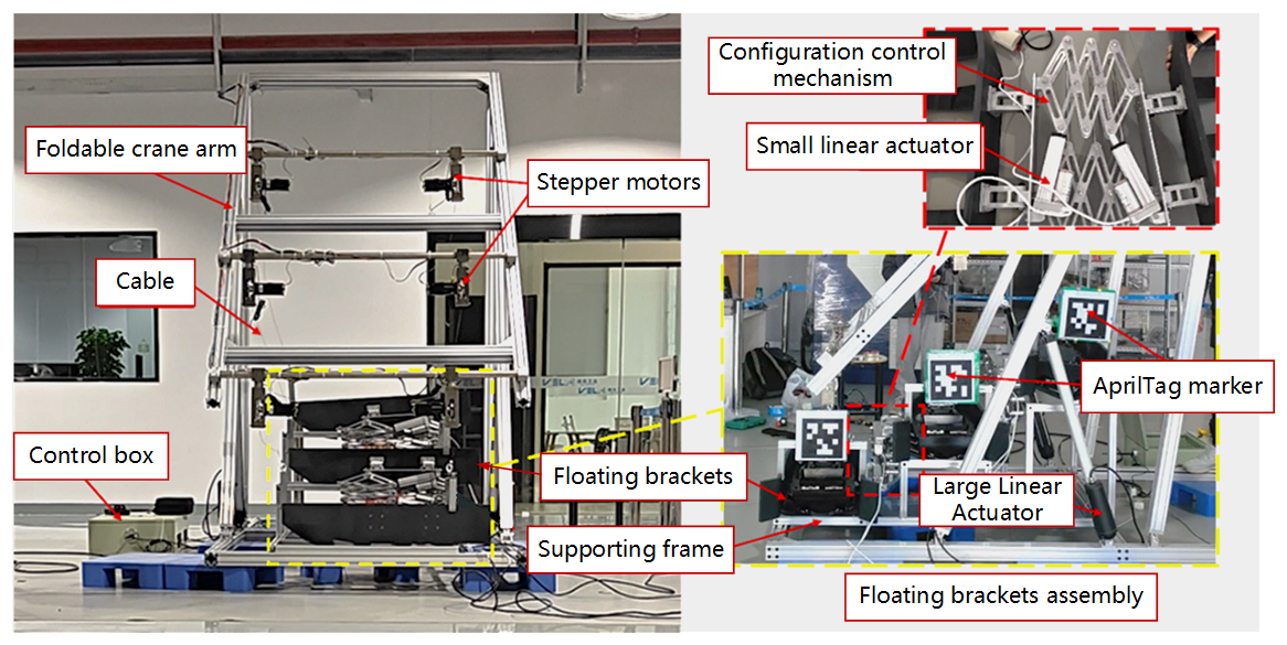
A scaled-down prototype of a crane-like LAR system for multiple USVs was designed and manufactured, with a scale ratio of 1:5. The prototype is made of aluminum, and the control box utilizes an STM32 control board. The crane's deployment and retraction are driven by linear actuators, while the stepper motors drive the three docking floats to move up or down. The prototype is shown in Fig. 18.
During operation, the scaled-down prototype's foldable crane arm extends through the linear actuators, transitioning from a retracted state to a fully deployed state, enabling the deployment of USVs, as shown in Fig. 19a–c. Subsequently, the linear actuators retract, causing the foldable crane arm to move from the fully deployed state back to the retracted state, facilitating the recovery of USVs. The motion process is illustrated in Fig. 19d–e.
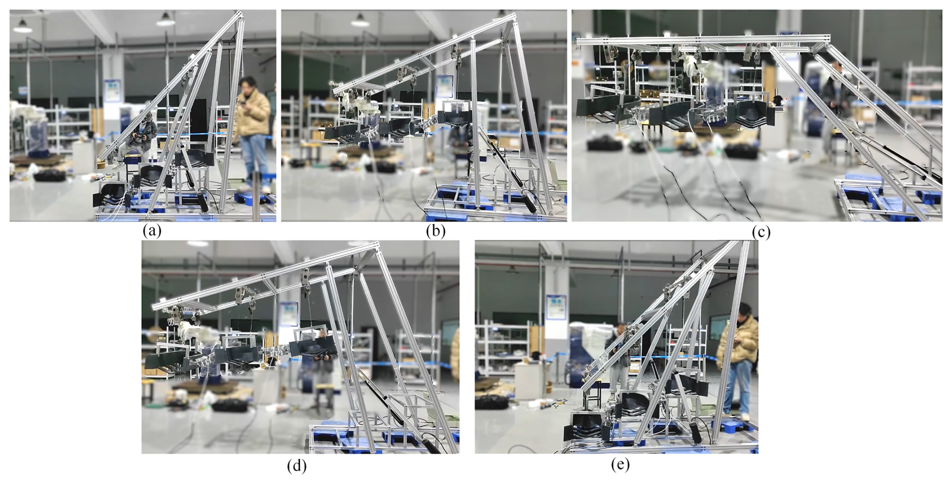
Figure 19Motion of the prototype's foldable crane arm: (a) retracted state, (b) deploying, (c) fully deployed state, (d) retracting, and (e) back to retracted state.
In the initial retracted state of the floating bracket assembly, the distance between the floating brackets is 0.4 m, as shown in Fig. 20a. By controlling the four linear actuators of CCM, the system can smoothly transition among four configurations: linear configuration (LC), parallelogram configuration (PC), V-shaped configuration (VC), and inverted V-shaped configuration (IVC). The maximum lateral extension distance of the two floating brackets is 1 m, with a longitudinal distance of 0 between the brackets in this configuration, as shown in Fig. 20b. When the floating brackets are configured in parallelogram extension, V-shaped, or inverted V-shaped, the maximum lateral extension distance is 0.7 m, and the maximum longitudinal extension distance is 0.25 m, as illustrated in Fig. 20c, d, and e. These different configurations correspond to various deployment and recovery states of USVs, enabling the LAR system to flexibly and accurately perform operations under different circumstances.
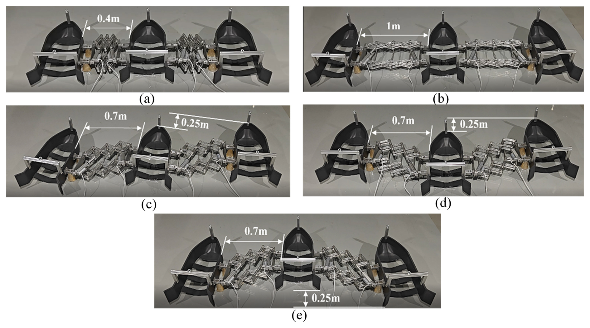
Figure 20Motion of the CCM: (a) initial retracted state, (b) LC, (c) PC, (d) VC, and (e) IVC.
7.1.2 Dual-motor dual-propeller USV prototype
The USV prototype used in this study has dimensions of 660 × 300 × 170 mm. The internal hardware layout of the prototype is shown in Fig. 21. The USV prototype is powered by a dual-motor dual-propeller propulsion system.
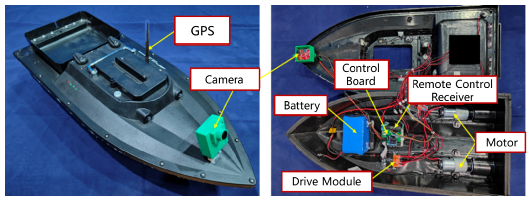
The main control board of the USV prototype adopts an STM32F405RG circuit board. It features a 168 MHz main frequency and an integrated IMU chip, the MPU6050. A camera is installed at the bow of the USV. This camera has a resolution of 5 MP and an effective recognition distance of approximately 7 m. When the USV camera detects an AprilTag marker, it calculates the position and posture information of the marker relative to the camera. After receiving the position and posture data, the main control board computes the voltage difference for the two propulsion motors at the stern using a control model and converts this into corresponding control commands, which are then transmitted to the motor drive module. The motor drive module, upon receiving the commands, drives the motors to perform differential rotation. This enables the USV to correct its heading and ensures that it always moves toward the direction of the corresponding floating bracket.
7.2 Experimental validation
The scaled-down prototype of the multi-USV LAR system conducted the lake tests. The tests focused on evaluating the system's functions and performance. This included verifying deployment and recovery of the LAR system and the departure and docking of the USVs with the floating brackets.
Firstly, the deployment and recovery of the prototype were verified. The prototype was initially set up on the shore in the folded state of the crane arm, as shown in Fig. 22a. Once the system was beginning to deploy, the crane arm gradually unfolded until the arm became parallel to the water surface, as illustrated in Fig. 22b and c. During this process, the cables and CCM extended in sync with the unfolding speed of the crane arm, controlling the floating brackets to transition from their folded state to the linear configuration. Ultimately, the floating brackets were successfully deployed, as shown in Fig. 22d. After the floating brackets were deployed to the water surface, three USVs sailed out and departed from their respective floating brackets, as shown in Fig. 22e and f. The entire deployment operation was smooth and stable, with all components working in coordinated harmony. The experimental results aligned well with the design expectations.
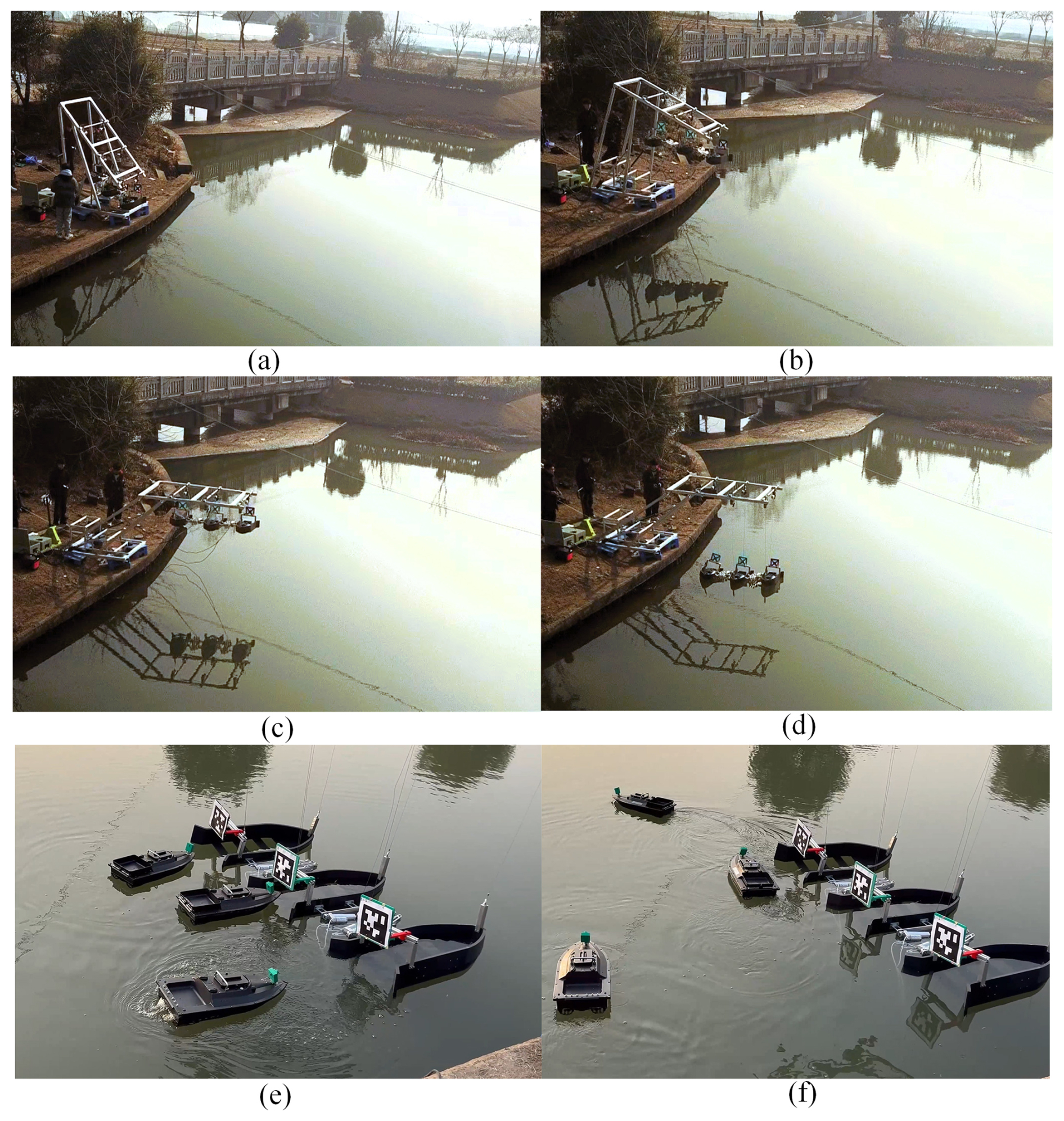
Figure 22Deployment of multiple USVs: (a) folded LAR system, (b) deploying, (c) fully deployed, (d) lowing floating brackets, (e) USVs sailing out, and (f) USVs departing.
When the USVs were required for recovery, their control mode was switched to autorecovery navigation. The USV then gradually approached the vision-based docking area. Once it entered into the vision-based docking area, the control mode was switched to vision-based autonomous guidance. The USV's camera system was activated to identify the corresponding markers. Upon successful recognition, the USV adjusted its heading accordingly and completed the docking and recovery process for all three vehicles, as illustrated in Fig. 23a, b, and c.
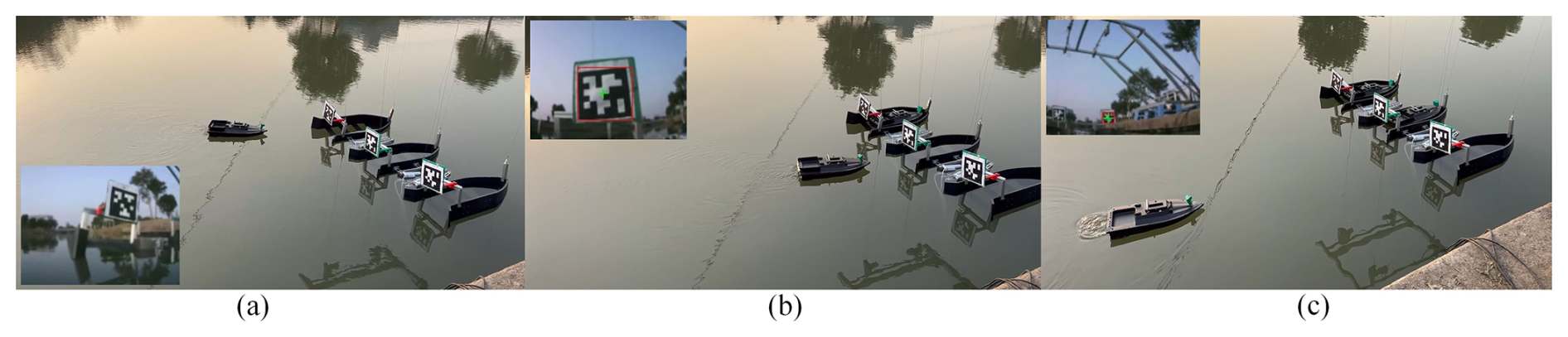
Figure 23Autonomous guidance and docking of USVs: (a) USV 1 autonomous docking, (b) USV 2 autonomous docking, and (c) USV 3 autonomous docking.
Once all three USVs entered their respective floating brackets, the prototype system was activated. Six cables were simultaneously retracted to lift the floating brackets, as depicted in Fig. 24a. Until the floating brackets were raised back to the recovery position, as shown in Fig. 24b, the crane arm began folding gradually, as illustrated in Fig. 24c. Finally, the cables were lowered to put the floating brackets onto the support frame. The recovery process for multiple USVs was completed, as shown in Fig. 24d. The experimental results demonstrated that the entire operation was smooth and stable, successfully recovering all three USVs. The results aligned well with the design expectations.
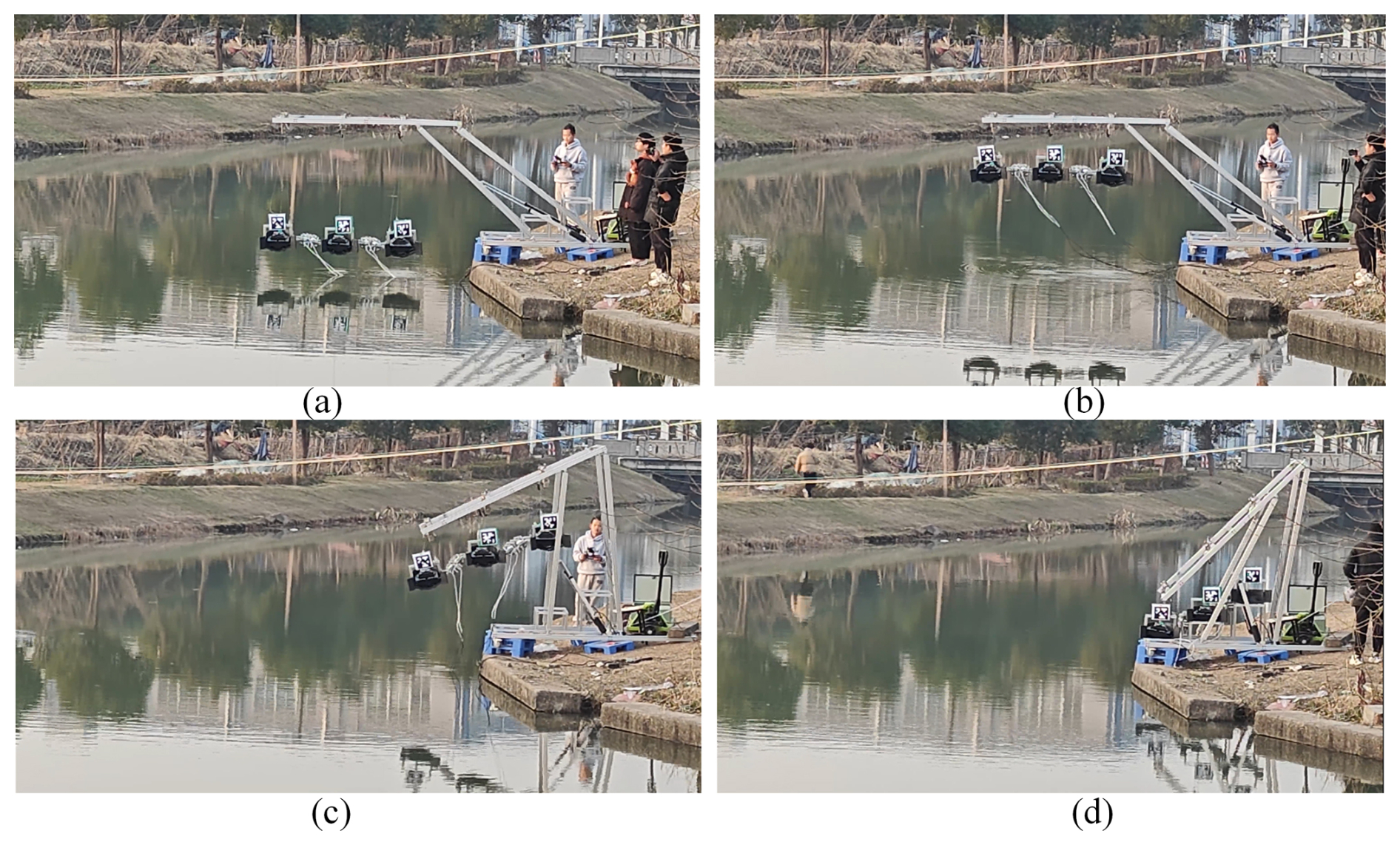
Figure 24Recovery of multiple USVs: (a) floating brackets lifted out of the water, (b) brackets to the recovery position, (c) crane arm folding gradually, and (d) recovery process completed.
This paper proposes a novel crane-like LAR system capable of deploying and recovering multiple USVs. The system consists of several key components, including a foldable crane arm, three floating brackets, two configuration control mechanisms(CCMs), and a lifting and lowering mechanism. The novel foldable crane arm for three USVs is designed, and its optimized parameters are obtained. It offers compactness, a large extension range, and smooth motion. Additionally, the fluid dynamics of the multi-floating brackets near the mother ship are simulated. The simulation results indicate that increasing the lateral distance and appropriately adjusting the longitudinal distance between the floating brackets can effectively reduce mutual interference during the LAR process. Based on these findings, a CCM, consisting of a double-layer scissor structure and two linear actuators, is designed and mounted on the sides of the floating brackets. The CCMs enable adjustments to the lateral and longitudinal distances between multiple floating brackets, minimizing flow field disturbances. To ensure orderly entry of the USVs into their respective floating brackets, an autonomous docking control scheme for multiple USVs is proposed, and a visual-based docking method is investigated. Finally, a prototype was developed, and comprehensive experiments demonstrated that the system successfully recovers all three USVs with a smooth and stable motion. This research presents a novel solution for the reliable deployment and recovery of multiple USVs from the mother ship.
The code represents the collective research achievements of multiple members of our research team and has not been publicly released online. However, the software code used in this study can be obtained from the corresponding author (yiyangshu@t.shu.edu.cn) upon reasonable request.
The research data in this article have not been publicly released and reflect the collective work of the research team. Following discussions among the authors, the data will not be openly shared at this time but may be made available from the corresponding author (yiyangshu@t.shu.edu.cn) upon reasonable request.
All authors contributed to the study of the crane-like launch and recovery system for multiple USVs. DJZ wrote the manuscript and conducted experiments; XHX developed the autonomous control algorithms for USVs; GL designed and analyzed the mechanisms; CXL provided the hydrodynamic analysis; and YY contributed to the conceptualization, control strategy, and supervision.
The contact author has declared that none of the authors has any competing interests.
Publisher's note: Copernicus Publications remains neutral with regard to jurisdictional claims made in the text, published maps, institutional affiliations, or any other geographical representation in this paper. While Copernicus Publications makes every effort to include appropriate place names, the final responsibility lies with the authors.
The authors gratefully acknowledge the financial support of the National Natural Science Foundation of China and the Natural Science Foundation of Shanghai Municipality.
This research was supported by the National Natural Science Foundation of China (grant no. 52475023) and Natural Science Foundation of Shanghai Municipality (grant no. 24ZR1424300).
This paper was edited by Wuxiang Zhang and reviewed by two anonymous referees.
Bai, X., Li, B., Xu, X., and Xiao, Y.: A review of current research and advances in unmanned surface vehicles, J. Marine Sci. Appl., 21, 47–58, https://doi.org/10.1007/s11804-022-00276-9, 2022.
Chen, J., Yang, Y., Jiang, X., He, X., Xie, S., Peng, Y., ang Qu, D.: A Launch and Recovery System for Unmanned Surface Vehicle Based on Floating Bracket, in: Intelligent Robotics and Applications: 12th International Conference, ICIRA 2019, Shenyang, China, 8–11 August 2019, Proceedings, Part II Springer International Publishing, 12, 215–223, https://doi.org/10.1007/978-3-030-27532-7_19, 2019.
Chen, Y., Ma, L., Duan, W., and Liu, P.: Experimental study on coupled motions of mother ship launching and recovering of human-occupied vehicle in regular waves, J. Marine Sci. Appl., 19, 53–63, https://doi.org/10.1007/s11804-019-00114-5, 2020.
Dong, H., Huang, H., and Zhuang, Y.: Heading angle controller design of usv based on improved sliding mode active disturbance rejection control, in: 2020 Chinese Automation Congress (CAC), Shanghai, China, 6–8 November 2020, IEEE, 3547–3551, https://doi.org/10.1109/CAC51589.2020.9326809, 2020.
Dong, X., Gao, H., and Shang, L.: Analysis of Key Technologies for Unmanned Surface Vessels (USV), in: 2023 2nd International Symposium on Control Engineering and Robotics (ISCER), Hangzhou, China, 17–19 February 2023, IEEE, 158–164, https://doi.org/10.1109/ISCER58777.2023.00034, 2023.
Er, M. J., Ma, C., Liu, T., and Gong, H.: Intelligent motion control of unmanned surface vehicles: A critical review, Ocean Eng., 280, 114562, https://doi.org/10.1016/j.oceaneng.2023.114562, 2023.
Jorge, V. A., Granada, R., Maidana, R. G., Jurak, D. A., Heck, G., Negreiros, A. P. F., dos Santos, D. H., Gonçalves, L. M., and Amory, A. M.: A survey on unmanned surface vehicles for disaster robotics: Main challenges and directions, Sensors, 19, 702, https://doi.org/10.3390/s19030702, 2019.
Kong, D., Yang, S., Yang, L., and Xiang, X.: Design of unmanned surface vehicle docking system based on multi-source observation, Chinese Journal of Ship Research, 19, 214–222, https://doi.org/10.19693/j.issn.1673-3185.03407, 2024 (in Chinese and English).
Kouriampalis, N., Pawling, R. J., and Andrews, D. J.: Modelling the operational effects of deploying and retrieving a fleet of uninhabited vehicles on the design of dedicated naval surface ships, Ocean Eng., 219, 108274, https://doi.org/10.1016/j.oceaneng.2020.108274, 2021.
Li, Y., Jiang, Y., Cao, J., Wang, B., and Li, Y.: AUV docking experiments based on vision positioning using two cameras, Ocean Eng., 110, 163–173, https://doi.org/10.1016/j.oceaneng.2015.10.015, 2015.
Liu, Z., Zhang, Y., Yu, X., and Yuan, C.: Unmanned surface vehicles: An overview of developments and challenges, Annu. Rev. Control, 41, 71–93, https://doi.org/10.1016/j.arcontrol.2016.04.018, 2016.
Pu, H., Liu, Y., Luo, J., Xie, S., Peng, Y., Yang, Y., Yang, Y., Li, X., Su, Z., Gao, S., Shao, W., Zhu, C., Ke, J., Cui, J., and Qu, D.: Development of an unmanned surface vehicle for the emergency response mission of the 'Sanchi' oil tanker collision and explosion accident, Appl. Sci., 10, 2704, https://doi.org/10.3390/app10082704, 2020.
Qiao, R., Xu, G., Wang, P., Cheng, Y., and Dong, W.: An Accurate, Efficient, and Stable Perspective-n-Point Algorithm in 3D Space, Appl. Sci., 13, 1111, https://doi.org/10.3390/app13021111, 2023.
RC Dock Engineering BV: https://rcdock.com/usv-lar-systems, last access: 24 December 2024.
Rout, V., Vile, C., Edwards, C., Belmont, M. J., Li, G., and Taunton, D.: Control of the launch and recovery of small boats to a mothership in high sea states using sliding mode methods, Control Eng. Pract., 146, 105866, https://doi.org/10.1016/j.conengprac.2024.105866, 2024.
Sealartec: https://sealartec.com/2024/01/29/quantum-change-in-launch-and-recovery-operations/, last access: 24 December 2024.
Wang, H., Xiang, G., Xiang, X., and Ahmed, F.: Motion characteristics and T-foil based optimization of marine towed-cage in swell, Appl. Ocean Res., 147, 103992, https://doi.org/10.1016/j.apor.2024.103992, 2024.
Wang, Y. and Han, Q.: Network-based heading control and rudder oscillation reduction for unmanned surface vehicles, IEEE T Contr. Syst. T., 25, 1609–1620, https://doi.org/10.1109/TCST.2016.2617321, 2016.
Yang, Y., Pan, P., Jiang, X., Zheng, S., Zhao, Y., Yang, Y., Zhong, S., and Peng, Y.: An Attitude Prediction Method for Autonomous Recovery Operation of Unmanned Surface Vehicle, Sensors, 20, 5662, https://doi.org/10.3390/s20195662, 2020.
Yu, W., Wang, J., Tang, G., Li, M., and Qiao, Y.: Dual-attention-based optical terminal guidance for the recovery of unmanned surface vehicles, Ocean Eng., 239, 109852, https://doi.org/10.1016/j.oceaneng.2021.109852, 2021.
Zhang, X., Liu, S., Liu, Y., Hu, X., and Gao, C.: Review on development trend of launch and recovery technology for USV, Chinese Journal of Ship Research, 13, 50–57, https://doi.org/10.19693/j.issn.1673-3185.01258, 2018.
Zhou, L., Ye, X., Huang, Z., Xie, P., Song, Z., and Tong, Y.: An improved genetic algorithm for the recovery system of USVs based on stern ramp considering the influence of currents, Sensors, 23, 8075, https://doi.org/10.3390/s23198075, 2023.
- Abstract
- Introduction
- Concept of a crane-like LAR mechanism for three USVs
- Design of a foldable crane arm for three USVs
- Design of configuration control mechanism
- Autonomous docking control scheme for multiple USVs during the recovery procedure
- Autonomous control for the USV
- Prototype and experimental validation
- Conclusion
- Code availability
- Data availability
- Author contributions
- Competing interests
- Disclaimer
- Acknowledgements
- Financial support
- Review statement
- References