the Creative Commons Attribution 4.0 License.
the Creative Commons Attribution 4.0 License.
Application of three-dimensional (3D) hand–eye calibration of industrial robot in laser cladding repair for drilling bit
Jian Wang
Zongjian Mo
Juezhe Wang
Wanghua Pan
In this paper, an entire process of laser cladding repair for damaged polycrystalline diamond compact (PDC) bits of high value based on a dual-robot system is proposed. First, the KUKA-KR20 industrial robot, along with a structural light three-dimensional (3D) scanner, is used to inspect the damaged bit, with point cloud data exported, and then the data are converted to the stereolithography (STL) file format in Geometric Studio, with the damaged region of the bit obtained after comparison with the standard model. Second, the KUKA-KR60 industrial robot holding a laser head is driven to realize cladding. In order to apply the information captured by the camera of the scanner to the laser cladding robot, a novel calibration, i.e., the three-point method for the dual-robot system, is proposed to transform the damaged region of the bit in the camera coordinate system to that in the cladding robot coordinate system, and then an upper computer program is developed to plan the cladding path for the laser head and to send the path to the KUKA-KR60 robot to complete cladding repair. Finally, a real experiment is carried out, which verifies that the dual-robot system has good flexibility and can be widely applied to different types of part repair with different types of blocky-surface damage.
- Article
(7312 KB) - Full-text XML
- BibTeX
- EndNote
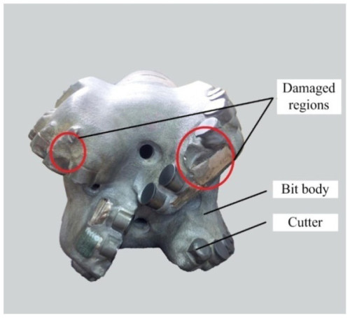
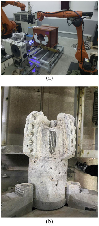
The polycrystalline diamond compact (PDC) bit, which is a kind of integrated bit, has better performance in strength, wear resistance, and impact resistance than that of other types of bits, and it was regarded as one of the newest technologies in the drilling industry in the 1980s. More than 100 000 PDC bits are used in oilfield drilling, mineral exploitation, geothermal well, and other projects every year in China. However, bits in the bottom hole can be damaged by erosion, chemical corrosion, and other factors caused by bad working environments or high-strength working conditions (shown in Fig. 1). So, the bits are the most important high-value consumables in the whole drilling industry. According to the long-term repair experience, the wear types of PDC bits can be roughly divided into compact wear, slight body wear, severe body wear, and scrap. The performance of the damaged bits with compact wear or slight body wear can be recovered well after repair with low cost, while the cost of repair for damaged bits with severe body wear is high, and the scrapped bits cannot be repaired at all. Fortunately, most of the bit wears fall into the former two categories, which makes the repair of bits have great economic and social benefits.
There are still many problems in traditional bit-repair technologies, such as the use of arc welding. In the repairing process of the bit, arc welding causes the temperature of the local area of the bit to be too high, resulting in stress and affecting the service life of the bit. Furthermore, the combination of the re-welded hardened layer and the old one is not strong enough, which easily causes re-welded hardened layers to fall off and to reduce the bit footage.
Laser cladding (Vilar, 1999), which can be used in the bit-repair process to overcome those defects caused by arc welding, is a material additive manufacturing technology that uses a high-energy laser beam emitted from a laser transmitter to heat the substrate and the coating powder sprayed on the surface of the substrate at the same time so that the powder and the substrate complete metallurgical bonding, and the cladding coating is finally formed on the surface of the substrate.
Because the surface repaired by the laser cladding process shows better performance in wear resistance, corrosion resistance, heat resistance, and other aspects when used on the substrate than those by other remanufacturing processes, such as welding repair technology, thermal spraying and thermal-spray welding repair technology, and brush plating repair technology, the laser cladding process has been receiving increasing attention from the remanufacturing industry and is widely used in repairing the hard facing of turbine blades (Gao et al., 2005, 2008; Huang et al., 2020; Rong et al., 2014; Xu et al., 2017; Zheng et al., 2019b, 2017) and forging die (Görgl and Brandstätter, 2016; Li et al., 2014; Luo et al., 2017) as well as in various material processing industries for complex curved surface generation (Liu, 2013; Liu et al., 2021; Wang et al., 2018; Zhu et al., 2017) and repairs of scratches on rail surfaces (Guo et al., 2020), artificial joints in medical treatment (Zhu et al., 2020), broken gear (Zhu et al., 2020), worn-out sprockets (Liu et al., 2017), and so on. So, after cladding, the PDC bit is not easy to deform, the structure is compact, and the bonding strength is high, which are major advantages compared with the traditional processing methods (Vilar, 1999).
The repairing process based on laser cladding mainly includes two key steps: inspection and cladding. Although there is little literature on PDC bit repair, repairing projects of other products can be learned from because the whole repair process is universal. The purpose of inspection is to obtain the information on the damaged part that is to be repaired, and with the development of optical technology, non-contact measuring equipment, such as the structural light three-dimensional (3D) scanner (Gao et al., 2005, 2008; Huang et al., 2020; Liu et al., 2017; Rong et al., 2014), stereo vision sensor (Luo et al., 2017; Zhang et al., 2019), and 3D laser vision (Davis and Shi, 2011; Guo et al., 2020; Liu, 2013; Um et al., 2017), becomes the first choice for inspection. The 3D point cloud of the damaged part can then be obtained using the mentioned non-contact measurements with a stereolithography (STL) file (Zheng et al., 2019b) being exported in most cases, and one can compare the exported STL file, which approximates the real scanned damaged part via a lot of triangular patches, with the standard STL file of the same part to obtain the damaged region that needs repairing by a simple collection operation (Gao et al., 2005; Guo et al., 2020; Huang et al., 2020; Liu et al., 2017; Zhang et al., 2019; Zhu et al., 2020). Um et al. (2017) also tried to obtain the damaged region of a die in the STEP file format in the cladding repairing process, and they point out that the representation of solid models based on STEP keeps the error lower during geometric reasoning than based on STL, though the STL format is the mainstream method. There are several tasks, such as calibration, path planning of the cladding head, robot program generation, and reprocessing, to be done in cladding step, and among them, path planning is the most concerning problem according to the literature. Zheng et al. (2017, 2019a) studied the path planning for laser cladding on complex spatial surfaces, in which they optimize the model parameters affecting the model error according to the particle swarm optimization (PSO) method, but they obtain the STL data directly from the CAD model without initiating the inspection step. Similarly, Liu et al. (2021) obtain the optimal cladding path of complex surface by adjusting the distance between adjacent section points, also without the inspection step. Li et al. (2020) plan a path for laser cladding on an artificial joint surface through the arch height error method without implementing an inspection step. Liu (2013) uses a 3D laser scanner to inspect an entire spatial curved surface and obtains the path for laser cladding via the slicing method according to the STL file. In order to express the curved surface accurately, Wang et al. (2018) export the non-uniform rational B-spline (NURBS) surface from point cloud data inspected by a 3D scanner and then obtain the optimal path by the arch height error method. On the subject of path planning for laser cladding on the spatial curved surface, the existing works are more like 3D printing rather than repair whether or not the inspection step is carried out at first because the damaged regions appear locally rather than the entire surface, which means it is necessary to locate the damaged region or calibrate the 3D scanner. Although Liu et al. (2021) provide the transformation between the 3D scanner coordinate system and the robot base coordinate system, such a transformation is not calibrated, does not appear in the following text, and varies with the changes in the posture of the robot, so it is not suitable for locating damages at all. On the subject of path planning for laser cladding on blocky-surface damage, Zhu et al. (2020) and Zhang et al. (2019) obtain the layer-by-layer cladding path by the slicing method for the complex component, and Montoya-Zapata et al. (2021) discuss the influences of a different path order on the performance of laser cladding. However, the common defect is that the calibration between the scanner and the base coordinate system, which is the key to showing the position of the damaged region of the part for the laser cladding head automatically and to determining the accuracy of the repair, does not appear in the existing literature. It is worth noting that deep learning methods are being increasingly applied in some robot path-planning techniques. Diao et al. (2024) propose a robot path-planning method based on graph neural networks to solve the obstacle problem of robots in high-dimensional state space, and Chen et al. (2024) use convolutional neural networks (CNNs) for semantic segmentation of images to identify different terrain types for hexapod walking robots to plan their gait and path in the multi-terrain environment of Mars. In addition, Li et al. (2022) propose an open-loop and closed-loop iterative learning control for the trajectory tracking of high-speed 4-degree-of-freedom parallel robots. The next task is to generate an offline program according to the planned path of the cladding head either for a computer numerical control (CNC; Um et al., 2017) machine or for a robot (Liu, 2013). And nowadays, the laser cladding robot is the leading form of part repair where the accuracy requirement is not so high, but the types of damages of the part are abundant. Li et al. (2014) use specific software to quickly generate an offline program for the KUKA robot, though the generated program is not common for other robots. The surface quality of the repaired part after cladding is always very poor, so a reprocessing is necessary to form a smooth and accurate surface along with a strength test of the repaired samples sometimes as the final work (Görgl and Brandstätter, 2016).
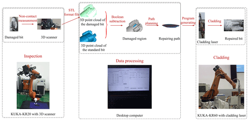
According to the overview above, an entire procedure is drawn for PDC bit repair in Fig. 2. In this paper, a dual-robot system is carried out to improve the efficiency of the laser cladding. First, the KUKA-KR20 industrial robot carrying a structural light 3D scanner is selected to perform an inspection for the sake of automation. The 3D point cloud obtained by a scanner is then processed by professional software – namely, Geometric Studio – and converted to a STL file. And finally, the damaged region of the bit can be obtained in such software via comparing the scanned model with the standard one. Second, another KUKA industrial robot (i.e., KUKA-KR60) holding a laser cladding device is used to complete the cladding process. Calibration, by which the position of the damaged region of the PDC bit expressed in the scanner coordinate system can be transformed into the equivalent in the KUKA-KR60 base robot coordinate system, is discussed emphatically in this paper as the existing works about laser cladding rarely pay attention to it. In our project, a mature product, i.e., a structural light 3D scanner designed by TECHLEGO, is used so that the internal parameters of the camera can be calibrated by the software provided by the manufacturer. There is a lot of literature about hand–eye calibration that proposed many methods for obtaining intrinsic and external parameters of cameras (Shiu and Ahmad, 1989), and the latest trend is to use fewer reference objects or reference points while driving the camera to make certain motions to realize calibration (Li et al., 2011; Ma, 1996; Tsai and Lenz, 1989; Zhuang et al., 1995). However the movement of the camera along with KUKA-KR20 is mainly used to obtain a relatively complete point cloud of the PDC bit from multiple perspectives rather than to realize calibration, and the calibration can be carried out by sufficient reference points – for instance, three points. Finally, an upper software that is deployed to a desktop computer is developed. By such software, the STL file of the damaged region of the PDC bit can be loaded after processing in Geometric Studio; the spatial coordinate of each point on the surface of the damaged region can be converted from the camera coordinate system into that of the KUKA-KR60 base robot coordinate system via the mapping of the transformation matrix; the path for the cladding head mounted on the KUKA-KR60 robot can be generated by the slicing method; and, finally, the path can be sent to the KUKA-KR60 robot to execute the cladding process.
The remaining chapters are arranged as follows: experimental platforms with key equipment and their functions are described in detail in Sect. 2, and the reconstruction of the damaged region of the PDC bit is then carried out in Sect. 3. In Sect. 4, a novel calibration between the scanner and the robot – namely, the three-point method – is proposed for laser cladding. Section 5 contains path planning and the method for the generation of the KUKA industrial robot program. Section 6 shows the repair experiment of the damaged PDC bit, and Sect. 7 is the conclusion.
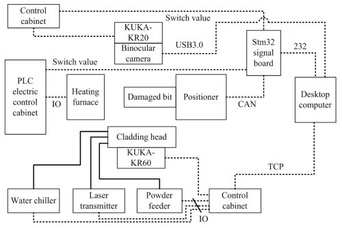
There is so much equipment on the experimental platform that their relationships cannot be described clearly all in one photo, so it is better to provide the plane layout of the whole platform, as shown in Fig. 3, and local photos of some important devices subsequently.
It can be seen in Fig. 3 that the platform can be divided into four parts by function: the KUKA-KR20 robot with binoculars (abbreviated as KR20), the KUKA-KR60 robot with a cladding head (abbreviated as KR60), a positioner and heating furnace (abbreviated as positioner), and an upper computer. The dotted lines between devices are used to indicate transmitting signals, and solid ones are used to indicate transmitting matter or energy.
In the KR20 subsystem, a blue light binocular camera designed by TECHLEGO is fixed on the end link of the robot (shown in Fig. 4a) by which the point cloud data of the damaged bit can be obtained. The camera has an accuracy of 0.05 mm, a scan time of less than 0.3 s, and a blue light as the light source to avoid interference of ambient light effectively. And start or stop is determined by a switch value being sent to the control cabinet of the robot (shown in Fig. 3).
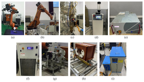
Figure 4Key equipment on the platform: (a) KUKA-KR20 industrial robot, (b) KUKA-KR60 industrial robot, (c) coaxial powder-feeding cladding header, (d) powder feeder, (e) semiconductor laser transmitter, (f) industrial water chiller, (g) positioned with bit, (h) heating furnace, and (i) medium-frequency heating power supply.
The KR60 subsystem consists of the KUKA-KR60 industrial robot (shown in Fig. 4b), coaxial powder-feeding cladding head (shown in Fig. 4c), powder feeder (shown in Fig. 4d), semiconductor laser transmitter (shown in Fig. 4e), and industrial water chiller (shown in Fig. 4f). The Ldm4000-100 laser that belongs to semiconductor laser is used as the core of the cladding system. It has a long service life, stable performance, energy utilization rate that can reach more than 40 %, and laser gate that can be opened and closed by the input–output (IO) port of the KUKA-KR60 robot (shown in Fig. 3). In order to avoid the high temperature under which the laser cladding cannot work normally, a special water chiller for the laser transmitter is equipped, with stable cooling water, of which the supplied temperature can be accurately adjusted, being provided. At the same time, it can also provide cooling water with suitable temperature for the cladding header. There is hope that the powder-feeding rate determined by the feeding equipment is uniform and can be precisely set up by the digital display control system, with a range of 0–25 g min−1. Furthermore, the control signal, including the cladding path, from the upper computer to the control cabinet of the KUKA-KR60 robot is transmitted through Ethernet based on the transmission control protocol (TCP) (shown in Fig. 3), while the other devices of the KR60 subsystem, such as a powder feeder, laser transmitter, and water chiller, are controlled by IO outputs of the control cabinet of the KUKA-KR60 robot through an ordinary conductor (shown in Fig. 3).
There are a positioner (shown in Fig. 4g) and a heating furnace (shown in Fig. 4h) mainly in the positioner subsystem. A CNC vertical rotary dividing head is used in the positioner subsystem, and the clamping device holding the damaged PDC bit is driven to rotating by a CNC servo motor, which can cooperate with the KR20 subsystem to achieve better camera scanning for the damaged region of the bit. Medium-frequency power is used to provide energy for the heating furnace, in which the bit is heated to exceed 700 °C and then taken out when laser cladding starts. If the temperature of the carcass of the bit is lower than 600 °C, the repairing process is terminated, and the bit is reheated by a furnace to exceed 700 °C again. The servo controller of the positioner can be driven based on the controller area network (CAN) bus standard, the heating furnace with a medium-frequency heating power supply is controlled by IO ports of the programmable logic controller (PLC) from the PLC electronic control cabinet, and the PLC is controlled by the switch values from the upper computer.
The upper computer subsystem, including a desktop computer and a signal board developed by a STM32 chip, is the control center of the whole system. The signal board obtains the command from the computer through a serial port based on the RS232 protocol and then sends instructions to the KR20 subsystem, PLC control cabinet, and positioner accordingly (shown in Fig. 3). The computer receives the point cloud data from the camera through the USB3.0 interface and sends data to and receives data from the KR60 subsystem through Ethernet based on TCP (shown in Fig. 3).
The whole cladding process can be described as follows:
- 1.
Scanning. The upper computer starts the whole process by sending commands via the STM32 signal board to the KUKA-KR20 robot, and the robot moves the camera to several positions in turn, which have been taught in advance, to scan the bit in multi-view.
- 2.
Reconstruction. A different point cloud set obtained by the camera from different perspectives is uploaded to the upper computer, and the image processing software provided by TECHLEGO can be used to organize the whole point cloud set into the final one, of the complete bit, by matching the same feature points of the bit in different sets. Comparing the final set of the bit with the standard one by Geometric Studio, the point cloud processing software, the damaged region of the bit that needs repair can be obtained.
- 3.
Path planning. Using the transformation matrix that obtained in advance by the three-point calibration method proposed in this paper, the 3D coordinates of any point in the damaged region of the bit that obtained in step (2) in the camera coordinate system can be transformed into that in the coordinate system of the KUKA-KR60 robot. A fold line with the width property can then be planned to cover the whole damaged region of the bit in the robot coordinate system.
- 4.
Cladding. Finally, the upper computer sends each endpoint of the fold line in turn as the repair path to the KUKA-KR60 robot via TCP, along with operating commands for the powder feeder, laser transmitter, and water chiller. The robot then drives the cladding head to complete repair according to the planned path.
The process of obtaining the point cloud model of a PDC bit by the binocular camera is a kind of 3D reconstruction, and the point cloud set of the complete bit has millions of data points. In order to avoid the abundant computation and the complexity of subsequent path planning for the bit with multiple damaged regions, using the point cloud data from a part of the bit within which there is only one breakage is recommended, as shown in Fig. 5a. At the same time, the standard point cloud set of such bit without any breakage at all is also provided, as shown in Fig. 5b.
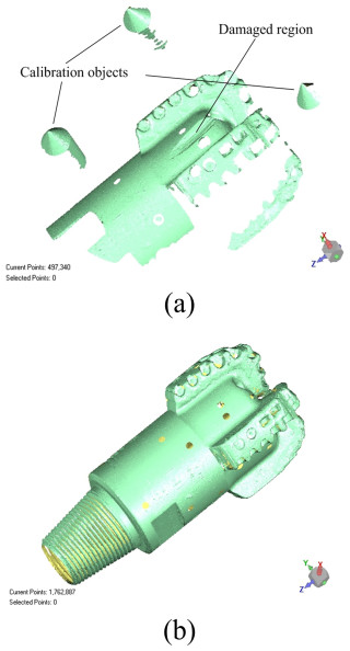
Figure 5Point cloud sets of the PDC bit: (a) point cloud of the damaged PDC bit and (b) point cloud of the standard bit without damage.
Three calibration objects appearing in Fig. 5a will be used for hand–eye calibration in the next section. For the reason that the geometric feature of the bit point cloud model is not intuitive enough, it is very hard to compare the two point cloud sets to obtain the damaged body of the bit. So, it is necessary to transform the point cloud set into the polygon model, which is mostly a triangle model. It can be seen that the model in Fig. 6a is the transition from the point cloud set in Fig. 5a and that the model in Fig. 6b is the transition from the point cloud set in Fig. 5b. Each model in Fig. 6 is the surface made up of a large number of triangles.
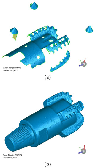
Figure 6Polygon models of the PDC bit: (a) polygon model of a damaged bit and (b) polygon model of a standard bit.
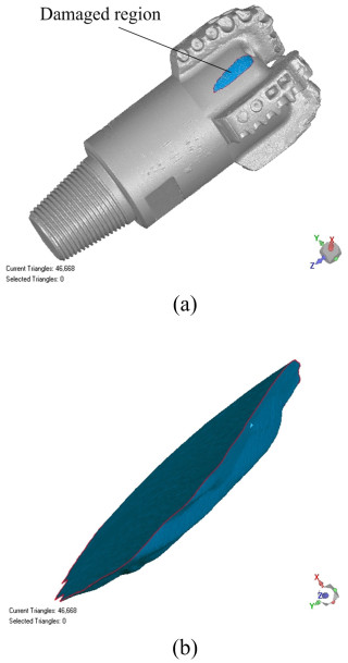
Comparing the polygon model of the damaged bit with that of the standard one, the damaged region of the bit can be obtained by Boolean subtraction as shown in Fig. 7a. In fact, the body finally obtained as shown in Fig. 7b is also enclosed by a large number of triangular surfaces, and the goal of laser cladding is to melt the powder in the damaged region of the bit to form such a body.
The geometric information of the body of the damaged region obtained in Fig. 7b cannot be used for laser cladding directly because the coordinate of each point on the obtained body is expressed in the camera coordinate system rather than in the robot coordinate system in which the laser head fixed on the robot can move as expected. So, it is necessary to find out more about the mapping relationship between the two coordinate systems and then to transform the coordinates of the points in the camera coordinate system to those in the robot coordinate system, which is known as hand–eye calibration. Conventional hand–eye calibration is to find the mapping between the 2D coordinates of the point on a plane and the 3D coordinates of the corresponding point in space. In such a project, a commercial binocular camera is used so that the mapping of coordinates to be determined is between the two points in space.
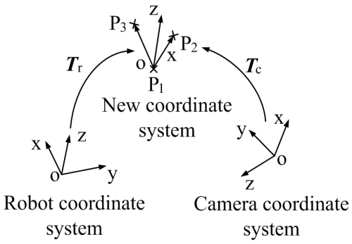
As shown in Fig. 8a, three cones are given out at first and then arranged not in a line in the coordinate system of the KUKA-KR60 robot. Finally, the tip of the cladding head is selected as the tool center point of the robot, and the tool center point is moved onto each tip of the cones to obtain the 3D coordinates by reading the teaching device of the KUKA-KR60 robot. The three points can also be captured by the camera, and the 3D coordinates of each tip of the cones can be obtained by point cloud processing software, as shown in Fig. 8b.
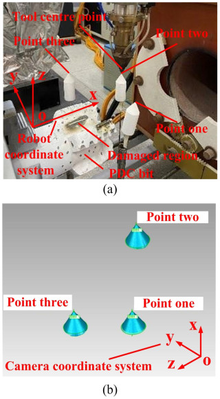
Figure 8Eye–hand calibration by three points in space: (a) three points in the coordinate system of the KUKA-KR60 robot and (b) three points in the coordinate system of the binocular camera.
In Fig. 9, the ith point (where i = 1, 2, 3) is marked as Pi, and a new coordinate system can be built using these three points as follows: label the vector from P1 to P2 as P1P2 and the vector from P1 to P3 as P1P3, and select P1 as the origin of such new coordinate system, the orientation of vector P1P2 as the orientation of the x axis of the new coordinate system, and the orientation of the cross product of vector P1P2 and vector P1P3 as the orientation of the z axis of the new coordinate system, with the y axis orientation of the system being determined by the right-hand screw rule. Tr is the transform matrix from the robot coordinate system to the new coordinate system, and Tc is the transform matrix from the camera coordinate system to the new coordinate system.
Assume the 3D coordinates of the ith (where i = 1, 2, 3) point with respect to the robot coordinate system are and that with respect to the camera coordinate system is . So, the unit vector relating to the robot coordinate system in the orientation of the x axis of the new coordinate system can be obtained as follows:
with representing the norm of vector P1P2 in the robot coordinate system.
And the unit vector relating to the robot coordinate system in the orientation of the z axis of the new coordinate system can be obtained as follows:
where × denotes the cross product of the two vectors.
The unit vector in the orientation of the y axis of the new coordinate system can also be obtained by the right-hand screw rule; that is, the following applies:
with × also denoting the cross product.
According to Eqs. (1), (2), and (3) and considering that P1 is the origin of the new coordinate system, the transform matrix from the robot coordinate system to the new coordinate system can be obtained as follows:
Also, the transform matrix from the camera coordinate system to the new coordinate system can be obtained as follows:
where , with ∥Pc2−Pc1∥ = representing the norm of vector P1P2 in the camera coordinate system,
, and .
Then, according to Eqs. (4) and (5), the transform matrix from the coordinate system of the KUKA-KR60 robot to the camera coordinate system can be obtained as follows:
So, the 3D coordinates of any point on the body of the damaged region of the PDC bit in the camera coordinate system, as shown in Figs. 6 to 9, can be transformed into the 3D coordinates in the robot coordinate system by transform matrix T; that is, the following applies:
where Pc is the coordinate of any point in the camera coordinate system and Pr is the respective coordinate in the robot coordinate system.
In the process of hand–eye calibration, all coordinates of the three points, both in the robot coordinate system and in the camera coordinate system, can be obtained, and by moving a cone, an additional set of coordinate data can also be obtained to verify the validity of the calibration method and the accuracy of the transform matrix, as shown in Table 1.
According to Eqs. (1) to (6) and the coordinate data from the first three points of Table 1, the transform matrix can be obtained as follows:
By substituting from the additional point of Table 1 and T from Eq. (8) into Eq. (7), the coordinate of the additional point can be obtained in the robot coordinate system as follows:
Then, according to Eq. (9) and Table 1, the distance between the transformed coordinate and the measured one is = 0.7423 mm. So, the precision of the proposed calibration method reaches our demands. If higher accuracy is needed, more cones and teaching operations can be added, while it is not necessary in our laser cladding project.
As shown in Figs. 5 to 7, what can be obtained by a scanner is the point cloud data of the PDC bit, and after Geometric Studio processing, the damaged body of the bit, which is surrounded by a large number of triangular surfaces, can also be obtained and finally be saved in a STL file. In the STL file, the coordinates of the three points of every triangle in the camera coordinate system and the normal vector of the triangular surface are stored. The matrix obtained by the proposed hand–eye calibration method can then be used to transform the coordinates of the three points of every triangle of the damaged body in the camera coordinate system into those in the base robot coordinate system, within which the planned path can be executed by the KUKA-KR60 robot.
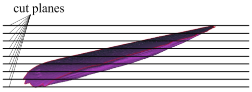
The cladding path, or the path of the tool center point of the KUKA-KR60 robot, can be planned within the damaged body of the bit in the robot coordinate system. As shown in Fig. 10, cutting the damaged body with a set of parallel planes, of which the height between any adjacent two is set to be equal to the height of the cladding alloy, and then, in each plane, a group of parallel line segments with the same width as the cladding alloy can be planned to fill in the whole plane within boundaries.
The reason why the fold line can be used in path planning is that the intersection lines of a certain cut plane and the damaged body surrounded by triangles form a polygon. An intuitive explanation can be that there are three cases when a line of the triangle of the damaged body intersects a certain cut plane. As shown in Fig. 11, type A stems from the intersection of an inner point of the line of the triangle and the certain cut plane, type B is the result of the intersection of an endpoint of the line and the certain cut plane, and type C means the line is just on the cut plane. So, the link line of any two adjacent points in type A, B, or C (taking the endpoints of type C) is also the intersection line of the triangular surface of the damaged body and the certain plane, and, finally, the link lines form a polygon.
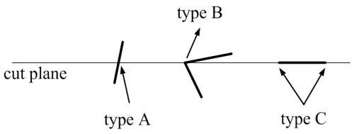
Figure 11Three cases of intersections of a line of the triangle of the damaged body and the certain cut plane.
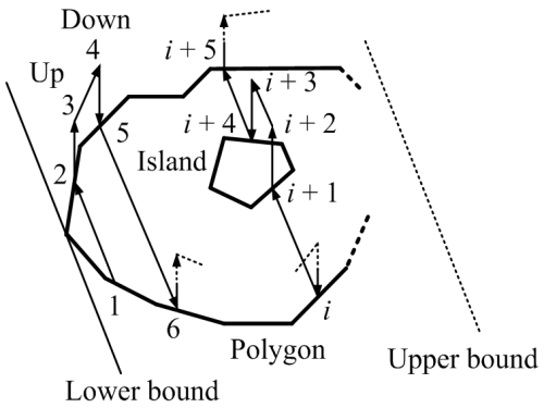
As seen in Fig. 12, parallel line segments, such as segments from intersection point 1 to 2, from 5 to 6, and so on, can be used to fill in the whole area of the polygon, and the cladding head must be lifted up at the end of each line segment move over to the top of the starting point of the next line segment and then fall down, mimicking the path from intersection point 2 to 3, from 3 to 4, and from 4 to 5. When the cladding head moves in the direction of the arrow along the line segments within the polygon, such as the segment from point 1 to 2, the powder flows out, and the alloy is in the process of cladding. While moving along the line segments out of the polygon, such as from 2 to 3, the powder is terminated. The distance between the two adjacent parallel line segments within the polygon is just the width of the cladding alloy, so the layer of the damaged region can be filled in by the cladding alloy. After a layer is filled in, the next layer can be repaired in the same way. If there is an island, which means there is no need for repair, the cladding head should step over it, meaning the path from intersection point i to i+1, then to i+2, then to i+3, then to i+4, and finally to i+5. In order to avoid accidents, the lifting height must be selected to ensure that the cladding head does not touch the bit.
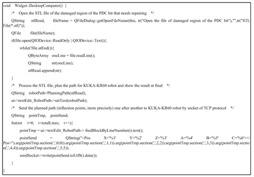
The main code and the functions with comments on the upper computer program are listed below. The program opens the STL file, then generates path or fold lines as described in Fig. 12 for the cladding head mounted on the KUKA-KR60 robot and finally sends the inflection points of the fold lines in sequence to the KUKA-KR60 robot via TCP via Ethernet, as shown in Fig. 13.
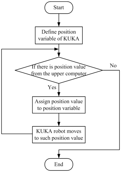
The main code of the KUKA-KR60 robot is also listed below in Fig. 13, where it can be seen that a loop statement ensures that the robot receives one inflection point of the planned path from the upper computer program and then drives the cladding head to such a point in a straight line via the ptp command (abbreviation for “point-to-point” command) and that the next inflection point is not accepted until the cladding head is completely driven to move to such point. The key to robot's successful reception of the planned path is that the program of the robot follows Ethernet format and TCP, as shown in Fig. 14.
Several groups of cladding experiments are carried out at different process parameters, and then the samples are sent to a professional institution for testing, with the optimal process parameters finally obtained.
The quality of cladding is mainly related to laser power, powder-feeding rate, and moving velocity of the laser cladding head. As shown in Fig. 15a, the laser power is so low that the powder cannot be melted adequately, and then the accumulative material appears, while in Fig. 15b, the laser power is so excessive that accidental over-burning of powder occurs in the cladding process. If the powder-feeding rate is too low, as shown in Fig. 15c, the cladding layer is too thin to meet the requirement; otherwise, in Fig. 15d, it will increase the subsequent amount of cutting work. When the laser head moves too fast, as shown in Fig. 15e, the powder can also not be melted adequately. Figure 15f shows the appearance of laser cladding under the optimal parameters.
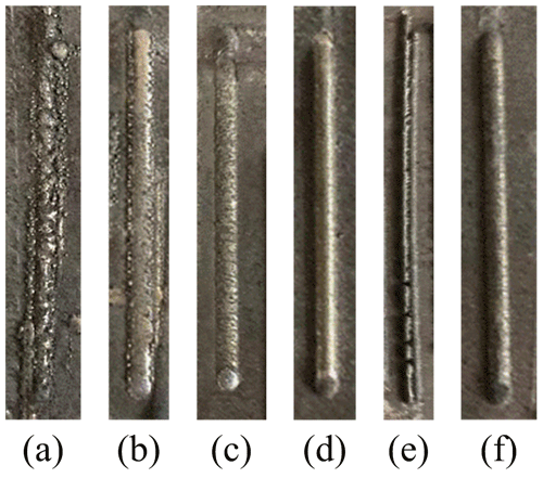
Figure 15Cladding samples for different process parameters: (a) lower laser power, (b) excessive laser power, (c) lower powder-feeding rate, (d) excessive powder-feeding rate, (e) fast movement of the laser, and (f) optimal parameters.
The recommended optimal process parameters are listed as follows in Table 2.
After setting the optimal process parameters for the whole set of equipment and sending the planned path to the KUKA-KR60 robot, the laser cladding device starts to work, as shown in Fig. 16a. Finally, the repaired bit can be seen in Fig. 16b.
According to the theoretical analysis and repair experiment for the damaged PDC bit above, the proposed dual-robot system, through which the two key tasks of repair – inspection and cladding – are, respectively, completed by two robots, is verified effectively and flexibly so that the process can be generalized for laser cladding repair of a blocky-surface region of damaged parts with high value. Furthermore, a novel calibration method, i.e., the three-point method, is proposed by which the position of the damaged region of the PDC bit expressed in the scanner coordinate system can be transformed into that expressed in the robot coordinate system. According to the existing literature, such calibration for laser cladding repair is not cared about, though it is the key link between inspection and cladding in that without it, one cannot locate the damaged region accurately, and then the cladding cannot be executed effectively. There are still two main aspects to be examined in future work: improving the accuracy of hand–eye calibration by supplementing the absolute positioning accuracy of the robot and integrating the processing functions of the 3D point cloud in the upper computer program that was developed so as to reduce the number of commercial software used.
Software code in this study can be requested from the corresponding author.
Research data in this study can be requested from the corresponding author.
JiW carried out the experiments and wrote the original draft, ZM contributed to the conception of the study and designed the experiments, JuW developed the upper computer program and robot program, and WP helped revise the paper and gave some advice on robot design. All authors have read and agreed to the published version of the paper.
The contact author has declared that none of the authors has any competing interests.
Publisher’s note: Copernicus Publications remains neutral with regard to jurisdictional claims made in the text, published maps, institutional affiliations, or any other geographical representation in this paper. While Copernicus Publications makes every effort to include appropriate place names, the final responsibility lies with the authors.
The authors acknowledge the financial support of the Guangxi Key Laboratory of Wireless Wideband Communication and Signal Processing of China.
This research has been supported by the Guangxi Key Laboratory of Wireless Wideband Communication and Signal Processing, Guilin University of Electronic Technology (grant no. GXKL06200123).
This paper was edited by Daniel Condurache and reviewed by four anonymous referees.
Chen, G., Han, Y., Li, Y., Shen, J., Tu, J., Yu, Z., Zhang, J., Cheng, H., Zhu, L., and Dong, F.: Autonomous gait switching method and experiments of a hexapod walking robot for Mars environment with multiple terrains, Intel. Serv. Robot., 17, 533–553, https://doi.org/10.1007/s11370-023-00508-z, 2024.
Davis, T. and Shin, Y.: Vision-based clad height measurement, Mach. Vision Appl., 22, 129–136, https://doi.org/10.1007/s00138-009-0240-9, 2011.
Diao, X., Chi, W., and Wang, J.: Graph neural network based method for robot path planning, Biomimetic Intelligence and Robotics, 4, 100147, https://doi.org/10.1016/j.birob.2024.100147, 2024.
Gao, J., Folkes, J., Yilmaz, O., and Gindy, N.: Investigation of a 3D non-contact measurement based blade repair integration system, Aircr. Eng. Aerosp. Tec., 77, 34–41, https://doi.org/10.1108/00022660510576028, 2005.
Gao, J., Chen, X., Yilmaz, O., and Gindy, N.: An integrated adaptive repair solution for complex aerospace components through geometry reconstruction, Int. J. Adv. Manuf. Tech., 36, 1170–1179, https://doi.org/10.1007/s00170-006-0923-6, 2008.
Görgl, R. and Brandstätter, E.: Laser materials processing of complex components from reverse engineering via automated beam path generation to short process development cycles, P. SPIE, 10254, 114–121, https://doi.org/10.1117/12.2256825, 2016.
Guo, Y., Huang, L., Liu, Y., Liu, J., and Wang, G.: Establishment of the complete closed mesh model of rail-surface scratch data for online repair, Sensors, 20, 4736, https://doi.org/10.3390/s20174736, 2020.
Huang, W., Jiang, Z., Wang, T., Wang, Y., and Hu, X.: Remanufacturing scheme design for used parts based on incomplete information reconstruction, Chin. J. Mech. Eng., 33, 72–85, https://doi.org/10.1186/s10033-020-00457-z, 2020.
Li, J., Chen, M., Jin, X., and Yao, F.: Calibration of a multiple axes 3-D laser scanning system consisting of robot, portable laser scanner and turntable, Optik, 122, 324–329, https://doi.org/10.1016/j.ijleo.2010.02.014, 2011.
Li, J., Zhang, D., and Su, Z.: The research of mould's digital repairing based on laser cladding, Adv. Mat. Res., 860–863, 2678–2681, https://doi.org/10.4028/www.scientific.net/AMR.860-863.2678, 2014.
Li, Q., Liu, E., Cui, C., and Wu, G.: An open-closed-loop iterative learning control for trajectory tracking of a high-speed 4-dof parallel robot, Intell. Robot, 2. 89–104, https://doi.org/10.20517/ir.2022.02, 2022.
Li, Y., Chen, T., and Liu, D.: Path planning for laser cladding robot on artificial joint surface based on topology reconstruction, Algorithms, 13, 93, https://doi.org/10.3390/a13040093, 2020.
Liu, H., Hu, Z., Qin, X., Wang, Y., Zhang, J., and Huang, S.: Parameter optimization and experimental study of the sprocket repairing using laser cladding, Int. J. Adv. Manuf. Tech., 91, 3967–3975, https://doi.org/10.1007/s00170-017-0066-y, 2017.
Liu, J.: Online measurement based tool path generation toward integrated robotic laser cladding, Ind. Robot, 40, 494–501, https://doi.org/10.1108/IR-09-2012-408, 2013.
Liu, J., Sun, W., and Huang, Y.: An algorithm for trajectory planning of complex surface parts for laser cladding remanufacturing, P. I. Mech. Eng. B-J. Eng., 235, 2025–2032, https://doi.org/10.1177/0954405420987712, 2021.
Luo, Z., Zhang, K., Wang, Z., Zheng, J., and Chen, Y.: 3D pose estimation of large and complicated workpieces based on binocular stereo vision, Appl. Optics, 56, 6822–6836, https://doi.org/10.1364/AO.56.006822, 2017.
Ma, S.: A self-calibration technique for active vision systems, IEEE T. Robotic. Autom., 12, 114–120, https://doi.org/10.1109/70.481755, 1996
Montoya-Zapata, D., Creus, C., Oritiz, I., Alvarez, P., Moreno, A., Posada, J., and Ruiz-Salguero, O.: Generation of 2.5D deposition strategies for LMD-based additive manufacturing, Procedia Comput. Sci., 180, 280–289, https://doi.org/10.1016/j.procs.2021.01.165, 2021.
Rong, Y., Xu, J., and Sun, Y.: A surface reconstruction strategy based on deformable template for repairing damaged turbine blades, P. I. Mech. Eng. G-J. Aer., 228, 2358–2370, https://doi.org/10.1177/0954410013517091, 2014.
Shiu, Y. C. and Ahmad, S.: Calibration of wrist-mounted robotic sensors by solving homogeneous transform equations of the form AX=XB, IEEE T. Robotic. Autom., 5, 16–29, https://doi.org/10.1109/70.88014, 1989.
Tsai, R. and Lenz, R.: A new technique for fully autonomous and efficient 3D robotics hand/eye calibration, IEEE T. Robotic. Autom., 5, 345–358, https://doi.org/10.1109/70.34770, 1989.
Um, J., Rauch, M., Hascoet, J., and Stroud, I.: STEP-NC compliant process planning of additive manufacturing: remanufacturing, Int. J. Adv. Manuf. Technol., 88: 1215-1230, https://doi.org/10.1007/s00170-016-8791-1, 2017.
Vilar, R.: Laser cladding, J. Laser Appl., 11, 64–79, https://doi.org/10.2351/1.521888, 1999.
Wang, X., Sun, W., Chen, Y., Zhang, J., Huang, Y., and Huang, H.: Research on trajectory planning of complex curved surface parts by laser cladding remanufacturing, Int. J. Adv. Manuf. Tech., 96, 2397–2406, https://doi.org/10.1007/s00170-018-1737-z, 2018.
Xu, L., Cao, H., Liu, H., and Zhang, Y.: Study on laser cladding remanufacturing process with FeCrNiCu alloy powder for thin-wall impeller blade, Int. J. Adv. Manuf. Tech., 90, 1383–1392, https://doi.org/10.1007/s00170-016-9445-z, 2017.
Zhang, K., Li, D., Gui, H., and Li, Z.: An adaptive slicing algorithm for laser cladding remanufacturing of complex components, Int. J. Adv. Manuf. Tech., 101, 2873–2887, https://doi.org/10.1007/s00170-018-3107-2, 2019.
Zheng, H., Cong, M., Dong, H., Liu, Y., and Liu, D.: CAD-based automatic path generation and optimization for laser cladding robot in additive manufacturing, Int. J. Adv. Manuf. Tech., 92, 3605–3614, https://doi.org/10.1007/s00170-017-0384-0, 2017.
Zheng, H., Cong, M., Liu, D., Dong, H., and Liu, Y.: Robot path optimization for laser cladding forming, Ind. Robot, 46, 281–289, https://doi.org/10.1108/IR-07-2018-0148, 2019a.
Zheng, H., Cong, M., Liu, D., Dong, H., and Liu, Y.: Optimization of STL model and layer shape for laser cladding forming, Int. J. Adv. Manuf. Tech., 100, 599–608, https://doi.org/10.1007/s00170-018-2714-2, 2019b.
Zhu, G., Shi, S., Fu, G., Shi, J., Yang, S., Meng, W., and Jiang, F.: The influence of the substrate-inclined angle on the section size of laser cladding layers based on robot with the inside-beam powder feeding, Int. J. Adv. Manuf. Technol., 88: 2163-2168, https://doi.org/10.1007/s00170-016-8950-4, 2017.
Zhu, L., Wang, S., Pan, H., Yuan, G., and Chen, X.: Research on remanufacturing strategy for 45 steel gear using H13 steel powder based on laser cladding technology, J. Manuf. Process., 46, 344–354, https://doi.org/10.1016/j.jmapro.2019.12.009, 2020.
Zhuang, H., Wang, K., and Roth, Z.: Simultaneous calibration of a robot and a hand-mounted camera, IEEE T. Robotic. Autom., 11, 649–660, https://doi.org/10.1109/70.466601, 1995.
- Abstract
- Introduction
- Experimental platform of the dual-robot system
- Three-dimensional reconstruction and damage identification of the PDC bit
- Hand–eye calibration using three points in space
- Repair-path planning and robot program generation
- The repair test of the damaged bit
- Conclusions
- Code availability
- Data availability
- Author contributions
- Competing interests
- Disclaimer
- Acknowledgements
- Financial support
- Review statement
- References


