the Creative Commons Attribution 4.0 License.
the Creative Commons Attribution 4.0 License.
 | 14 Feb 2025
Design of a magnetorheological (MR) suspension damper for an agricultural tractor seat based on an adaptive neuro-fuzzy inference system (ANFIS) and active disturbance rejection control (ADRC)
Luyang Zhou
Zhixiong Zheng
Jianjin Wu
Minghao Duan
To enhance the vibration isolation functionality of the seat suspension system, particularly in the context of magnetorheological (MR) seat dampers, a pioneering semi-active controller integrating an adaptive neuro-fuzzy inference system (ANFIS) and active disturbance rejection control (ADRC) was devised. Firstly, the Bouc–Wen model was employed to establish the dynamic model of the damper based on experimental data, thereby ensuring an accurate description of the actual physical behaviours. Subsequently, the ANFIS technology was employed to develop an inverse model, which detailed the structural design and training process of the inverse model. This resulted in the achievement of precise prediction and control of the damper behaviour. Ultimately, the ANFIS inverse model was integrated with the designed ADRC controller to create an innovative control scheme for the seat suspension system of a two-degrees-of-freedom dynamic model, and a simulation analysis was conducted. The simulation results demonstrate that the root-mean-square (rms) value of the vertical vibration acceleration of the ADRC-controlled suspension system decreased by 68.9 % and 34.4 % in comparison to proportional–integral–derivative (PID) control and passive control, respectively. The rms value of the dynamic disturbance of the ADRC-controlled suspension system decreased by 50.0 % and 28.6 % compared to PID control and passive control, respectively. This verifies the performance of the proposed controller, particularly in the precise control of damping force, demonstrating outstanding effectiveness.
- Article
(7196 KB) - Full-text XML
- BibTeX
- EndNote


In recent years, there has been a notable shift in the engineering community's attention towards semi-active vibration control systems (Ahn et al., 2023; Bhowmik and Debnath, 2024; Luan et al., 2023). These systems are capable of providing vibration reduction effects that are comparable to those of active control devices while simultaneously maintaining low energy consumption and the reliability of passive devices. Among the numerous semi-active control systems, magnetorheological (MR) dampers have garnered considerable attention due to their simplicity, reliability, and robustness. Notably, semi-active control suspension systems utilizing MR dampers have been extensively investigated in the context of vehicle vibration comfort (Wang et al., 2024; Kumar and Bhushan, 2024; Xie and Hua, 2024).
The majority of research conducted on MR semi-active suspension systems is concentrated in three primary areas: the dynamic modelling of MR dampers, the modelling of suspension systems and their vibration transmission characteristics, and the simulation analysis and experimental validation of semi-active suspension control systems. Miao et al. (2024) employed the normalized Bouc–Wen model to ascertain the nonlinear characteristics of the MR rotary dampers. By means of numerical simulations, the effects of MR semi-active suspension and passive suspension on the dynamic performance of tracked vehicles under a variety of operating conditions were investigated. In comparison to passive suspension, the MR semi-active suspension exhibited enhanced vibration reduction capabilities across diverse road grades and vehicle speeds, thereby substantiating the superiority of this suspension system (Miao et al., 2024). The study by de Brett et al. (2023) proposed and validated a methodology for the analysis and modelling of the nonlinear vibration transfer of vehicle suspension dampers at low audio frequencies. Utilizing experimental data and model validation, they conducted nonlinear dynamic modelling and analysis of the front and rear suspension dampers of the test vehicle. The authors selected and fitted appropriate models based on experimental data and conducted a comprehensive analysis of various nonlinear effects, including the influence of friction and the mechanical characteristics of piston valves on the dynamic performance of the dampers (de Brett et al., 2023). Turgay Ergin and Meral Özarslan Yatak proposed and validated a proportional–integral–derivative (PID) controller based on particle swarm optimization (PSO) for a semi-active suspension system (SASS) of a quadricycle. They utilized artificial neural networks (ANNs) to simulate the model of the MR damper and conducted a series of experiments to assess the efficacy of the proposed algorithm, thereby confirming the superior performance of the controller in practical applications (Ergin and Yatak, 2023). The mechanical characteristics of MR dampers and the establishment of their forward and inverse models have constituted a research focus as the actuating elements in semi-active suspension systems. This is evidenced by the extensive literature on the subject (Gong et al., 2023; Tantray, 2023; Bahar et al., 2024). The forward model predicts the output damping force based on the input current and the relative motion state of the piston. The primary applications of this method are to elucidate the operational mechanism of MR dampers, to substitute for actual dampers in simulations, and to function as force sensors in actual control. The inverse model is employed to forecast the optimal control current in accordance with the desired control force and the piston's motion state, a process of considerable practical consequence in control applications (Abd Elwahed et al., 2024).
The forward dynamic models of MR dampers currently include the Bingham model (Zhao et al., 2024), the nonlinear hysteretic viscous model (Zhao et al., 2018), the phenomenological model (Jiang et al., 2023), the Dahl model (Aguirre et al., 2012), the LuGre model (Jiménez and Álvarez-Icaza, 2005), the sigmoid generalized hysteresis model, the hyperbolic tangent model, the polynomial model, the neural network model, and the neural-network–fuzzy model (Archakam and Muthuswamy, 2021; Lu et al., 2023; Wei et al., 2021). However, these models seldom take into account the impact of excitation characteristics on damper properties. Given the inherent variability of excitation characteristics in practical applications, models identified under specific excitation conditions may not fully align with the needs of real-world applications. In light of these considerations, this paper puts forth a dynamic model for MR dampers that is accurate, simple, highly adaptive, and reversible. Based on experimental data, a Bouc–Wen model was constructed to represent the forward mechanical performance of MR dampers, and an adaptive neuro-fuzzy inference system (ANFIS) was employed to develop an inverse dynamic model of MR dampers. The inverse model was subsequently integrated with the active disturbance rejection control (ADRC) for joint simulation and optimal control, and the resulting simulation results were subjected to analysis.
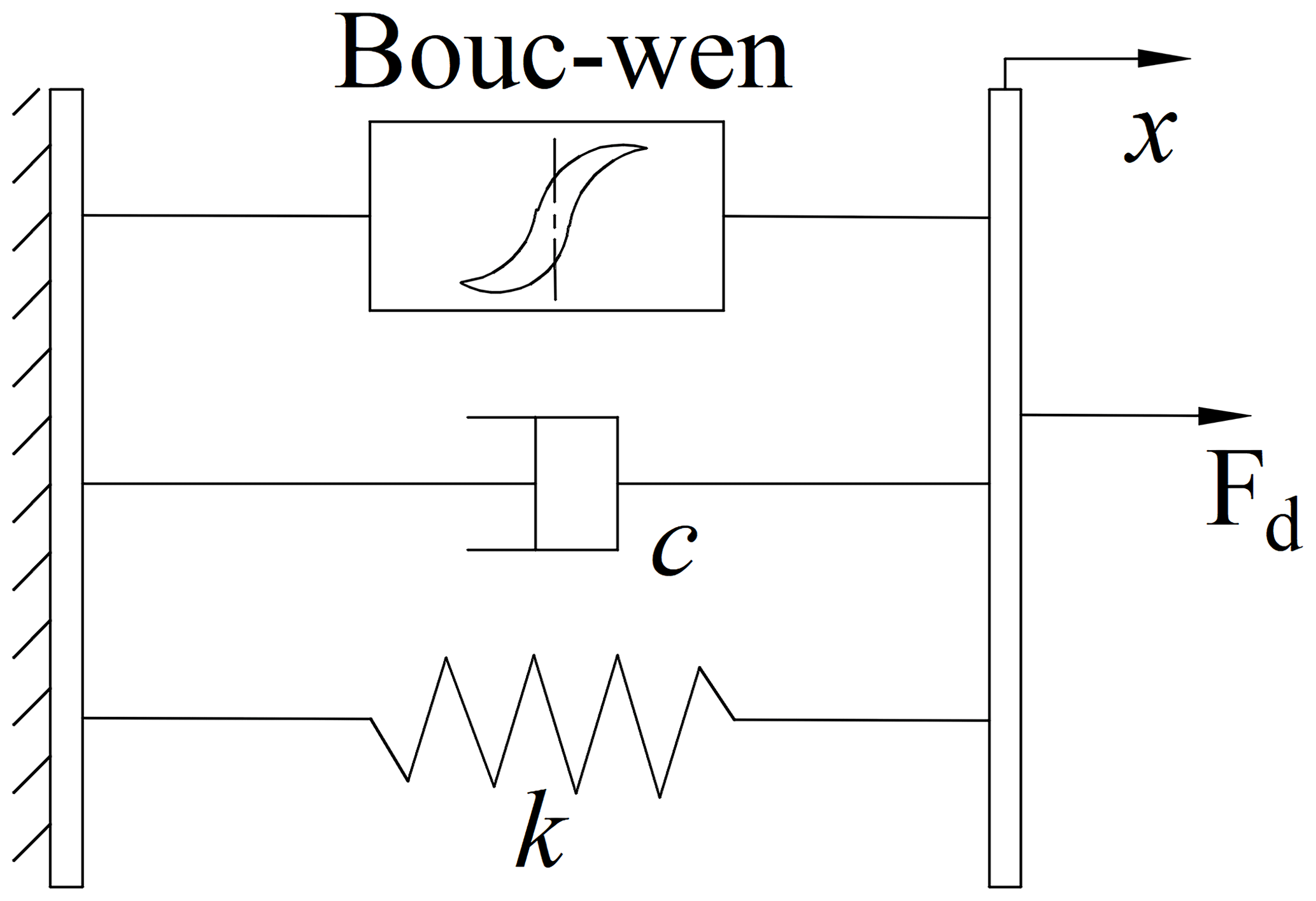
In system dynamics simulation, it is essential to establish a parametric dynamic model of the magnetorheological damper to ensure that the simulation results align with the actual situation. The Bouc–Wen model is particularly effective in addressing the nonlinear hysteresis characteristics of the magnetorheological damper, and as a result, it has become a prevalent choice for simulating and analysing actual problems. The Bouc–Wen model comprises a hysteresis system, a spring, and a viscous damping element in parallel, as shown in Fig. 1.
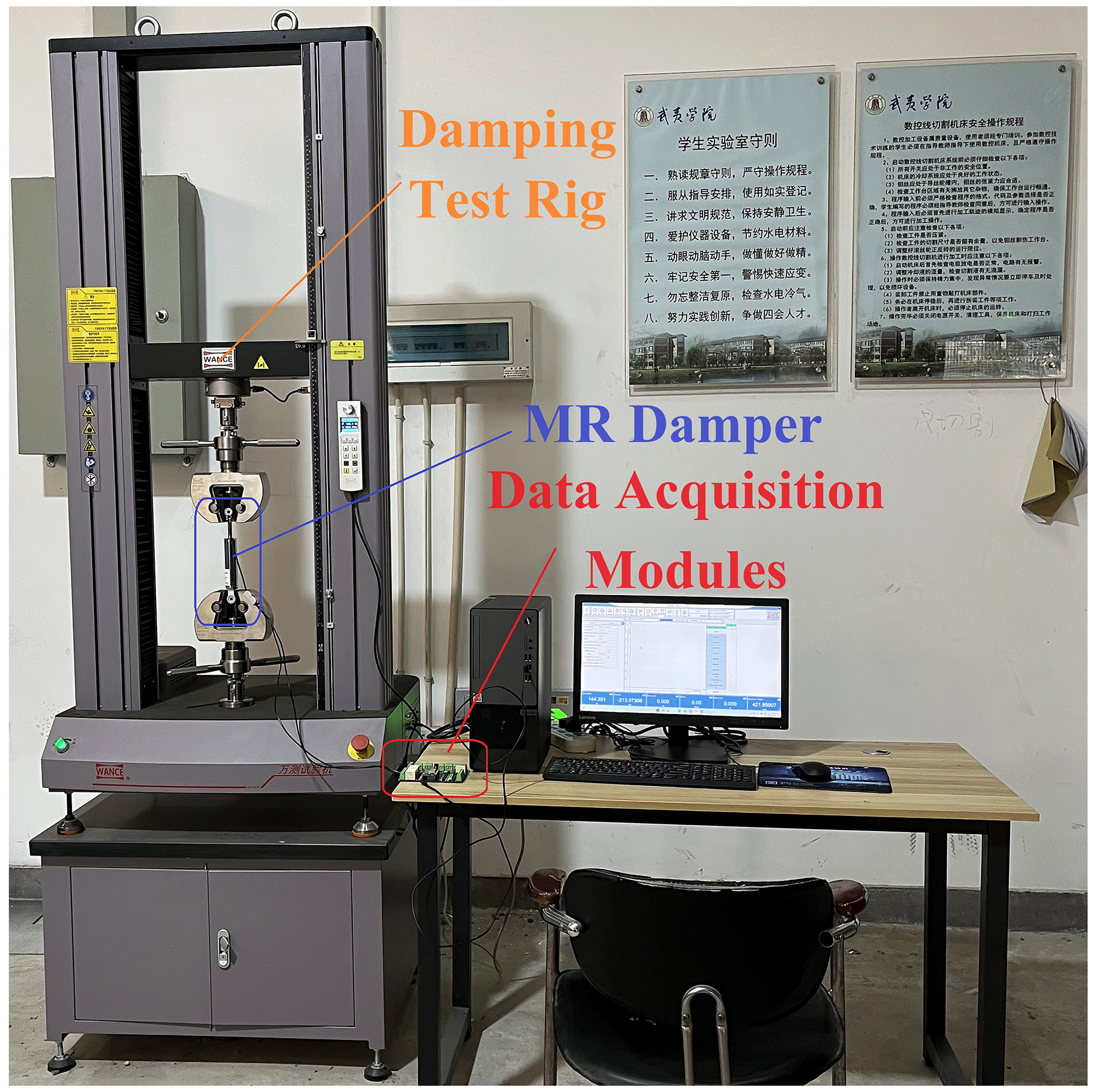
To ensure the accurate and effective control of the output damping force of the magnetorheological damper, it is essential to guarantee the precision and reliability of the model. To assess the damping-force–velocity and damping-force–displacement characteristics of the magnetorheological damper, we utilize an electro-hydraulic servo fatigue machine, as illustrated in Fig. 2.
The Bouc–Wen model demonstrates superior efficacy in representing the relationship between the output damping force of the MR damper and the relative displacement and velocity of the piston. Its expression for the damping force is
where F represents the damping of the MR damper, c0 denotes the viscous damping coefficient, k0 signifies the stiffness coefficient, α stands for the proportional adjustment parameter of the hysteresis force in the damping force, and x0 is the relative equilibrium position offset displacement. Additionally, z represents the hysteresis variable. The variables x and represent the relative displacement and relative velocity of the MR damper piston, respectively. The parameter n is referred to as the rounding coefficient, while γ is the width adjustment coefficient of the hysteresis model. The height adjustment coefficient of the hysteresis model is represented by β, and the scaling factor is designated as A. The adjustment coefficient of the hysteresis model, β, represents the height adjustment coefficient of the hysteresis model, whereas A denotes the scale factor.
The Bouc–Wen model comprises eight unknown parameters, and the code for identification methods such as the genetic algorithm and particle swarm algorithm is both cumbersome and complex. This paper therefore employs the nonlinear least squares method in the “Design Optimization” toolbox in Simulink to carry out the parameter identification. The iterative algorithms are automatically called using the experimental data to achieve a high degree of correlation between the experimental and simulation values, thus identifying all the parameters. The nonlinear least squares method identifies the optimal solution to the estimated objective function Q by locating the minimum value of the objective function Q of the error sum of squares. The identified model is expressed mathematically as follows:
where y is the output of the system; is the input series of the system; and is the parameter series. Once the parameters have been estimated, the mathematical expression of the model, f, is known, and the data are obtained experimentally as (, ⋯, y1) (, ⋯, y2) ⋯ (, ⋯, yn). The objective function Q, which represents the sum of squared errors for the nonlinear model, is defined as follows:
The eight unknown parameters in the Bouc–Wen model were identified through the use of measured piston relative displacements, velocities, and currents as inputs and the damping force as the output. The identification flowchart is shown in Fig. 3.
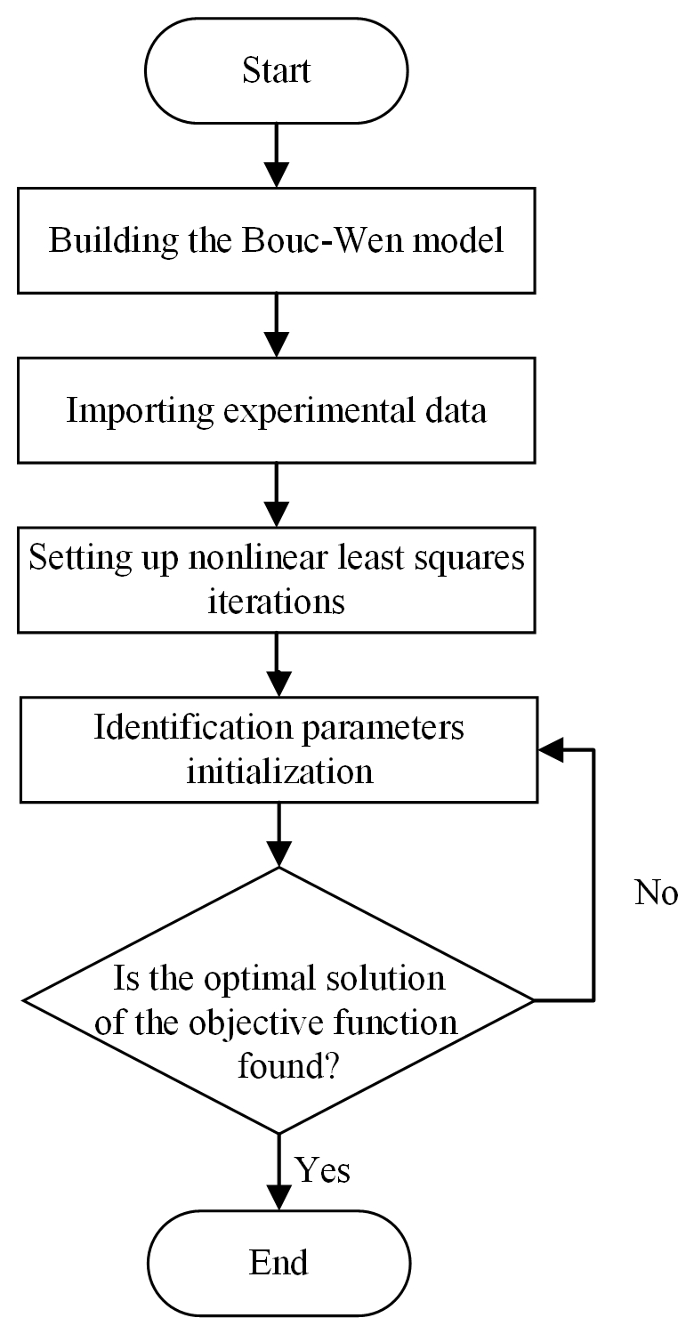
Firstly, the constructed Bouc–Wen model was employed to import the experimental data, which were obtained through the “Parameter Estimation” toolbox. The input data consisted of displacement, velocity, and current values, while the output data represented the damping force. The initial values of the identification parameters were established, and the identification range was defined based on experimental data and prior experience, as illustrated in Table 1.
Table 1Bouc–Wen parameter identification and initial values and ranges.

Subsequently, the optimization option was selected via the toolbox, and the nonlinear least squares method was selected for iterative computation. The cost function was then chosen, and the squared difference was employed for parameter estimation. The parameter estimation was terminated according to the proximity of the simulation curves to the experimental data, specifically when Q≤0.001.
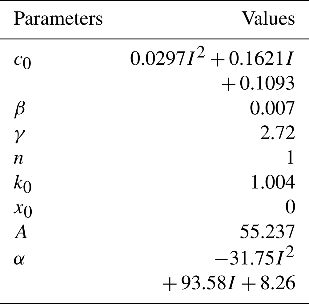
Following the completion of the Simulink modelling of the Bouc–Wen model, the experimental data obtained from an input excitation frequency of 2 Hz; an amplitude of 10 mm; and input currents of 0, 0.5, 1.0, and 1.5 A were selected for the identification of the kinetic model parameters. The Bouc–Wen model comprises a total of eight unknown parameters, each of which exerts a distinct influence on the model's behaviour. The preliminary identification of model parameters revealed that the values of the two parameters α and c0 undergo significant changes in response to variations in current. Consequently, α and c0 were set to vary in accordance with changes in working conditions, while the remaining parameters were maintained at a constant value. The fitting of the Bouc–Wen model indicated that the relationship between α and c0 and the current can be expressed by a quadratic polynomial. The synthesis of the other six fixed parameters yielded the Bouc–Wen parameter fitting results, which are presented in Table 2.
Once the parameters had been identified, the resulting data were plotted and compared with the test results obtained at an excitation frequency of 2 Hz and an amplitude of 10 mm, as illustrated in Fig. 4.
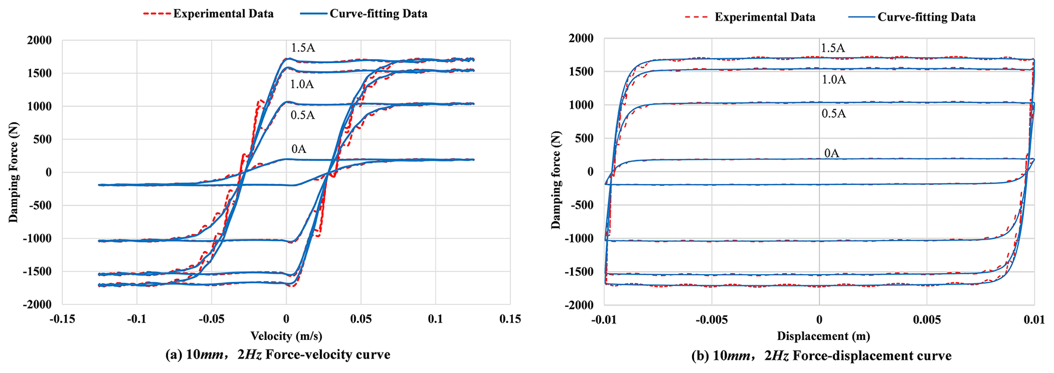
Figure 4 illustrates the experimental test results, represented by the solid line, and the model parameter fitting results, depicted by the dashed line. As can be seen from the figure, the curve obtained from parameter fitting using the Bouc–Wen model (applied using Simulink parameter identification) is in general agreement with the curve obtained from the characteristic test of the damper, and the fitting effect is satisfactory.
The damping force generated by the MR damper is mainly determined by the input current, the relative piston acceleration, and the relative piston displacement. Only when the input current can be directly controlled can the MR damper function properly. Therefore, it is important to obtain the command current according to the desired force in practical applications. Since the ANFIS has a general approximation ability for nonlinear systems (Karaboga and Kaya, 2019), in this section the ANFIS technique is applied to the inverse model building of the MR damper to build the inverse model of the control current and to calculate the current required to obtain the desired damping force.
3.1 Adaptive neuro-fuzzy inference system
The ANFIS is a combination of an adaptive network and a fuzzy inference system, which inherits the interpretability of a fuzzy inference system and the learning ability of an adaptive network; it utilizes the learning mechanism of a neural network to automatically extract the rules from the input and output sample data, constituting the adaptive neuro-fuzzy controller, and can autonomously adjust the parameters of the system through hybrid algorithms so as to make the output of the system closer to the actual output (Bilgundi et al., 2022). The ANFIS consists of five functional modules: input layer, affiliation layer, rule layer, decision layer, and output layer, as shown in Fig. 5.
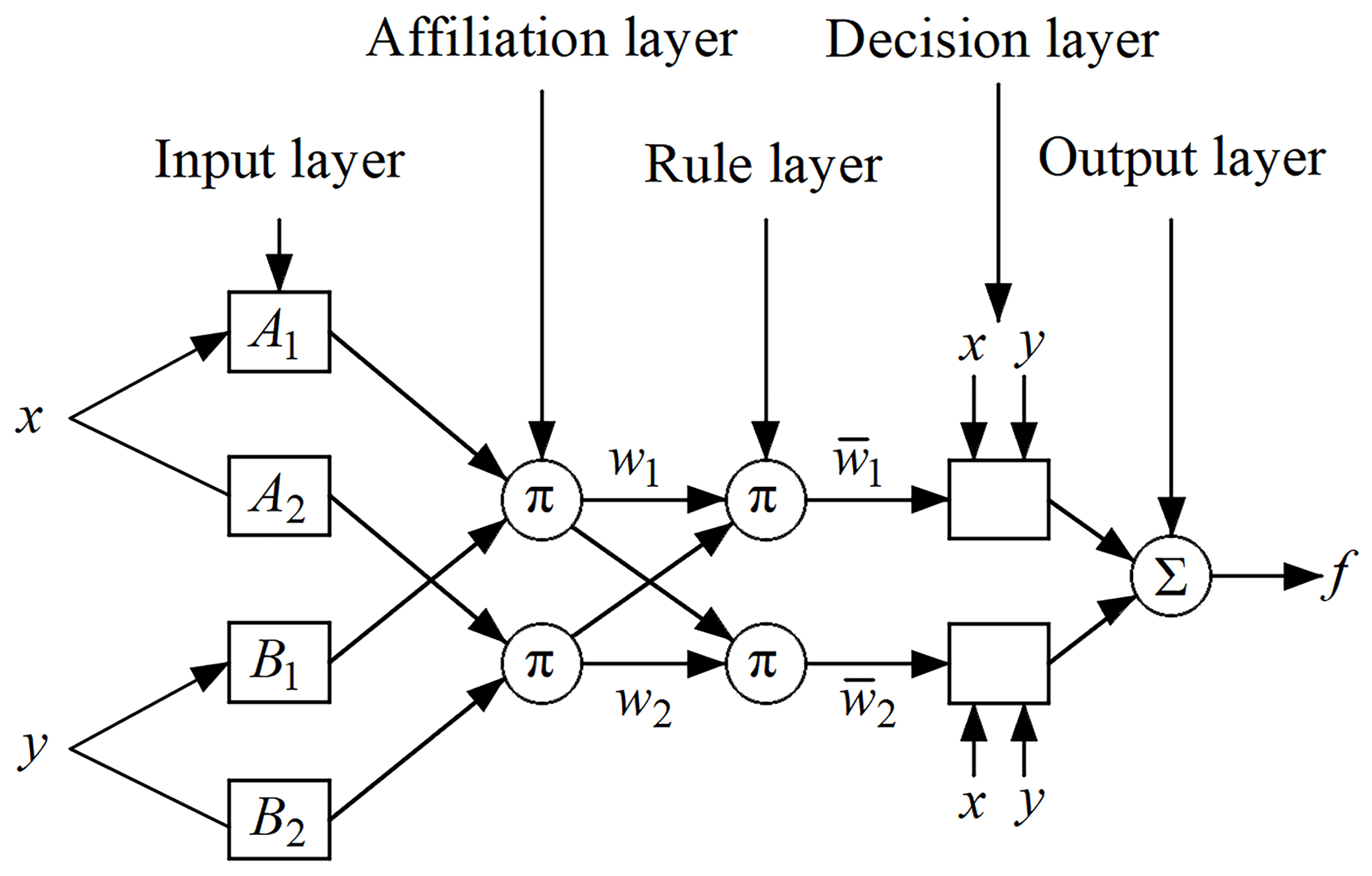
In Fig. 5, x and y are input variables that form two if–then rules. Rule 1: if x is A1 and y is B1, then continue; rule 2: if x is A2 and y is B2, then continue (where p2, qi, and ri are variable coefficients).
The following is a description of the ANFIS layers+:
-
Input layer. For adaptive nodes, fuzzy input features with an affiliation function to get the degree of affiliation in the interval and the output are denoted as
where x is the input of node i, and μAi(x) is the affiliation function, which usually has a bell curve, cosine function, or Gaussian function. In this paper, a Gaussian function is used, i.e.
where ci and σi are parameters set by the Gaussian function.
-
Affiliation layer. This is a fixed node, denoted by ∏. The trigger strength ωi of each rule is obtained by multiplying the affiliation degree of each feature, and the output is
-
Rule layer. The classification process is performed to normalize the trigger strength of each rule obtained from the previous layer (i.e. it is the corresponding probability of use of the rule), which is used to indicate the triggering ratio of the rule (Bilgundi et al., 2022).
where is the normalized trigger strength.
-
Decision layer. For adaptive nodes, the output of each node is simply the product of the normalized trigger strength and a first-order polynomial, and the output is the following equation:
-
Output layer. It is a fixed node where the exact output is obtained by deburring, characterized by Σ. A weighted average of the results of each rule gives the final output of the model, as in the following equation:
ANFIS overcomes the black-box characteristics of simple neural networks, as well as the incompleteness and roughness of the inference rules in the fuzzy inference process, and maximally simplifies the data processing with adaptive, self-organizing, and self-learning characteristics.
In this paper, a hybrid optimization method combining backpropagation and least squares is employed for training the model network. It is assumed that the parameters of the ANFIS system can be decomposed into two sets of outputs and inputs. In the event that the outputs are provided, the system will output a linear function. Consequently, the linear parameters can be identified through the least squares method. Once the inputs have been identified, the parameters in the output can be updated using the gradient method. The matrix form of the least squares method is presented in Eq. (10).
where n is the total number of training data input–output pairs; is the predicted output of the network, where the backward parameters are derived from Eq. (11); and is the measured output.
The discrepancy between the desired and predicted outputs is conveyed from the output layer to the input layer, where it is utilized to update the weights through the backpropagation algorithm, as illustrated in Eq. (12).
According to Eq. (12), the weights of the input layer can be updated as shown in Eq. (13):
where k is the input–output training pair, and M denotes each layer backward from the initial stage of output backpropagation.
3.2 Training and validation of the ANFIS inverse model for MR dampers
In order to construct an accurate ANFIS inverse model, it is necessary to collect input–output data pairs that contain a sufficient amount of information. This information is then used to train the ANFIS model, after which the trained model is validated.
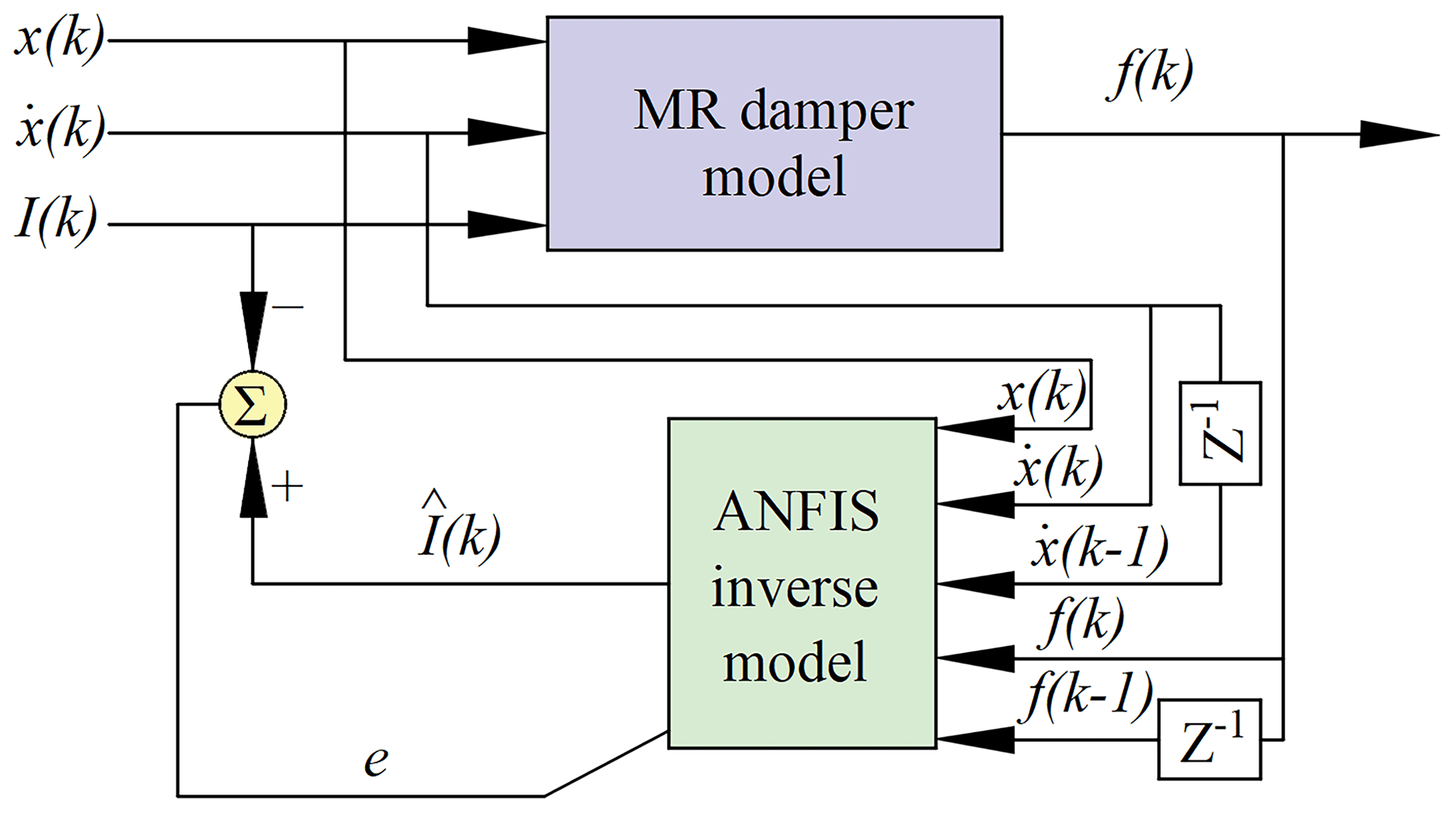
In the construction of an input–output dataset, the ANFIS develops a fuzzy inference system (FIS) whose membership function parameters are calibrated through the implementation of a hybrid algorithm. In general, the greater the number of inputs, the greater the accuracy of the inverse model. However, as the number of inputs increases, the inverse model will become increasingly complex, resulting in a significant increase in training time (Ghenai et al., 2022). In order to achieve an equilibrium between the accuracy and time consumption of the model, the inputs to the inverse model are selected to be the current displacement x(k), the current velocity , the previous velocity , the current desired damping force f(k), and the previous desired damping force f(k−1), while the output is the command current I(k). Figure 6 illustrates the application of the ANFIS approach to simulate the inverse dynamics of the MR damper. The displacement input is a Gaussian white noise signal with a frequency between 0 and 13 Hz and an amplitude of ±20 mm. The command current input was generated from a Gaussian white noise signal with a range of 0 to 1.5 A and a frequency of 0 to 2 Hz. The desired damping force was generated by the Bouc–Wen model, which was constructed in the previous section based on the displacement and command current inputs. The data were collected for a period of 10 s and subsequently sampled at a rate of 2000 Hz, resulting in the generation of 20 000 data points. The initial 10 000 data points were designated as training data, while the subsequent 10 000 data points were utilized as a verification set.

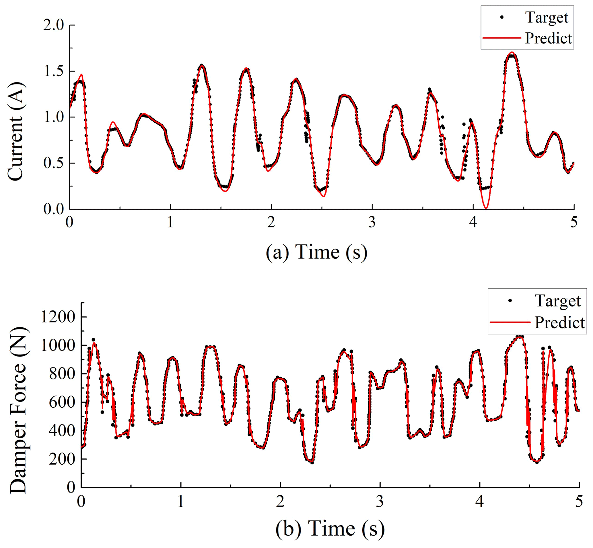
Figure 8Validation of the ANFIS inverse model of the MR damper for training data: (a) the command current predicted by the ANFIS model and (b) the force predicted from the command current.
The construction of an accurate ANFIS inverse model hinges on the establishment of a comprehensive and precise training dataset, which serves as a cornerstone of the modelling process. In this study, data points are randomly selected from all test cases of the damper's dynamic mechanical characteristics experiment, including excitation amplitudes of 10, 20, 30, and 40 mm; excitation frequencies of 0.5 to 2 Hz; and input currents ranging from 0 to 1.5 A. This process resulted in a total dataset of 16 400 data points.
To enhance the ANFIS model's inference capability under varying current conditions, this paper, based on the test data obtained from experiments, establishes sweep frequency excitation with an excitation amplitude range of 10 to 40 mm and a frequency range of 0.1 to 2 Hz, according to the working range of the MR damper. By differentiating the displacement signal to obtain the velocity signal with a time step of 0.01 s, a total of 3000 datasets were generated through 30 s of simulation. The output current training data are generated by random signals with amplitudes ranging from 0 to 1.5 A. Based on the unchanged excitation data, five sets of random current arrays were generated, forming a total of 15 000 data points.
To validate the inverse dynamic neuro-fuzzy model, two validation datasets were analysed, namely training data and test data. The validation flowchart for these two cases is shown in Fig. 7. First, the target current, displacement, and velocity are input into Bouc-Wen_1 to generate the target force. Then, the target force, displacement, and velocity are input into the ANFIS inverse model to generate the predicted current, which is compared to the target current in the time domain. Finally, the predicted current, displacement, and velocity are input into Bouc-Wen_2 to generate the predicted force, which is compared to the target force in the time domain. The training data validation example is shown in Fig. 8. As seen in Fig. 8a, the predicted command current can reasonably track the target command current, and the damping force generated by the predicted command current is consistent with the damping force generated by the target command current, as shown in Fig. 8b.
The validation example for the test data is shown in Fig. 9. As shown in Fig. 9a, the accuracy of the test data is not as high as that of the training data. As seen in Fig. 9b, the damping force generated by the predicted command current can effectively track the damping force generated by the target command current. This meets the requirements of the MR damper inverse model, as the inverse model is primarily used to control the damping force of the MR damper.
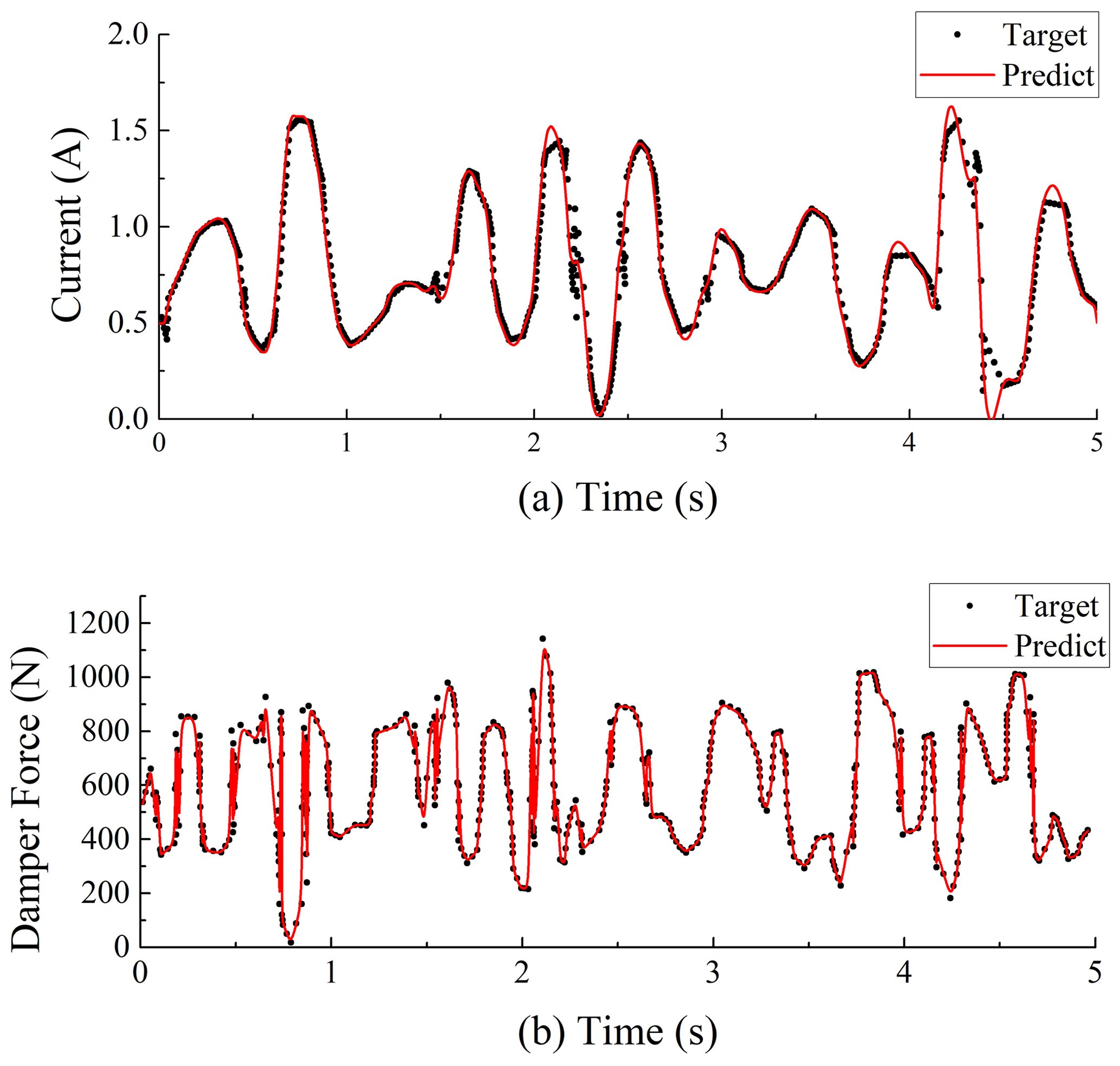
Figure 9Validation of the ANFIS inverse model of the MR damper for checking data: (a) the command current predicted by the ANFIS model and (b) the force predicted from the command current.
4.1 Agricultural tractor seat suspension model
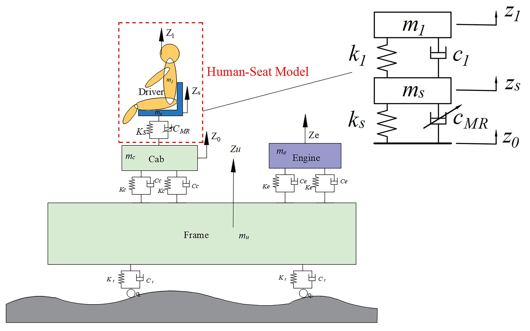
The two-degrees-of-freedom dynamic model of the MR damper seat suspension system is shown in Fig. 10. In the figure, m1 and ms represent the masses of the human body and the seat, respectively; k1 and c1 denote the stiffness and damping of the human body; ks and cMR indicate the stiffness of the seat suspension system and the equivalent damping of the MR damper, respectively; and z1, zs, and z0 represent the displacements of the human body, seat, and base input excitation, respectively.
In accordance with Newton's second law, the seat system dynamics are represented by the model illustrated in Eq. (14).
where FMR represents the damping force of the seat MR damper. According to modern control theory, Eq. (14) is rewritten into the state equation form as shown in Eq. (15).
where state variable , input variable , and output variable .
Table 4Main parameters of the human–seat model for agricultural tractors.

4.2 ADRC controller design
From the two-degrees-of-freedom human–seat model, we have the following:
where m1 denotes the human body, and k1 and c1 are fixed; by forming f in Eq. (16), Eq. (16) is converted to a second-order model:
Let , where b is the input gain whose value is unknown, b0 is the nominal value, and u is the input signal of the MR damper; let y=zs be the output of the MR damper, be the coefficients, and be the external perturbation of the MR seat dynamic system. The final equation is simplified into the following equation:
The problem of second-order ADRC is to design the feedback controller such that y tracks the reference input signal r. Replacing the true value of b with the nominal value b0 defines the total perturbation as ; then introducing the state variables x1=y and and expanding the state , Eq. (18) can be rewritten as follows:
where x1, x2, and x3 are the system state variables, and .
A linear expansion state observer (LESO) is built for Eq. (19):
By choosing a suitable observer gain β1,β2, and β3, the LESO is able to realize the real-time tracking of each state variable in the system. Taking and neglecting the estimation error of z3 on , the system can be reduced to a double-integrated series structure:
We design the PD controller as follows:
where r is the reference signal, and kp and kd are the controller gains; according to Eqs. (21) and (22), the system's closed-loop transfer function can be obtained:
The characteristic equation of LESO is subsequently identified as follows:
We select the ideal characteristic equation as follows:
where ω0 is the observer bandwidth; then we have β1=3ω0, , and .
As stated in the literature (Jin et al., 2020; Zhong et al., 2022), the parameters , kd=2ξωc, and ωc are selected as the controller bandwidth, and ξ is the damping ratio. This configuration simplifies the ADRC controller parameter selection process, as only the observer bandwidth ω0 and the controller bandwidth ωc need to be chosen. The configuration of reasonable b0, ω0, and ωc in the ADRC controller can achieve the desired performance of the dynamic control system for seat vibration damping.
4.3 Control system design
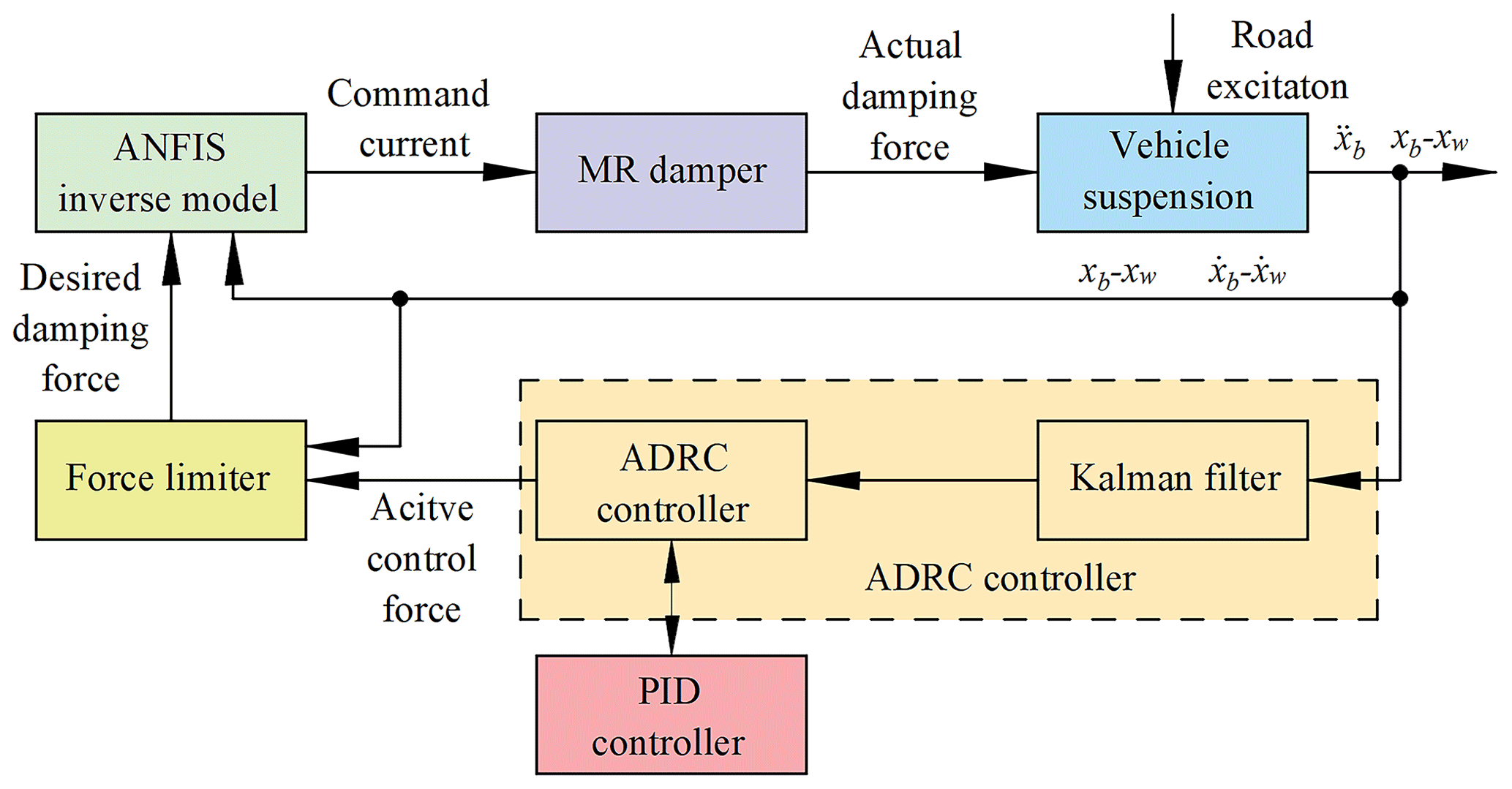
Given that the MR damper is a semi-active device, it is most appropriate to utilize a semi-active control system. The semi-active control system comprises two principal components: a system controller and a damper controller. The system controller generates the desired damping force based on the dynamic response of the suspension, while the damper controller adjusts the input current in order to track the desired damping force. The semi-active controller described in this paper comprises an ADRC controller (system controller) and an ANFIS inverse model (damper controller). To simulate the vibration of the seat suspension in a tractor cab, a structure for a vehicle suspension semi-active controller with an MR damper is constructed, as illustrated in Fig. 11. The control principle is as follows: the ADRC controller calculates the active control force based on the measured output, generates the desired damping force through a force limiter based on the active control force, and then uses the ANFIS inverse model of the MR damper to adjust the command current according to the desired damping force and vehicle suspension response. Ultimately, the requisite input current is determined through the ANFIS inverse model, with the MR damper then approximating the necessary damping force.
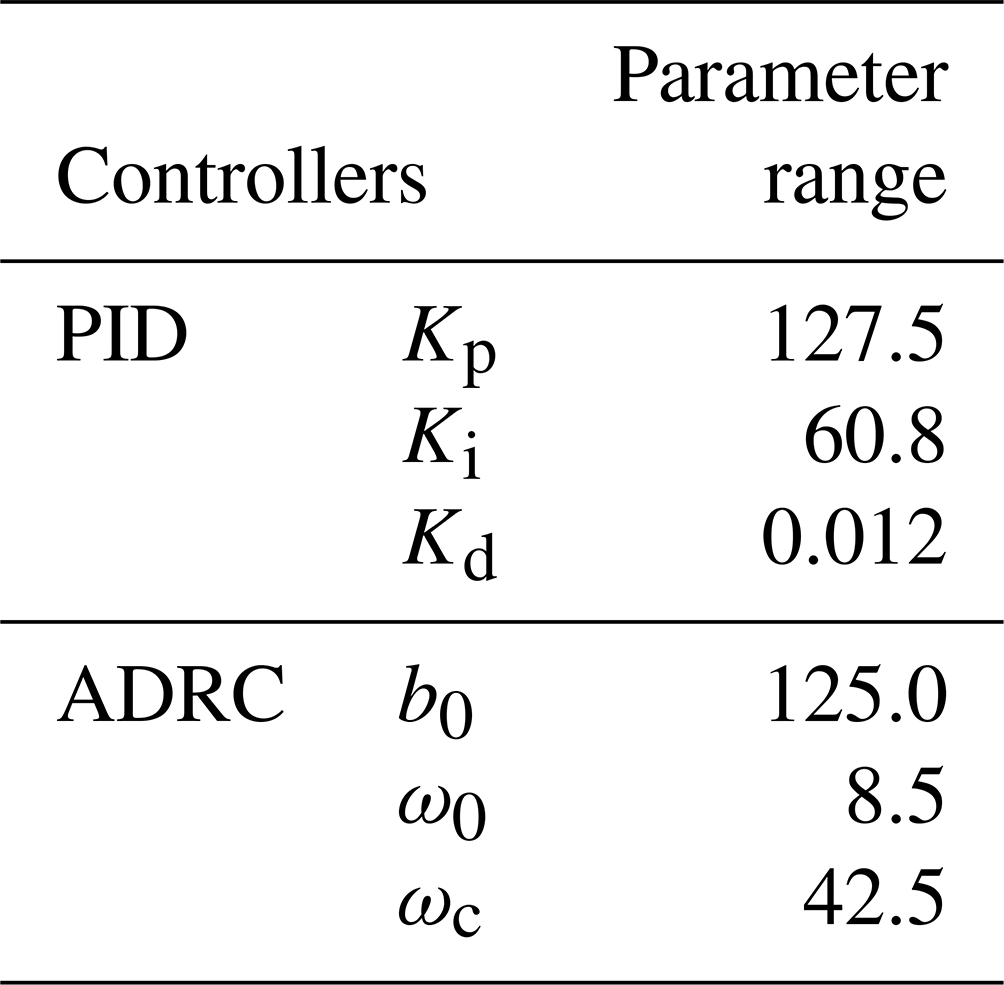
In order to ascertain the efficacy of the MR damper in seat suspension, the ADRC system was subjected to comparison with both passive control and PID control. The detailed parameter settings of the PID controller and ADRC controller are shown in Table 3.
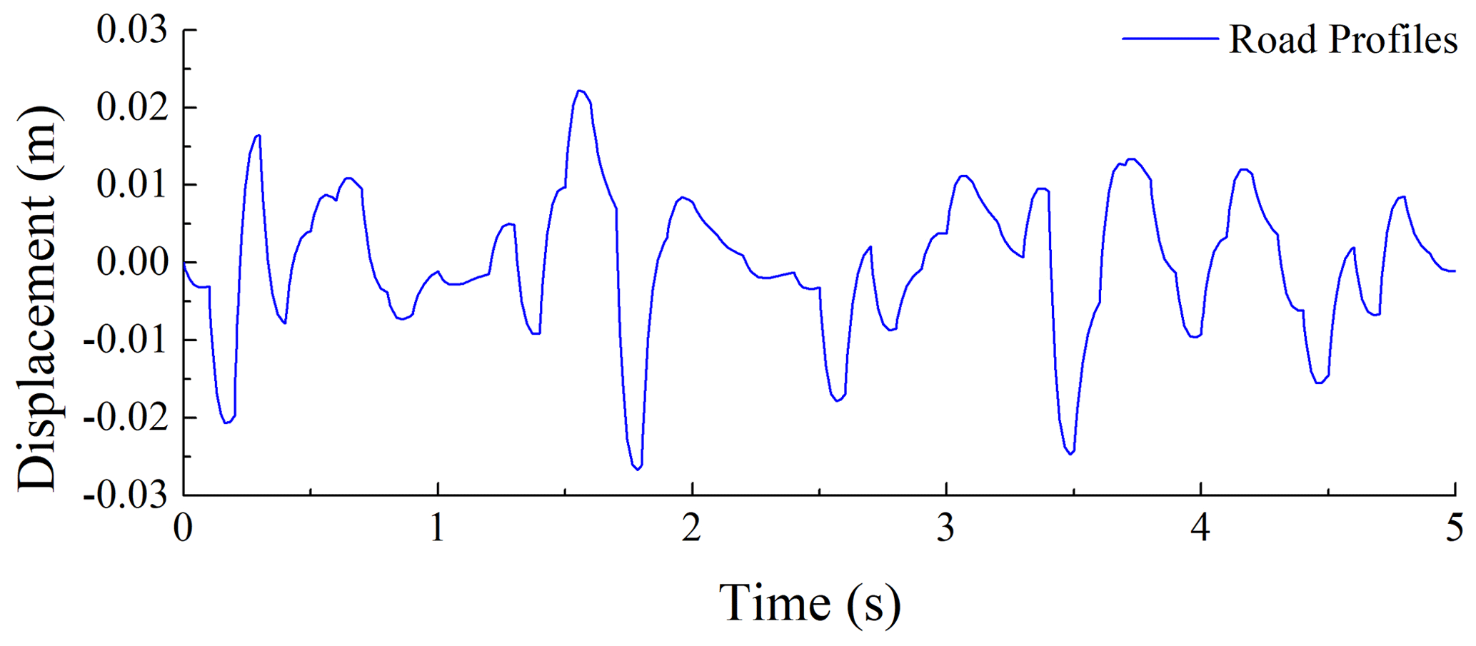
The simulation conditions assumed a tractor travelling at a speed of 10 m s−1 on an ISO C-class road profile, with road excitation taking into account the random characteristics of road conditions. In accordance with the prescribed expression for the power spectral density of the pavement outlined in GB/T 7031-2005, the mathematical model constructed in Simulink is illustrated in Eq. (26).
where ω(t) represents the Gaussian white noise signal, G0 represents the pavement unevenness coefficient, and f0 represents the cutoff frequency (0.01 Hz). For the ISO C-class road profile, take ; then the road profile simulation under v=10 m s−1 obtains the input signal as shown in Fig. 12.
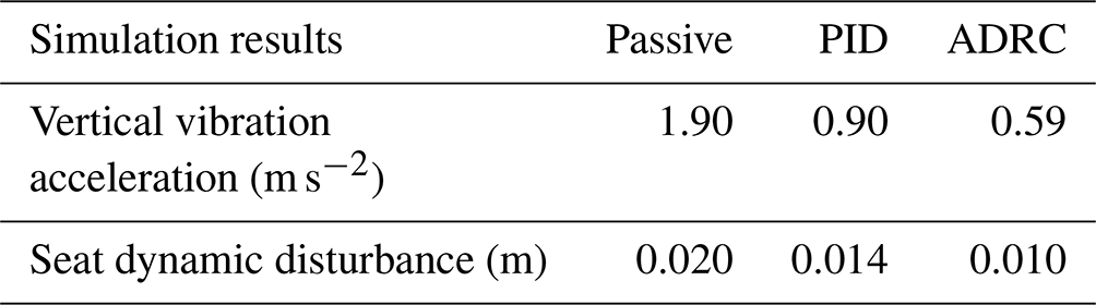
Table 4 enumerates the parameters of the seat suspension system, including the springs and dampers, along with the corresponding simulation results.
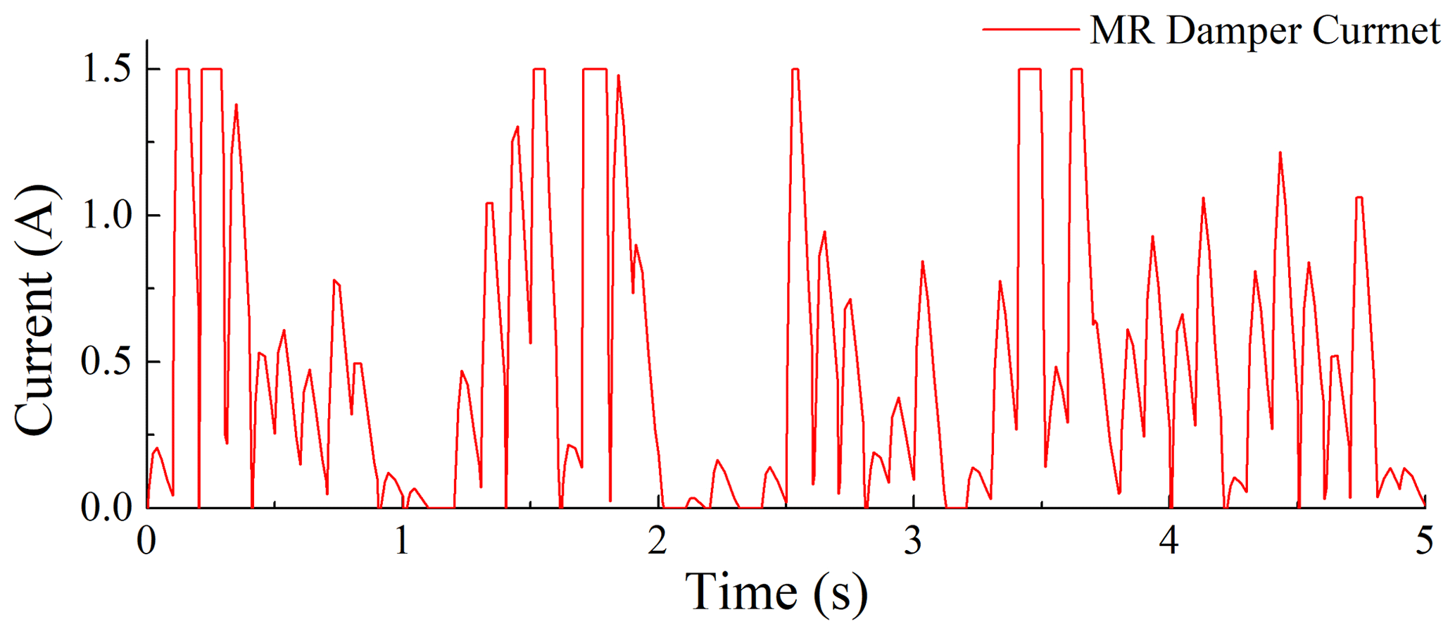
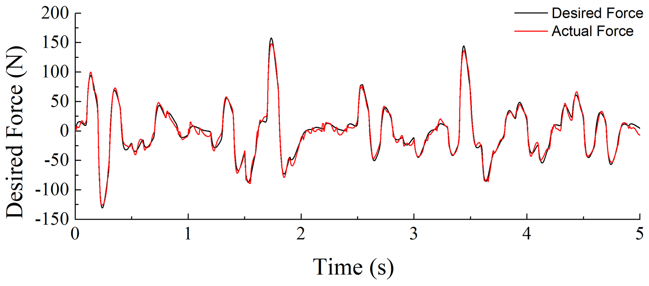
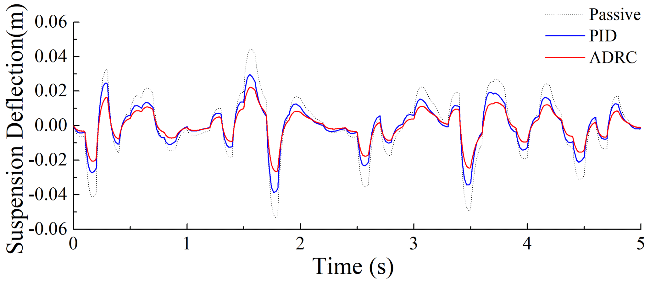
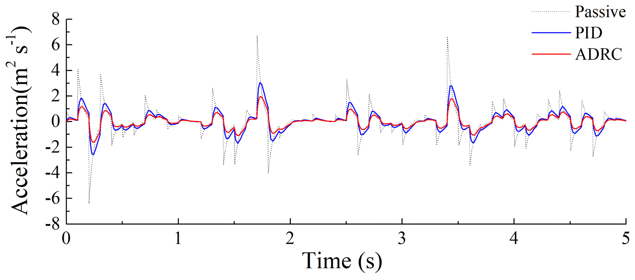
Figures 12–16 illustrate the random road profile; damping force; input current of the MR damper; and the system responses of the passive, PID control, and ADRC suspension systems under random excitation. Figure 12 illustrates the displacement of the road profile. Figure 13 illustrates the input current of the MR damper in the semi-active suspension system. Figure 14 illustrates the comparison between the actual and desired damping forces. Figures 15 and 16 illustrate that, in comparison to the passive suspension system and the PID control system, the ADRC suspension system exhibits a relatively lower vertical acceleration and seat dynamic disturbance. This evidence substantiates the efficacy of the MR damper with an ADRC controller in mitigating vibration within the suspension system. As illustrated in Fig. 14, the actual damping force generated by the MR damper exhibits a high degree of correlation with the desired damping force. This provides further confirmation of the efficacy of the ANFIS inverse model of the MR damper in controlling the damping force.
In order to gain a more comprehensive understanding of the performance advantages of ADRC in seat suspension, Table 5 lists the rms values of the relevant suspension performance indicators. As shown in Table 5, the rms value of the vertical vibration acceleration of the ADRC-controlled suspension system exhibited a notable decline of 68.9 % and 34.4 % in comparison to PID control and passive control, respectively. Additionally, the rms value of the dynamic disturbance of the ADRC-controlled suspension system demonstrated a considerable reduction of 50.0 % and 28.6 % in relation to PID control and passive control, respectively, which signifies a substantial vibration mitigation effect.
This paper proposes a novel semi-active controller that integrates ANFIS technology and ADRC, specifically designed for MR seat dampers. The article first establishes a forward dynamic model of the damper using the Bouc–Wen model based on experimental data. Then, it develops an inverse model using ANFIS technology and details the structure and training process of this inverse model. By combining the ANFIS inverse model with the designed ADRC controller, a new control scheme is proposed and applied to the seat suspension model. Numerical simulations verify the performance of the controller. The results show that this technology excels in precisely controlling the damping force, achieving continuous adjustability of the seat suspension damping, and effectively enhancing the vibration isolation effect of the seat suspension system. However, the computational complexity of ANFIS is relatively high, and the training time is lengthy. Furthermore, the combination of ANFIS and ADRC to determine the appropriate model structure parameters, such as the number and type of input affiliation functions and the number of fuzzy rules, necessitates specialized experience and experimentation. The different choices may result in a significant discrepancy in the model performance. To further enhance the performance of the control system, alternative optimization algorithms may be integrated with the ADRC algorithm.
The data that support the findings of this study are available upon request from the corresponding author.
WT and BC discussed and decided on the methodology of the study and prepared the paper. LZ and ZZ contributed to the prototype and testing. JW and MD contributed to the model building.
The contact author has declared that none of the authors has any competing interests.
Publisher's note: Copernicus Publications remains neutral with regard to jurisdictional claims made in the text, published maps, institutional affiliations, or any other geographical representation in this paper. While Copernicus Publications makes every effort to include appropriate place names, the final responsibility lies with the authors.
The authors would like to thank Fujian Key Laboratory of Big Data Application and Intellectualization for Tea Industry and the Key Laboratory for Agricultural Machinery Intelligent Control and Manufacturing of Fujian Education Institutions, which provided a favourable research environment for this study.
This research was funded by the Natural Science Foundation of Fujian Province (grant nos. 2022J011191 and 2024J01909), the Fujian Provincial Technological Innovation Key Research and Industrialization Projects (grant no. 2024XQ024) and the Nanping Science and Technology Plan Project (grant nos. N2023Z001, N2023Z002, N2023J001 and N2024Z001).
This paper was edited by Zi Bin and reviewed by two anonymous referees.
Abd Elwahed, A. A., Metered, H., and Monieb, H.: Dynamic Behavior Prediction of Magnetorheological Fluid Dampers using Neural Networks, Eur. J. Sci. Innov. Technol., 4, 249–262, 2024.
Aguirre, N., Ikhouane, F., Rodellar, J., and Christenson, R.: Parametric identification of the Dahl model for large scale MR dampers, Struct. Control Health Monit., 19, 332–347, https://doi.org/10.1002/stc.434, 2012.
Ahn, D.-V., Kim, K., Oh, J., Seo, J., Lee, J. W., and Park, Y.-J.: Optimal Control of Semi-Active Suspension for Agricultural Tractors Using Linear Quadratic Gaussian Control, Sensors, 23, 6474, https://doi.org/10.3390/s23146474, 2023.
Archakam, P. K. and Muthuswamy, S.: Design and simulation of a crash energy absorption system integrated with magneto-rheological absorber, J. Vib. Eng. Technol., 9, 1635–1656, https://doi.org/10.1007/s42417-021-00318-6, 2021.
Bahar, A., Pozo, F., Meybodi, M. R., and Karami, S.: Magnetorheological Fluid Dampers: A Close Look at Efficient Parametric Models, Struct. Control Health Monit., 2024, 6860185, https://doi.org/10.1155/2024/6860185, 2024.
Bhowmik, K. and Debnath, N.: Semi-active Vibration Control of Soft-Storey Building with Magnetorheological Damper Under Seismic Excitation, J. Vib. Eng. Technol., 12, 6943–6961, https://doi.org/10.1007/s42417-024-01292-5, 2024.
Bilgundi, S. K., Sachin, R., Pradeepa, H., Nagesh, H., Kumar, M. L. J. P., and Systems, C. o. M. P.: Grid power quality enhancement using an ANFIS optimized PI controller for DG, Protection Control of Modern Power Systems, 7, 1–14, https://doi.org/10.1186/s41601-022-00225-2, 2022.
de Brett, M., Butlin, T., and Nielsen, O. M.: Analysis of nonlinear vibration transmission through a vehicle suspension damper at low audio frequencies, J. Sound Vib., 551, 117615, https://doi.org/10.1016/j.jsv.2023.117615, 2023.
Ergin, T. and Yatak, M. Ö.: Optimal Control Method of Semi-Active Suspension System and Processor-in-the-Loop Verification, Appl. Sci., 13, 11253, https://doi.org/10.3390/app132011253, 2023.
Ghenai, C., Al-Mufti, O. A. A., Al-Isawi, O. A. M., Amirah, L. H. L., and Merabet, A.: Short-term building electrical load forecasting using adaptive neuro-fuzzy inference system (ANFIS), J. Build. Eng., 52, 104323, https://doi.org/10.1016/j.jobe.2022.104323, 2022.
Gong, W., Tan, P., Xiong, S., and Zhu, D.: Experimental and numerical study of the forward and inverse models of an MR gel damper using a GA-optimized neural network, J. Intel. Mat. Syst. Str., 34, 2172–2191, https://doi.org/10.1177/1045389X231168774, 2023.
Jiang, R., Rui, X., Wei, M., Yang, F., Zhu, H., and Gu, L.: A phenomenological model of magnetorheological damper considering fluid deficiency, J. Sound Vib., 562, 117851, https://doi.org/10.1016/j.jsv.2023.117851, 2023.
Jiménez, R. and Álvarez-Icaza, L.: LuGre friction model for a magnetorheological damper, Struct. Control Health Monit., 12, 91–116, https://doi.org/10.1002/stc.58, 2005.
Jin, H., Song, J., Lan, W., and Gao, Z.: On the characteristics of ADRC: A PID interpretation, Science China, Info. Sci., 63, 209201, https://doi.org/10.1007/s11432-018-9647-6, 2020.
Karaboga, D. and Kaya, E.: Adaptive network based fuzzy inference system (ANFIS) training approaches: a comprehensive survey, Artif. Intell. Rev., 52, 2263–2293, https://doi.org/10.1007/s10462-017-9610-2, 2019.
Kumar, J. and Bhushan, G.: Development of a hybrid vibration isolator for better ride comfort and vehicle stability, J. Braz. Soc. Mech. Sci. Eng., 46, 133, https://doi.org/10.1007/s40430-024-04711-6, 2024.
Lu, J., Sun, X., and Wong, P. K.: Neural network fuzzy control for semi-active suspension system with multi-modal switchable damping strategy, International Conference on Electric Vehicle and Vehicle Engineering (CEVVE 2023), 15–19, https://doi.org/10.1049/icp.2023.3346, 2023.
Luan, G., Liu, P., Ning, D., Liu, G., and Du, H.: Semi-active vibration control of seat suspension equipped with a variable equivalent inertance-variable damping device, Machines, 11, 284, https://doi.org/10.3390/machines11020284, 2023.
Miao, Y., Rui, X., Wang, P., Zhu, H., Zhang, J., and Wang, J.: Nonlinear dynamic modeling and analysis of magnetorheological semi-active suspension for tracked vehicles, Appl. Mathe. Modell., 125, 311–333, https://doi.org/10.1016/j.apm.2023.09.027, 2024.
Tantray, M.: A case study of magnetorheological damper models with experimental confirmation, Pract. Periodic. Struct. Design Construct., 28, 04023028, https://doi.org/10.1061/PPSCFX.SCENG-1288, 2023.
Wang, A., Ji, X., Zhu, Y., Wang, Q., Wei, X., and Zhang, S.: Tillage depth regulation system via depth measurement feedback and composite sliding mode control: A field comparison validation study, Measure. Control, 57, 685–702, 2024.
Wei, S., Wang, J., and Ou, J.: Method for improving the neural network model of the magnetorheological damper, Mechan. Syst. Signal Proc., 149, 107316, https://doi.org/10.1016/j.ymssp.2020.107316, 2021.
Xie, W. and Hua, Y.: Structural Vibration Comfort: A Review of Recent Developments, Buildings, 14, 1592, https://doi.org/10.3390/buildings14061592, 2024.
Zhao, X., Wu, S., and Pan, H.: A hybrid model of magnetorheological dampers based on generalized hysteretic biviscous operators, J. Intel. Mat. Syst. Struct., 29, 2979–2985, https://doi.org/10.1177/1045389X18781051, 2018.
Zhao, Y., Chen, X., Miao, J., Li, J., and Liu, C.: Sensitivity analysis of magnetorheological damper parameters based on the Bingham model, Int. J. Dynam. Control, 12, 2717–2731, https://doi.org/10.1007/s40435-024-01401-y, 2024.
Zhong, S., Huang, Y., and Guo, L.: An ADRC-based PID tuning rule, Int. J. Robust Nonl. Control, 32, 9542–9555, https://doi.org/10.1002/rnc.5845, 2022.
- Abstract
- Introduction
- The Bouc–Wen model for MR dampers
- ANFIS inverse dynamics modelling
- Semi-active seat suspension control design for agricultural tractors
- Simulation and analysis
- Conclusions
- Data availability
- Author contributions
- Competing interests
- Disclaimer
- Acknowledgements
- Financial support
- Review statement
- References