the Creative Commons Attribution 4.0 License.
the Creative Commons Attribution 4.0 License.
 | 23 Jan 2024
Design and analysis of a dual-rope crawler rope-climbing robot
Jinhang Wang
Lairong Yin
Ronghua Du
Long Huang
Juan Huang
A rope-climbing robot (RCR) can reciprocate on a rope. To address the problems of poor load capacity and adaptability of the existing RCR, this study designs a dual-rope crawler type RCR, which can be used as a new type of transportation equipment in hilly, mountainous, and plateau areas. The crawler rope-climbing mechanism is a combination of a chain drive and the rope-climbing foot. Innovatively applying the parabolic theory of overhead rope to kinematically analyze the rope-climbing robot system, the robot motion trajectory model and the tilt angle equation are established. To establish the safe working interval of the rope-climbing robot, the influence of machine load and rope span on robot tilt angle is compared. Furthermore, research on the dynamic characteristics of the rope-climbing robot is carried out, establishing a time-varying system model of the dynamic tension of the rope in the rope-climbing robot system and analyzing the effects of speed and load on the dynamic tension of the rope and system stability. Finally, the prototype test results show that the RCR operates stably and has good load capacity and barrier-crossing capability.
- Article
(13067 KB) - Full-text XML
-
Supplement
(43076 KB) - BibTeX
- EndNote


The main constraint on the development of hilly, mountainous, and plateau areas is the traffic limitation caused by the terrain, and thus the development of intelligent transportation equipment is an important force to help the development of hilly, mountainous, and plateau areas. The rope-climbing robot (RCR) is a transportation carrier that can reciprocate on a rope, which can effectively overcome the impact of complex terrain. RCRs have the advantages of simple equipment maintenance, high transportation efficiency, and high reliability, which can be widely used in agricultural transportation and equipment transportation in hilly, mountainous, and plateau terrain. Furthermore, RCRs can also be expanded to be applied in the fields of disaster rescue and power cable inspection (Küçük et al., 2022; Boufares et al., 2022; Qin et al., 2022). The rope-climbing mechanism is the key part of the RCR design. According to the kind of rope-climbing mechanism, the existing RCRs can be divided into friction wheel type (Tang et al., 2022; Yoo et al., 2021), leg type (Chen et al., 2023; Fu et al., 2022; Yu et al., 2021), roller type (Fakhari and Mostashfi, 2019; Yue et al., 2017), and continuous type (Li et al., 2019; Zheng and Ding, 2019; Cho et al., 2017). The friction wheel type RCR is based on the Hertzian contact model which is mainly used for aerial work and rescue. Through the frictional contact action of the automatic friction wheel and the rope, it realizes the automatic lifting and lowering on the vertical upright surface. The leg type RCR which is based on the bionic principle to imitate the climbing of apes has good adaptability to the size of the rope and the environment but has poor load-bearing capacity. The roller type RCR is based on the friction drive between the roller surface and the rope and has a fast travel speed, but the requirements for the rope environment are high. The continuous type RCR is based on the continuous rolling mechanism of a friction drive and has a smooth operation. Moreover, the continuous type RCR has high structural requirements, and the load capacity is closely related to the friction drive interface. Yue et al. (2017) established the quasi-static model of the RCR and the contact mechanics of the wheels to further investigate the climbing ability of robots with different wheel structures and different attitudes. Xiao et al. (2018) designed a new RCR with four arms and established the robot kinematic equations based on human tree-climbing bionics and then analyzed the climbing ability and obstacle-crossing ability to verify the feasibility of the mechanism design. Jiang et al. (2019) proposed a robust stabilization control method for RCR by dynamically controlling the clamping force in the jaws of the robot's dual arms. Cai et al. (2023) propose a robust concurrent topology optimization method by considering dynamic load uncertainty based on the bidirectional evolutionary structural optimization method. Chao et al. (2023) designed a walking fixture mechanism for RCR to achieve stable locomotion and obstacle-crossing capabilities. Therefore, the structural design of RCR is an important research direction, which is the prerequisite for the stable operation of robots. Guo et al. (2018) used the energy method and the equivalent constant method to establish the dynamic tension and deformation of ropes during the lifting process of the mine friction hoist system. Ghen et al. (2018) established a coupling model, while RCR is detached from the rope, based on the lateral vibration model of the rope and the physical structure of the robot. Alhassan et al. (2019) used a Lagrange equation to establish the robot-rope coupling mechanism and to investigate the effect of wind on the system. Marta (2021) established a dynamic tension calculation method for multi-span cableway ropes based on numerical analysis. Ma et al. (2023) presented a self-optimized artificial neural network methodology as an endeavor to discover more accurate and robust models which can simulate the interaction process between complex geometries. However, in order to solve the transportation problems in hilly, mountainous, and plateau complex terrains, it is necessary to develop a rope-climbing robot with high adaptability, good load-carrying capacity, and high stability. Meanwhile, the kinematics and stability of rope-climbing robots should be studied and analyzed to better adapt to the demand of engineering application of rope-climbing robots.
In this study, a dual-rope crawler RCR that can reciprocate on the rope was designed based on the principle of a continuous rope-climbing mechanism. The crawler rope-climbing mechanism consists of a combination of a chain drive and the rope-climbing foot. The RCR engineering prototype was produced and the field tested. The RCR motion trajectory and the robot tilt angle are studied during robot operation based on the overhead rope parabolic theory. The YOLOv5 algorithm was used to complete the identification of the robot prototype trajectory to verify the accuracy of the robot motion trajectory equations under different load cases. The effect of load and span on the tilt angle of the robot was investigated. A safe working space for the rope-climbing robot was established based on a robot tilt angle of less than 10∘. A time-varying system model of the dynamic tension of the rope in the rope-climbing robot system was established, and the effects of the robot-operating speed and load conditions on the system stability were investigated further.
2.1 Design of the crawler type rope-climbing mechanism
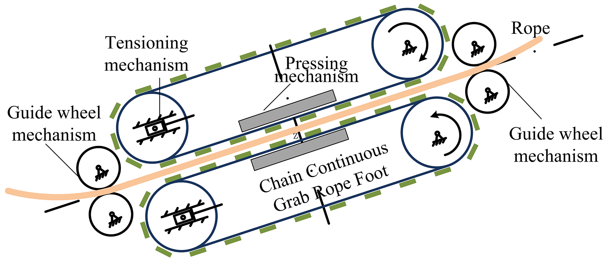
The chain drive as a motion mechanism has good adaptability, expandability, and high efficiency of motion. As shown in Fig. 1, a chain with lugs mounts the rope-climbing foot as the crawler mechanism that moves to the rope. Guide wheels are installed on the frame at both ends to form a stable rope-climbing interval. The rope-climbing interval is installed with upper and lower crawler rope-climbing mechanisms, while the rope passes through the middle. The crawler rope-climbing mechanism is equipped with a chain-tensioning device, which reduces the vibration of the chain drive and serves as the chain-guiding crawler between rope-climbing intervals. The upper chain-tensioning device converts the self-weight of the machine into a compression force to make the rope-climbing foot press against the rope. The lower chain-tensioning device can be adjusted with bolts. Therefore, a good friction transmission interface is formed between the rope-climbing foot and the rope in the rope-climbing interval. The movement of the RCR along the rope direction is realized by synchronously driving the chains in the upper and lower crawler rope-climbing mechanisms.
The load capacity of the robot is closely related to the friction force generated at the friction interface between the rope-climbing foot and the rope. From classical friction mechanics, it is known that the friction force is related to the friction surface pressure and the coefficient of friction:
where μ is the coefficient of friction between the rope-climbing foot and the rope, G is the sum of the gravity of the robot and the load, and Fpress is the clamping force provided by the pressing mechanism.
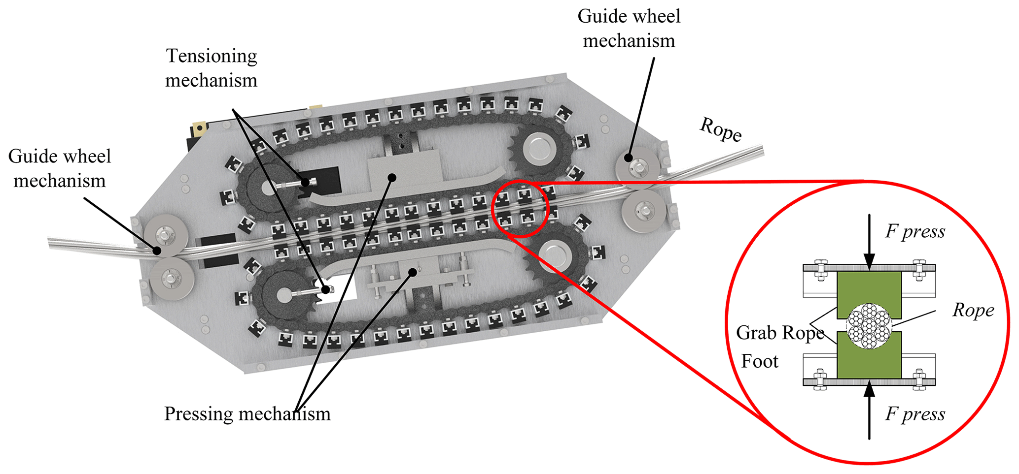
The driving force of the rope-climbing robot is the reaction force of the static friction between the rope-climbing foot and the rope, so the maximum static friction determines the maximum driving force of the rope-climbing robot. The rope-climbing foot uses rubber material whose contact surface with the wire rope is the Hertzian contact, so the maximum static friction can be increased in the form of increasing the contact area. The rope is made of a steel cable with a core, and the contoured cross section can be regarded as circular. The contact area between the planar-shaped crawler and the rope is small, so the circular rope-climbing foot structure is designed as shown in Fig. 2. Expand the contact area between the rope-climbing foot and the rope to improve the overall load capacity of the robot.
2.2 Design of the RCR mechanism
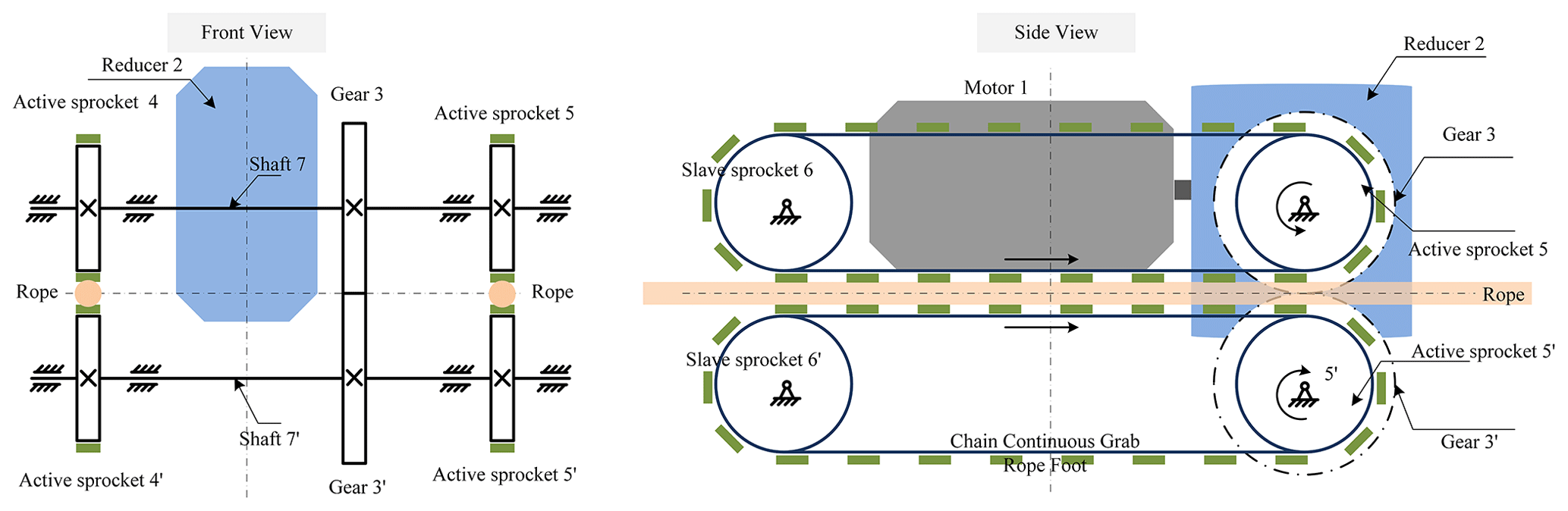
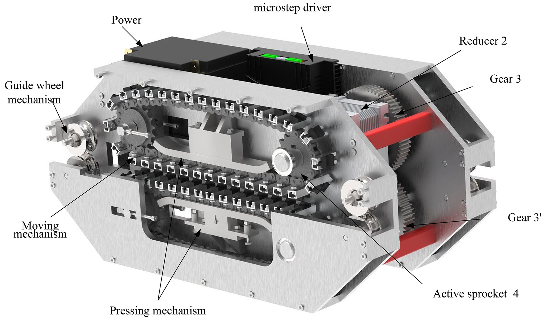
The majority of the existing RCRs adopt the form of a single rope plus a protection rope, which is prone to tilt and derailment during operation. This study designs a dual rope-crawling climbing robot with double guide ropes based on the crawling rope-climbing mechanism, which ensures the balance and stability of the robot while climbing. The mechanism principle of the robot is shown in Fig. 3, and the detailed structure of the robot is shown in Fig. 4. The output shaft of motor 1 is connected to the dual-output reducer 2 for speed reduction. The output of the reducer, the active sprockets 4 and 5, and the gear 3 are located on shaft 7. The active sprockets 4' and 5' and the gear 3' are located on shaft 7'. The transmission between shaft 7 and shaft 7' is carried out through the gears 3 and 3', which realizes the synchronous reverse rotation of the active sprockets 4 and 5 and the active sprockets 4' and 5'. Thus, the rope-climbing mechanism of the robot crawler is synchronized.
3.1 Analysis of the motion trajectory of the RCR
The RCR moves repeatedly along the overhead ropes. The overhead rope is divided into two forms, equal height pivot fixed and unequal height pivot fixed; however, their system mechanics analysis principle is the same. The double ropes in the system are considered a single rope for analysis. Suppose the load of the rope is uniformly distributed along the horizontal direction and the uniform load in the horizontal direction is . Then, the parabolic equation of the rope without load with the left pivot point as the origin can be obtained as follows:
where w is the mass of the rope, l0 is the horizontal span distance of two fixed pivot points, q is the rope horizontal direction uniform load, α is the tilt angle of the two fixed pivot points, f0 is the disturbance of the rope's midpoint, and .
Then the length of the rope between the two fixed pivot points can be obtained as
When the robot crawls on the rope, the robot is considered to act as a concentrated load on the overhead rope, and its motion trajectory is related to the ratio of robot load P to rope self-weight W.
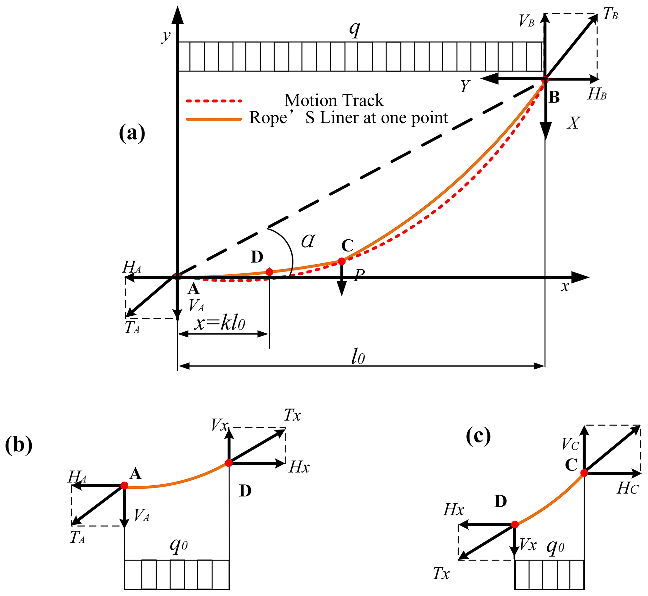
As shown in Fig. 5, when the ratio of robot load P to rope self-weight W is infinitesimal, its trajectory can be regarded as a parabola; when the ratio of robot load P to rope self-weight W is infinite, its trajectory can be regarded as an ellipse with A and B as the focal points. However, under the actual working condition, the value of the ratio of robot load P to rope self-weight W is between 0.1 and 3.0, where the above two cases do not exist, so the trajectory is between the ellipse and parabola.
When the RCR is operating, it is equivalent to a concentrated load acting on the overhead rope. The linearity of the overhead rope is shown in Fig. 5a, and the AC section and the BC section are two parabolic curves. T is the rope tension, H is the rope horizontal tension, and V is the rope vertical tension. As shown in Fig. 5b, the x–A–y coordinate system is established with the fixed pivot point A as the origin, and the separation is intercepted from a point near the A end of the AC section for analysis. Similarly, the separation is intercepted from a point near the B end of the BC section for analysis in the X–B–Y coordinate system, as shown in Fig. 5c.
The equation of the curve of the AC section is
The equation of the curve of the BC section is
where x=kl0 is the AC section and is the BC section.
Assume that the rope does not elongate before and after the robot operation. The length of the rope where there is self-weight is L, the length of the AC rope where the robot works is L1, and the length of the BC rope where the robot works is L2. We obtain the following equation.
Let x=kl0 be the horizontal coordinate of the robot at a certain position, and the trajectory equation of the robot can be obtained from Eqs. (5), (6), (7), (8), and (9).
3.2 Analysis of static mechanics and tilt angles of the RCR
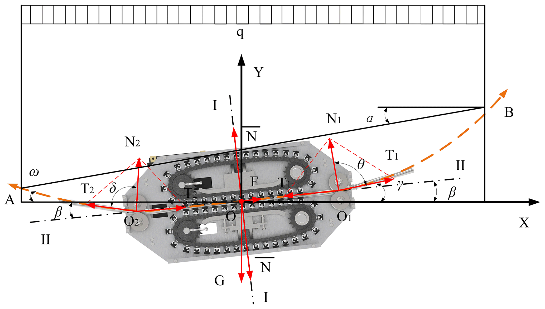
As shown in Fig. 6, the RCR is suspended from the rope by the guide wheel, and the O1O2 linear rope-climbing interval is formed between the guide wheels. Considering that the guide wheel is the slave and its friction is minimal compared to the whole machine drive, it can be neglected. The drape curve of the rope under the action of its weight q and travelling load G consists of AO2, O1B, two parabolas, and an O1O2 straight line. Furthermore, in the RCR and the horizontal direction, there is an inclination angle β, an O1B section of rope, O1 rope tension T1, the horizontal direction inclination angle γ, AO2, a section of rope O2, rope tension T2, and the horizontal direction inclination angle ω.
The coordinate system X–O–Y is established with the horizontal direction X and the vertical direction Y at the center O of the RCR. The rope force on the robot in the O1O2 linear rope-climbing area is along the I–I direction, and the rope tension T1 on both sides of the guide wheel O1 is equal. The combined force is N1, the tension T2 on both sides of the guide wheel O2 is equal, and the combined force is N2.
When the RCR is in equilibrium, T1=T2, the combined force of N1 and N2 is along the I–I direction, and the RCR tends to move along the direction. This is obtained according to the parabolic theory of the overhead ropes.
The angle γ of the RCR and rope O1B is
The angle ω of the RCR and rope AO2 is
Because the inclination angle β of the RCR is small, it can be approximated by the equation
The RCR is based on the frictional drive motion of the rope-climbing foot and the rope. The frictional force is related to the robot load and the robot tilt angle β, where the RCR drive force F should satisfy
When F<Psinβ, the RCR cannot move; when , the RCR will slip.
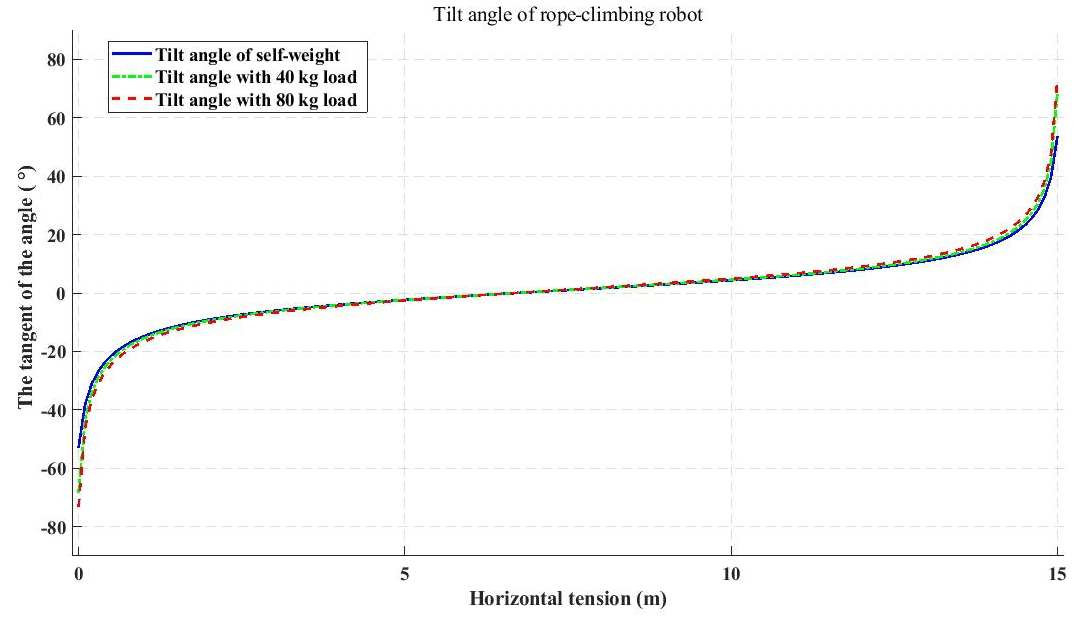
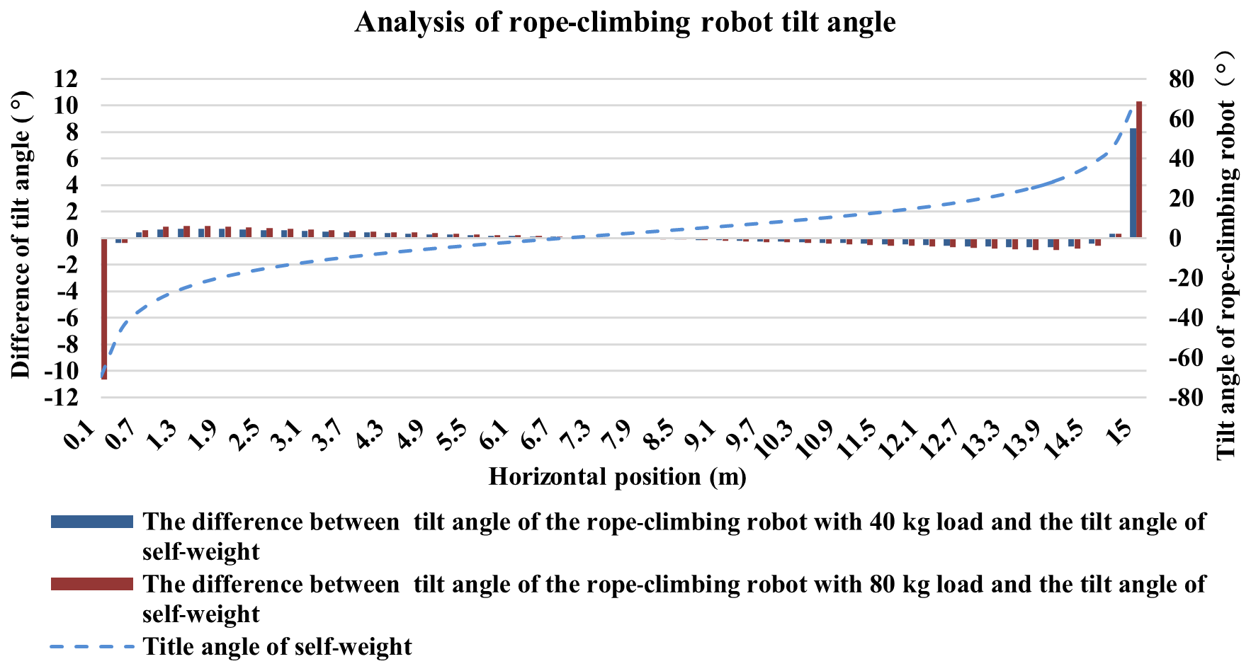
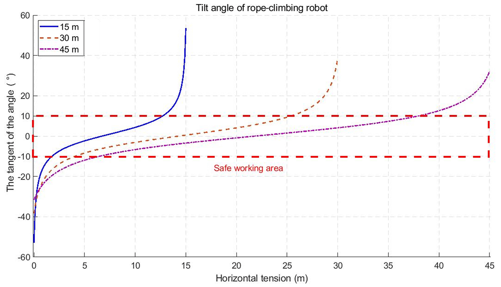
The tilt angle of the RCR is related to the location of the RCR and the ratio of robot load to rope self-weight, which impacts the motion performance of the rope-climbing robot. Based on the prototype rope-climbing robot and platform parameters in Table 2, and according to the parabolic theory of the overhead rope, the tangent value of the theoretical inclination angle of the RCR under no load, 40 kg load, and 80 kg load can be obtained as shown in Fig. 7. From the robot tilt angle a change can be seen when the rope-climbing robot is close to the fixed pivot point at both ends of the rope, the value of robot tilt angle β is the largest, and the required robot drive power is the largest. Comparing the angle of change in robot inclination for different loads in Fig. 8, the change values of robot inclination under a 40 kg load and an 80 kg load and robot inclination in the robot self-weight case can be obtained. The rope-climbing robot load case has less influence on the rope-climbing robot inclination in the middle part of the rope and has more influence when it is near the fixed pivot points at both ends of the rope. Comparing the robot inclination changes at span distances of 15, 30, and 45 m in Fig. 9, with increasing span distance, the inclination maximum decreases and the inclination changes become slower. Through the tilt angle change process and the change in tilt angle under load, the RCR in engineering applications should be considered a reasonable safe working space that should be avoided near the rope fixed pivot point area. Establish a tilt angle of less than 10∘ for the rope-climbing robot safe working space.
4.1 Theory of dynamic tension of ropes
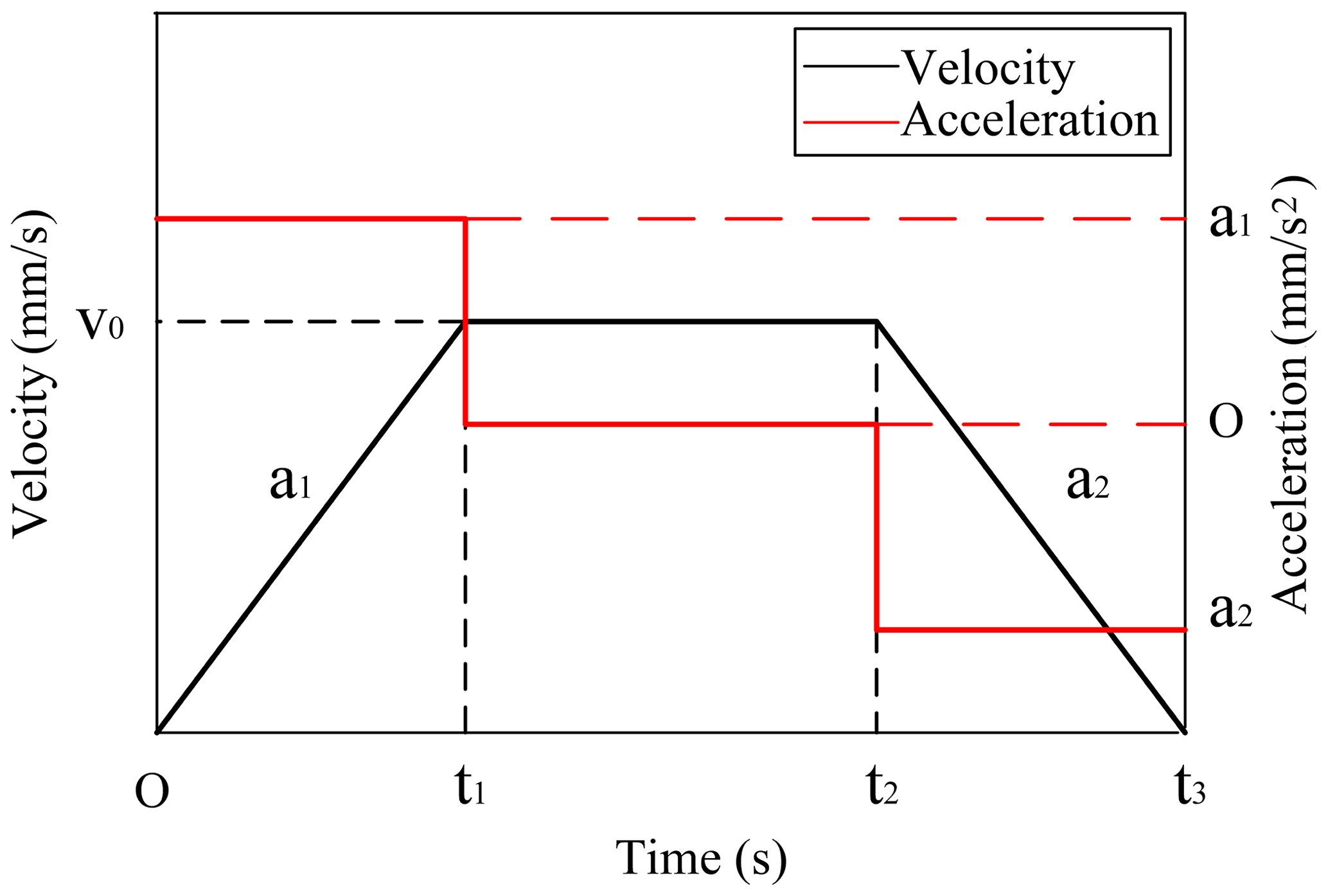
During RCR motion, the tension of the rope is an important indicator of the stability and safety for the system. The dynamics of the rope-climbing robot system is carried out to analyze the dynamic tension of the rope. The double ropes in the system are mainly for maintaining the balance of the robot. To emphasize the influence on the rope tension during the robot motion, the simplified system treats the double ropes as a single rope for analysis. As shown in Fig. 10, the RCR moves along the rope according to the law of “acceleration (a1) (0−t1) – uniform speed (v0) (t1−t2) – deceleration (a2) (t2−t3)”, only considers the influence of the RCR movement on the rope tension, and makes the following assumptions.
-
Ignore the vibration of the rope under the external disturbance.
-
Ignore the rope bending and torsional stiffness of the impact.
-
Ignore the effects of system damping and friction.
The mass of one-third of the rope is accounted for in the weight of the robot by the Rayleigh method, thus saving the rope as a massless elastomer. Taking the ropes on the left- and right-hand sides of the RCR as the object of study, the time-varying model of the dynamic tension at the fixed pivot points A and B is established.
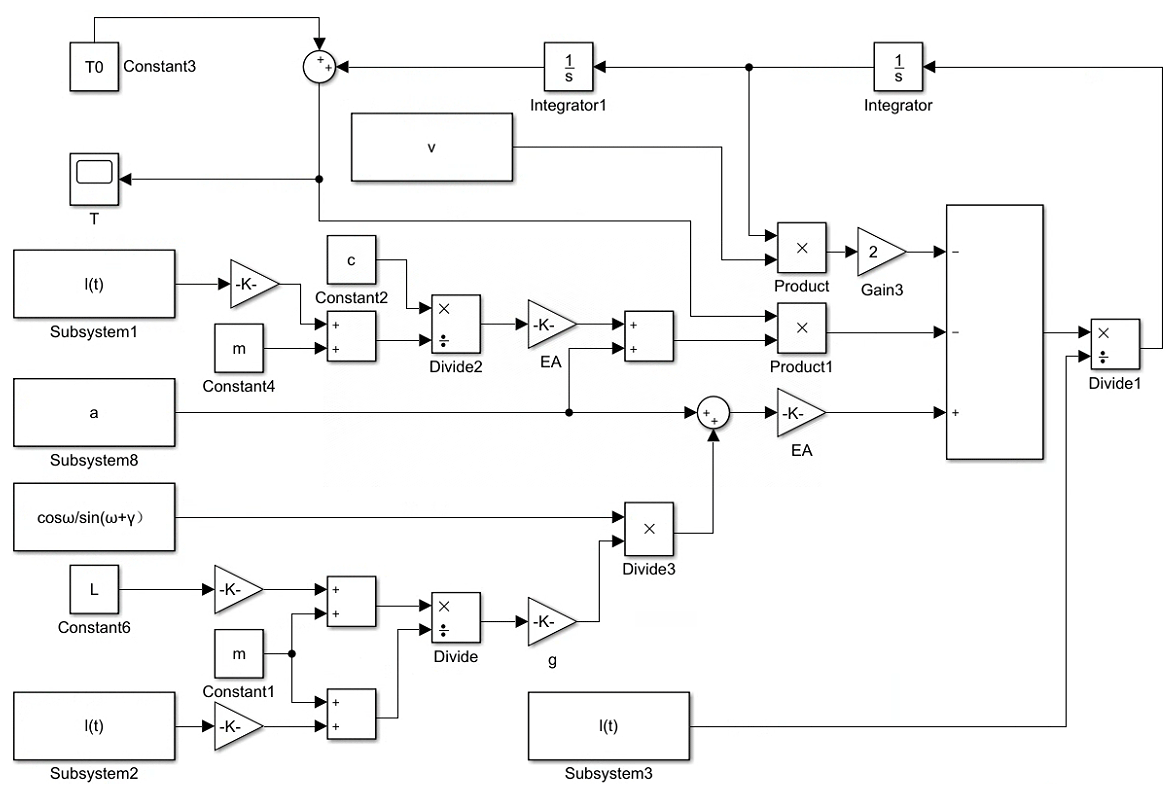
TA and TB are the tension at two points of A and B, E is the modulus of elasticity of the rope, A is the cross-sectional area of the rope, m is the mass of the robot and the load, g is the acceleration of gravity, a is the acceleration, v is the running velocity of the robot, l1(t),l2(t) is the length of the rope at the left and right ends of the robot, L is the length of the rope, and t is the time.
From Eqs. (15) and (16), rope tensions at points A and B of the rope are both significant time-varying systems, and the time-varying models at points A and B are established using MATLAB/Simulink, as shown in Fig. 11 (take the example of point A).
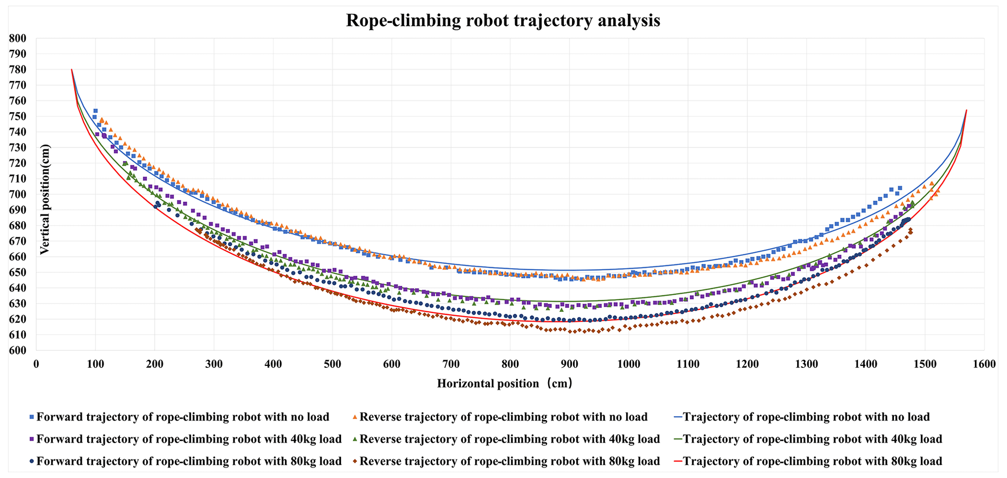
Figure 19The trajectory recognition by the YOLOv5 algorithm and the trajectory based on the overhead rope parabolic theory.
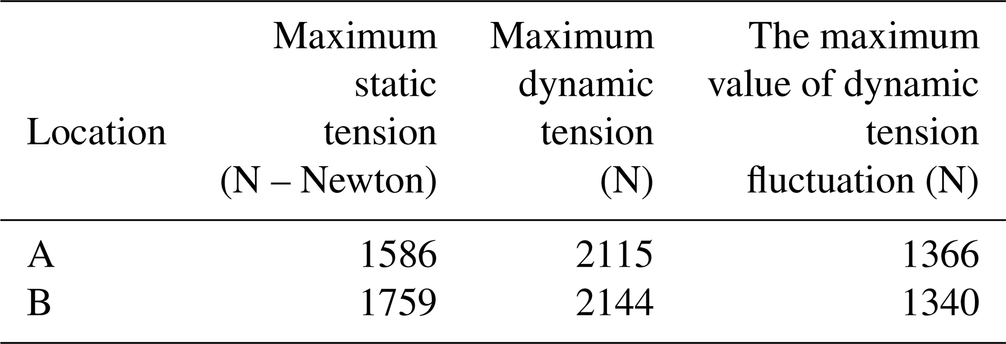
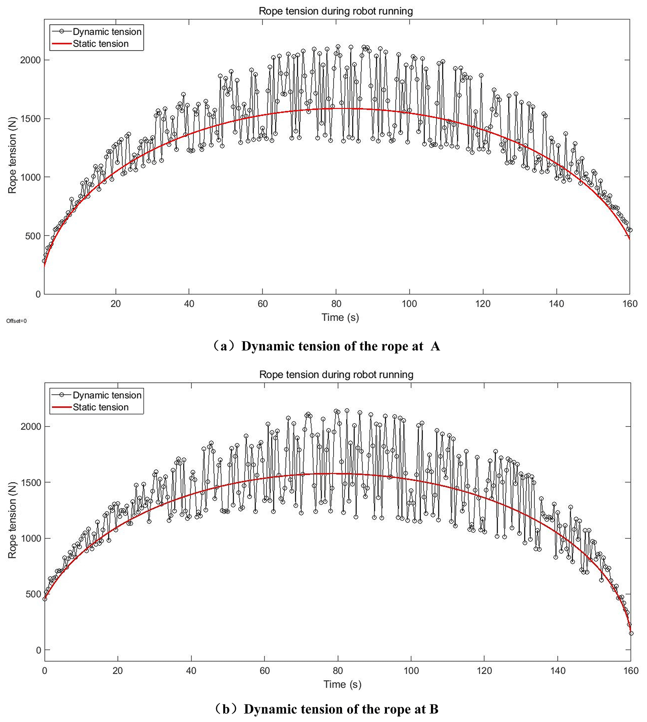
Example analysis was performed based on the prototype rope-climbing robot and platform parameters in Table 2. The analysis is carried out with the rope-climbing robot under self-weight, an acceleration of 10 mm s−2, a maximum robot speed of 100 mm s−2, an acceleration and deceleration time of 10 s, and a moving displacement of 1500 mm along the rope. From Fig. 12, at A of the rope, the maximum static tension value is 1586 N, the maximum dynamic tension value is 2115 N, and the maximum value of dynamic tension fluctuation is 1366 N. At B of the rope, the maximum static tension value is 1579 N, the maximum dynamic tension value is 2144 N, and the maximum value of dynamic tension fluctuation is 1340 N. The results show that the maximum tension of the rope reaches its maximum at the middle position, and the rope tension does not produce significant changes due to the process of acceleration change.
4.2 Simulation results of the rope dynamic tension
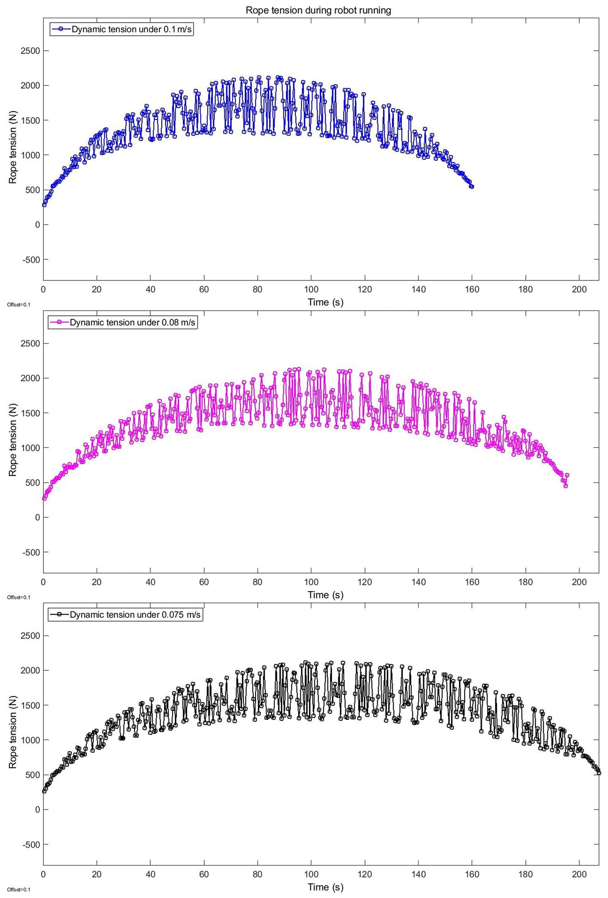
In order to research the stability of the rope-climbing robot system under different speeds of the rope-climbing robot, the rope tension changes under the speeds of 75, 80, and 100 mm s−1 are compared. From Fig. 13, it can be seen that the maximum value of dynamic tension and the maximum value of dynamic tension fluctuation at fixed pivot A of rope increases with the increase in speed.
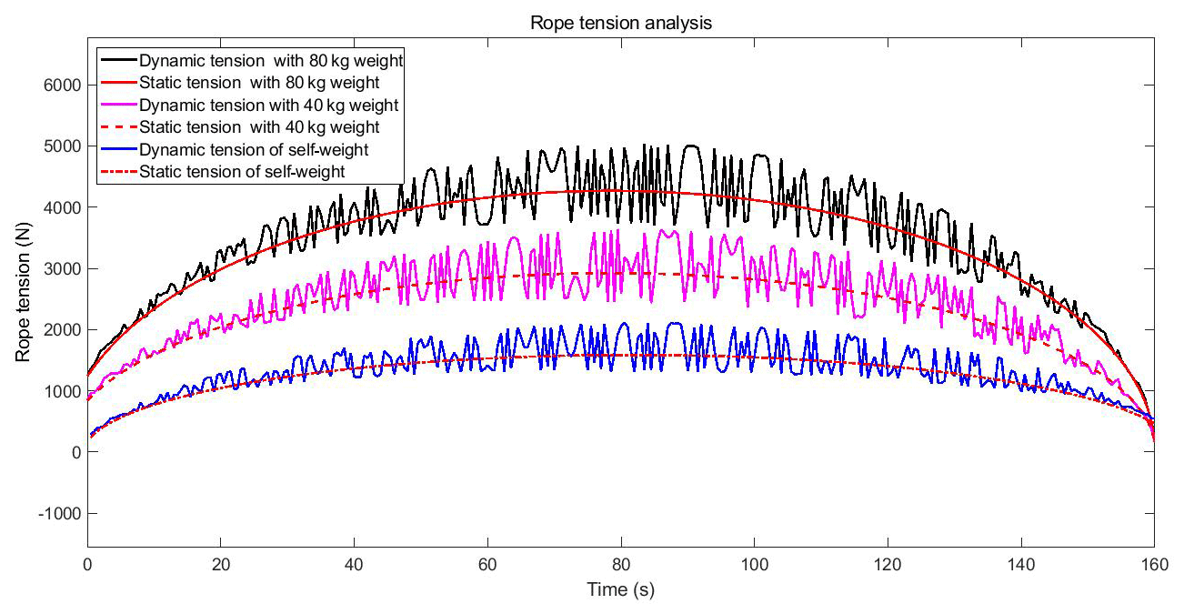
In order to research the influence of the load condition of the rope-climbing robot system on the stability of the system, we compare the rope tension variation when the robot is running at 100 mm s−1 under self-weight, 40 kg load, and 80 kg load conditions. From Fig. 14, it can be seen that the rope tension increases with the increase in load, and the maximum value of the dynamic tension fluctuation increases with the increase in load.
5.1 Development and testing of RCR prototypes
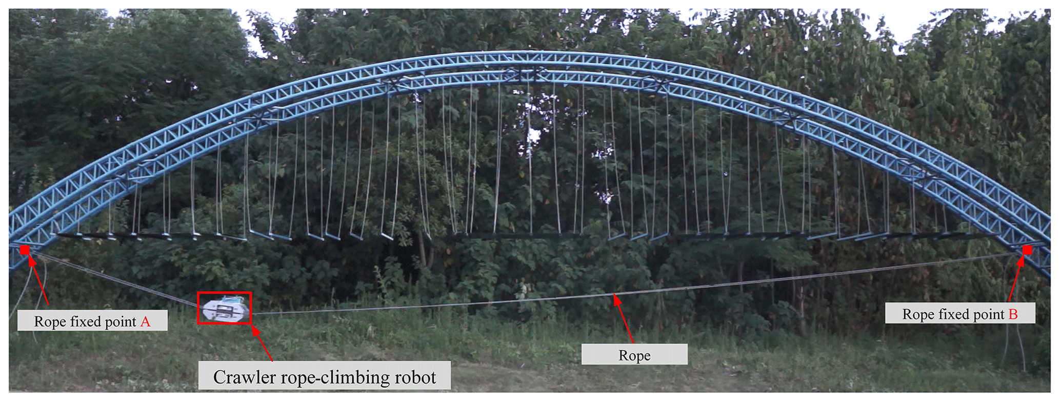
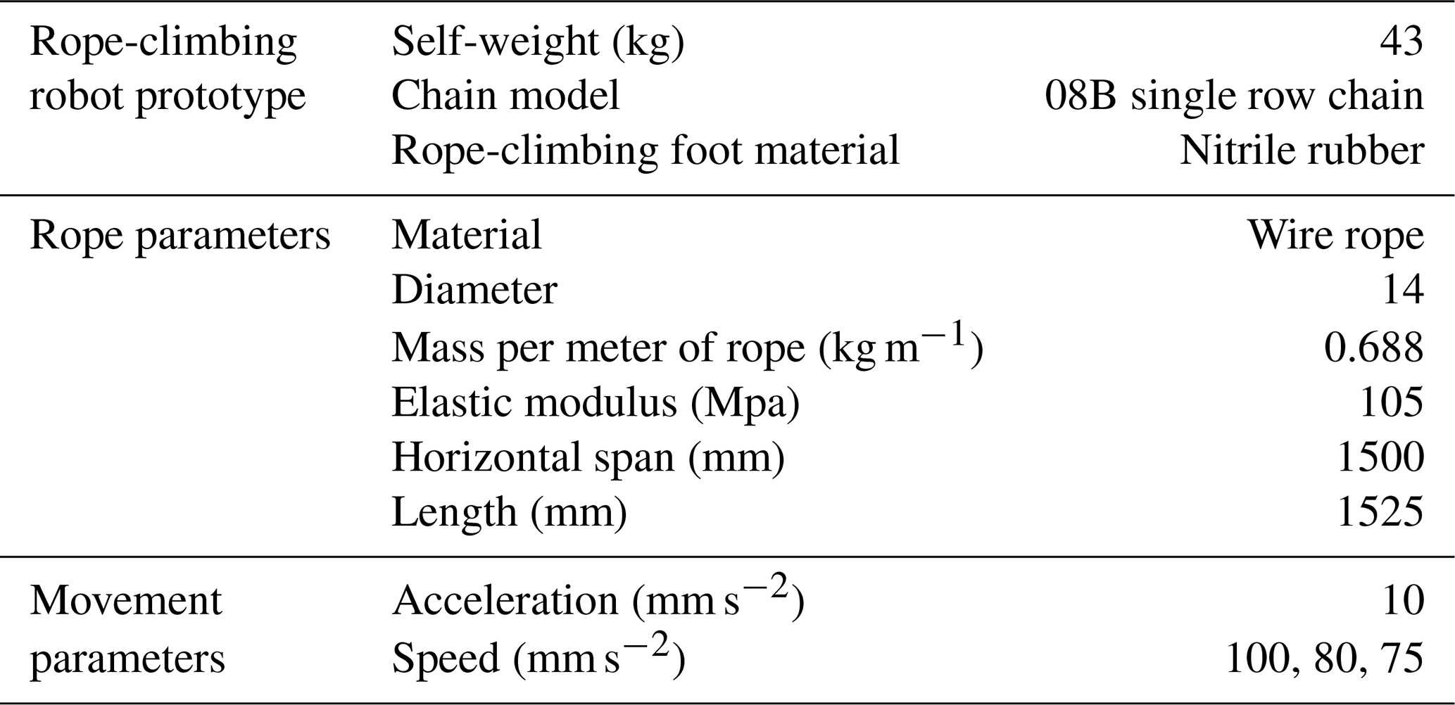
In order to test the performance of the rope-climbing robot and to carry out further research, we developed a RCR prototype. The prototype uses 86 hybrid stepper motors, the prototype weighs 43 kg and uses 14 mm diameter wire rope to build a platform with a horizontal span of 1500 mm as shown in Fig. 15, and the main technical parameters of the system are shown in Table 1.
The RCR reciprocates along the rope, with the RCR moving from a fixed pivot point of the rope to another fixed pivot point with the side of the output shaft of the reducer in the positive direction. The test results show that the maximum no-load speed of the RCR is 115.8 mm s−1 in the forward direction and 104.7 mm s−1 in the reverse direction of the RCR.
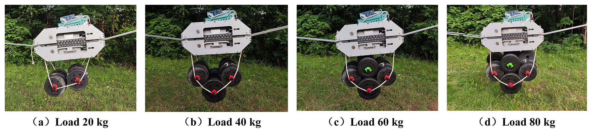
The load capacity of the RCR is an important index for evaluating the RCR. This study tested the movement effect of the RCR under the weights of 20, 40, 60, and 80 kg, respectively. It is found that the RCR runs stably under an 80 kg load; however, after exceeding 80 kg, it runs stably in the position of a gentle inclination, and when the RCR is near the position of the fixed pivot points at both ends of the rope, the robot will slip when the inclination is large.
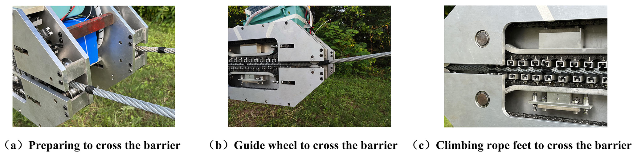
The rope will form certain obstacles on the surface of the rope due to rust and external factors. Obstacle segments of different diameters are set on the rope to test the ability of the robot to cross obstacles. The RCR prototype designed in this study grasps the rope foot inner-circle diameter of 14 mm. The test results found that the obstacle diameter is less than 17 mm and that the RCR can cross normally; however, when the obstacle diameter is 17–17.5 mm, the RCR does not pass smoothly, and when the obstacle diameter is greater than 17.5 mm, the RCR cannot pass.
5.2 Analysis of motion trajectory of the RCR
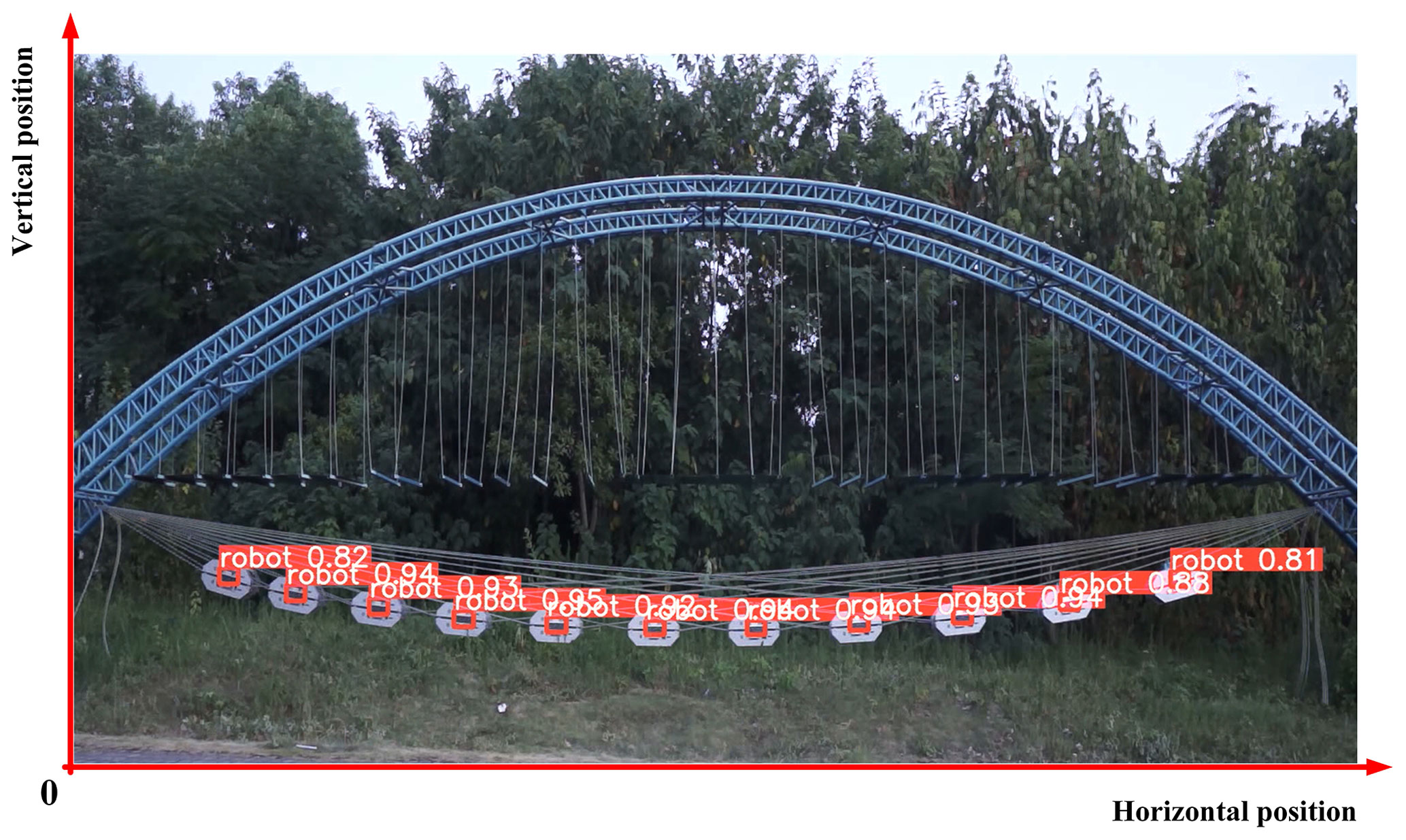
The YOLOv5 algorithm was used to obtain the trajectory of the rope-climbing robot based on the principle of monocular recognition to verify the accuracy of the parabolic theory to calculate the trajectory. The motion trajectory was recorded using a Sony NEX-5N micro-single camera with a Sony E 18–55 mm f/3.5–5.6 OSS (SEL1855) lens. During the test, the calibration of the camera internal reference and the camera external reference was firstly completed based on Zhang's calibration method. The YOLOv5 algorithm is a single-stage target detection algorithm. As shown in Fig. 18, the center point of the recognition frame of the rope-climbing robot is regarded as the center position of the robot, the lower-left corner of the recognition screen is the origin of the Cartesian coordinate system, and the Euclidean distance between the two points of the algorithm recognition center and the manual anchor frame center is taken as the recognition accuracy of the algorithm. The test results show that the average Euclidean distance is 1.2962 mm and the maximum distance is 2.3212 mm during the forward and reverse motions of the robot with an 80 kg load.
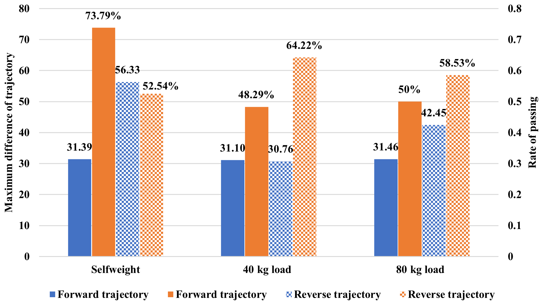
The repeated motion trajectory of the RCR with self-weight, a 40 kg load, and an 80 kg load is shown in Fig. 19. Furthermore, bringing Table 1 parameters into Eq. (10), we calculated the theoretical motion trajectory of the RCR with self-weight, a 40 kg load, and an 80 kg load. Using the difference between the actual trajectory and the theoretical trajectory within 10 mm as the reference basis, analyze the motion trajectory identified by the YOLOv5 algorithm and the theoretical motion trajectory. From Fig. 20, the maximum error of the rope-climbing robot trajectory in the case of self-weight is 31.39 mm in the forward direction and 56.33 mm in the reverse direction, and the difference between the actual trajectory and the theoretical trajectory within 10 mm is 73.39 % in the forward direction and 52.54 % in the reverse direction. The maximum error in the case of 40 kg is 31.10 mm in the forward direction and 30.70 mm in the reverse direction, and the difference between the actual trajectory and the theoretical trajectory within 10 mm is 48.29 % in the forward direction and 64.22 % in the reverse direction. The maximum error in the case of 80 kg is 31.46 mm in the forward direction and 42.45 mm in the reverse direction. The difference between the actual trajectory and the theoretical trajectory within 10 mm is 50 % in the forward direction and 58.53 % in the reverse direction. So, the maximum error between the trajectory and the overhead rope parabolic theory trajectory under different loads is 56.33 mm, and the difference between the actual trajectory and the theoretical trajectory within 10 mm is more than 48.29 %, so the motion trajectory of the RCR is in line with the motion trajectory calculated based on the overhead rope parabolic theory.
This study innovatively designs a dual-rope crawler RCR with a continuous rope-climbing mechanism in order to solve the problem of poor load capacity and poor adaptability of the existing RCR, which can reciprocate along the rope. The tracked rope-climbing mechanism is a combination of a chain drive and the rope-climbing foot. The rope-climbing mechanism utilizes a chain drive to achieve continuous rope-climbing movement. This study establishes the trajectory equation and tilt angle equation of the rope-climbing robot based on the parabolic theory of overhead rope, which is used to carry out the research on the kinematic characteristics of the rope-climbing robot. The effects of load and rope span on the tilt angle of the robot are further analyzed. According to the change in the tilt angle of the robot, it is set that the tilt angle of the robot is less than 10∘ as the safe working interval of the RCR. This study develops a time-varying system model of the dynamic tension of the rope in the rope robot system, which is used to carry out the study of the dynamic characteristics of the rope-climbing robot system. The effects of speed and load conditions on the dynamic tension of the rope during the operation of the rope-climbing robot are further analyzed. The prototype rope-climbing robot is tested and experimented. The fastest speed of the RCR reaches 115.8 mm s−1, and it can still operate stably under a load of 80 kg. The RCR can stably traverse obstacles with a diameter of less than 17 mm. The difference between the theoretical trajectories of the rope-climbing robot and the trajectories recognized by the YOLOv5 algorithm under different loads is analyzed, which verifies the validity of the parabolic theory of overhead ropes in the analysis of the dynamic characteristics of the system.
Future work will include the following: (a) research on the relationship of the RCR driving force with the friction mechanism of the rope-climbing mechanism and rope surface, together with further completion of the optimized design of the RCR; and (b) research on the dynamic characteristic response and stability of the RCR system in the case of lateral wind excitation and a sudden drop in cargo.
All the data used in the paper can be obtained on request from the corresponding author.
The supplement related to this article is available online at: https://doi.org/10.5194/ms-15-31-2024-supplement.
LY and RD proposed the idea and methodology. JW and LH derived the equations. JW and JH wrote this paper.
The contact author has declared that none of the authors has any competing interests.
Publisher's note: Copernicus Publications remains neutral with regard to jurisdictional claims made in the text, published maps, institutional affiliations, or any other geographical representation in this paper. While Copernicus Publications makes every effort to include appropriate place names, the final responsibility lies with the authors.
This work was supported by the National Natural Science Foundation of China (grant no. 52175003), the Natural Science Foundation of Hunan Province (grant no. 2021JJ30726), the Outstanding Youth Program of Hunan Education Department (grant no. 20B017), the Natural Science Foundation of Hunan Province (grant no. 2023JJ30021), and the Natural Science Foundation of Hunan Province (grant no. 2023JJ50077).
This research has been supported by the National Natural Science Foundation of China (grant no. 52175003), the Natural Science Foundation of Hunan Province (grant nos. 2021JJ30726, 2023JJ30021, and 2023JJ50077), and the Outstanding Youth Program of Hunan Education Department (grant no. 20B017).
This paper was edited by Zi Bin and reviewed by four anonymous referees.
Alhassan, A. B., Zhang, X., Shen, H., Jian, G., Xu, H., and Hamza, K. K.: Investigation of Aerodynamic Stability of a Lightweight Dual-Arm Power Transmission Line Inspection Robot under the Influence of Wind, Math. Probl. Eng., 2019, 2139462, https://doi.org/10.1155/2019/2139462, 2019.
Boufares, F., Doudech, I., and Bahrami, M. R.: Electrical Transmission Lines Robot Inspector: Design Challenges, 2022 International Conference on Industrial Engineering, Applications and Manufacturing (ICIEAM), 746–754, https://doi.org/10.1109/ICIEAM54945.2022.9787220, 2022.
Cai, J., Huang, L., Wu, H. C., and Yin, L.: Concurrent topology optimization of multiscale structure under uncertain dynamic loads, Int. J. Mech. Sci., 251, 108355, https://doi.org/10.1016/j.ijmecsci.2023.108355, 2023.
Chao, C., Mei, X., Wei, Y., and Fang, L.: A balanced walking-clamp mechanism for inspection robot of transmission line, Ind. Robot., 50, 673–685, https://doi.org/10.1108/ir-09-2022-0226, 2023.
Chen, M., Cao, Y., Tian, Y., Li, E., Liang, Z., and Tan, M.: A Passive Compliance Obstacle-Crossing Robot for Power Line Inspection and Maintenance, IEEE Rob. Autom. Lett., 8, 2772–2779, https://doi.org/10.1109/LRA.2023.3261704, 2023.
Cho, K. H., Jin, Y., Kim, H. M., Moon, H., Koo, J. C., and Choi, H. R.: Multifunctional Robotic Crawler for Inspection of Suspension Bridge Hanger Cables: Mechanism Design and Performance Validation, IEEE/ASME Trans. Mechatron., 22, 236–246, https://doi.org/10.1109/TMECH.2016.2614578, 2017.
Fakhari, A. and Mostashfi, A.: LinBot – Design, Analysis, and Field Test of a Novel Power Transmission Lines Inspection Robot, 2019 7th International Conference on Robotics and Mechatronics (ICRoM), 132–137, https://doi.org/10.1109/ICRoM48714.2019.9071839, 2019.
Fu, Q., Guan, Y., and Zhu, H.: A Novel Robot with Rolling and Climbing Modes for Power Transmission Line Inspection, 2022 IEEE/RSJ International Conference on Intelligent Robots and Systems (IROS), 7122–7128, https://doi.org/10.1109/IROS47612.2022.9981434, 2022.
Ghen, H., Zhang, X., Alhassan, A. B., Guo, J., and Xu, H.: Research on the Coupling Model for Inspection Robot to Depart from High-Voltage Transmission Line, 2018 International Conference on Sensing, Diagnostics, Prognostics, and Control (SDPC), Xi'an, China, 15–17 August 2018, 801–805, https://doi.org/10.1109/SDPC.2018.8664988, 2018.
Guo, Y., Zhang, D., Chen, K., Feng, C., and Ge, S.: Longitudinal dynamic characteristics of steel wire rope in a friction hoisting system and its coupling effect with friction transmission, Tribol. Int., 119, 731–743, https://doi.org/10.1016/j.triboint.2017.12.014, 2018.
Jiang, W., Yan, Y., Li, Q. M., Zhang, A., Li, H. J., and Jiang, D.: Research on robust stabilization control of high-voltage power maintenance robot under wind load action, Ind. Robot., 46, 870–881, https://doi.org/10.1108/ir-04-2019-0088, 2019.
Küçük, Z. K., Ekren, N., and Şahin, M.: Review of Power Transmission Line Inspection Robots Moving on Ground Wire, 2022 International Conference on Engineering and Emerging Technologies (ICEET), 1–6, https://doi.org/10.1109/ICEET56468.2022.10006846, 2022.
Li, P., Duan, X., Sun, G., Li, X., Zhou, Y., and Liu, Y.: Design and control of a climbing robot for inspection of high mast lighting, Assem. Autom., 39, 77–85, https://doi.org/10.1108/AA-01-2018-006, 2019.
Ma, J., Wang, J., Han, Y., Dong, S., Yin, L., and Xiao, Y.: Towards data-driven modeling for complex contact phenomena via self-optimized artificial neural network methodology, Mech. Mach. Theory, 182, 105223, https://doi.org/10.1016/j.mechmachtheory.2022.105223, 2023.
Marta, K. H.: Determining initial tension of carrying cable in nonlinear analysis of bi-cable ropeway – Case study, Eng. Struct., 244, 112769, https://doi.org/10.1016/j.engstruct.2021.112769, 2021.
Qin, X., Jia, B., Lei, J., Zhang, J., Li, H., Li, B., and Li, Z.: A novel flying-walking power line inspection robot and stability analysis hanging on the line under wind loads, Mech. Sci., 13, 257–273, https://doi.org/10.5194/ms-13-257-2022, 2022.
Tang, S., Huang, R., and Zhao, G.: Mechanical characteristics and experimental research of a flexible rope-sheave hoisting mechanism, J. Mech. Sci. Technol., 36, 3329–3339, https://doi.org/10.1007/s12206-022-0612-x,2022.
Xiao, S., Wang, H., and Liu, G.: Mechanism Design and Kinematic Analysis of a Novel Inspection Robot with Four Arms, Xibei Gongye Daxue Xuebao/Journal of Northwestern Polytechnical University, 36, 432–438, https://doi.org/10.1051/JNWPU/20183630432, 2018.
Yoo, S., Kim, T., Seo, M., Oh, J., Kim, J., Kim, H. S., and Seo, T.: Modeling and verification of multi-winding rope winch for facade operation, Mech. Mach. Theory., 155, 104–105, https://doi.org/10.1016/j.mechmachtheory.2020.104105, 2021.
Yu, S., Ye, C., Tao, G., Ding, J., and Wang, Y.: Design and analysis of a modular rope-climbing robot with the finger-wheeled mechanism, J. Mech. Sci. Technol., 35, 2197–2207, https://doi.org/10.1007/s12206-021-0436-0, 2021.
Yue, X., Wang, H., and Jiang, Y.: A novel 110 kV power line inspection robot and its climbing ability analysis, Int. J. Adv. Rob. Syst., 14, 172988141771046, https://doi.org/10.1177/1729881417710461, 2017.
Zheng, Z. and Ding, N.: Design and Implementation of CCRobot-II: a Palm-based Cable Climbing Robot for Cable-stayed Bridge Inspection, 2019 International Conference on Robotics and Automation (ICRA), Montreal, Canada, 20–24 May 2019, 9747–9753, https://doi.org/10.1109/ICRA.2019.8793562, 2019.
- Abstract
- Introduction
- Design of the dual-rope crawler rope-climbing robot
- Analysis of the motion trajectory and tilt angle of the RCR
- Analysis of rope dynamic tension
- Development and analysis of RCR prototypes
- Conclusions
- Data availability
- Author contributions
- Competing interests
- Disclaimer
- Acknowledgements
- Financial support
- Review statement
- References
- Supplement