the Creative Commons Attribution 4.0 License.
the Creative Commons Attribution 4.0 License.
 | 18 Apr 2024
Dynamic modeling and performance analysis of the 2PRU-PUU parallel mechanism
Tianze Sun
Wei Ye
Chao Yang
This paper investigates the dynamic modeling and performance analysis of the 2PRU-PUU reconfigurable parallel mechanism (RPM); here, P, R, and U denote the prismatic, revolute, and universal joints, respectively. By altering one of the rotation axes of the reconfigurable universal joint in limb 3, the mechanism can be switched into two operation modes, 1R2T and 2R1T. The authors resort to the Lagrangian equations of the first kind to derive the dynamic model of the 2PRU-PUU RPM. The optimal driving force distribution is determined to solve the problem of the non-uniqueness solution in dynamic analysis. The dynamic formulations are verified with the results obtained in ADAMS software. The dynamic manipulability ellipsoid index, which offers a quantitative assessment of the ability in manipulating the end effector, is used to assess the dynamic performance of the mechanism. Then, the distribution characteristics of the rotational and translational dynamic performance of the RPM are derived.
- Article
(1945 KB) - Full-text XML
- BibTeX
- EndNote


Due to the positioning accuracy, excellent dynamic performance, and high stiffness (Hu et al., 2020a; Yang et al., 2022), the parallel mechanism (PM) has been widely applied in many fields, such as the Tricept (3-UPS+UP) PM (Kureková and Halaj, 2014), the Z3 head (3-PRS) (Chen et al., 2014), the serial–parallel robotic arm (3RPS+3SPR) (Hu et al., 2019), and the Exechon hybrid manipulator (Hu et al., 2020b). However, traditional PMs cannot meet the needs of multiple task requirements in the modern automation field, so PMs with multi-operation modes (Ye et al., 2014; Li and Herve, 2009), also called reconfigurable PMs (RPMs), have become a research hotspot.
The primary characteristics of RPMs are as follows: (a) fewer actuators are needed for the moving platform to realize several motion patterns, and (b) reconfiguring the PM does not require disassembly of the PM. There have been several classes and a general method for the type synthesis of RPMs (Kong, 2013; Liu and Liu, 2022), and scholars have done lots of research on reconfigurable analysis (Carbonari et al., 2019; Kong, 2014). However, previous research only focused on the type synthesis and kinematics; research on the dynamics of RPM is quite limited.
The foundation of dynamic performance analysis for PMs is an accurate dynamic model, which is also an essential prerequisite for realizing parameter optimization and high-precision, high-efficiency control of PMs. However, dynamic analysis is more challenging than kinematic analysis because of the difficulty in describing the overall mass metrics caused by the multiple closed-loop properties of PMs. Typical dynamic modeling can be directly computed in each configuration because each configuration can be thought of as a typical PM with a fixed number and type of operation modes. Currently, the Newton–Euler method (Gan et al., 2016), the Lagrange method (Karimi Eskandary and Angeles, 2018), the principle of virtual work (Pedrammehr et al., 2018), and the Kane equation (Elgolli et al., 2019) are the main methods for the dynamic modeling of PMs.
In the reported literature, redundant actuated PMs possess many advantages, such as extended reachable workspace (Arata et al., 2011), elimination or reduction of singularities, and increased stiffness (Hu et al., 2012; Zhao et al., 2009). However, there are also some challenges introduced by redundant actuators such as the non-uniqueness solution in dynamic analysis, which is caused by the fact that the number of equations is always less than the number of unknown variables, and thus the dynamic equation cannot be solved uniquely. In recent years, the Newton–Euler method has been used to investigate the dynamic mode of a 3-degree-of-freedom (DOF) redundantly actuated parallel manipulator by taking the flexible deformation of the limbs into account (Li et al., 2016). The forward and inverse dynamics formulations of the 3-RRR PM were developed using the Jacobian/Hessian matrices of the constraint equations, the Lagrange–D'Alembert equation, and the Hessian matrix of the kinetic energy of the manipulator (Abo-Shanab, 2020). Based on the virtual work method, an improved general dynamic formulation of the inverse and direct dynamics of the 6-UPS Gough–Stewart PM was presented (Kalani et al., 2016). Wang et al. (2019) resorted to the natural orthogonal complement based on an adaptation of screw theory to derive the dynamics model of the 2PUR-2RPU PM.
The dynamic manipulability ellipsoid (DME) index (Chen et al., 2021; Chiacchio, 2000) is used to evaluate the dynamic performance of the proposed RPM, namely the easiness of arbitrarily changing the position or orientation of the end effector of PMs. The distribution characteristics of both rotational and translational dynamic performance are obtained in an intuitive manner (Yoshikawa, 1990; Chen et al., 2017). The adopted dynamic modeling method and dynamic performance analysis will provide a basis for structural optimization and motion control of the subsequent prototype.
The main contribution of this work is the dynamic modeling of the reconfigurable PM based on the Lagrange method, which has the benefit of being able to handle the motion of the mechanism uniformly under various operation modes. The proposed dynamic model serves as a valuable tool for control algorithm and performance optimization of RPMs.
This paper is organized as follows: in Sect. 2, the structure description of the 2PRU-PUU RPM is presented. In Sect. 3, position analysis of the proposed RPM is conducted. In Sect. 4, dynamic modeling is established by the Lagrange method first, then the driving force distribution of redundant actuator PMs is proposed, and finally the correctness of the dynamic models is verified by ADAMS simulation software. In Sect. 5, the DME index is calculated within the workspace of the PM. In Sect. 6, some concluding remarks and directions for future work are summarized.
As shown in Fig. 1, PM is composed of a moving platform, a fixed platform, two identical PRU limbs, and a PUU limb. In PRU limbs, the two-P pair has the same axis and is perpendicular to the axis of the P pair in the PUU limb, and the direction of the R pair axis is the same as the first rotational axis of the U joint connected to the moving platform. In the PUU limb, the second rotation axis of the lower U joint is parallel to the first rotation axis of the upper U joint, and the first rotation axis of the lower U joint is parallel to the R pair axis in the PRU limb and the second rotation axis of the upper U joint in the PUU limb. Three limbs connect the fixed and moving platform at point Pi and Bi with prismatic pairs and universal joints, respectively. Coordinate frames and are linked to the fixed platform and moving platform, respectively.
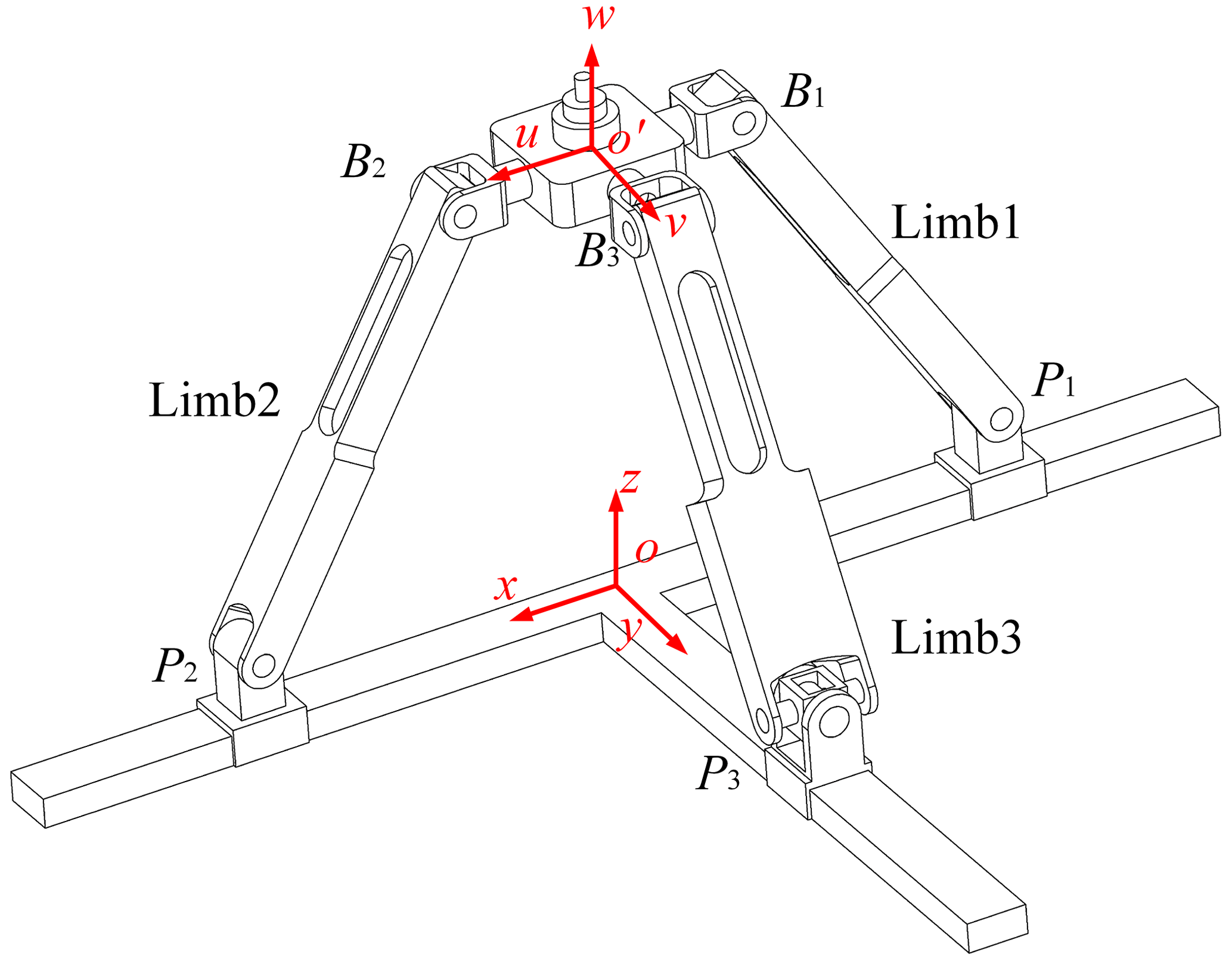
From the switch configuration, the RPM can evolve into two diverse configurations: one with 1 rotational DOF and 2 translational DOFs and the other with 2 rotational DOFs and 1 translational DOF (Ye et al., 2022). Additionally, since the RPM has 4 DOFs in the switch configuration, it requires a minimum of four actuators to operation completely. Therefore, the RPM will be redundantly actuated in both operation modes.
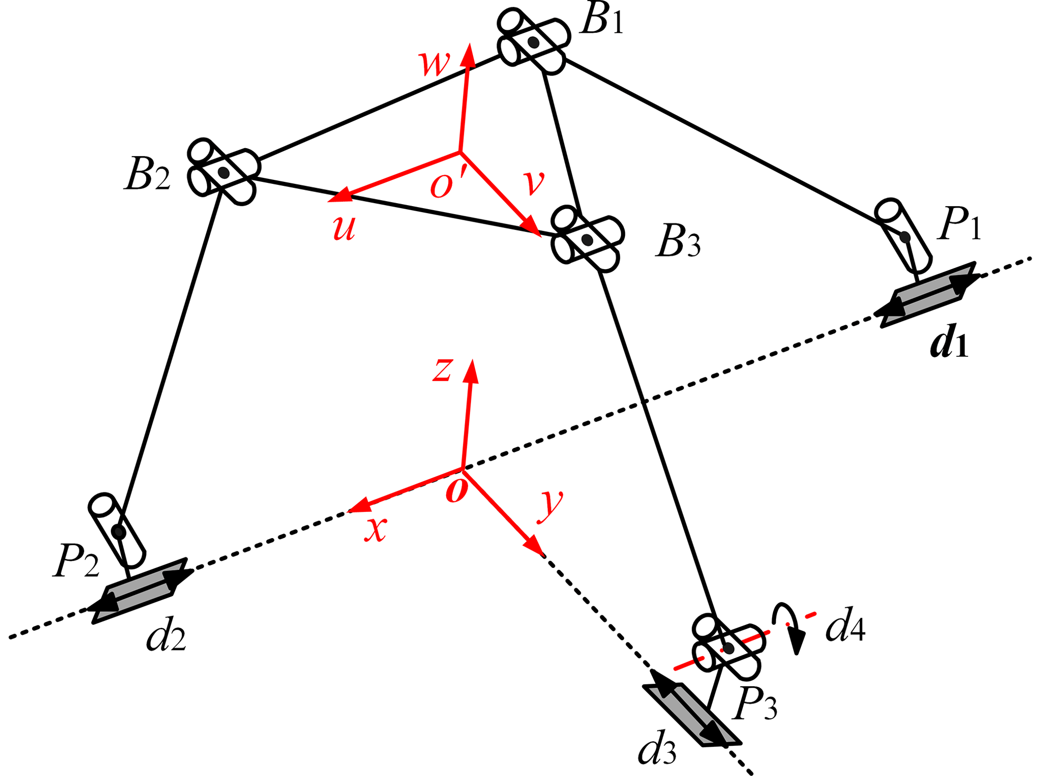
Kinematic and dynamic analyses are built on the inverse position solution of PMs. For the convenience of analysis, the kinematics model of 2PRU-PUU RPM shown in Fig. 2 is drawn according to the mechanism characteristics. The coordinate vector of point Pi (i= 1, 2, 3) in the fixed coordinate frame can be expressed as
In the moving coordinate frame, the coordinate vector of point Bi (i= 1, 2, 3) can be written as
The coordinate vector of point Bi (i= 1, 2, 3) in the fixed coordinate frame can be written as
where R denotes the rotation matrix from the moving coordinate frame to the fixed coordinate frame.
Substituting Eqs. (1) and (2) into Eq. (3), can be obtained as follows:
Using the constraint equation , three equations can be obtained as follows:
where the “±” notation represents two distinct assembly modes for the limbs, which are selected as “+” according to the actual assembly situation of the RPM.
By analyzing the geometric relation of joints in PUU limbs, the equation of input variable d4 can be obtained as follows:
where the “±” notation is the same as the “±” notation of the output parameter x.
Equations (6) and (7) present the inverse position solutions for the proposed RPM. However, the four output parameters (x, z, θ, φ) are not totally independent since the 2PRU-PUU RPM has 3 DOFs in 1R2T and 2R1T operation modes. When it is in 1R2T operation mode, φ is always zero. In the 2R1T operation mode, coordinates x of the point o′ will be changed with rotation around axis y, satisfying the equation
In this paper, the kinematic equation of the mechanism is established from the viewpoint of energy using the Lagrange method, and the kinetic energy, potential energy, and generalized force of the system are analyzed; thus the dynamic equation of the RPM is derived, and the driving force of the mechanism is optimized.
4.1 Velocity analysis
The driving velocity vectors obtained by deriving Eqs. (6) and (7) with respect to the time derivative can be expressed as
where in the 1R2T operation mode, and in the 2R1T operation mode. J1 is the velocity Jacobian matrix of the RPM under the 1R2T operation mode, and J2 is the velocity Jacobian matrix of the RPM under the 2R1T operation mode.
where Δ1=azcθ, Δ2=axsθ, , , , and .
The linear and angular velocity vectors of the moving platform can be expressed by independent generalized coordinates as
where Ki(i= 1, 2, 3) represents the mapping matrix between the moving platform velocity and the independent generalized coordinate velocity under 1R2T operation mode, switch configuration, and 2R1T operation mode, respectively; they can be expressed as
The velocity of universal joint points Bi in a fixed coordinate frame can be expressed by the velocity of the moving platform as
The velocity vector can also be expressed by the velocity of link as
where is the unit direction vector of the link PiBi.
By substituting Eq. (16) into Eq. (17) and multiplying the vector ni, the angular velocity of the link PiBi can be expressed as
After obtaining the angular velocity of the link PiBi, the linear velocity at the center of mass of the link is
4.2 The kinetic energy of system
The kinetic energy of the RPM includes the kinetic energy of the moving platform, link, and driving pair. The kinetic energy of the moving platform can be expressed as
where Ip represents the moment of inertia matrix at the center of mass of the moving platform.
The kinetic energy of three links of the RPM is
where Ili represents the moment of the inertia matrix at the center of mass of the link.
Three sliders of 2PRU-PUU redundant actuated PMs only have translation motion along the coordinate axis, so there is no rotational kinetic energy generated by three sliders. Correspondingly, the fourth actuator has no linear kinetic energy but rotational kinetic energy.
where vdi denotes the linear velocity vectors of the driving slider, and ωd4 denotes the angular velocity vectors of the fourth actuator.
According to Eqs. (20), (21), and (22), the total kinetic energy of the system can be obtained as follows:
4.3 Potential energy of system
The potential energy is related to the choice of coordinate frame. If the origin point o is the zero potential energy point and the elasticity and friction of the components are ignored, the potential energy of the moving platform, link, and driving pair can be expressed as
where g denotes the acceleration of gravity, and zp, zli, and zdi are the position vectors of the centroid of the moving platform, the links, and the driving pairs in the fixed coordinate frame.
The total potential energy of the system can be obtained from Eqs. (24), (25), and (26).
4.4 Dynamic modeling
The dynamic models of the manipulator are now derived via the Lagrangian formulation as
where is the Lagrangian function; T and U are the kinetic energy and potential energy functions of the system, respectively; and τ is the generalized force.
The kinetic energy and potential energy of the system have been obtained in Sect. 4.2 and 4.3. By substituting Eqs. (23) and (27) into Eq. (28), the dynamic equation of 2PRU-PUU RPM can be obtained as follows
where , ,
According to the principle of virtual work (Tsai, 1998), the relation between the generalized force and axial driving force can be expressed as
where is the driving force, and is the force Jacobian matrix of the system.
As we can see, there are three independent equations with four unknown driving forces in Eq. (29). However, J is a non-full-rank matrix, and the unique solution of the driving force cannot be solved directly. To obtain a unique solution, an optimization technique has to be applied. For different demands, different optimizing objectives are needed. In this paper, the optimization problem of the driving force of the weighted least-squares method can be expressed as follows: the optimization variable is the driving moment F, and under the constraint condition τ=JTF, the driving force F of the objective function Z=FTWF is minimized, where W is a diagonal weighted matrix, which represents the weight of the driving force of each limb (Fontes and Da Silva, 2016; Park et al., 2003).
For the above optimization problems, the Lagrange multiplier method can be used, and the Lagrange multiplier λ is introduced to construct a new function Z′:
In order to get the extremum of Z′, the following conditions must be satisfied
From Eq. (34), the driving force F can be expressed as
Taking the weighting matrix W as the unit matrix,
4.5 Verification with physical simulation
It is known that a= 0.09 m, mp= 0.254 kg, 0.238 kg, ml3= 0.393 kg, 0.053 kg, md3= 0.041 kg, and L= 0.33 m. The correctness of the above dynamic models is verified by ADAMS dynamic simulation software. The trajectory equation of 1R2T operation mode is
The trajectory equation of 2R1T operation mode is
where td= 5 denotes the duration of the motion.
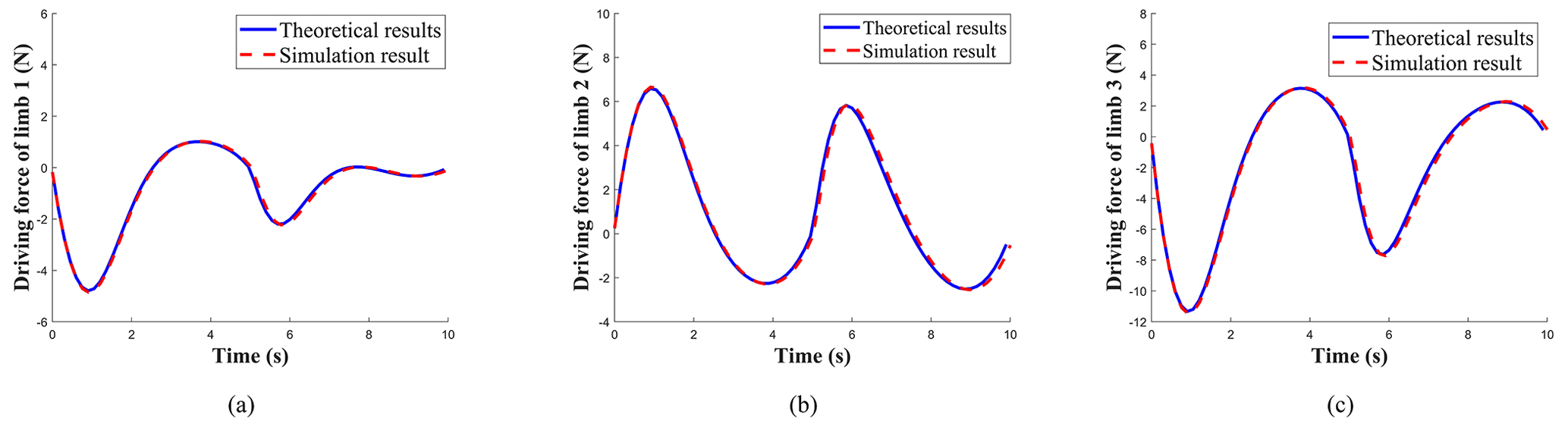
To address the issue that the inverse dynamics solution in the simulation process of redundant actuated PMs is not unique, the displacement of the actuating joints from limb 1 to limb 3 and the theoretical value of the driving 4 are input into ADAMS software, and the unique driving force combination can be obtained.
In Fig. 3, the periods of 1–5 and 5–10 s can be compared relating to the theoretical results and the simulation results of the three limbs' driving force of 1R2T and 2R1T operation mode, respectively. It is evident that the theoretical results and simulation results produce the same computed force outputs, which indicates the correctness of the theoretical analysis, and the dynamic models can be used for the subsequent dynamic performance evaluation.
The dynamic manipulability ellipsoid (DME) index, which is frequently used to investigate the dynamic performance of serial or parallel manipulators, can be used to evaluate the ability of the mechanism to change the position or orientation of the end effector under the constraint of the driving force (Chai et al., 2020). The approximate mapping relation between the generalized acceleration vector and the driving force vector can be obtained by ignoring the velocity factor and the gravity factor. Equation (36) can be rewritten as
where H represents the pose matrix of each component of the mechanism, Φ represents the inertia tensor and mass matrix of each component in the mechanism, is the Jacobian matrix between the moving platform and generalized coordinates, and ap is the acceleration of the moving platform.
According to Eq. (39), an ellipsoid can be obtained to describe the acceleration boundary of the end effector in various directions under the constraint of driving force as follows:
where represents the generalized driving forces, is the inertia matrix of the mechanism, and represents the acceleration of the end effector. is the Jacobian matrix relating the actuated joints of mechanism to its end effector.
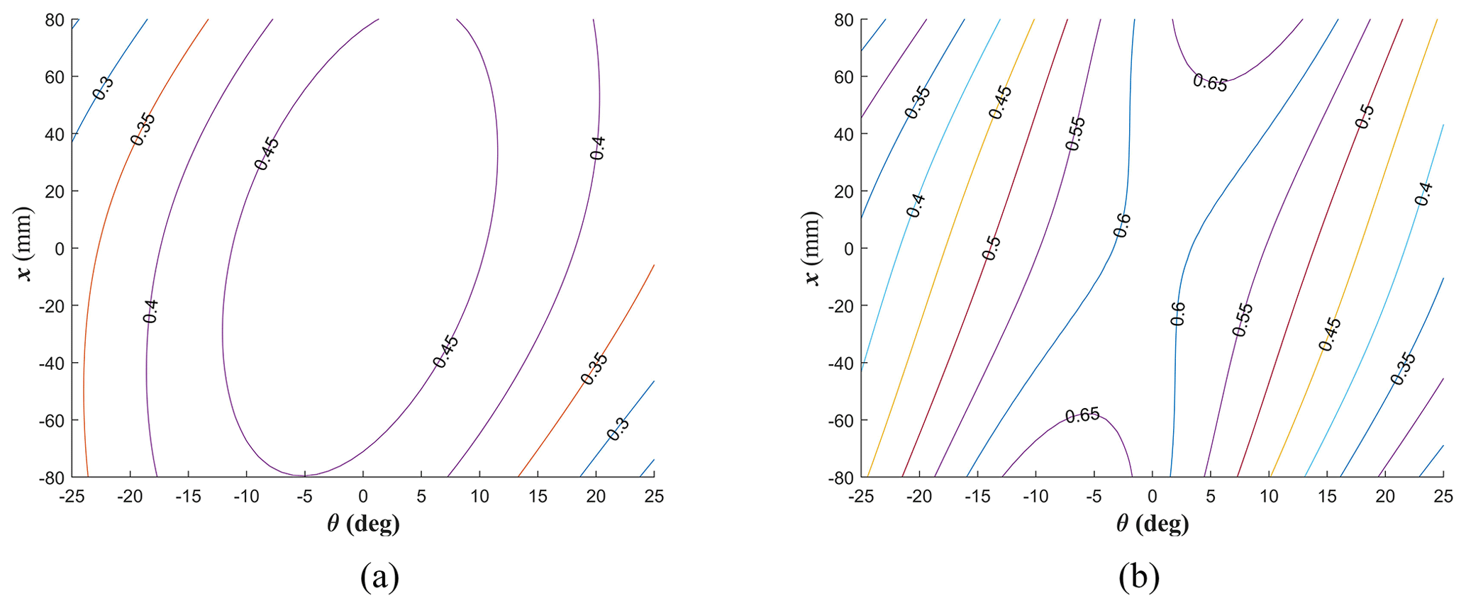
Figure 4Dynamic performance distribution of 1R2T operating mode. (a) Rotational dynamic manipulability index. (b) Translational dynamic manipulability index.
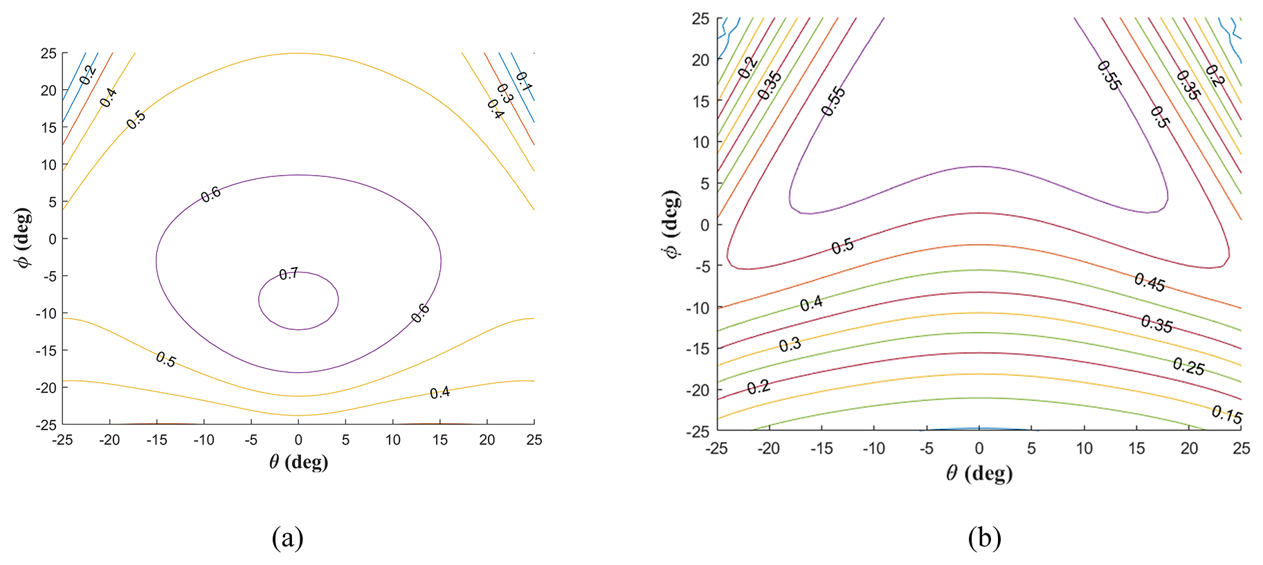
Figure 5Dynamic performance distribution of 2R1T operating mode. (a) Rotational dynamic manipulability index. (b) Translational dynamic manipulability index.
By replacing the corresponding Jacobian matrices with separate Jacobian matrices (Chen et al., 2017), the DME index for rotational and translational of the mechanism can be derived from Eq. (40), which is expressed as
where and correspond to the Jacobian matrix of rotational and translational, respectively.
The isotropic property of rotational dynamic manipulability of the 2PRU-PUU RPM is evaluated by the condition number, which is expressed as
where σR1 and σR2 are nonzero singular values of , and σR1≥σR2.
In the same way, the isotropic property of translational dynamic manipulability is evaluated by the condition number, which is expressed as
where σT1 and σT2 are nonzero singular values , and σT1≥σT2.
According to Eqs. (42) and (43), the performance distribution of dynamic manipulability of rotation and translation of 2PRU-PUU RPM in two operation modes at z= 230 mm can be obtained, as shown in Figs. 4 and 5. In Fig. 4, the rotational and translational dynamic manipulability of 1R2T operation mode is symmetrical with respect to θ= 6.84° because the 2PRU-PUU RPM is symmetrical with respect to θ= 6.84° in the 1R2T operation mode, and the mechanism is symmetrical with respect to θ= 0° when moving to the 2R1T operation mode. As can be seen from Fig. 5, the rotational and translational dynamic manipulability of 2R1T operation mode is symmetrical with respect to θ= 0°, which conforms to the structural characteristics of the 2PRU-PUU RPM. At the isotropic property becomes better because the effect of the differential motion between limb 1 and limb 2 decreases with a more oblique configuration of the end effector.
This paper presents kinematic, dynamic, and performance analysis of a novel 2PRU-PUU RPM. From the switch configuration, the mechanism can evolve into 1R2T operation mode and 2R1T operation mode. The dynamic models of the 2PRU-PUU RPM are established based on the Lagrange method. To solve the problem of the non-uniqueness solution of redundant actuator PMs in dynamic analysis, the weighted least-squares norm is introduced. The results of the modeling method have been validated by means of numerical simulations of commercial ADAMS software. The DME index is then adopted to evaluate the dynamic manipulability performance of the 2PRU-PUU RPM. And the dynamic performance of rotation and translation of the mechanism in the workspace is derived. The overall performance of the two operation modes of the RPM is better at the operating height of z= 0.23 m and . It provides a basis for subsequent performance optimization and prototype motion control. In future work, we will investigate the multi-objective optimization design of the 2PRU-PUU RPM.
The data generated during this study are available from the corresponding author on reasonable request.
Conceptualization: TS and CY. Methodology: WY and FH. Software: TS and CY. Validation: TS and FH. Formal analysis: WY and TS. Investigation: TS and CY. Resources: FH. Writing (original draft preparation): FH and CY. Writing (review and editing): TS and CY. Visualization: WY and TS. Supervision: WY. Project administration: FH. Funding acquisition: WY and FH.
The contact author has declared that none of the authors has any competing interests.
Publisher’s note: Copernicus Publications remains neutral with regard to jurisdictional claims made in the text, published maps, institutional affiliations, or any other geographical representation in this paper. While Copernicus Publications makes every effort to include appropriate place names, the final responsibility lies with the authors.
This research has been supported by the Basic Public Welfare Research Program of Zhejiang Province, China (grant no. LGG20E050021).
This paper was edited by Guowu Wei and reviewed by two anonymous referees.
Abo-Shanab, R. F.: Dynamic modeling of parallel manipulators based on Lagrange–D'Alembert formulation and Jacobian/Hessian matrices, Multibody Syst. Dyn., 48, 403–426, https://doi.org/10.1007/s11044-019-09705-0, 2020.
Arata, J., Kondo, H., Ikedo, N., and Fujimoto, H.: Haptic Device Using a Newly Developed Redundant Parallel Mechanism, IEEE T. Robot., 27, 201–214, https://doi.org/10.1109/TRO.2010.2098272, 2011.
Carbonari, L., Costa, D., Palmieri, G., and Palpacelli, M.-C.: Reconfigurability Analysis of a Class of Parallel Kinematics Machines, J. Mech. Robot., 11, 021002, https://doi.org/10.1115/1.4042348, 2019.
Chai, X., Wang, M., Xu, L., and Ye, W.: Dynamic modeling and analysis of a 2PRU-UPR parallel robot based on screw theory, IEEE Access, 8, 78868–78878, https://doi.org/10.1109/ACCESS.2020.2989783, 2020.
Chen, G., Yu, W., Li, Q., and Wang, H.: Dynamic modeling and performance analysis of the 3-PRRU 1T2R parallel manipulator without parasitic motion, Nonlinear Dynam., 90, 339–353, https://doi.org/10.1007/s11071-017-3665-0, 2017.
Chen, M., Zhang, Q., Qin, X., and Sun, Y.: Kinematic, dynamic, and performance analysis of a new 3-DOF over-constrained parallel mechanism without parasitic motion, Mech. Mach. Theory, 162, 104365, https://doi.org/10.1016/j.mechmachtheory.2021.104365, 2021.
Chen, X., Liu, X. J., Xie, F. G., and Sun, T.: A comparison study on motion/force transmissibility of two typical 3-DOF parallel manipulators: The sprint Z3 and A3 tool heads, Int. J. Adv. Robot. Syst., 11, 1–10, https://doi.org/10.5772/57458, 2014.
Chiacchio, P.: New dynamic manipulability ellipsoid for redundant manipulators, Robotica, 18, 381–387, https://doi.org/10.1017/S0263574799002106, 2000.
Elgolli, H., Houidi, A., Mlika, A., and Romdhane, L.: Analytical analysis of the dynamic of a spherical parallel manipulator, Int. J. Adv. Manuf. Tech., 101, 859–871, https://doi.org/10.1007/s00170-018-2939-0, 2019.
Fontes, J. V. and Da Silva, M. M.: On the dynamic performance of parallel kinematic manipulators with actuation and kinematic redundancies, Mech. Mach. Theory, 103, 148–166, https://doi.org/10.1016/j.mechmachtheory.2016.05.004, 2016.
Gan, D., Dai, J. S., Dias, J., and Seneviratne, L.: Joint force decomposition and variation in unified inverse dynamics analysis of a metamorphic parallel mechanism, Meccanica, 51, 1583–1593, https://doi.org/10.1007/s11012-015-0216-y, 2016.
Hu, B., Yu, J., Lu, Y., Sui, C., and Han, J.: Statics and Stiffness Model of Serial-Parallel Manipulator Formed by k Parallel Manipulators Connected in Series, J. Mech. Robot., 4, 021012, https://doi.org/10.1115/1.4006190, 2012.
Hu, B., Zhao, J., and Cui, H.: Terminal constraint and mobility analysis of serial-parallel manipulators formed by 3-RPS and 3-SPR PMs, Mech. Mach. Theory, 134, 685–703, https://doi.org/10.1016/j.mechmachtheory.2019.01.004, 2019.
Hu, B., Shi, D., Xie, T., Hu, B., and Ye, N.: Kinematically Identical Manipulators Derivation for the 2-RPU + UPR Parallel Manipulator and Their Constraint Performance Comparison, J. Mech. Robot., 12, 061011, https://doi.org/10.1115/1.4047540, 2020a.
Hu, B., Shi, Y., Xu, L., and Bai, P.: Reconsideration of terminal constraint/mobility and kinematics of 5-DOF hybrid manipulators formed by one 2R1T PM and one RR SM, Mech. Mach. Theory, 149, 103837, https://doi.org/10.1016/j.mechmachtheory.2020.103837, 2020b.
Kalani, H., Rezaei, A., and Akbarzadeh, A.: Improved general solution for the dynamic modeling of Gough–Stewart platform based on principle of virtual work, Nonlinear Dynam., 83, 2393–2418, https://doi.org/10.1007/s11071-015-2489-z, 2016.
Karimi Eskandary, P. and Angeles, J.: The dynamics of a parallel Schönflies-motion generator, Mech. Mach. Theory, 119, 119–129, https://doi.org/10.1016/j.mechmachtheory.2017.09.006, 2018.
Kong, X.: Type synthesis of 3-DOF parallel manipulators with both a planar operation mode and a spatial translational operation mode, J. Mech. Robot., 5, 041015, https://doi.org/10.1115/1.4025219, 2013.
Kong, X.: Reconfiguration analysis of a 3-DOF parallel mechanism using Euler parameter quaternions and algebraic geometry method, Mech. Mach. Theory, 74, 188–201, https://doi.org/10.1016/j.mechmachtheory.2013.12.010, 2014.
Kureková, E. and Halaj, M.: Theoretical aspects of control of the Tricept type parallel kinematic structure, 393–397, https://doi.org/10.1109/CarpathianCC.2014.6843634, 2014.
Li, Q. and Herve, J. M.: Short Papers of Schoenflies Motion, IEEE T. Robot., 25, 158–164, 2009.
Li, T., Jia, S., and Wu, J.: Dynamic model of a 3-DOF redundantly actuated parallel manipulator, Int. J. Adv. Robot. Syst., 13, 1729881416662791, https://doi.org/10.1177/1729881416662791, 2016.
Liu, W. and Liu, H.: Synthesis of asymmetric parallel mechanism with multiple 3-DOF motion modes, Adv. Mech. Eng., 14, 16878140221075308, https://doi.org/10.1177/16878140221075309, 2022.
Park, D. I., Lee, S. H., Kim, S. H., and Kwak, Y. K.: Torque distribution using a weighted pseudoinverse in a redundantly actuated mechanism, Adv. Robotics, 17, 807–820, https://doi.org/10.1163/156855303322395226, 2003.
Pedrammehr, S., Nahavandi, S., and Abdi, H.: Closed-form dynamics of a hexarot parallel manipulator by means of the principle of virtual work, Acta Mech. Sinica, 34, 883–895, https://doi.org/10.1007/s10409-018-0761-4, 2018.
Tsai, L.-W.: Solving the Inverse Dynamics of Parallel Manipulators by the Principle of Virtual Work, in: International Design Engineering Technical Conferences and Computers and Information in Engineering Conference, Atlanta, Georgia, USA 13–16 September 1998, American Society of Mechanical Engineers, V01BT01A051, https://doi.org/10.1115/DETC98/MECH-5865, 1998.
Wang, Y., Belzile, B., Angeles, J., and Li, Q.: The Modeling of Redundantly Actuated Mechanical Systems, J. Mech. Robot., 11, 1–20, 2019.
Yang, C., Ye, W., and Li, Q.: Review of the performance optimization of parallel manipulators, Mech. Mach. Theory, 170, 104725, https://doi.org/10.1016/j.mechmachtheory.2022.104725, 2022.
Ye, W., Fang, Y., and Guo, S.: Reconfigurable parallel mechanisms with planar five-bar metamorphic linkages, Sci. China Technol. Sc., 57, 210–218, https://doi.org/10.1007/s11431-013-5433-9, 2014.
Ye, W., Hu, L., and Li, Q.: Kinematic Analysis and Dimension Optimization of a New Reconfigurable Parallel Mechanism With 1R2T and 2R1T Operation Modes, J. Mech. Robot., 14, 060914, https://doi.org/10.1115/1.4055327, 2022.
Yoshikawa, T.: Translational and Rotational Manipulability of Robotic Manipulators, in: 1990 American control conference, San Diego, CA, USA, 23–25 May 1990, IEEE, 228–233, 1990.
Zhao, Y., Gao, F., Li, W., Liu, W., and Zhao, X.: Development of 6-dof parallel seismic simulator with novel redundant actuation, Mechatronics, 19, 422–427, https://doi.org/10.1016/j.mechatronics.2008.11.013, 2009.