the Creative Commons Attribution 4.0 License.
the Creative Commons Attribution 4.0 License.
 | 22 Mar 2024
Modeling and control system experiment of a novel series three-axis stable platform
Da Song
Ji Ma
Lixun Zhang
In this paper, a novel series three-axis stable platform (STSP) is proposed, and its azimuth angle structure, pitch angle structure, roll angle structure, overall system structure scheme, and control scheme are designed. The platform is a universal one. The forward and inverse kinematics and dynamics models of the STSP pitch-and-roll mechanisms are established, and the motion rules of the platform and the force conditions of the main components are analyzed. Establish a mathematical model of the platform control system, analyze the performance of the pitch-and-roll system of the STSP, propose a position velocity dual-closed-loop control strategy, and determine the controller parameters through simulation analysis of the control system. A comprehensive experiment is carried out to install the STSP on the swing platform; simulate the actual operating environment, verify the rationality and dynamic accuracy of the kinematic model, dynamic model, and control strategy; and verify the feasibility and stability of the system control scheme and platform configuration.
- Article
(8480 KB) - Full-text XML
- BibTeX
- EndNote


The main function of the stable platform is to isolate the impact of the installation carrier movement or external interference, provide a stable working environment for the equipment installed on the stable platform by establishing a stable reference plane, prevent the target loss or positioning error caused by the installation carrier movement, and achieve accurate tracking and positioning (Huang et al., 2021; Kuseyri, 2016; Soltani et al., 2011; Li, et al., 2018). It is this function based on the stable platform that makes it play a very important role in human–robot interaction, industry, rehabilitation, and other fields (Dasgupta and Mruthyunjaya, 2000; Yang et al., 2022; Chen et al., 2016; Yu, et al., 2019; Hilkert, 2008). In recent years, with the increase in its demand, research and investment in the stable platform in various countries have increased year by year.
Generally, there are two types of stabilized platform mechanisms: a serial mechanism and a parallel mechanism. The tandem mechanism is mainly composed of two or more basic mechanisms, which are combined in series to enable the follower to achieve a specific motion law (Königseder et al., 2016; Bras et al., 2011; Guo and Dan, 2015). The combination form of the parallel mechanism is different from that of the series mechanism. It combines the basic mechanisms in parallel and drives the follower movement to complete a specific motion path (Jaime and Alcaraz, 2018; Slavutin and Reich, 2020; Slavutin et al., 2019; Song, et al., 2014). The advantages of a parallel structure are a high stiffness and strong bearing capacity, while the disadvantages are a complex structure, large volume, and limited range of motion. Generally, parallel mechanisms are often used in high-speed and large bearing capacity situations (Tian and Zhang, 2020; Wang et al., 2017; Tian et al., 2018; Zhang, et al., 2021). The advantages of a serial mechanism are the simple structure, low processing cost, simple control, large movement space, etc. (Wang et al., 2022; Jun and Feng, 2020).
In the process of modeling and controller design of a servo drive system based on a transfer function, the common design method is classical control theory (Liu et al., 2021). This method has mature technology and high precision and is mainly applicable to linear time-invariant single-input–single-output systems. Due to the structure, control strategy, and other reasons, the existing stable platform has a large volume of equipment and a relatively low control accuracy, which finds it increasingly difficult to meet the use requirements. Based on this situation, this paper designs a novel series three-axis stable platform, which has a higher control accuracy and stability and reduces the overall equipment volume and weight. This platform is a universal platform that can be used for vehicle- or ship-mounted aiming and tracking devices as well as for ankle rehabilitation training.
2.1 Overall organization scheme design
The STSP proposed in this paper has a small load and compact overall space. If the parallel mechanism is adopted, the overall structure weight will be increased. In addition, the weight of the load itself is small, which can be integrated with a degree of freedom to a certain extent to reduce the overall volume. Therefore, considering the design, control, cost, and other factors, a series structure is adopted. The overall mechanism diagram is shown in Fig. 1.
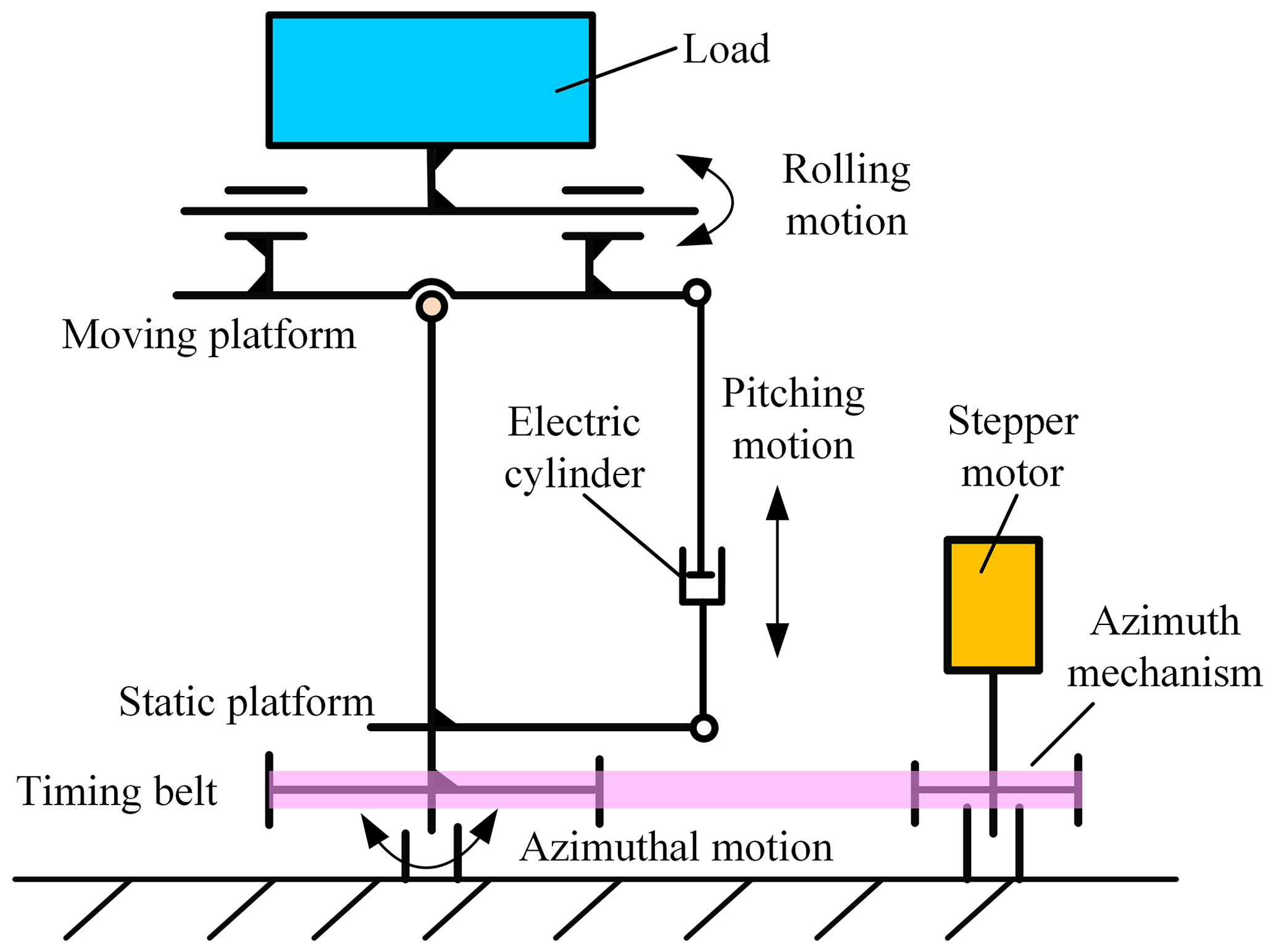
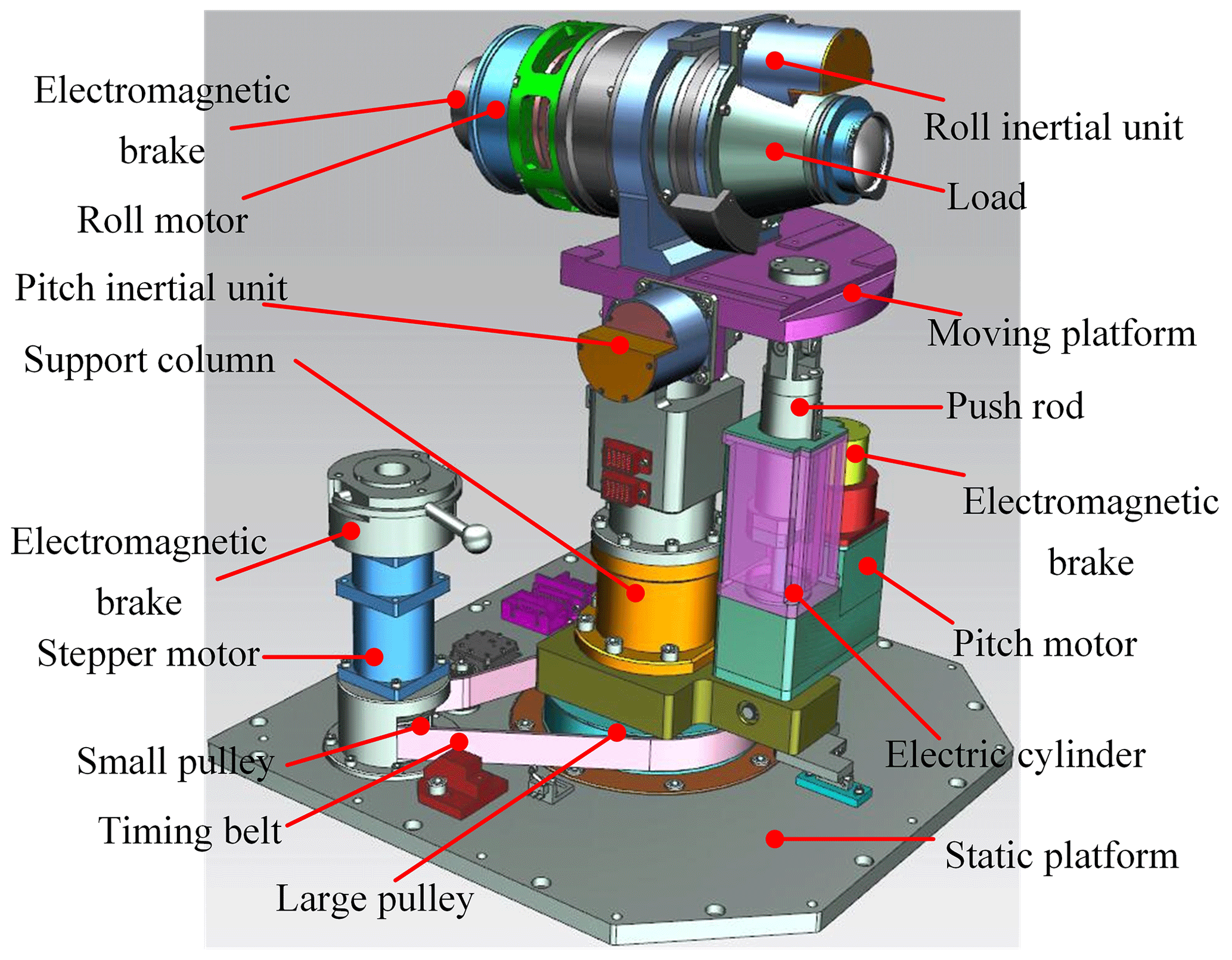
There are three directions of motion for the STSP. From bottom to top, they are azimuth motion, pitch motion, and roll motion. The roll direction movement and the load are integrated, which simplifies the structure design. The pitch mechanism is connected by the designed electric cylinder with the hinge at the bottom of the column and the hinge at the end of the moving platform. This structure increases the transmission ratio and improves the load capacity of the platform. The azimuth rotation is mainly driven by the stepper motor through the pulley to rotate the column as a whole, so that the load points to different orientations. The three-dimensional model of its overall structure is shown in Fig. 2.
2.1.1 Azimuth structure
In Fig. 2, a large belt pulley is installed at the bottom of the middle column of the stabilization platform. The large belt pulley is connected to a small belt pulley in the adjacent azimuth drive mechanism through the synchronous belt, which makes the support column rotate along the central axis and makes the pitch mechanism, roll mechanism, and load move.
2.1.2 Pitch angle structure
The load is located on the moving platform of the STSP. In order to improve the load capacity, the pitch angle movement is provided by the electric cylinder mechanism. The electric cylinder mechanism is mainly composed of a detection device, a driving mechanism, a ball screw mechanism, a guide mechanism, and a gear. The upper end of the push rod is connected to the moving platform through a hinge, and the lower end is connected to the connection point on the side of the support column through a hinge. The moving platform is driven by the telescopic movement of the push rod to achieve pitch angle movement. The pitch inertial unit (sensor) located on the moving platform is used to detect the pitch angle change of the moving plane. The resolver is used to detect the angle of the motor. When the motor is stopped or needs to be fixed to a certain position, the electromagnetic brake can lock the motor to keep the moving platform stable.
2.1.3 Roll angle structure
Considering the limitation of the size of the load mechanism and the overall space size, the direct drive mode is adopted to combine the rolling drive mechanism and the load and to fix them on the moving platform through the bracket in the middle. This design method simplifies the structural design and saves space by directly connecting the motor at its tail. The front end of the motor is installed with a rotary transformer, and the end is installed with an electromagnetic brake. The roll inertial unit (sensor) is installed above the load, which moves with the load to detect the change in the roll angle.
2.2 System overall control scheme design
The STSP has many functions and is decentralized. The motor servo control system and various detection systems have strong independence, and the relationship between each loop is complex. Therefore, based on comprehensive consideration, the distributed control mode is adopted. The overall control scheme of the STSP is shown in Fig. 3.
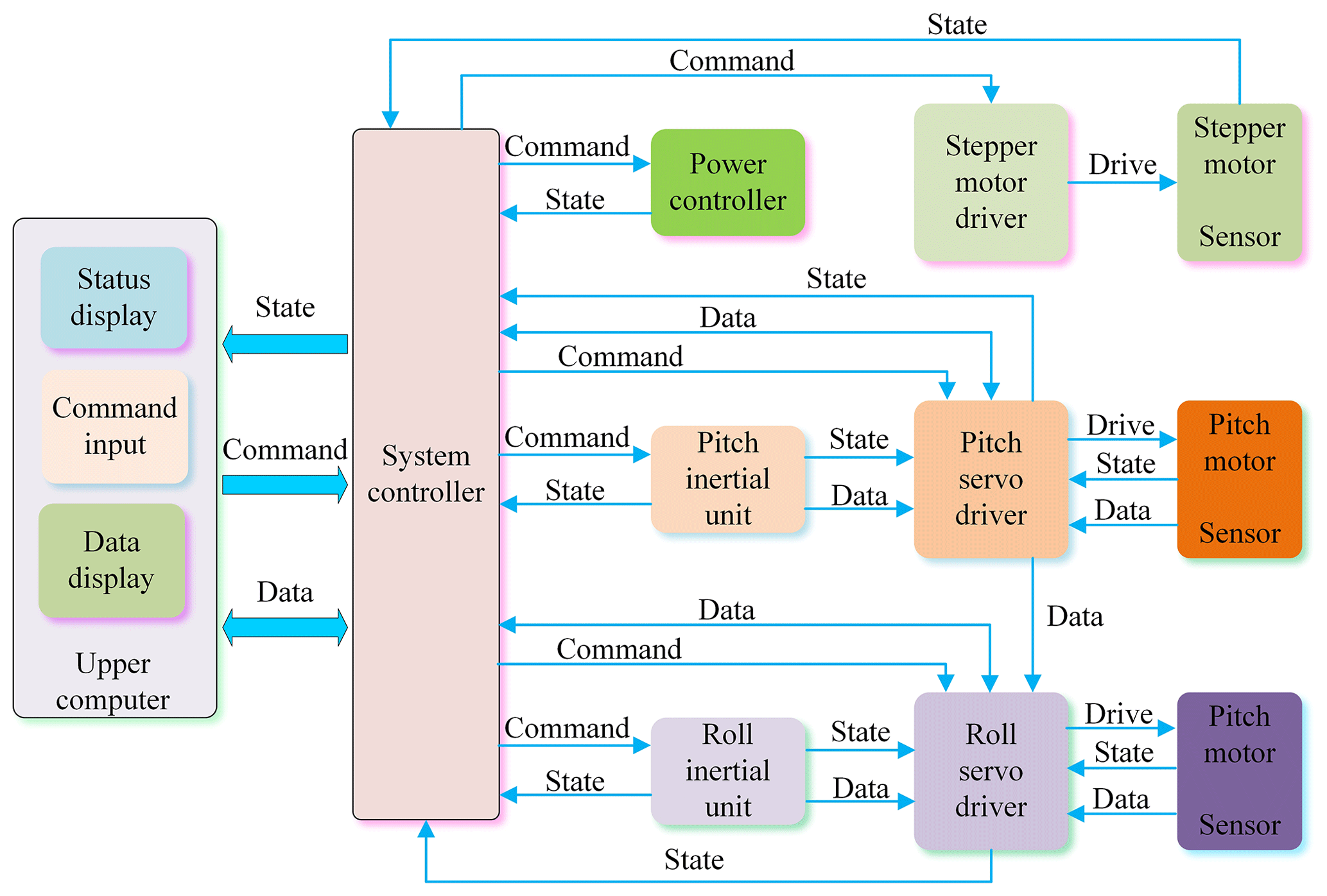
The STSP adopts distributed control. Each servo driver, inertial unit, and power manager is independent of the other and is responsible for its respective tasks. The system controller, as a transit station, is responsible for transmitting the information for each submodule of the lower computer and the upper computer. There are mainly three kinds of information transmitted between the modules of the control system, i.e., status information, data information, and command information. The status information mainly refers to the lower computer submodule reflecting the working status information of the module to the upper computer, such as current information, temperature information, or limit alarm information. The data information mainly refers to the data transmission between the upper computer and the lower computer submodules and between the lower computer submodules, such as roll angle, elevation angle, or pitch angle error. The command information mainly refers to the working mode commands sent by the upper computer to each module of the lower computer, including initialization instructions, startup commands, or elevation setting commands.
The relationship between each information and data flow can be distinguished by Fig. 3. The upper computer sends commands to all the submodules through the system controller to check the status information of each module. In addition, the inertial unit module, servo driver module, and motor module constitute an independent servo drive module. The inertial unit and motor end sensor transmit measurement data to the motor driver and control the motor movement after calculation and processing by the servo driver, thus completing the control of the platform. The servo drive control is the most important part of the whole system.
3.1 Kinematic modeling and analysis
The forward kinematics of the platform mainly calculate the rotation angle of the motor from the rotation angle of the moving platform, while the inverse kinematics calculate the rotation angle of the moving platform from the rotation angle of the motor. In addition to analyzing the motion law, the transfer function from the platform end to the motor end can be obtained through forward kinematics calculation. In addition, the actual rotation angle of the moving platform can be obtained by inverse kinematics calculation using the motor rotation angle.
3.1.1 Kinematics analysis of the pitch mechanism
In order to reduce the difficulty of modeling the kinematics model, the simplified mechanism motion diagram of the STSP shown in Fig. 2 is also shown in Fig. 4. The pitch mechanism diagram of the STSP is shown in Fig. 4a. The closed-loop vector method is used for kinematics modeling of the pitch mechanism.
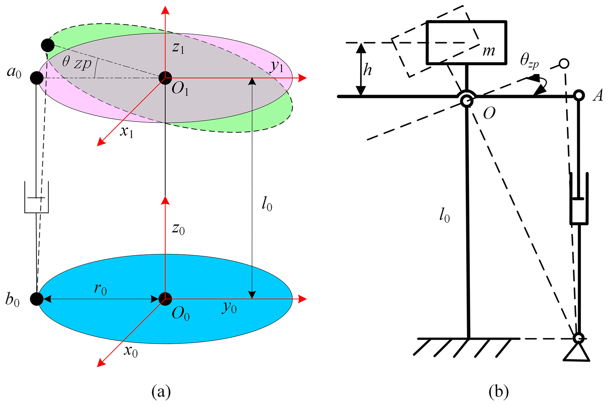
If the moving coordinate system O1-x1y1z1 is established on the moving platform and the static coordinate system O0-x0y0z0 is established on the static platform, then the relevant parameters of the pitch motion at the moving platform end are
where θzp is the platform end pitch angle, nzp is the platform end pitch speed, εzp is the platform end pitch angle acceleration, Az is the platform end pitch angle amplitude, Tz is the platform end pitch period, and .
If the static coordinate system is the reference coordinate system, then any vector H1 in the dynamic coordinate system can be transformed into the static coordinate system through the rotation matrix as
where R is the rotation matrix, , and P is the position vector from the origin of the moving coordinate system to the origin of the static coordinate system .
According to the closed-loop vector method, the kinematics equation of the electric cylinder is established as
where is the position vector from the origin O0 of the static coordinate system to the upper fulcrum a0 of the electric cylinder, is the position vector from the origin O1 of the moving coordinate system to the upper fulcrum a0 of the electric cylinder, is the position vector from the origin O0 of the static coordinate system to the upper fulcrum b0 of the electric cylinder, and L1 is the length vector of the electric cylinder.
(a) Inverse kinematics
Given the space position and attitude of the moving platform, the elongation of the electric push rod is calculated. Among them, , , , and . According to Eq. (3),
where l0 = 265.5 mm is the length from the origin O0 of the moving coordinate system to the origin O1 of the static coordinate system, and r0 = 100 mm is the length from the origin O0 of the moving coordinate system to the lower fulcrum b0 of the electric cylinder.
Let be the position vector at the initial time of the upper and lower fulcrums of the electric cylinder. The position change vector L2 of the electric cylinder is
Calculate the total length of the electric push rod as
The elongation of the electric push rod is
The pitch motor angle is
where p is the lead of the lead screw, and ism is the transmission ratio from the lead screw to the motor end.
The components of L2 in the y0O0z0 plane are
The speed corresponding to the two directions is
The relevant parameters of the electric push rod are
where vl is the linear speed of the push rod and nl is the speed of the lead screw.
The relevant parameters of the pitch motor terminal are
where nzm is the pitch motor speed, and εzm is the pitch motor angular acceleration.
(b) Forward kinematics
Calculate the angle of the platform end from the angle of the motor end, where the extension of the push rod is
is the equation about θzp, and l1 is the module of vector L1:
Simplified,
Order is then
Simplified,
Then,
3.1.2 Kinematics analysis of the roll mechanism
The rolling motion of the load is directly driven by the rolling motor through the coupling. Therefore, the rolling angle motion parameters are the same as those of the rolling motor.
θhp is the platform end rolling angle, θhm is the rolling motor end angle, nhp is the rolling speed at the platform end, nhm is the rolling motor speed, εhp is the platform end roll angular acceleration, εhm is the roll motor end angular acceleration, Ah is the amplitude of the platform end roll angle, Th is the rolling period of the platform end, and .
3.1.3 Kinematics analysis
The kinematics model of the roll mechanism and the pitch mechanism are established by using MATLAB to solve the motion law of the moving platform of the STSP, verify the correctness of the forward and inverse kinematics formulas, and analyze the relationship between the elongation of the electric push rod and the rotation angle of the moving platform. The inverse kinematics equations of the platform are established by Eqs. (1), (7), (8), and (19), and the forward kinematics equations of the platform are established by Eqs. (13), (18), and (19). Set r0 = 100 mm and l0 = 265.5 mm to get the rolling and pitching motion relationships of the moving platform.
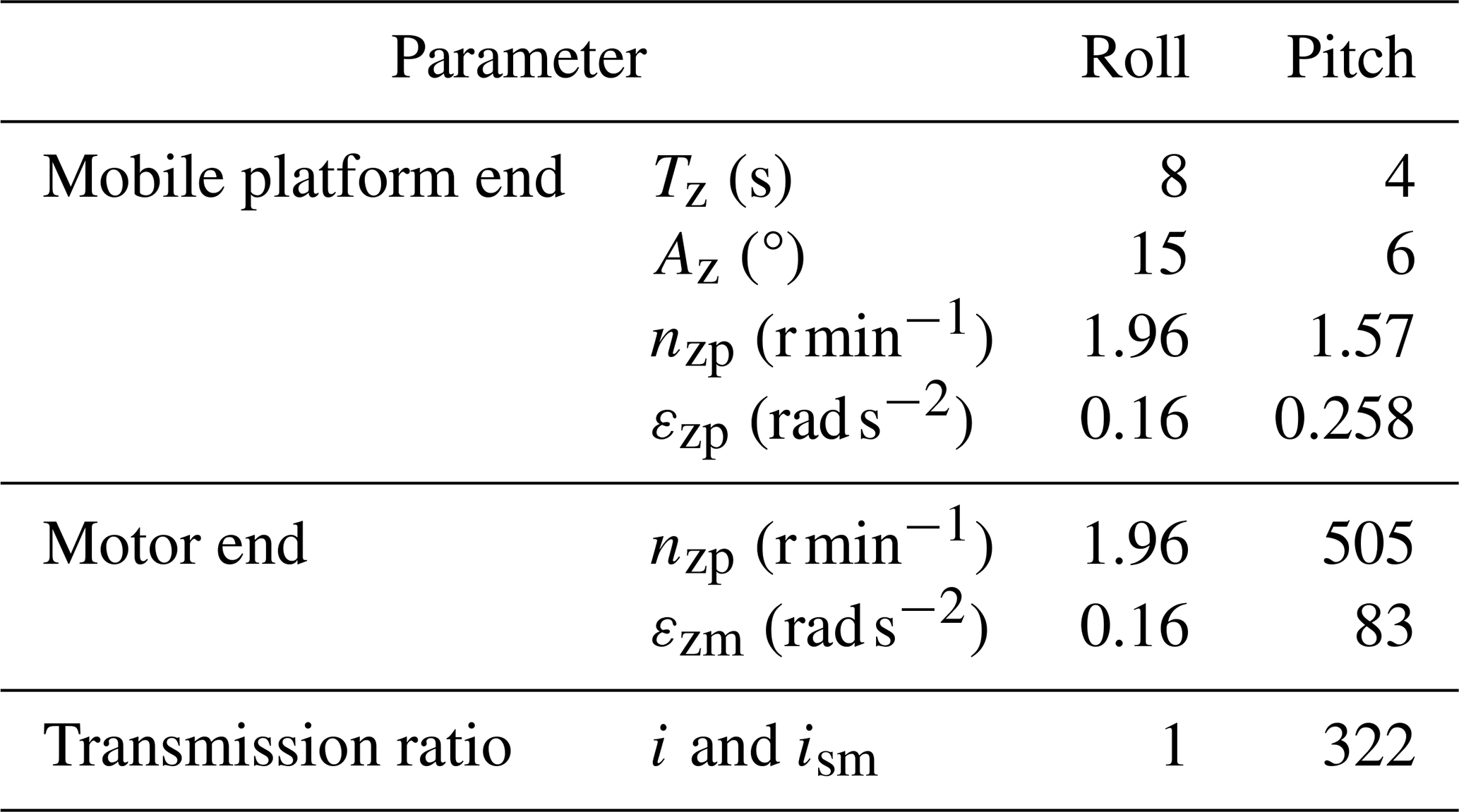
According to the above analysis, the relevant parameters of the STSP are shown in Table 1.
3.2 Dynamic modeling and analysis
Dynamic analysis mainly analyzes the force of the mechanism, calculates the moment of inertia and force of the mechanism, calculates the torque and speed of the motor terminal, and analyzes the mechanical characteristics of the motor. In addition, the results of the dynamics calculation are applied to control system modeling and system performance analysis.
3.2.1 Force analysis of the pitch mechanism
The load of the pitch mechanism is mainly composed of the gravity load, the friction load, and the inertia load of the load. The mechanism diagram during its movement is shown in Fig. 4b. The gravity is a load and roll mechanism. When the electric push rod retracts, the moving platform rotates clockwise, and the push rod is under pressure. When the electric push rod extends, the moving platform rotates counterclockwise, and when it rotates over a certain angle, the push rod is under tension. Therefore, at the position of the two limits, the force on the push rod is largest.
If the STSP inertia moment is Tzp and the weight moment is Tzg, then
where Jzp = 0.301 kg m2 is the moment of inertia of the pitch load, m = 8.7 kg is the mass of the load and rolling mechanism, and h = 76.7 mm is the vertical distance between the load center of the mass and the upper surface of the moving platform.
With the horizontal position of the moving platform as the benchmark and the upward thrust of the push rod as the positive direction, the force of the moving platform for a period is analyzed. When the moving platform moves counterclockwise from the lower-limit position, the gravity load, inertia load, and friction load simultaneously do negative work. However, when moving over the horizontal position, the gravity load and inertia load do negative work, and the friction load does positive work. When moving clockwise from the upper-limit position, the gravity load and inertia load do negative work, and the friction load does negative work. After passing the horizontal position, the gravity load and inertia load do negative work, and the friction load does positive work. Therefore, according to the different motion angles of the moving platform, the direction of work done by the friction force is different, and the functional equation needs to be established in sections as
where Fs is the point-A thrust of the electric push rod, and Tzf = −0.2 N m is the friction torque.
The force balance equation is
where Gt = 6 N is the weight of the push rod sleeve, and Ft is the total thrust of the push rod.
The driving torque Tzs of the lead screw is
where ηzs = 0.8 is the transmission efficiency of the push rod lead screw.
3.2.2 Force analysis of the roll motor
The roll motor is directly connected to the load through the coupling, and the load it receives mainly includes the friction load and the inertia load. The shape of the load is approximate to a cylinder. The inertial moment of the load and inertial unit is Tgx, and the rotating friction load is Tgf. Take the product of the maximum inertial moment Tgxmax and the friction coefficient; then,
where mg = 4 kg is the mass of the load and the rolling inertial unit, rg = 0.071 m is the radius of the load, Jgx is the rotational inertia of the load and rolling inertia unit, and khf = 0.1 is the friction coefficient of the roll mechanism.
Then, the total driving torque Thm of the roll motor is
where ηh = 0.8 is the transmission efficiency of the roll mechanism.
3.2.3 Force analysis of the stepping motor
If the STSP needs to rotate from 0 to 90°, its average angular velocity is wfw = 9 ° s−1. If it takes 0.4 s for the azimuth angle to reach 9 ° s−1 from the static state, its angular acceleration is εfw = 0.393 rad s−1. The platform volume is approximate to a cylinder, and its radius is rfw. Then, the rotary inertia Jfw of the turntable is
where mfw = 50 kg is the overall mass of the platform, and rfw = 0.18 m is the platform radius.
The inertia moment Tfw1 of the platform is
The driving torque Tfw of the platform is
where Tfwf = 18 N m is the integral friction moment of the platform.
The output torque A of the stepping motor is
where ηfw = 0.9 is the transmission efficiency of the conveyor belt, and ifw = 394 is the transmission ratio of the conveyor belt.
When the average angular velocity is wfw = 9 ° s−1, the corresponding motor speed is nb1 = 600 r min−1, and the output torque of the azimuth angle is Tb1 = 0.4 N m. When the maximum speed of the motor is nbmax = 2000 r min−1, the output torque is Tbmax = 0.07 N m.
4.1 Mathematical model of the control object
The DC motor servo system is adopted. The rotor of the DC motor generates a driving force under the action of the armature current and then transfers it to the load through the transmission mechanism to drive the load to produce movement. In this paper, the mathematical models of the roll motion system and the pitch motion system are established.
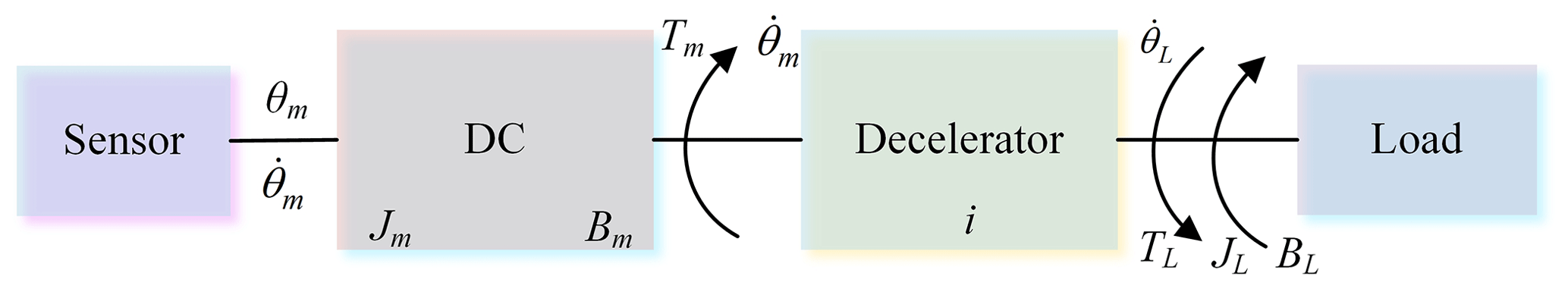
The pitch mechanism and roll mechanism DC motor servo system can actually be simplified as an inertial friction load system, as shown in Fig. 5. The influence of transmission system stiffness is ignored in the motor model.
The voltage equation of the armature circuit is
where Ra is the motor armature circuit resistance, La is the armature inductance, ua is the armature voltage, ia is the armature current, e is the back electromotive force (EMF) of the DC motor, Ce is the back EMF constant, and is the motor speed.
The driving torque of the motor is
where Cm is the torque constant of the DC motor.
The force balance equation of the motor is
where TL is the load torque, is the angular acceleration of the motor, Jm is the load moment of inertia, and Bm is the viscous friction coefficient.
The mathematical model of the electric circuit of the motor after the Laplace transformation of Eq. (30) is
After the Laplace transformations of Eqs. (31)–(33) are combined, the transfer function between the control current and the output speed of the motor is
where i is the transmission ratio of the system, , .
The speed transfer function at the load end is
4.2 Controller design and analysis of the roll system
4.2.1 Design and analysis of the speed loop
The open-loop transfer function of the DC speed servo system is a zero-type system. Therefore, in order to improve the steady-state accuracy of the system and to ensure that the system has good rapidity, the speed loop control loop usually uses a PI controller. The controller is
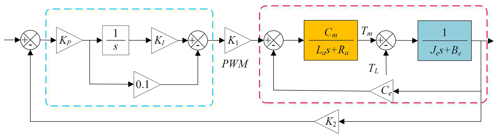
The PI controller has a gain of KPKI, a turning frequency of ω=KI, and a time constant of . Its speed loop control model is shown in Fig. 6.
Set KI = 30, 50, and 70 and KP = 70, and observe the open-loop Bode diagram of the speed loop. With the increase in KP, the crossing frequency gradually increases, and increasing the integral coefficient KI will reduce the phase margin of the system, thus making the stability of the system worse. The overshoot of the closed-loop step response of the system increases with the increase in KI. Increasing the integral coefficient does not improve the rapidity of the system. Therefore, based on comprehensive consideration, KI = 50 and KP = 70 are selected. At this time, the system crosses around −20 dB, and the phase margin is 66°, which is ideal.
4.2.2 Design and analysis of the position velocity double closed loop
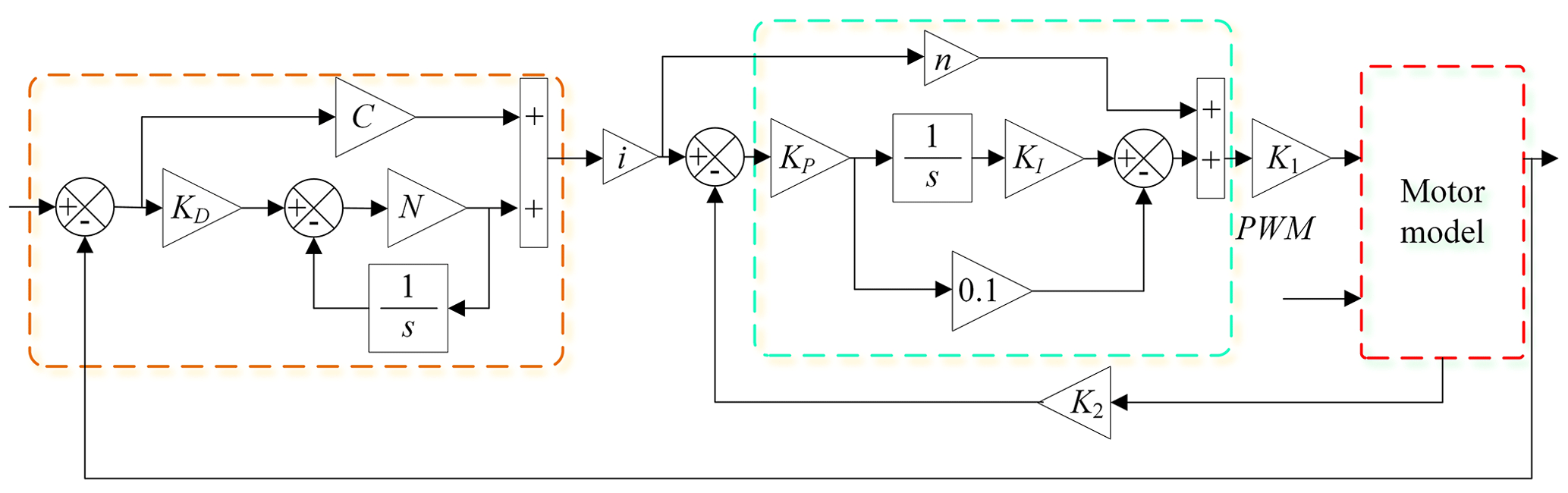
The double closed-loop control model of the designed roll system is shown in Fig. 7.
Increasing the gain makes the crossing frequency increase, and the response speed of the system increases, but the phase margin and amplitude margin also decrease. At C = 230, the phase margin is 75.9°, and at C = 330, the phase margin is 68°. At C = 330, the system response speed increases, but there is a small vibration. After adding a differential, the system performance improves. The system crossing points are all near −20 bB and the bandwidth is large, so the system is relatively stable. The gain of the position loop can be further improved, but considering the discretization required in practical application, the proportion coefficients of the position loop are finally determined as C = 230, KD = 0.1, and N = 400.
4.3 Controller design and analysis of the pitch system
The pitch system model is similar to the roll system, and the PI controller is used in the speed loop design. Through comprehensive comparison and analysis, it is determined that the speed loop controller is KP = 0.4, KI = 80. The position loop controller parameters of the pitch system are C = 315, KD = 0.04, and N = 300. The compound control method is used to compensate for the speed loop to improve the system performance. At this time, the error size is , the error curve is smooth, and the system is relatively stable, meeting the design requirements. The load is introduced into the pitch system in the same form as the roll system, and the error curve changes are observed.
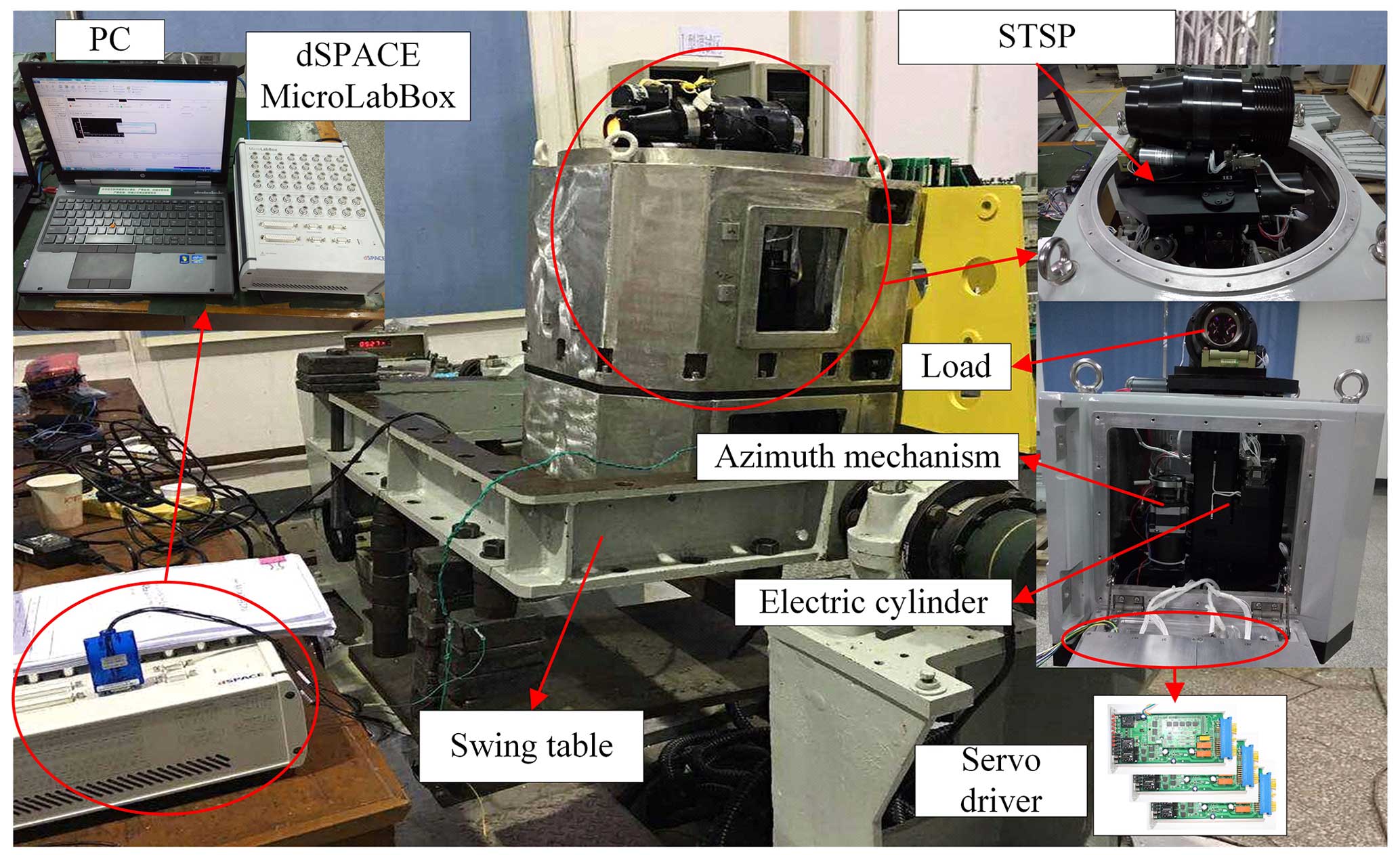
5.1 Experimental environment
The main equipment required for the experiment comprises a dSPACE industrial personal computer, a PC, a servo driver, and a series stabilization platform, as shown in Fig. 8.
5.2 Control system
The workflow of the control system is shown in Fig. 9. After power-on, wait for the initialization instruction. When the initialization task is completed, if the initialization fails, wait here. If the initialization succeeds, wait for the startup instruction. After receiving the startup command, the system first enters the reset program. After the reset, the startup is successful, and the system directly enters the normal working mode. Otherwise, the startup fails, and the motor is turned off. The main tasks of the system under normal working conditions are as follows.
-
Check whether the various states are normal. If there is any abnormality, report it actively. In the case of failure, stop the machine immediately and turn off the motor to enable it.
-
Run the control algorithm program, control the motor to work normally, and calculate the relevant angle, error, and other data.
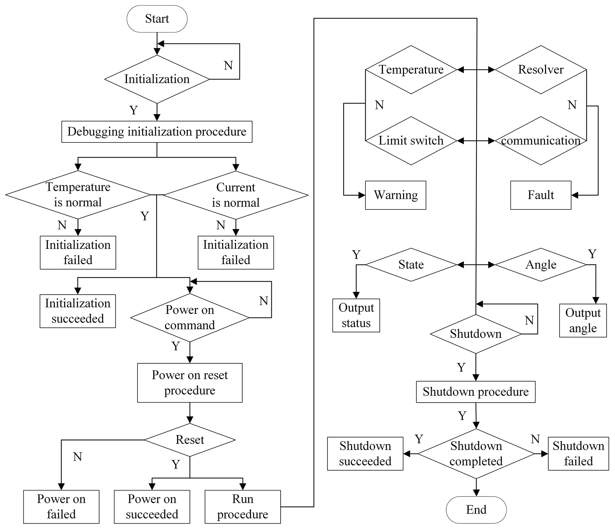
When the system receives the shutdown command, it enters the shutdown program, cuts off the external angle input, automatically resets to the mechanical zero point, and turns off the motor. In order to ensure the smooth and stable operation of the system, the servo driver has strict sequence requirements when working; i.e., the system can only accept the shutdown command after startup but cannot accept the initialization command. When the system is powered on for the first time, it can only accept the initialization command first.
5.3 System comprehensive experiment
The swing table can produce sinusoidal motions with different amplitudes and periods. During installation, the rolling motion of the platform will be perpendicular to the axial direction of the swing table, so as to simulate the rolling motion of the installation carrier. The difference between the comprehensive experiment and the single degree of freedom experiment is that it is a zero input, which depends on the inertial unit to detect the angle change in the platform and is adjusted by the servo system. The system starts to work. Under static conditions, the steady-state errors of the platform in the rolling and pitching directions are shown in Fig. 10.
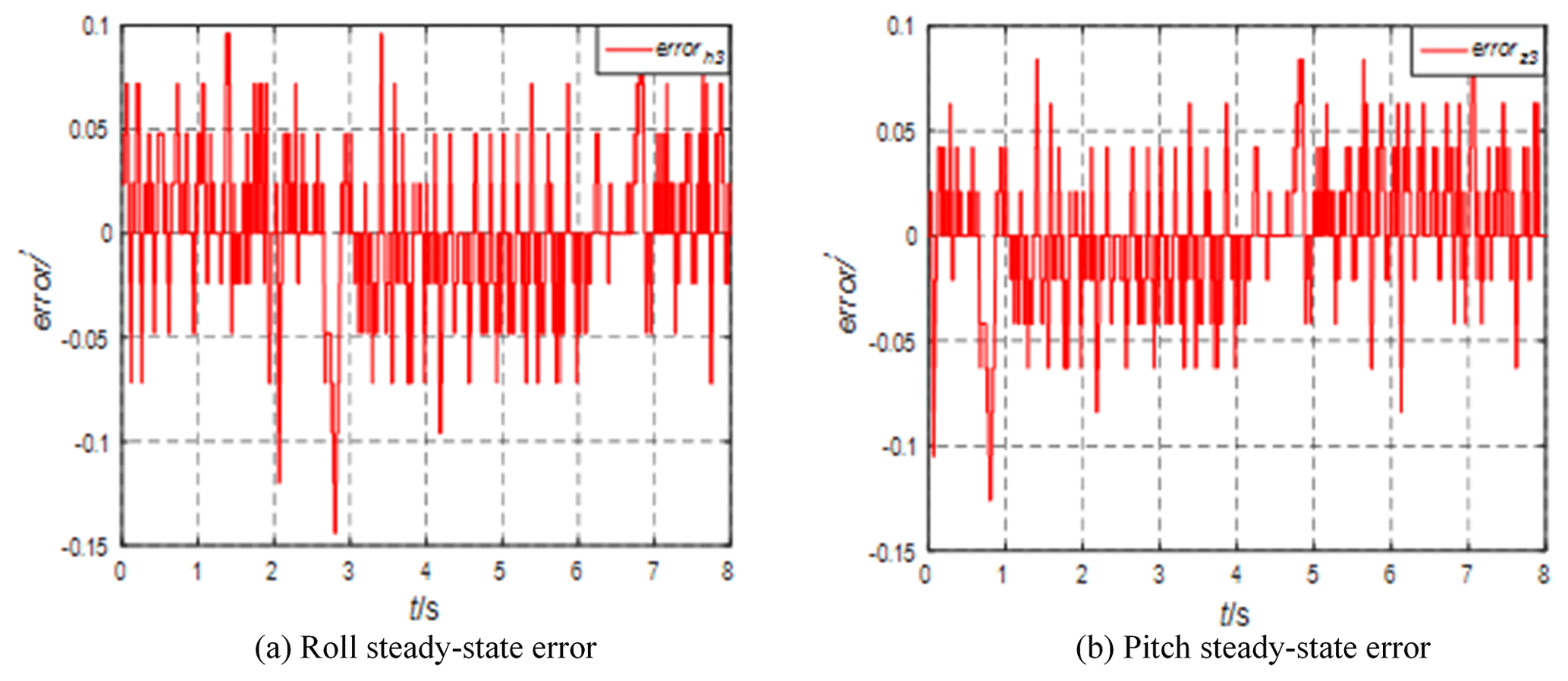
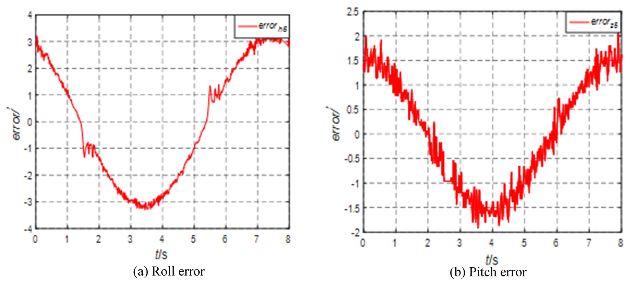
It can be seen from Fig. 10 that, when the swing table is not started, the steady-state accuracy of rolling and pitching is high and the error range is ± 0.1′. Start the swing platform, generate a sinusoidal motion with an amplitude of 15° and a period of 8 s, adjust the azimuth angle of the STSP to 0°, and analyze the rolling and pitching errors, as shown in Fig. 11.

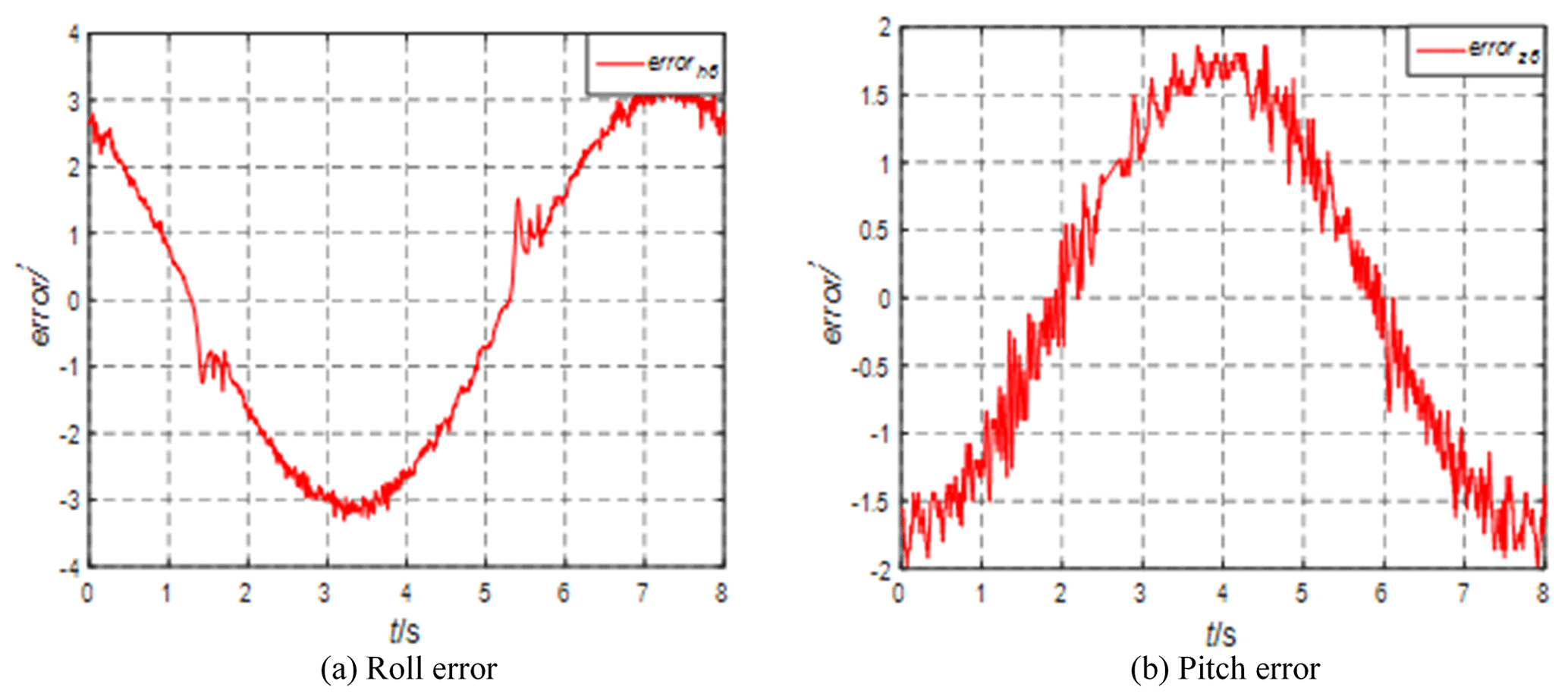
It can be seen from Fig. 11 that the roll angle error is close to 6′ and the pitch direction motion angle of the swing table is 0°. Under dynamic conditions, the platform pitch angle error is 0.2′. The swing table motion has a certain impact on the pitch direction, but the pitch stability accuracy is still high. Adjust the azimuth angle of the STSP to 45° and analyze the roll-and-pitch errors, as shown in Fig. 12.
It can be seen from Fig. 12 that the rolling error decreases and the pitch error is about 1.7′. The system runs stably, but the pitch error has many burrs, which is the same as the phenomenon of a single degree-of-freedom experiment. In the upper- and lower-limit reversing positions, there will be burrs with large amplitudes in rolling and pitching, which is related to the stress. Adjust the azimuth of the STSP to −45° and analyze the pitch-and-roll errors, as shown in Fig. 13.
It can be seen from Fig. 13 that azimuth reversal has little impact on roll-and-pitch errors, and the overall operation of the system is stable. Since the 3 degrees of freedom of the STSP move independently, there is no interference between them, so there is no impact on the errors.
Set the motion parameters of the swing table with amplitude 6° and period 4 s, adjust the azimuth to 45°, and observe the roll-and-pitch errors, as shown in Fig. 14.
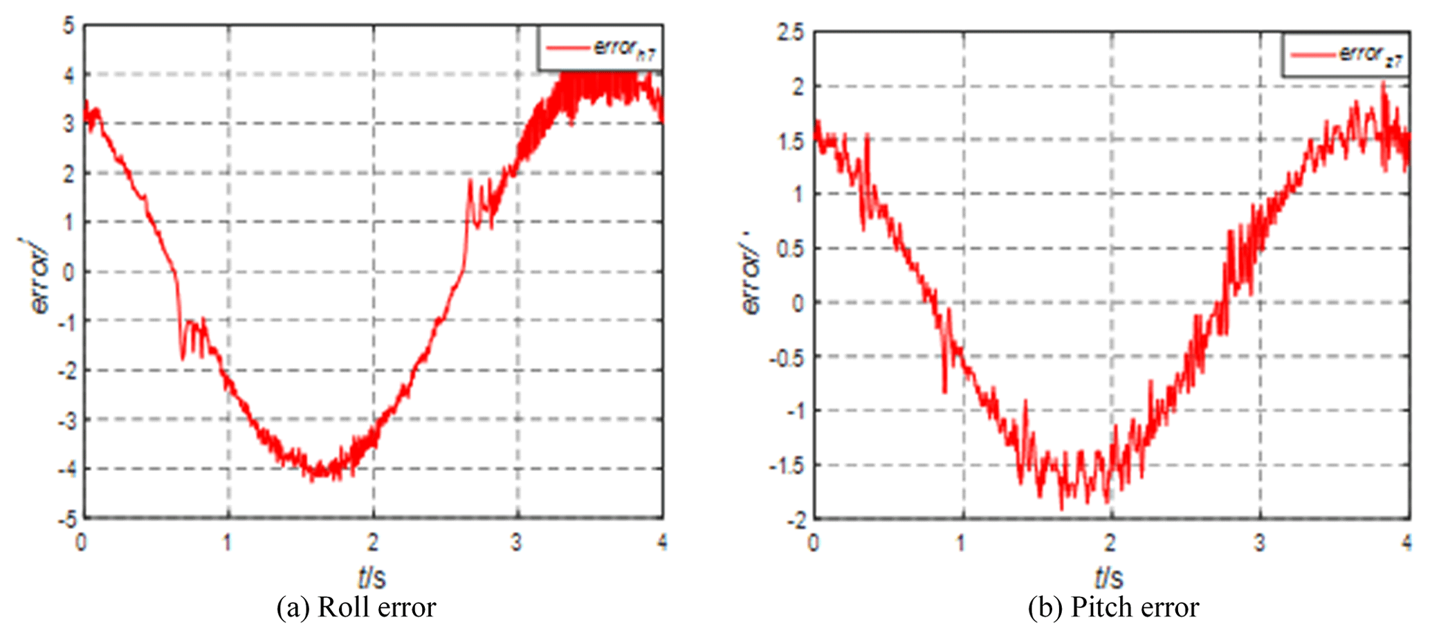
It can be seen from Fig. 14 that the increase in frequency makes the error larger. The roll error becomes larger when the speed is maximum. The pitch error changes little. The overall operation in both directions is stable, and the system works stably. Although there is a slight vibration, the amplitude is not large. The overall design is higher than the index requirements, the experimental and simulation results are almost consistent, and the control system is stable.
In this paper, a novel STSP is designed, its model is established, and its control system is designed. The kinematics and dynamics models of the STSP are established. The simulation experiments verify the accuracy of the forward and inverse kinematics and the force on the motors of each mechanism. The platform control system model is established, and the pitch system and roll system controllers are designed. The correctness of the controllers is verified by simulation. The experimental environment of the STSP prototype is established, the workflow of the platform control system is designed, and the prototype is tested to verify the feasibility of the prototype structure and the control system. The stability platform is installed on the swing platform for comprehensive experiments, and the errors of the various mechanisms at different azimuth angles are analyzed. The rationality of the platform structure, kinematics model, dynamics model, controller, and control system design are verified, which meets the requirements of practical application.
All the data and codes used in this paper can be obtained on request from the corresponding author.
DS and XX finished the modeling and analysis of the STSP. JM finished the design of the control strategy. LZ participated in the correction of the thesis.
The contact author has declared that none of the authors has any competing interests.
Publisher's note: Copernicus Publications remains neutral with regard to jurisdictional claims made in the text, published maps, institutional affiliations, or any other geographical representation in this paper. While Copernicus Publications makes every effort to include appropriate place names, the final responsibility lies with the authors.
The authors thank the editors and reviewers for their efforts.
This research has been supported by the National Natural Science Foundation of China (grant no. 61773007) and the Natural Science Foundation of Jilin Province (grant no. YDZJ202301ZYTS272).
This paper was edited by Daniel Condurache and reviewed by three anonymous referees.
Bras, S., Cunha, R., and Vasconcelos, J. F.: A nonlinear attitude observer based on active vision and inertial measurements, IEEE T. Robot., 27, 664–677, https://doi.org/10.1109/tro.2011.2112950, 2011.
Chen, C., Liu, Z., and Zhang, Y.: Actuator backlash compensation and accurate parameter estimation for active vibration isolation system, IEEE T. Ind. Electron., 63, 1643–1654, https://doi.org/10.1109/tie.2015.2497664, 2016.
Dasgupta, B. and Mruthyunjaya, T. S.: The Stewart platform manipulator: a review, Mech. Mach. Theory, 35, 15–40, https://doi.org/10.1016/s0094-114x(99)00006-3, 2000.
Guo, Q. Y. and Dan, T. J.: Robust H-infinity positional control of 2-DOF robotic arm driven by electro-hydraulic servo system, ISA T., 59, 55–64, https://doi.org/10.1016/j.isatra.2015.09.014, 2015.
Hilkert, J. M.: Inertially stabilized platform technology concepts and principles, IEEE Contr. Syst. Mag., 28, 26–46, https://doi.org/10.1109/MCS.2007.910256, 2008.
Huang, Q., Wang, P., Li, B., and Yang, Q.: Analysis and compensation control of passive rotation on a 6-DOF electrically driven Stewart platform, Mech. Sci., 12, 1027–1036, https://doi.org/10.5194/ms-12-1027-2021, 2021.
Jaime, G. and Alcaraz, L. A.: Kinematics of the gough-stewart platform by means of the newton-homotopy method, IEEE Lat. Am. T., 16, 2850–2856, https://doi.org/10.1109/TLA.2018.8804248, 2018.
Jun, H. and Feng, G.: Mechanism, actuation, perception, and control of highly dynamic multilegged robots: a review, Chin. J. Mech. Eng., 33, 1–30, https://doi.org/10.1186/s10033-020-00485-9, 2020.
Königseder, F., Kemmetmüller, W., and Kugi, A.: Attitude estimation using redundant inertial measurement units for the control of a camera stabilization platform, IEEE T. Contr. Syst. T., 24, 1837–1844, https://doi.org/10.1109/TCST.2015.2510324, 2016.
Kuseyri, S.: Modelling and stabilization of a three-axis ship-mounted mobile antenna system, P. I. Mech. Eng. M.-J. Eng., 231, 1–9, https://doi.org/10.1177/1475090216661908, 2016.
Li, Y., Yang, X., Wu, H., and Chen, B.: Optimal design of a six-axis vibration isolator via stewart platform by using homogeneous jacobian matrix formulation based on dual quaternions, J. Mech. Sci. Technol., 32, 11–19, https://doi.org/10.1007/s12206-017-1202-1, 2018.
Liu, X., Mao, J., and Yang, J.: Robust predictive visual servoing control for an inertially stabilized platform with uncertain kinematics, ISA T., 114, 347–358, https://doi.org/10.1016/j.isatra.2020.12.039, 2021.
Soltani, M. N., Izadi-Zamanabadi, R., and Wisniewski, R.: Reliable control of ship-mounted satellite tracking antenna, IEEE T. Contr. Syst. T., 19, 221–228, https://doi.org/10.1109/tcst.2010.2040281, 2011.
Slavutin, M. and Reich, Y.: Singularity analysis of some multi-platform mechanisms by decomposition and reciprocality, Mech. Mach. Theory, 146, 103735, https://doi.org/10.1016/j.mechmachtheory.2019.103735, 2020.
Slavutin, M., Sheffer, A., and Reich, Y.: A novel criterion for singularity analysis of parallel mechanisms, Mech. Mach. Theory, 137, 459–475, https://doi.org/10.1016/j.mechmachtheory.2019.03.001, 2019.
Song, Y., Hao, G., and Tao, S.: Kinematic analysis and optimal design of a novel 1T3R parallel manipulator with an articulated travelling plate, Robotics & Computer Integrated Manufacturing, 30, 508–516, https://doi.org/10.1016/j.rcim.2014.03.006, 2014.
Tian, C. and Zhang, D.: A new family of generalized parallel manipulators with configurable moving platforms, Mech. Mach. Theory, 153, 103997, https://doi.org/10.1016/j.mechmachtheory.2020.103997, 2020.
Tian, C., Fang, Y., and Ge, Q. J.: Structural synthesis of a class of two-loop generalized parallel mechanisms, Mech. Mach. Theory, 128, 429–443, https://doi.org/10.1016/j.mechmachtheory.2018.06.008, 2018.
Wang, C., Fang, Y., and Fang, H.: Novel 2R3T and 2R2T parallel mechanisms with high rotational capability, Robotica, 35, 401–418, https://doi.org/10.1017/s0263574715000636, 2017.
Wang, W., Zhang, J., and Kong, D.: Research on control method of upper limb exoskeleton based on mixed perception model, Robotica, 40, 3669–3685, https://doi.org/10.1017/S0263574722000480, 2022.
Yang, C., Ye, W., and Li, Q.: Review of the performance optimization of parallel manipulators, Mech. Mach. Theory, 170, 104725, https://doi.org/10.1016/j.mechmachtheory.2022.104725, 2022.
Yu, L. A., Bl, B., and Wx, C.: A method for measuring the inertia properties of a rigid body using 3-URU parallel mechanism, Mech. Syst. Signal Pr., 123, 174–191, https://doi.org/10.1016/j.ymssp.2019.01.013, 2019.
Zhang, J., Song, Y., and Liang, D.: Mathematical modeling and dynamic characteristic analysis of a novel parallel tracking mechanism for inter-satellite link antenna, Appl. Math. Model., 93, 618–643, https://doi.org/10.1016/j.apm.2020.12.020, 2021.
- Abstract
- Introduction
- Overall scheme design of the series three-axis stable platform (STSP)
- Modeling and analysis of the STSP
- Modeling and analysis of the STSP control system
- STSP system experiment
- Conclusion
- Code and data availability
- Author contributions
- Competing interests
- Disclaimer
- Acknowledgements
- Financial support
- Review statement
- References