the Creative Commons Attribution 4.0 License.
the Creative Commons Attribution 4.0 License.
 | 27 Feb 2024
Vibration coupling characteristics and grinding force control of an elastic component grinding system
Yufei Liu
Lang Wu
En Lu
Jinyong Ju
A system's dynamic behavior and vibration mechanism during interaction with a workpiece are the key factors for the stability control of the robotic grinding operation. This paper investigates the vibration coupling effect and grinding force control of the elastic component grinding system (ECGS), which is a multi-dimensional coupling system conveying a dynamic interaction between the elastic component and the grinding device during the grinding process. An elastic constraint model with equivalent stiffness is constructed to describe the dynamic disturbance effect of the elastic vibration of the elastic component. Then, the rigid–flexible coupling dynamic model of the ECGS is established. And the elastic vibration behavior of the elastic component and the grinding force fluctuation characteristics under the vibration coupling are analyzed for revealing the coupling relationship between the elastic vibration and the grinding force. Finally, through the pneumatic servo control, the grinding force adaptive controller is designed to realize the compensation control of the grinding force under the vibration coupling of the elastic component. The effectiveness of the control strategy is verified by the virtual prototype co-simulation experiment and the real prototype experiment.
- Article
(4847 KB) - Full-text XML
- BibTeX
- EndNote


Compared with conventional manual grinding and machine grinding methods, robotic grinding is characterized by high flexibility and low cost, and it has significant advantages in the manufacturing and processing of large workpieces. For robotic grinding, deburring (Zhang et al., 2006; Song and Song, 2013; Villagrossi et al., 2018), polishing (Dai et al., 2022; T. Zhang et al., 2020a; J. Z. Xu et al., 2019) and other contact processing operations, the constant force control is one of the key problems that should be solved.
In order to realize the constant force control of robotic machining, there are two methods that are mainly used at present (Huang et al., 2017). One is active control where the force control is realized through the robot body. The other is passive control where the robot is responsible for the trajectory control when the end device realizes the contact force control by adding a flexible joint to the robot end. For the active control method, there is a coupling effect of the force control and the position control, which increases the control difficulty. Aiming at curved surfaces, Tian et al. (2016a, b) investigated the modeling and controller design of a robotic automatic polishing system, and the constant force control was realized. Ding et al. (2019) studied the influence of the system stiffness on the force-tracking performance and realized stable force and accurate position control through the position adaptive stress-position hybrid control algorithm. Dong et al. (2020) proposed a hybrid position/force control method based on the internal joint torque controller, which realized precise force control of the robot in actual surface polishing. Based on the hybrid force/position control strategy, H. Zhang et al. (2020) proposed a multi-source parameter gravity compensation algorithm to identify the unknown parameters of the robot grinding system and realized the active force control. X. Xu et al. (2019, 2021) introduced a force/position control method to reduce the overcut and undercut phenomena in robot belt grinding of the turbine blades, and mixed force control was achieved.
Passive compliance control can reduce the dependence on the robot body and realize the decoupling of the force and position control, which has been widely investigated in robotic machining in recent years. Zhao and Shi (2013) designed a pneumatic flexible polishing mechanism and proposed a dual-mode switching compound adaptive control strategy to realize the high-precision control of polishing force. Du et al. (2015) designed a flexible end effector with integrated force sensor for automatically polishing the curved parts; then the polishing contact force control was realized with the designed adaptive anti-saturation integral separation fuzzy-PI (proportional–integral) controller combined. Mohammad et al. (2018, 2019) proposed a kind of auto-polishing force-controlled end actuator, which can control the polishing force by controlling the expansion and contraction of the hollow voice coil actuator. Chen et al. (2019) designed a novel intelligent end effector, with a force sensor and an eddy current damper integrated, for controlling contact force and suppressing spindle vibration. Based on pneumatic artificial muscles and a four-bar connection mechanism, Wang et al. (2021) designed a novel end effector for suppressing the vibration of a thin-walled workpiece during the grinding operation. Ding et al. (2021) proposed a constant force mechanism based on the combination of a folded beam and a bistable beam mechanism, and the effective control of the deburring contact force of the workpiece is realized. Zhou et al. (2021) designed an electrically driven linear end effector to achieve the adaptive stress control and the position-tracking control for polishing based on the adaptive impedance controller. J. Wang et al. (2022) designed a parallel robot with a pneumatic constant-force actuator to demonstrate the feasibility of the constant-force control.
However, the existing research on the force control of a robotic machining system mainly focuses on the rigid components, while research on the elastic components is still lacking. As we all know, the application of the elastic components such as elastic thin-walled structures is more and more extensive, and the manufacturing and processing of large elastic components have high requirements for the flexibility of manufacturing systems. Existing research has shown that an elastic thin-walled workpiece has the characteristics of large structure size and low stiffness. And it is easy to produce elastic vibration during machining, which presents a challenge for the robotic grinding system (Chai et al., 2017; Sina and Haddadpour, 2014; Wang and Qin, 2016). With the helical angle effect of the tool and the dynamic characteristics of the thin-walled parts considered, Jin et al. (2016) proposed a method to obtain three-dimensional stable blades for the vibration control of the elastic thin-walled parts. By optimizing fixture and cutting parameters, Wang et al. (2018) reduced the elastic deformation of the thin-walled workpiece during machining and improved the machining accuracy of the thin-walled elastic workpiece. Aiming at the chattering of the microscale thin-walled parts in high-speed micro-milling, Jia et al. (2021) established the milling force model, which provides a basis for selecting cutting parameters to achieve stable cutting. Jiang et al. (2022) designed a magnetorheological damping fixture to suppress the system vibration generated during the semi-active machining of thin-walled parts for aerospace. Liu et al. (2023) established a coupling dynamic model of the grinding system and investigated the dynamic coupling effect between the elastic component and the grinding spindle. Obviously, it is obtained from the above literature that the robotic grinding system is a multi-dimensional coupled system, and the vibration coupling effect of the grinding system, especially for the elastic components, should be further investigated, which is significant for the grinding force control.
In this paper, the vibration coupling characteristics and grinding force control of the elastic component grinding system (ECGS) are studied. By establishing the dynamic coupling model of the ECGS, the fluctuation characteristics of the grinding force under the vibration coupling of the elastic components were analyzed, and the dynamic coupling behavior of the system was revealed. On this basis, the constant control of the grinding force under vibration coupling was realized. The sections of this paper are arranged as follows. In Sect. 2, the rigid–flexible coupling dynamic model of the ECGS is established. In Sect. 3, the vibration characteristics of the elastic components as well as the grinding force characteristics of the system under vibration coupling are studied. In Sect. 4, a grinding force adaptive controller is designed. And the virtual prototype co-simulation experiment and the real prototype experiment are carried out in Sect. 5 for verifying the effectiveness of the proposed controller. Finally, Sect. 6 gives a brief summary.
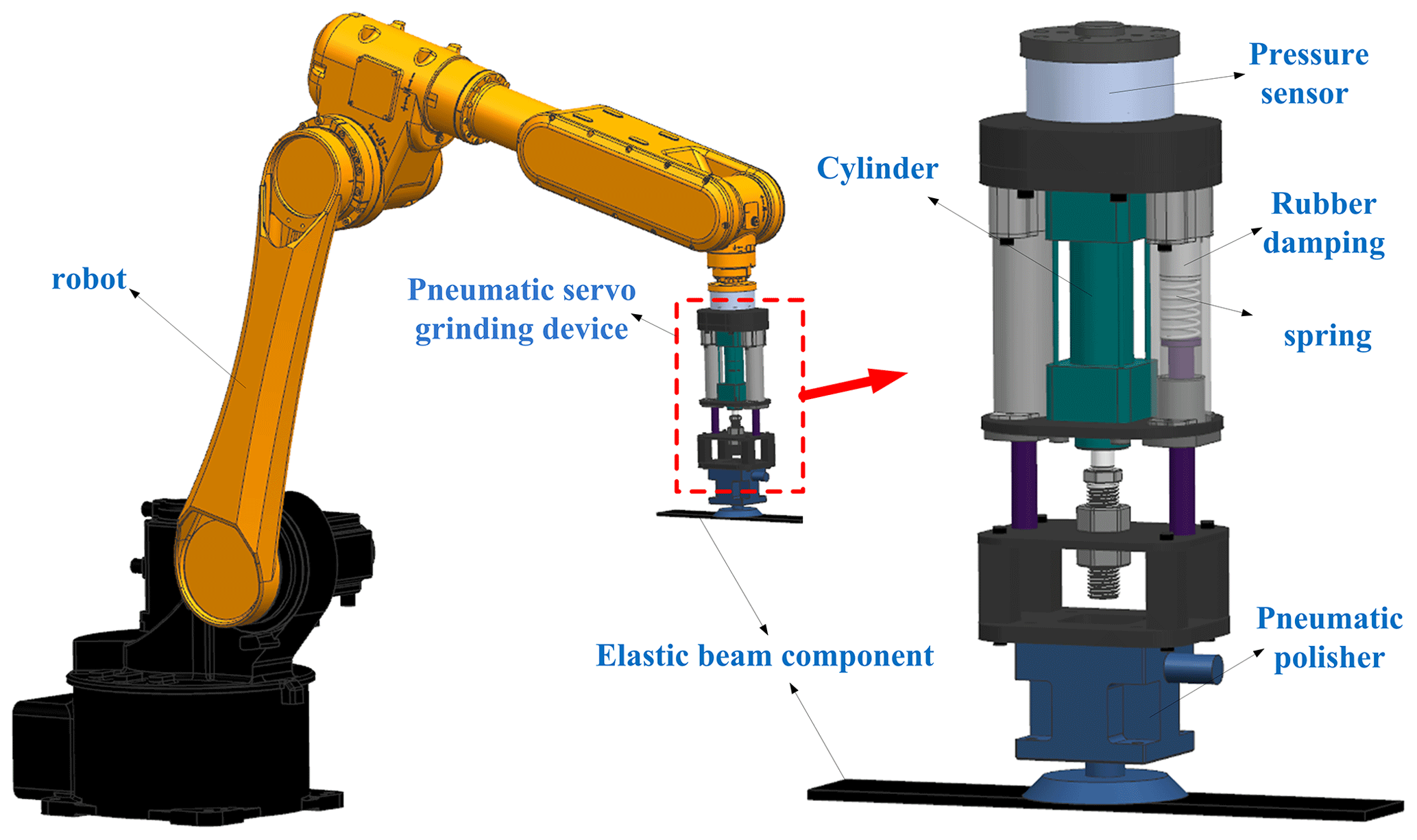
As shown in Fig. 1, the robotic grinding system is composed of the robot, the designed pneumatic servo grinding device and the workpiece, which is a typical multi-dimensional coupling system. And the pneumatic servo grinding device includes the cylinder, the pneumatic grinder, the pressure sensor and connecting attachments. In the grinding system, the grinding force is a key factor that influences the grinding stability and quality. To realize the decoupling control of the grinding force and the position, the grinding device is responsible for the grinding force control, while the robot realizes the grinding trajectory. The elastic component studied in this paper, which has low stiffness, is easy to excite a time-varying elastic vibration during the grinding process and affects the grinding force. In this case, the dynamic coupling relationship between the elastic component and the grinding device is significant for the grinding force control of the robotic grinding system.
To study the dynamic interaction between the elastic component and the grinding device during the grinding process, an elastic beam component (EBC) is employed to characterize the elastic component, and an equivalent stiffness elastic constraint model is established. It is assumed that the EBC is continuously distributed with linear constraint springs along the grinding direction, and the equivalent stiffness of the constraint spring is expressed as k(x), which changes with the grinding position. In this case, the rigid–flexible coupling dynamic model of the ECGS is established as shown in Fig. 2.

Based on the force analysis at the grinding position, one can obtain
where M is the equivalent mass of the grinding device; is the equivalent damping of the grinding device, where Cp is the viscous damping coefficient of the cylinder and c is the damping coefficient of the rubber; is the equivalent stiffness of the grinding device, where Kp is the equivalent stiffness coefficient of the cylinder and kt is the stiffness coefficient of the spring; P1 is the pressure of the rodless chamber of the cylinder, A1 is the stressed area of the rodless chamber of the cylinder; P2 is the pressure of the rod chamber of the cylinder, A2 is the stressed area of the rod chamber of the cylinder; Ff is the friction force on the cylinder; Fp is the output force of the cylinder; and z is the displacement of the cylinder.
According to the force balance relationship, the grinding contact force at the grinding position can be expressed as
where z(x,t) is the transverse vibration displacement of the EBC at the grinding point, which is equal to the output displacement of the cylinder.
According to Eq. (2), in order to analyze the grinding contact force, the vibration displacement and the equivalent stiffness of the EBC at the grinding position should be determined.
As shown in Fig. 2, the grinding contact force can be divided into the tangential grinding force (Ft), axial grinding force (Fa) and the normal grinding force (Fn) along the three directions of the grinding grain X, Y and Z. During the grinding process, the normal grinding force is the main parameter that needs to be considered in the constant force control of grinding. The concentrated force acting on the point (vwt) of the EBC is the normal grinding force. Then, the transverse force acting on the EBC can be shown as
where vw is the grinding feed speed, and ε(x−vwt) is the unit pulse function. In general, the normal grinding force is 1.5–3 times more than the tangential grinding force, which is specifically related to the abrasive particle and the workpiece material (Yin and Zhou, 2017; Li et al., 2016). In this paper, it is selected that .
Referring to the grinding parameters and surface grinding conditions in the literature (Yin and Zhou, 2017; D. Wang et al., 2022; Zhang et al., 2014), the normal grinding force in this paper is defined as
where CF is the cutting proportion constant; ap0 is the ideal grinding depth; vs is the grinding plate linear speed.
Based on the dynamic model and the coupling relationship, the transverse vibration displacement of the EBC will cause the fluctuation of the grinding depth, and in this case, the normal grinding force can be expressed as
The generalized force in modal coordinates of the EBC can be described as
where Yi(vwt) is the value of the ith mode shape function of the EBC at x=vwt.
Considering the machining method of the EBC with fixed ends, the modal shape functions of the EBC can be described as (Qiu et al., 2021)
where λi=βil, wherein l is the length of the EBC and βi is the constant coefficient which is related to the boundary conditions. The natural frequency of the EBC can be described as
where E is the elastic modulus of the EBC, I is the moment of inertia of the section of the EBC, ρ is the density of the EBC, and A is the cross-sectional area of the EBC.
The vibration differential equation of the EBC in generalized coordinate form under grinding condition can be obtained as
where qi and Mi are the ith mode coordinate and the ith mode mass of the EBC, respectively. Mi can be expressed as
According to Duhamel's integral, by substituting Eq. (10) into Eq. (9), the solutions of qi can be obtained as
where qi0 and represent the initial displacement and initial velocity in generalized coordinate form, respectively.
According to the mode superposition principle (Rao, 2011), the vibration displacement equation can be expressed as
According to the elastic constrained model of the ECGS as shown in Fig. 2, the disturbance effect of the elastic vibration of the EBC on the grinding contact force is characterized by constraint spring with variable equivalent stiffness, which changes with the grinding positions. In order to determine the equivalent stiffness of the EBC at the grinding positions, it is assumed that the two ends of the EBC are fixed constraints.
As shown in Fig. 3, under the action of the normal grinding force, according to the static equilibrium conditions of the EBC, the reaction forces of the supports can be expressed as
where a is the length of AC section of the EBC, and b is the length of BC section of the EBC.
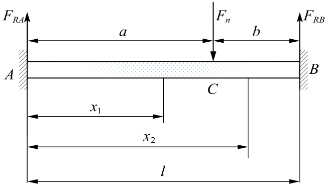
Then, the bending moments of the AC section and the BC section can be expressed as
where x1 is the AC section variable; x2 is the BC section variable.
By integrating Eq. (14), the angle equation and the deflection line equation of AC section can be obtained as
Similarly, the angle equation and the deflection line equation of BC section can be got as
According to the continuity conditions and boundary conditions, one can obtain
By substituting Eqs. (15)–(16) into Eqs. (17)–(18), the deflection of the EBC can be shown as
where is the maximum deflection of the EBC under stress.
According to Hooke's law, the equivalent stiffness of the EBC can be expressed as
where is the maximum deflection of the EBC under the normal grinding force.
According to Fig. 3, it is obvious that a=x and , by substituting them into Eq. (20), the equivalent stiffness of the EBC can be further shown as
Substituting Eqs. (12) and (21) into Eq. (2), one can obtain
Equation (22) shows the grinding contact force equation at different grinding positions with the vibration coupling of the EBC considered. It is intuitively seen that there is a coupling relationship between the vibration of the EBC and the grinding contact force.
In order to investigate the vibration coupling characteristic of the EBC during the robot grinding process, the dynamic simulation model of the ECGS is built in MATLAB2018/Simulink as shown in Fig. 4, which mainly includes the vibration-displacement-solving module, the equivalent-stiffness-solving module and the grinding-force-solving module. During the simulation process, it is assumed that the expected grinding contact force is 15 N, and the simulation parameters are shown in Table 1.
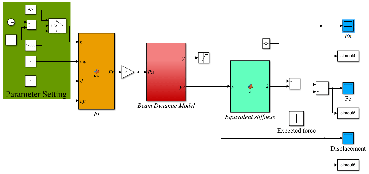
Table 1Parameters of the dynamic simulation model of the ECGS.
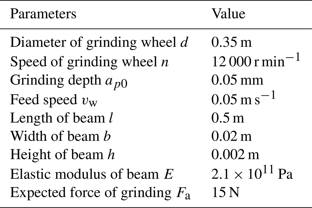
Figure 5 shows the vibration response of the EBC with different thicknesses; it is seen that the EBC exhibits obvious vibration in the grinding process and presents time-varying characteristics with the change of the grinding points. The vibration amplitude reaches the largest value near the middle position of the EBC. And the thinner the EBC, the larger the vibration amplitude.
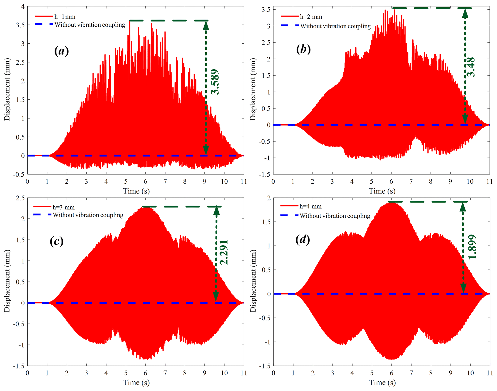
Figure 5Vibration characteristics of the EBC with different thicknesses: (a) h = 1 mm; (b) h = 2 mm; (c) h = 3 mm; (d) h = 4 mm.
Figure 6 shows the grinding contact force characteristics of the EBC with different thicknesses under vibration coupling. It is seen that the grinding contact force of the EBC fluctuates significantly during grinding and has time-varying characteristics with the change of the grinding positions, which is obviously different from that of the rigid component. At the same time, the fluctuation amplitude of the grinding contact force increases with the decrease of the workpiece thickness.
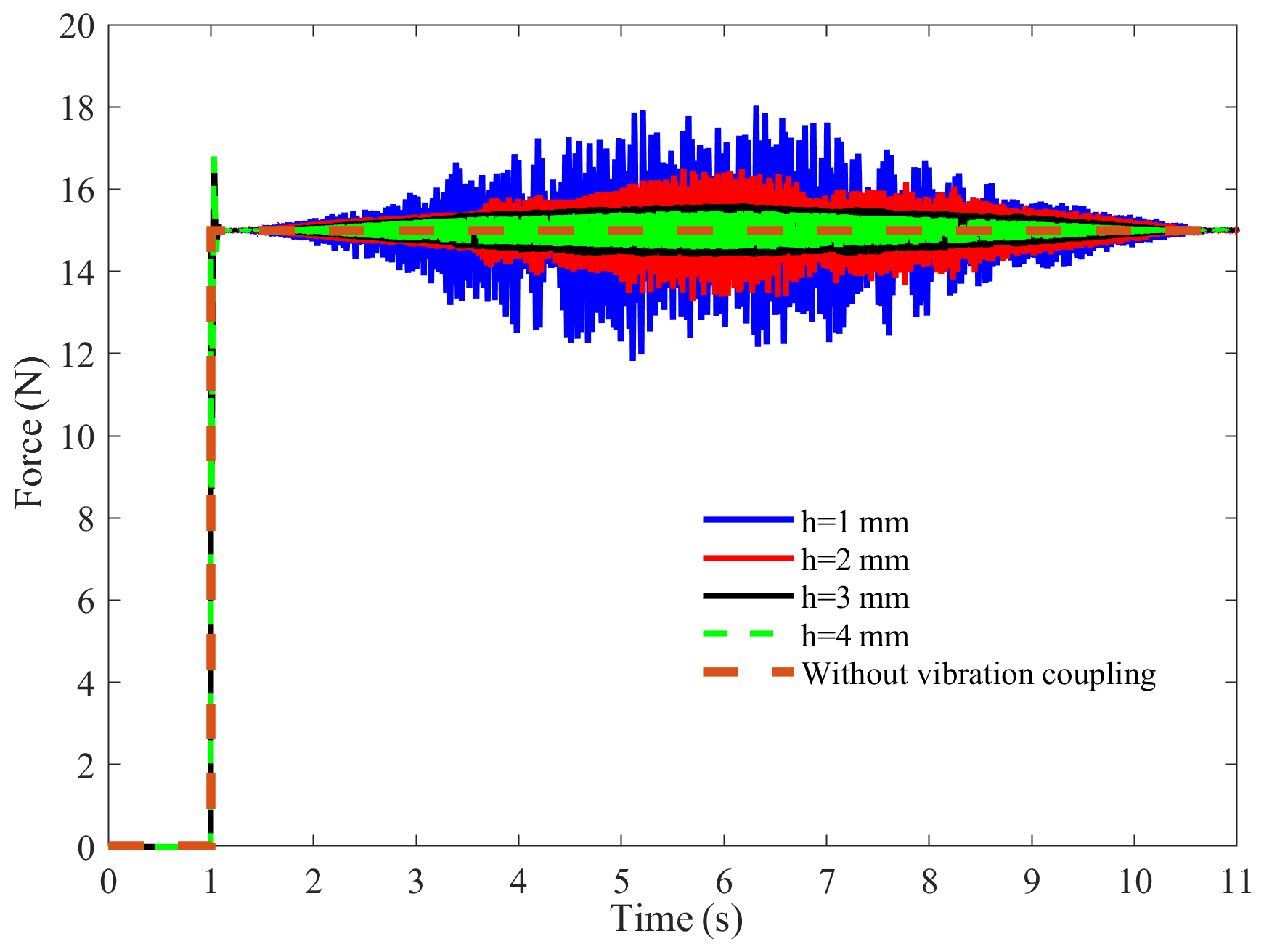
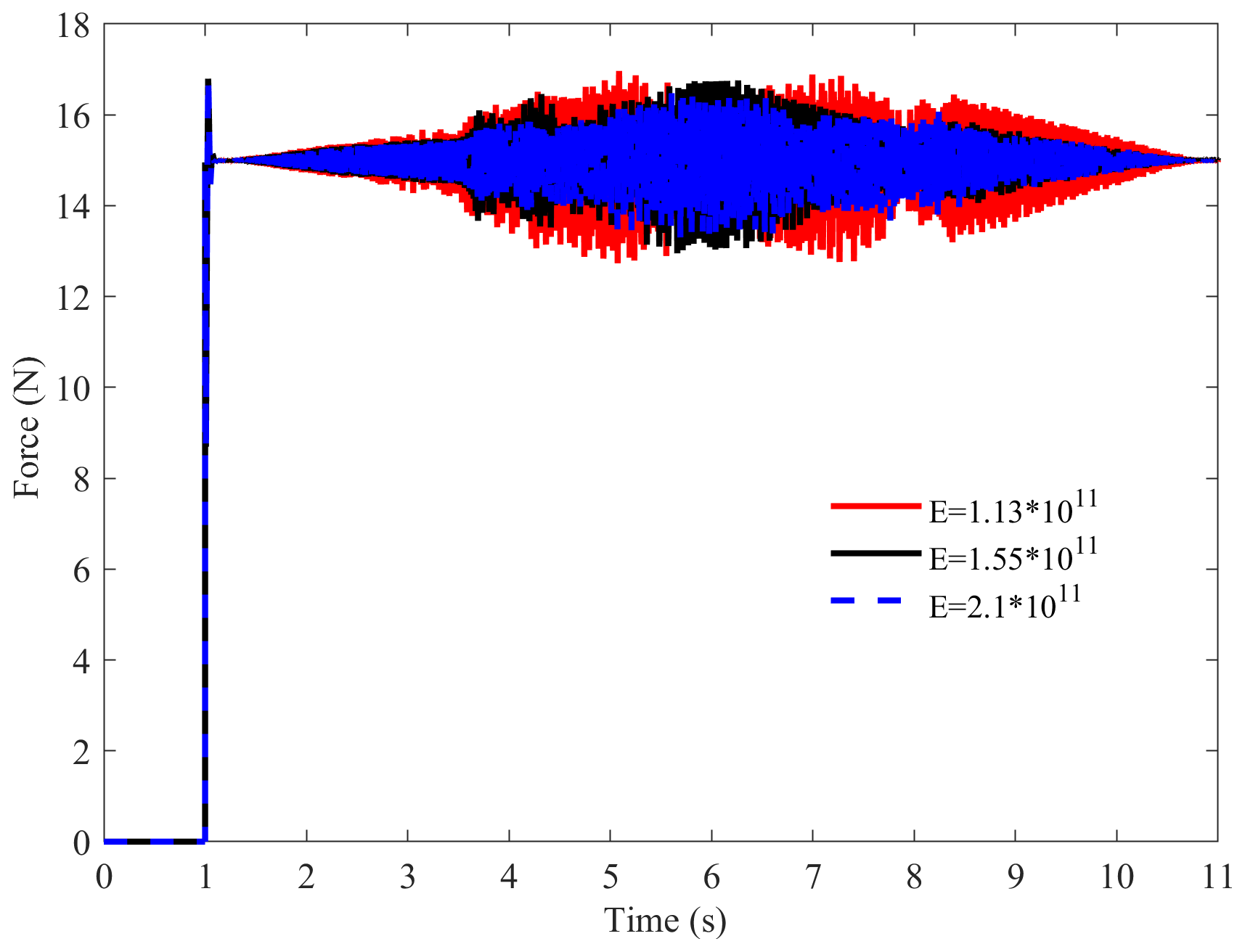
Figure 7 shows the grinding contact force characteristics of the EBC with the same structural parameters and different materials. In order to analyze the influence of the materials, grey cast iron, malleable cast iron and carbon steel were selected, and their corresponding elastic modulus values are 1.13 × 10¹¹, 1.55 × 10¹¹ and 2.10 × 10¹¹ pa, respectively. The results show that the EBC material has a certain influence on the grinding contact force characteristics, and the fluctuation amplitude of the grinding contact force increases with a decrease of the elastic modulus.
According to the above analysis, the EBC has obvious elastic vibration during the grinding process, and there is a certain coupling relationship between the elastic vibration and the grinding contact force. Therefore, it is necessary to consider the vibration coupling of the EBC to compensate the grinding contact force during the grinding process.
4.1 Pneumatic servo equation
In this section, based on the coupling relationship of the grinding system and the pneumatic servo control of the grinding device, the grinding contact force control under the vibration coupling is studied.
During the analysis, the influence of the friction force inside the pneumatic servo system is ignored. By performing a Laplace transform on Eq. (1), one can obtain
Based on the Sanville flow formula (Tressler et al., 2002), the mass flow formula of a proportional valve port is
where At=πDxv is the opening area of the valve port, wherein D is the spool diameter and xv is the spool displacement; Pu is the absolute pressure at the intake port of the proportional control valve; Pd is the absolute pressure of proportional adjustment of the air outlet; R is the ideal gas constant; T is the thermodynamic temperature of the gas; and μ is the flow coefficient. And the express of ) can be shown as
where k is the gas isentropic index.
It is assumed that there is a linear relationship between the spool displacement and the input voltage, then the spool displacement can be represented as
where Ku is the gain coefficient of the proportional valve, u is the input voltage.
The gas flow increment model and the cylinder chamber flow model of the rodless chamber and the rod chamber for the cylinder under ideal state can be obtained as (T. Zhang et al., 2020b)
where K1 is the voltage amplification factor of the rodless chamber, K2 is the pressure amplification factor of the rodless chamber, K3 is the voltage amplification factor of the rod chamber, K4 is the voltage amplification factor of the rod chamber, V1 is the volume of the rodless chamber, and V2 is the volume of the rod chamber.
It is assumed that the inlet pressure of the gas pipe is equivalent to the outlet pressure of the servo valve. With Eqs. (27) and (28) combined, one can obtain
Substituting Eq. (29) into Eq. (23) with Fp(s)=0, the transfer function between the piston displacement of the cylinder and the input voltage of the proportional valve can be got as
where , , a3=MV1V2, and .
Similarly, by substituting Eq. (29) into Eq. (23) with U(s)=0, the transfer function between the cylinder piston displacement and the cylinder thrust can be expressed as
If the input load force value of the pneumatic system is equal to the output force value of the pneumatic system and the direction of the force is opposite, the transfer function between the cylinder thrust and the input voltage of the proportional valve can be expressed as
Equation (32) directly reflects the relationship model between the control amount of the grinding device and the cylinder thrust. Substituting Eq. (32) into Eq. (2), the grinding contact force of the elastic component can be obtained as
It is seen that there is a coupling relationship between the grinding contact force and the pneumatic servo system under the vibration coupling of elastic components. In this case, the compensation control of the grinding contact force can be realized through the pneumatic servo control.
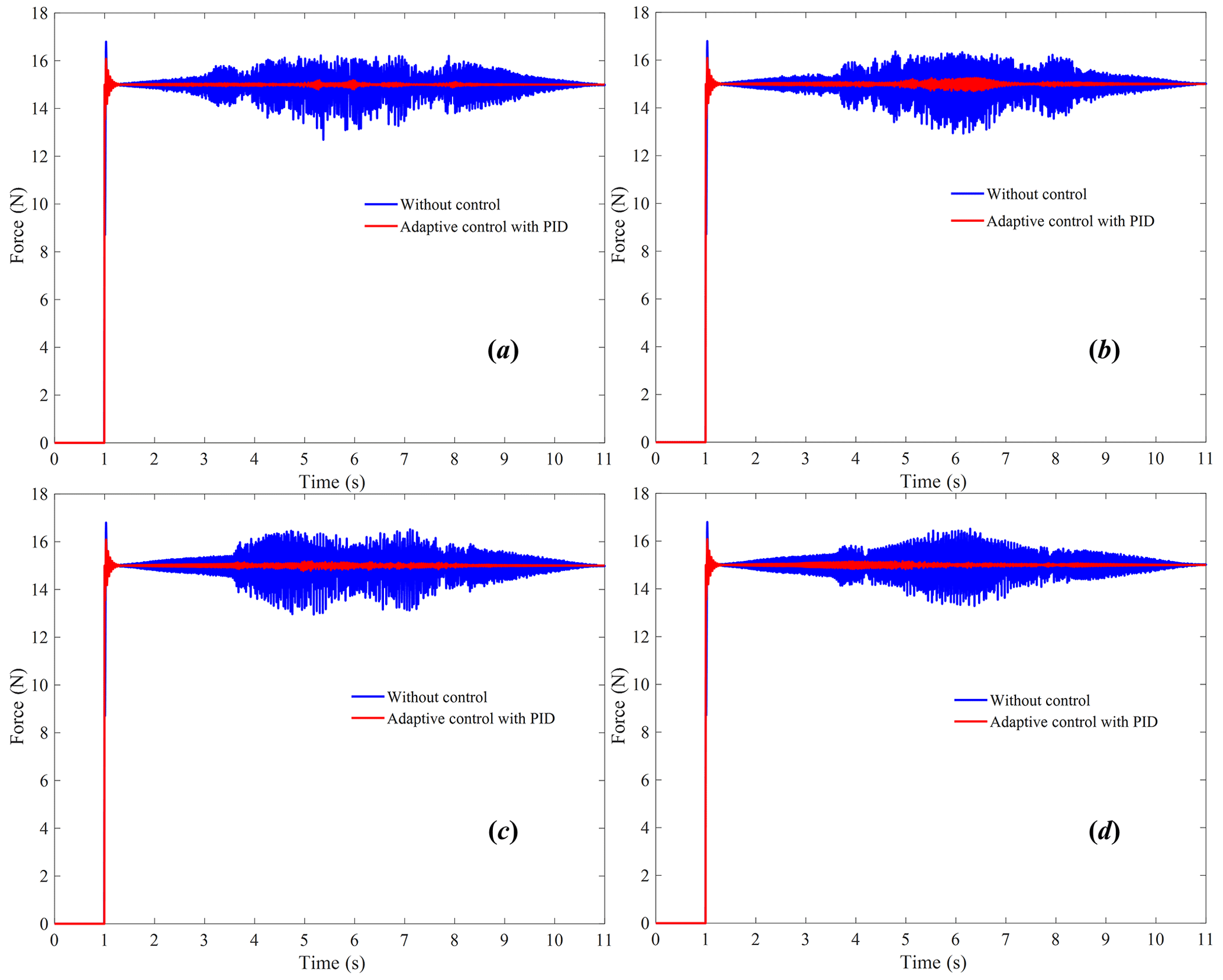
Figure 10Simulation results of adaptive control of grinding contact force under vibration coupling of the EBC: (a) S = 3000 r min−1; (b) S = 6000 r min−1; (c) S = 9000 r min−1; (d) S = 12 000 r min−1.
In order to effectively control the output force of the cylinder, the pneumatic servo system should be stable. Based on Eq. (32), the characteristic equation of the pneumatic servo system can be obtained as
According to Hurwitz's stability criterion, the Hurwitz determinant of the pneumatic servo system can be expressed as
By substituting the relevant system parameters, one can obtain that det(H)>0 . It is seen that the pneumatic servo system is stable.
4.2 Grinding force adaptive controller design
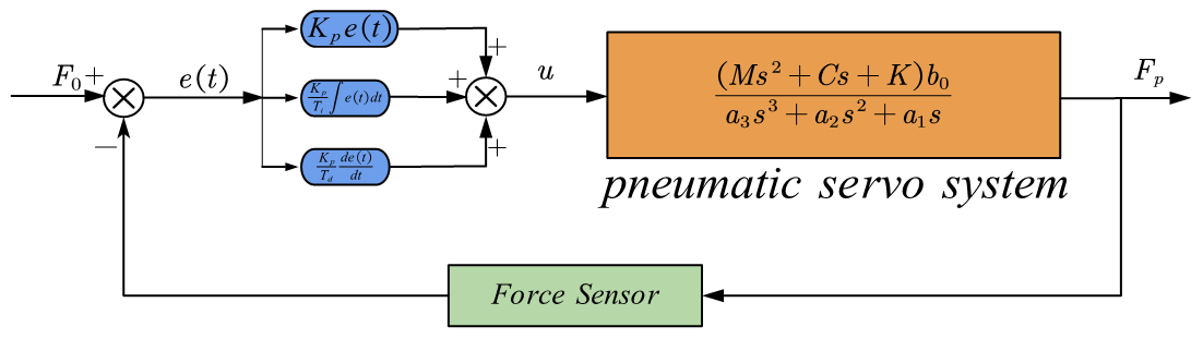
The grinding force adaptive controller for the grinding contact force of the EBC is designed based on the PID (proportional–integral–differential) controller and the pneumatic servo system. Moreover, the constant control of the grinding contact force under vibration coupling of the EBC can be realized through pneumatic servo control. As shown in Fig. 8, by feeding the actual grinding contact force back to the grinding force adaptive controller, the constant control of the grinding contact force of the EBC was realized by adjusting the voltage of the electromagnetic servo valve. The variables in Fig. 8 are explained as follows: F0 is the desired grinding contact force, Kp is the proportional gain coefficient, Ti is the integral time constant and Td is the differential time constant.
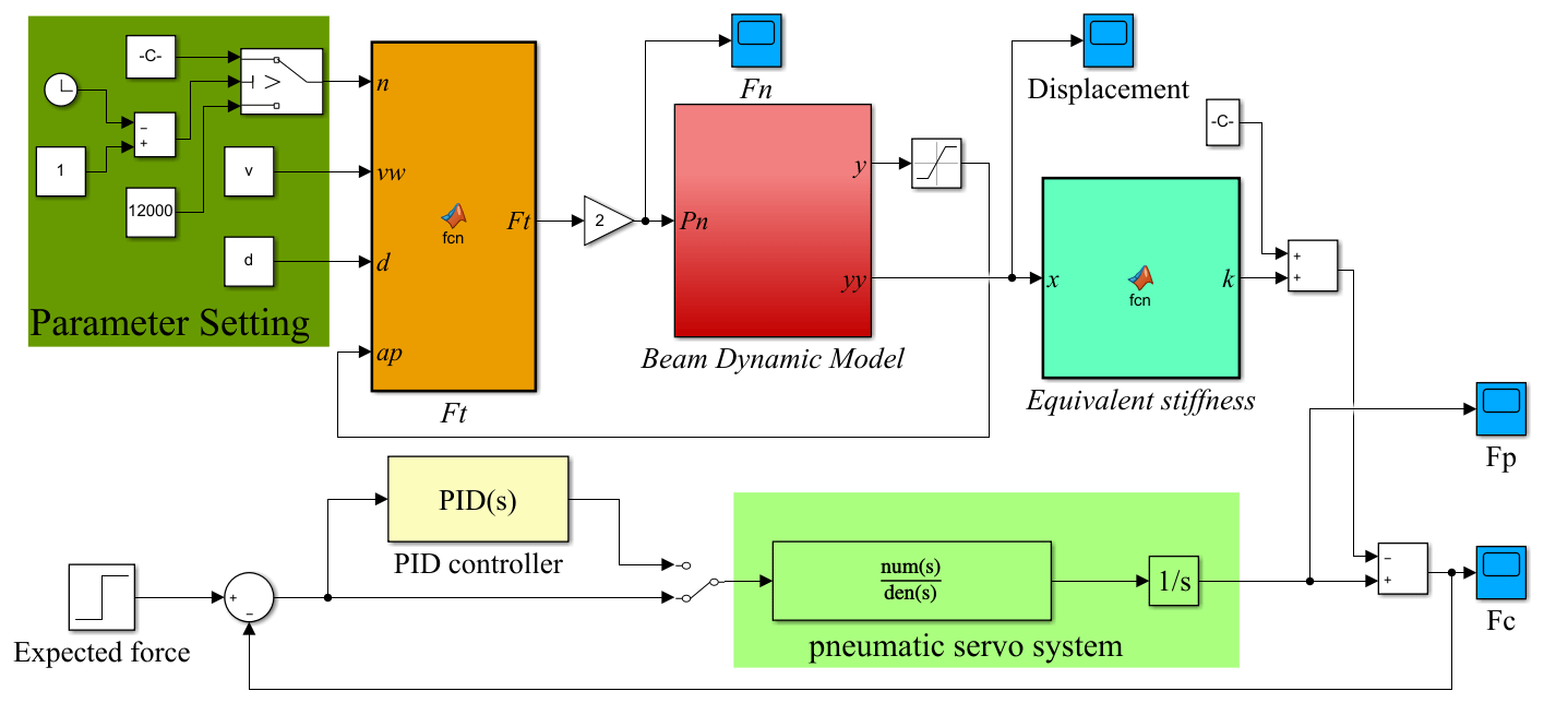
In order to verify the effectiveness of the control strategy, MATLAB2018/Simulink was used to build an adaptive control simulation model for grinding contact force of the ECGS, which is shown in Fig. 9. And the ECGS parameters are shown in Table 2.
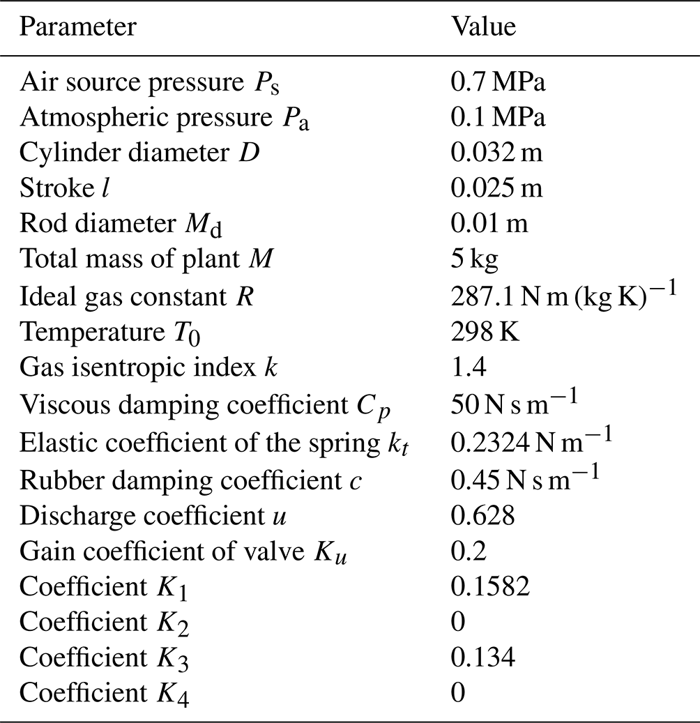
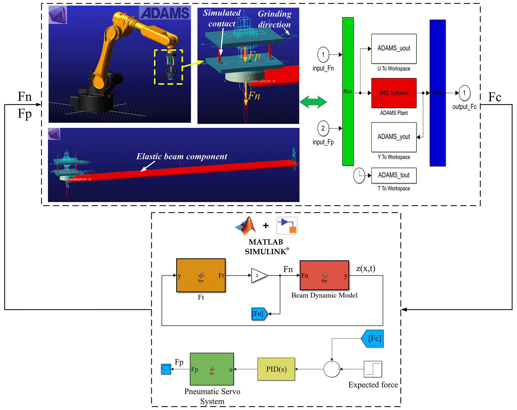
Figure 10 shows the adaptive control effect of the grinding contact force under vibration coupling of the EBC. In the simulation process, the grinding speeds are selected as 3000, 6000, 9000 and 12 000 r min−1. It is seen that the designed grinding force adaptive controller can suppress the grinding contact force fluctuation under the vibration coupling of the EBC with different grinding speeds; thus, the effectiveness of the designed control strategy can be verified.
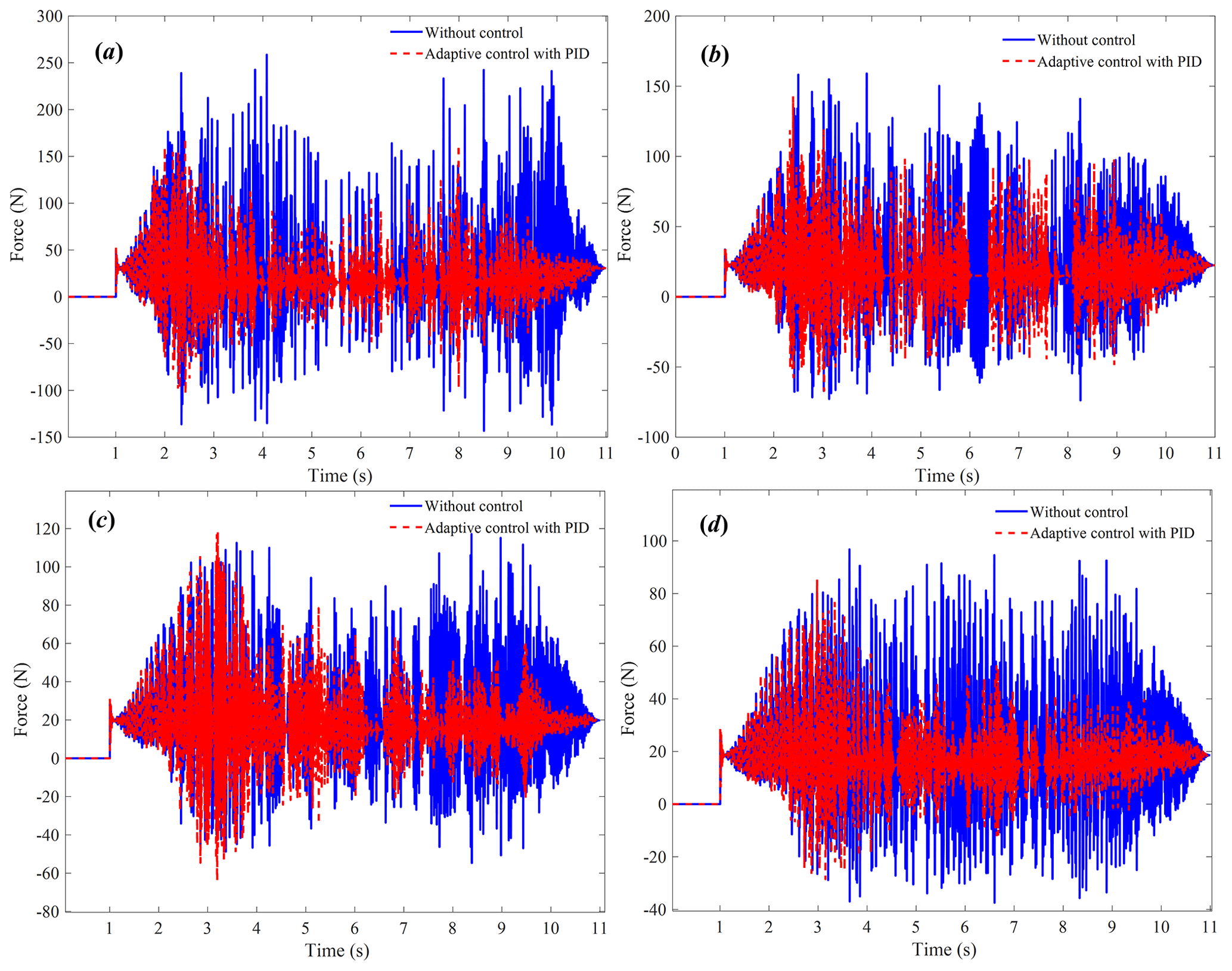
Figure 12Results of co-simulation experiment on grinding contact force control with different speeds: (a) S = 3000 r min−1; (b) S = 6000 r min−1; (c) S = 9000 r min−1; (d) S = 12 000 r min−1.
5.1 Virtual prototype co-simulation experiment
In order to further verify the designed adaptive control strategy of the grinding contact force, a virtual prototype model of the EBC was built to perform simulation experiments. Combining the designed grinding force adaptive controller with the virtual prototype model of the EBC, a co-simulation experimental system of the ECGS was established, as shown in Fig. 11. In the simulation experiment, the output thrust and grinding force of the pneumatic servo control system are applied to the EBC to characterize the force action during the grinding process of the EBC. Meanwhile, the grinding contact force of the EBC is fed back to the pneumatic servo control system in real time to verify the effect of the grinding force adaptive controller.
Figure 12 shows the co-simulation experiment results with different grinding speeds. It is seen that the designed grinding force adaptive controller plays a certain role in suppressing the grinding contact force fluctuation under the vibration coupling of the EBC, which verifies the effectiveness of the grinding force adaptive controller.
5.2 Prototype experiment
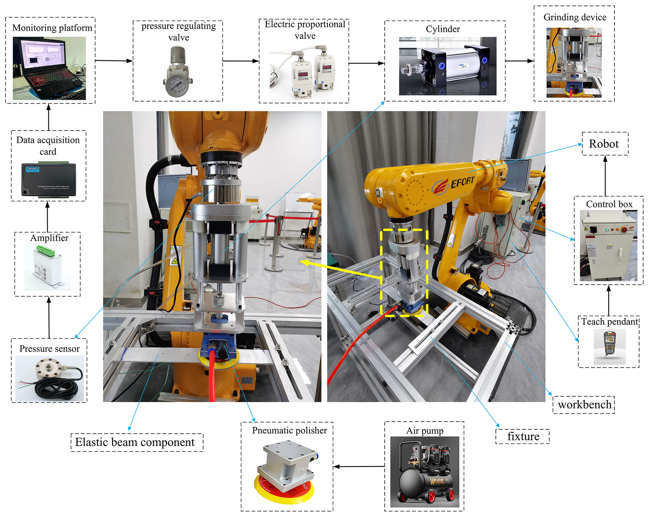
The experimental system of the ECGS is established for further verifying the designed grinding force adaptive controller, which is shown in Fig. 13. The industrial robot (ER10-1600, EFORT Ltd.) is used for the grinding experiment. The model of the pneumatic grinder is TG-6905, produced by Tai Guan. The model of the data acquisition card is USB-4704, produced by Advantech Co. The model of the cylinder is SC32-25S (buffer cylinder). The pressure sensor (DYLF-102, Bengbu Dayang Sensing System Engineering Co., Ltd.) is used for measuring grinding contact force. The upper end of the pneumatic servo grinding device is installed on the industrial robot through the coupling flange, and the lower end is in contact with the EBC. During the experiment, the grinding contact force was measured in real time by the pressure sensor of the pneumatic servo grinding device. The A/D conversion was realized through the data acquisition card, and then the data were collected and stored by the designed data collection and processing system in LABVIEW2020. The material of the EBC is aluminum alloy. Through adjusting the voltage of the solenoid servo valve to control the cylinder output, the grinding force adaptive controller is used for achieving the constant force control of the grinding force.
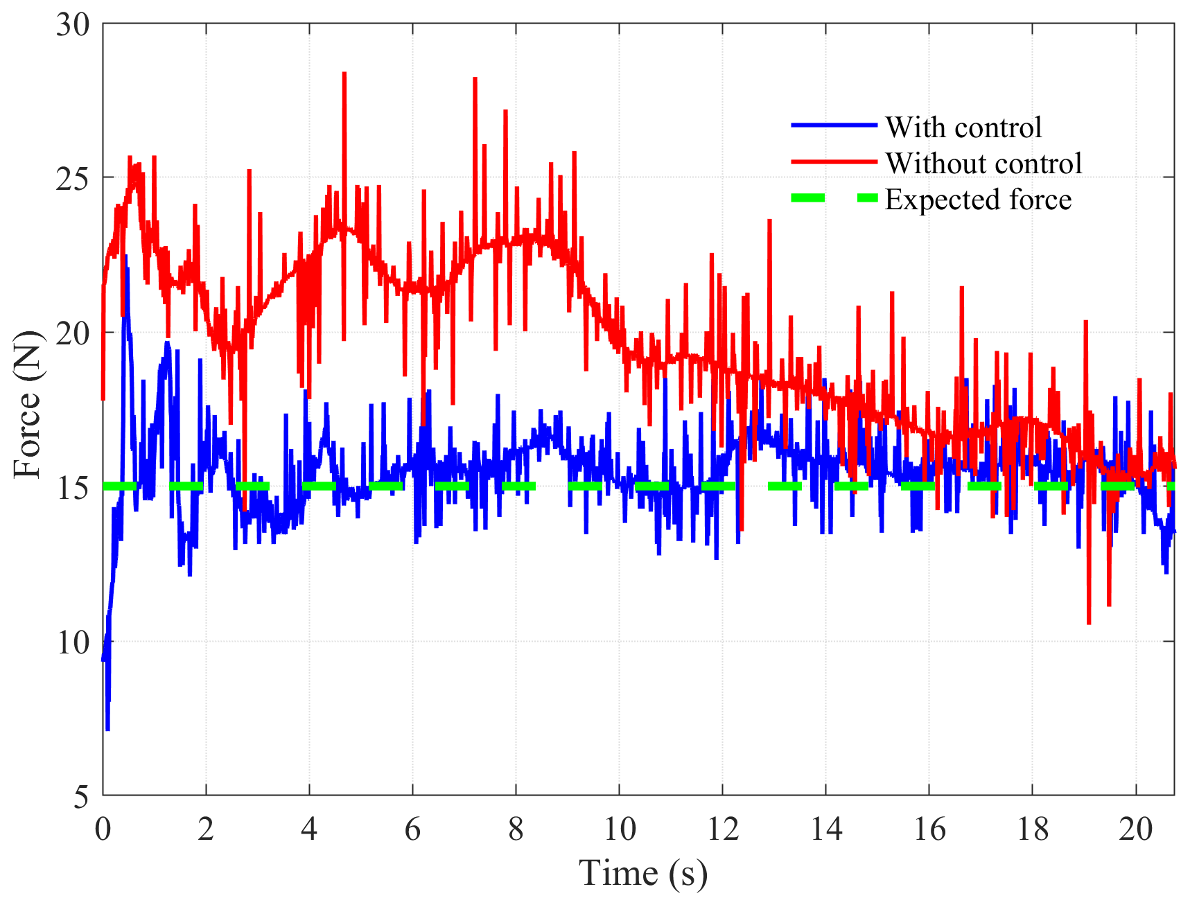
The grinding experiment parameters are set as follows: the robotic grinding path is along the workpiece surface, the industrial robot movement speed is 0.02 m s−1, the speed of the pneumatic polisher is 6000 r min−1 and the expected contact force during the grinding process is 15 N. Figure 14 shows the experimental results of the robot grinding for the EBC. It is seen that without the effect of the grinding force adaptive controller, the grinding contact force fluctuates significantly during the grinding of the EBC. Fortunately, the designed grinding force adaptive controller can restrain the grinding contact force fluctuation to a certain extent, which is conducive to ensuring the stability of the grinding contact force.
In this paper, the vibration coupling characteristics and grinding force control strategy of the ECGS are investigated, and the following conclusions can be obtained.
- i.
Based on the equivalent stiffness model of the EBC and the vibration displacement equation, the time-varying dynamic load characteristics of the EBC were characterized. On this basis, the dynamic coupling model of the ECGS is established, which can be used to directly reflect the coupling relationship between the vibration of the EBC and the grinding contact force.
- ii.
Based on the established rigid–flexible coupling dynamic model of the ECGS, the system dynamic simulation model is constructed. And the simulation results show that there is a coupling relationship between the elastic vibration and the grinding contact force, which should be considered in the grinding contact force control.
- iii.
A grinding force adaptive controller is designed under the elastic vibration coupling of the EBC. It is obvious from the virtual prototype co-simulation experiment results and the real prototype experiment results that the fluctuation of the grinding force can be effectively suppressed. The research results in this paper have guiding significance for the constant force control of the robot grinding system for the elastic components.
All the data in this paper can be obtained by request from the corresponding author.
YL proposed the research idea of this paper, LW and JJ carried out the theoretical modeling and experimental research. LW and JJ designed the control system. YL and LW completed the manuscript writing. EL put forward some constructive suggestions. YL, JJ and EL revised the paper.
The contact author has declared that none of the authors has any competing interests.
Publisher’s note: Copernicus Publications remains neutral with regard to jurisdictional claims made in the text, published maps, institutional affiliations, or any other geographical representation in this paper. While Copernicus Publications makes every effort to include appropriate place names, the final responsibility lies with the authors.
This research has been supported by the National Natural Science Foundation of China (grant no. 51805001), the National Key Research and Development Program of China (grant no. 2022YFD00150402), the University Natural Science Research Project of Anhui Province (grant nos. 2023AH030018 and 2023AH050931), and the Key Research and Development Program of Wuhu (grant nos. 2022yf57 and 2022jc25).
This paper was edited by Zi Bin and reviewed by two anonymous referees.
Chai, Y. Y., Song, Z. G., and Li, F.M.: Active aerothermoelastic flutter suppression of composite laminated panels with time-dependent boundaries, Compos. Struct., 179, 61–76, https://doi.org/10.1016/j.compstruct.2017.07.053, 2017.
Chen, F., Zhao, H., Li, D., Chen, L., Tan, C., and Ding, H.: Contact force control and vibration suppression in robotic polishing with a smart end effector, Robot. Com.-Int. Manuf., 57, 391–403, https://doi.org/10.1016/j.rcim.2018.12.019, 2019.
Dai, S., Li, S., Ji, W., Sun, Z., and Zhao, Y.: Force tracking control of grinding end effector based on backstepping plus PID, Industrial Robot-the Int. J. Robot. Res. Appl., 49, 34–46, https://doi.org/10.1108/ir-10-2020-0229, 2022.
Ding, B., Zhao, J., and Li, Y.: Design of a spatial constant-force end-effector for polishing/deburring operations, Int. J. Adv. Manuf. Tech., 116, 3507–3515, https://doi.org/10.1007/s00170-021-07579-1, 2021.
Ding, Y., Min, X., Fu, W., and Liang, Z.: Research and application on force control of industrial robot polishing concave curved surfaces, P. I. Mech. Eng. B-J. Eng., 233, 1674–1686, https://doi.org/10.1177/0954405418802309, 2019.
Dong, Y., Ren, T., Hu, K., Wu, D., and Chen, K.: Contact force detection and control for robotic polishing based on joint torque sensors, Int. J. Adv. Manuf. Tech., 107, 2745–2756, https://doi.org/10.1007/s00170-020-05162-8, 2020.
Du, H., Sun, Y., Feng, D., and Xu, J.: Automatic robotic polishing on titanium alloy parts with compliant force/position control, P. I. Mech. Eng. B-J. Eng., 229, 1180-1192, https://doi.org/10.1177/0954405414567518, 2015.
Huang, T., Sun, L. N., Wang, Z. H., Yu, X. Y., and Chen, G. D.: Hybrid force/position control method for robotic polishing based on passive compliance structure, Robot, 39, 776–794, https://doi.org/10.13973/j.cnki.robot.2017.0776, 2017.
Jia, Z., Lu, X., Yang, K., Sun, X., and Liang, S. Y.: Stability of micro-milling thin-walled part process, Int. J. Adv. Manuf. Tech., 112, 1529–1544, https://doi.org/10.1007/s00170-020-06509-x, 2021.
Jiang, X., Yang, N., Zhang, Y., and Gao, S.: An improved dynamics modeling during milling of the thin-walled parts based on magnetorheological damping fixture, Int. J. Adv. Manuf. Tech., 121, 2683–2698, https://doi.org/10.1007/s00170-022-09489-2, 2022.
Jin, X., Sun, Y. W., Guo, Q., and Guo, D. M.: 3D stability lobe considering the helix angle effect in thin-wall milling, Int. J. Adv. Manuf. Tech., 82, 2123–2136, https://doi.org/10.1007/s00170-015-7570-8, 2016.
Li, B. M., Zhao, B., and Li, Q.: Abrasives, Abrasive Tools and Grinding Techniques, Chemical Industry Press, Beijing, China, ISBN 9787122248855, 2016.
Liu, Y. F., Tang, D., and Ju, J. Y.: Electromechanical Coupling Dynamic and Vibration Control of Robotic Grinding System for Thin-Walled Workpiece, Actuators, 12, 37, https://doi.org/10.3390/act12010037, 2023.
Mohammad, A. E. K., Hong, J., and Wang, D.: Design of a force-controlled end-effector with low-inertia effect for robotic polishing using macro-mini robot approach, Robot. Com.-Int. Manuf., 49, 54–65, https://doi.org/10.1016/j.rcim.2017.05.011, 2018.
Mohammad, A. E. K., Hong, J., Wang, D., and Guan, Y.: Synergistic integrated design of an electrochemical mechanical polishing end-effector for robotic polishing applications, Robot. Com.-Int. Manuf., 55, 65–75, https://doi.org/10.1016/j.rcim.2018.07.005, 2019.
Qiu, Z.C., Wang, T. X., and Zhang, X. M.: Sliding mode predictive vibration control of a piezoelectric flexible plate, J. Intel. Mat. Syst. Str., 32, 65–81, https://doi.org/10.1177/1045389x20948597, 2021.
Sina, S. A. and Haddadpour, H.: Axial-torsional vibrations of rotating pretwisted thin walled composite beams, Int. J. Mech. Sci., 80, 93–101, https://doi.org/10.1016/j.ijmecsci.2013.12.018, 2014.
Rao, S. S.: Mechanical Vibration, 5th edn., Pearson Education Inc, New York, NY, USA, ISBN 9787302440581, 2011.
Song, H. C. and Song, J. B.: Precision Robotic Deburring Based on Force Control for Arbitrarily Shaped Workpiece Using CAD Model Matching, Int. J. Precis. Eng. Man., 14, 85–91, https://doi.org/10.1007/s12541-013-0013-2, 2013.
Tian, F., Li, Z., Lv, C., and Liu, G.: Polishing pressure investigations of robot automatic polishing on curved surfaces, Int. J. Adv. Manuf. Tech., 87, 639–646, https://doi.org/10.1007/s00170-016-8527-2, 2016a.
Tian, F., Lv, C., Li, Z., and Liu, G.: Modeling and control of robotic automatic polishing for curved surfaces, Cirp J. Manuf. Sci. Tec., 14, 55–64, https://doi.org/10.1016/j.cirpj.2016.05.010, 2016b.
Tressler, J. M., Clement, T., Kazerooni, H., and Lim, M.: Dynamic behavior of pneumatic systems for lower extremity extenders, 2002 IEEE International Conference on Robotics adn Automation, 11–15 May 2002, Washington, DC, United States, Institute of Electrical and Electronics Engineers, 3248–3253, https://doi.org/10.1109/ROBOT.2002.1013727, 2002.
Villagrossi, E., Pedrocchi, N., Beschi, M., and Tosatti, L. M.: A human mimicking control strategy for robotic deburring of hard materials, Int. J. Comp. Integ. M., 31, 869–880, https://doi.org/10.1080/0951192x.2018.1447688, 2018.
Wang, D., Fan, H., Xu, D., and Zhang, Y.: Research on Grinding Force of Ultrasonic Vibration-Assisted Grinding of C/SiC Composite Materials, Appl. Sci.-Basel, 12, 10352, https://doi.org/10.3390/app122010352, 2022.
Wang, J., Liang, F., Zhou, H., Yang, M., and Wang, Q.: Analysis of Position, Pose and Force Decoupling Characteristics of a 4-UPS/1-RPS Parallel Grinding Robot, Symmetry-Basel, 14, 825, https://doi.org/10.3390/sym14040825, 2022.
Wang, Q., Wang, W., Zheng, L., and Yun, C.: Force control-based vibration suppression in robotic grinding of large thin-wall shells, Robot. Com.-Int. Manuf., 67, 102031, https://doi.org/10.1016/j.rcim.2020.102031, 2021.
Wang, S. S., Jia, Z. Y., Lu, X. H., Zhang, H. X., Zhang, C., and Liang, S. Y.: Simultaneous optimization of fixture and cutting parameters of thin-walled workpieces based on particle swarm optimization algorithm, Simul.-T. Soc. Mod. Sim., 94, 67–76, https://doi.org/10.1177/0037549717713850, 2018.
Wang, X. and Qin, Z. M.: Nonlinear modal interactions in composite thin-walled beam structures with simultaneous 1 : 2 internal and 1 : 1 external resonances, Nonlinear Dynam., 86, 1381–1405, https://doi.org/10.1007/s11071-016-2970-3, 2016.
Xu, J. Z., Zheng, X. H., and Zhou, X.: Active and compliant control of the composite polishing robot, Electric Machines and Control, 23, 151–158, https://doi.org/10.15938/j.emc.2019.12.019, 2019.
Xu, X., Zhu, D., Zhang, H., Yan, S., and Ding, H.: Application of novel force control strategies to enhance robotic abrasive belt grinding quality of aero-engine blades, Chinese J. Aeronaut., 32, 2368–2382, https://doi.org/10.1016/j.cja.2019.01.023, 2019.
Xu, X., Chen, W., Zhu, D., Yan, S., and Ding, H.: Hybrid active/passive force control strategy for grinding marks suppression and profile accuracy enhancement in robotic belt grinding of turbine blade, Robot. Com.-Int. Manuf., 67, 102047, https://doi.org/10.1016/j.rcim.2020.102047, 2021.
Yin, C. and Zhou, Z.: Concise and Quick Reference Manual of Machining Process, Chemical Industry Press, Beijing, China, ISBN 978-7-122-25373-6, 2017.
Zhang, D., Li, C., and Jia, D.: Investigation into Engineering Ceramics Grinding Mechanism and the Influential Factors of the Grinding Force, School of Mechanical Engineering, Qingdao Technological University, Int. J. Ctrl. Autom., 7, 19–34, https://doi.org/10.14257/ijca.2014.7.4.03, 2014.
Zhang, H., Chen, H., Xi, N., Zhang, G., and He, J.: On-line path generation for robotic deburring of cast aluminum wheels, IEEE/RSJ international conference on intelligent robots and systems, 9–15 October 2006, Beijing, China, Institute of Electrical and Electronic Engineers, 2400–2405, https://doi.org/10.1109/IROS.2006.281679, 2006.
Zhang, H., Li, L., Zhao, J., Zhao, J., Liu, S., and Wu, J.: Design and implementation of hybrid force/position control for robot automation grinding aviation blade based on fuzzy PID, Int. J. Adv. Manuf. Tech., 107, 1741–1754, https://doi.org/10.1007/s00170-020-05061-y, 2020.
Zhang, T., Yu, Y., Yang, L. X., Xiao, M., and Chen, S. Y.: Robot Grinding System Trajectory Compensation Based on Co-Kriging Method and Constant-Force Control Based on Adaptive Iterative Algorithm, Int. J. Precis. Eng. Man., 21, 1637–1651, https://doi.org/10.1007/s12541-020-00367-z, 2020a.
Zhang, T., Xiao, M., Zou, Y., and Xiao, J.: Robotic constant-force grinding control with a press-and-release model and model-based reinforcement learning, Int. J. Adv. Manuf. Tech., 106, 589–602, https://doi.org/10.1007/s00170-019-04614-0, 2020b.
Zhao, P. and Shi, Y.: Composite Adaptive Control of Belt Polishing Force for Aero-engine Blade, Chin. J. Mech. Eng., 26, 988–996, https://doi.org/10.3901/cjme.2013.05.988, 2013.
Zhou, H., Ma, S., Wang, G., Deng, Y., and Liu, Z.: A hybrid control strategy for grinding and polishing robot based on adaptive impedance control, Adv. Mech. Eng., 13, 16878140211004034, https://doi.org/10.1177/16878140211004034, 2021.