the Creative Commons Attribution 4.0 License.
the Creative Commons Attribution 4.0 License.
 | 20 Feb 2024
Kinematic analysis and bearing capacity optimization of fully decoupled two-rotation mechanisms
Sen Wang
Xueyan Han
Haoran Li
Hongyu Xu
Shihua Li
The existing vehicle durability test platform has low accuracy in reproducing the road spectrum and cannot meet the demand for high-accuracy road spectrum reproduction. In order to meet the need for high accuracy in road spectrum reproduction of vehicle durability tests, this paper is based on an analysis of the factors affecting the accuracy of the test platform. From the perspective of mechanism innovation, a fully decoupled two-rotation parallel mechanism with large load-bearing capacity for vehicle durability testing is proposed in this paper. A new solution is provided to improve the road spectrum reproduction accuracy of the test platform. Based on the requirement of reproduction accuracy of a real road spectrum, inverse kinematics, velocity Jacobians, and workspaces of mechanisms are analyzed. The inverse kinematics and velocity Jacobian analysis of parallel mechanisms can lay a research foundation for the subsequent calculation of load-bearing capacity indexes. The design of the parallel mechanism is based on the performance requirements of large load capacity and complete decoupling. A new index for evaluating the global average carrying capacity of a mechanism is proposed. Based on this index and the atlas method, the dimensional parameters of the mechanism have been optimized. A finite-element simulation study is carried out, and it is proved that the optimized fully decoupled two-rotation parallel mechanism can satisfy the bearing capacity requirements of the platform test. The large load capacity and fully decoupled mechanism proposed in the research work of this paper can improve the road spectrum reproduction accuracy of the vehicle durability test platform and has good application prospects in the field of vehicle durability tests.
- Article
(1605 KB) - Full-text XML
- BibTeX
- EndNote


A vehicle durability test bench is the main equipment used for indoor durability testing, and the realization of high-precision road spectrum reproduction is a research hotspot around the world. Although China is a big vehicle manufacturing country, we are still not able to break through the technical bottleneck of high-precision road spectrum reproduction in original vehicle durability test benches. Made in China 2025 states clearly that the innovative design of high-end mechanical equipment is the key direction of national strategic development. The development of a high-precision vehicle fatigue durability test bench with independent intellectual property rights is a key technology that is extremely challenging and that needs to be solved urgently. Therefore, it is of great significance to develop a high-precision vehicle durability test bench. Many scholars and vehicle companies have carried out studies on vehicle durability test benches. The British Salvo company developed four-channel and six-channel road simulation systems which are mainly used to test the bodies and chassis of vehicles (Zhang et al., 2015). Instron developed a road simulation test system for light or heavy vehicles (Mohajer et al., 2015) that was used for vehicle fatigue durability tests, comfort tests, NVH (noise, vibration, and harshness), and other common vehicle tests. Six-channel and eight-channel wheel-coupling road simulation test systems have been successfully developed (Gao, 2016) in China. The American Moog company developed a four-column road simulation test bench for chassis and suspension testing (Gao et al., 2017). In 1962, the world's first wheel-coupled road simulation test bench was developed by the American MTS company (Wang, 2018). The principle of the bench road simulation test that summarized the key technologies affecting bench tests was introduced (Gong and Yao, 2018). The road load spectrum was put as the driving signal into the wheel-coupled vehicle durability test bench to accurately reproduce the road spectrum (Xiang et al., 2019). Ju et al. (2021) carried out fatigue durability tests of vehicle cabs by building a CAE (computer-aided engineering) simulation model of the vehicle test bench and combining the load spectrum signals collected from the actual vehicle road tests. The successful development of the abovementioned wheel-coupling road simulation test bench has greatly shortened the time for high-precision wheel-coupling durability testing and improved the lives of vehicles. So far, most of the vehicle durability test benches have adopted a four-column mechanical structure. They can only provide the road spectrum in the vertical direction and can at most restore 70 % of the road conditions. Moreover, the real road spectrum in the pitch and roll directions is ignored, which results in low road spectrum reproduction accuracy. It is necessary to realize the excitation in both the pitch and roll directions from the design of the test equipment.
Due to the unique advantages of compact structure, strong bearing capacity, small cumulative error, and high precision, parallel mechanisms are increasingly favored in engineering applications (Li et al., 2019). Under high-frequency conditions, the control difficulty will increase because of the strong coupled characteristic of parallel mechanisms and the complexity of the road spectrum. The decoupled mechanism cannot meet the requirements of the road spectrum reproduction accuracy. The decoupling mechanism has the advantages of simple control and high output precision. To date, many scholars have done a lot of work on the design and analysis of decoupled parallel mechanisms (Tian et al., 2019; Zhang et al., 2020; Qu et al., 2021; Wu et al., 2021).
A 4 degree of freedom (DOF) decoupled 3T1R parallel mechanism was synthesized based on topological decoupling criteria (Hang et al., 2004). A basic principle of topology decoupling mechanism structure synthesis and a 3-DOF decoupled mechanism was proposed (Jin and Yang, 2004). The three types of 2- to 4-DOF decoupled parallel mechanisms were synthesized based on geometric methods (Kong and Gosselin, 2004). A faster isotropic 3T parallel mechanism was synthesized (Briot and Bonev, 2009). A two-rotation decoupling parallel mechanism was synthesized based on screw theory (Zeng and Huang, 2011). A class of 2R fully decoupled parallel mechanisms was synthesized based on screw theory (Cai et al., 2012). A class of 2T2R 4-DOF fully decoupled parallel mechanisms was synthesized based on the concept of hybrid mechanisms and the theory of reciprocal screws (Zhang and Wu, 2013). Various 3R1T decoupled parallel mechanisms were synthesized based on screw theory (Chen et al., 2016). Various new types of mechanisms were designed using the principle of structural decoupling (Shen et al., 2016). Various 3-DOF generalized decoupled parallel mechanisms were synthesized (Zeng et al., 2017). A configuration synthesis method for 3T2R fully isotropic hybrid mechanisms was proposed based on GF (a method of mechanism configuration synthesis) set theory (Cao et al., 2018). A system method for fully decoupled design of parallel manipulators was proposed through geometric reasoning of projected motion (Kuo and Dai, 2021).
However, the decoupled parallel mechanisms have a poor bearing capacity and cannot be better applied to vehicle durability tests. In this paper, according to the demand of high-precision road spectrum reproduction of vehicles, a fully decoupled two-rotation parallel mechanism with a large bearing capacity for vehicle durability tests is proposed. A new solution is provided for the development of a high-precision vehicle durability test bench. The decoupled characteristics, degrees of freedom, inverse kinematics, and velocity Jacobians of the mechanism are analyzed first. Then, a new index to evaluate the average carrying capacity of the mechanism is proposed. This index can accurately evaluate the load-bearing capacity of parallel mechanisms, laying a research foundation for subsequent mechanism optimization design. Finally, the optimal design of the two-rotation mechanism dimensional parameters is carried out, and the bearing capacity of the decoupled mechanism is optimized. The research fills the gap of the large load-bearing fully decoupled parallel mechanism configuration. It provides a theoretical foundation for the application of the high-precision vehicle durability test bench mechanism in the field of vehicle testing.
2.1 Mechanism design indexes
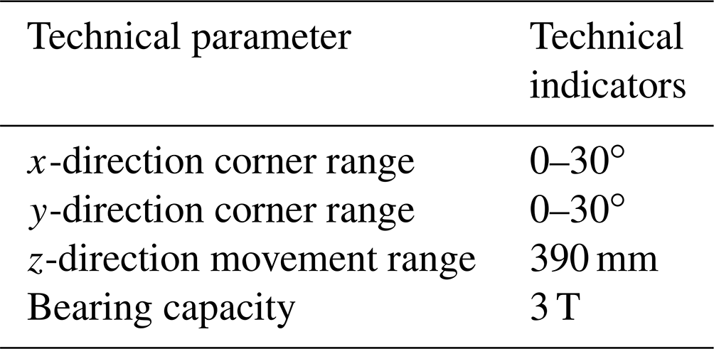
An on-site road test of vehicles mainly includes test items such as highways, mountain roads, expressways, non-paved roads, and durable roads. There are significant differences in vehicle operation under different road conditions, mainly in the vehicle's attitude of heave, pitch, and roll. In order to truly reproduce the road spectrum at the wheel of the vehicle, it is necessary to accurately simulate the road spectrum in the three directions of pitch, roll, and vertical movement. The maximum climbing slope of the vehicle is an important index to evaluate the climbing performance of the vehicle. At present, the maximum climbing slope of most cars is about 20∘, and some off-road vehicles have a maximum climbing slope of 30∘. In order to meet the climbing durability test requirements of most vehicles, it is determined that the pitch-and-roll angle range of the vehicle climbing durability test is not less than 30∘. Based on the moving range and the carrying capacity of the existing wheel-coupling test bench, the moving range and carrying capacity of the test bench in this paper are set to 390 mm and 3 T, respectively.
Determine the technical indexes of the vehicle durability test bench based on the actual operating conditions of the vehicle. The specific technical indexes of the vehicle durability test bench are shown in Table 1. This paper conducts relevant research on the vehicle durability test bench based on these technical indexes.
Table 1Technical indexes of the vehicle durability test bench.
2.2 Design scheme of the vehicle durability test bench
In order to meet the needs of vehicle fatigue durability tests, from the perspective of mechanical innovation design, a vehicle durability test platform with a simple structure, higher road spectrum reproduction accuracy, and easy control is proposed. This paper reduces the coupling of the mechanism based on the realization that the displacement and the rotation angle can be applied separately. The idea of using a redundant drive mode to increase the mechanism's carrying capacity by constructing a closed-loop unit, a fully decoupled mechanism with a large bearing capacity, is proposed. It can not only improve the road spectrum reproduction accuracy, but also increase the bearing capacity of the decoupling mechanism. In order to accurately realize the pitch, roll, and bumps of the car, the vehicle durability test bench should have the type of degrees of freedom to match. Therefore, the design scheme of this paper adopts a series-parallel mechanism with a large bearing capacity and fully decoupled 3 degrees of freedom as the basic configuration of the vehicle durability test bench.
2.3 Mechanism configuration design
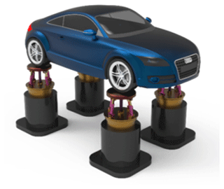
In this paper, a new type of fully decoupled 2UPR–2RPU–RR (where U is the hook hinge, P is the moving pair, and R is the rotating pair) parallel mechanism with a large bearing capacity is proposed. It is mainly composed of a moving platform, a fixed platform, and five branch chains connecting the two platforms. The mechanism provides 2 degrees of freedom of pitch and roll for each wheel in the vehicle. The mechanism is connected in series with the actuating cylinder that provides the vertical path spectrum to form a series-parallel mechanism. It can accurately reproduce the road excitation under different road conditions, and the road spectrum of the four wheels is independently controlled. As shown in Fig. 1, the vehicle durability test bench adopts the four-corner configuration in the actual test process, as shown in Fig. 2. The mechanical part includes four sets of corners that load the four tires of the tested vehicle. Each set of corners can apply vertical translation and pitch tilt rotation to one wheel independently. The 3 degrees of freedom are completely decoupled, the four corners can be loaded at the same time, and the simultaneous loading of 12 degrees of freedom can be achieved.
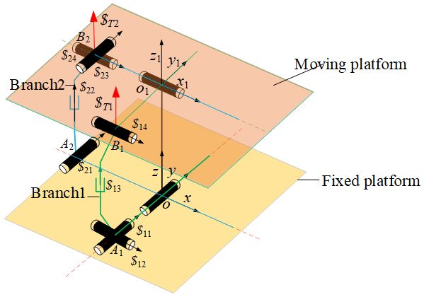
According to the complete decoupling criterion of the two-rotation parallel mechanism with a large bearing capacity proposed by our research group (Wang et al., 2021), constructing proper-constraint branches and basic decoupling branches, Branch 1 is the UPR structure. Branch 2 is the RPU structure. The proper-constraint branch chain is an RR structure. The two axes x and y of the kinematic pair of the proper-constraint branch chain are the output motion axes of the mechanism. Branch chain 1 controls the rotational freedom of the moving platform around the x axis. Branch chain 2 controls the rotational freedom of the moving platform around the y axis. The revolute pairs which are directly connected to the moving platform of branch chain 1 and the just-constrained RR branch are coaxial. The revolute pairs which are directly connected to the fixed platform of branch chain 2 and the just-constrained RR branch are coaxial (shown in Fig. 3).
The technical indexes of the vehicle durability test bench are presented in Table 1. The platform has a load-bearing capacity of 3 T, and the parallel mechanism under a single wheel needs to bear a load of 7500 N. The 2 rotational degrees of freedom of the non-redundant UPR–RPU–RR parallel mechanism are completely decoupled, with a high output accuracy. However, the area without branch chain support of the non-redundant UPR–RPU–RR parallel mechanism has an extremely weak load-bearing capacity and cannot be used for dynamic testing of vehicle durability. Therefore, it is necessary to add redundant branches in order for the mechanism to have a strong load-bearing capacity and output accuracy.
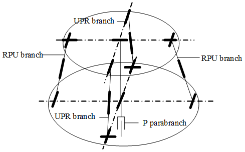
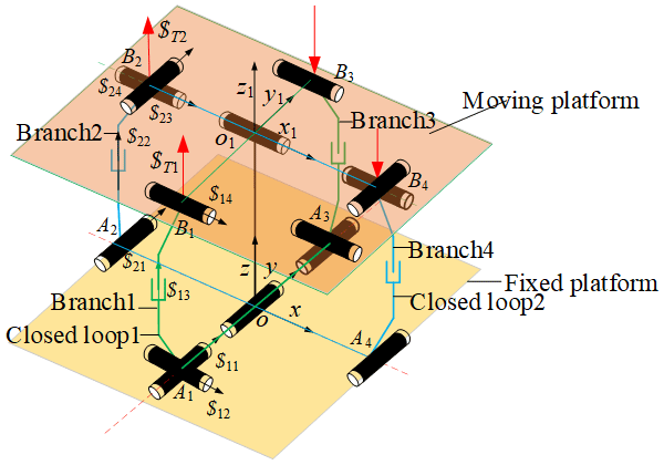
In order to make the mechanism have a large bearing capacity, the redundant branch chain 3 and the redundant branch chain 4 of the loop are constructed as shown in Fig. 4. Branch 1 and branch 3 have the same UPR structure. Branch 2 and branch 4 have the same RPU structure. The revolute pairs which are directly connected to the fixed platform of branch chain 3 and the just-constrained RR branch are coaxial. The revolute pairs which are directly connected to the fixed platform of branch chain 4 and the just-constrained RR branch are coaxial. Branch 1 and branch 3 form the closed loop 1. Branch chain 2 and branch chain 4 form the closed loop 2. Each closed loop consists of the same structure of a basic decoupling branch chain and a redundant driving branch chain. The structure of the closed loop does not change the decoupling characteristics of the mechanism but improves the bearing capacity of the mechanism. Branch 3 and branch 1 are equal in magnitude and opposite in direction. The drive displacements of the redundant drives of branch 4 and branch 2 are equal in magnitude and opposite in direction.
2.4 Verification of the mechanism decoupling characteristics
Zhou et al. (2015) proposed that the force-transferring screw means that, when the input joint is locked, the reciprocal product of all the other kinematic spinors except the driving screw in the branch is zero. Such a screw represents the generalized transfer force in the branch chain that transfers the motion and force from the input joint to the moving platform. Therefore, the decoupled characteristics of the parallel mechanism are defined based on the transfer force screw theory as follows: the transfer force screw of the branch can only do work on the output degrees of freedom controlled by the branch. In this paper, the force transmission screw $T1 of branch chain 1 of the two-rotation parallel mechanism is always coplanar with the y axis and is different from the x axis. Therefore, it can only output the rotational degree of freedom in the x-axis direction. The force transmission screw $T2 of branch chain 2 is always coplanar with the x axis and is different from the y axis. Therefore, the rotational degrees of freedom in the y-axis direction can be outputted. This proves that the 2 rotational degrees of freedom of the mechanism are fully decoupled.
It can be known from screw theory that the mechanism has a total of 12 constraint screws. Among them, four screws are linearly independent, so the mechanism has eight redundant constraints; i.e., v=8. The mechanism has no passive degrees of freedom: ς=0. The number of mechanism components is 11, the number of kinematic pairs is 14, and the total number of degrees of freedom of the mechanism's kinematic pairs is 18. Applying the modified G–K formula, the degrees of freedom of the mechanism is
To sum up, the two-rotation over-constrained 2UPR–RR–2RPU parallel mechanism has 2 degrees of freedom, i.e., rotational degrees of freedom around the x axis and y axis. The number of mechanism driving pairs is 4, so this is a redundant parallel mechanism.
3.1 Inverse solution of the mechanism
The posture of the moving platform can be represented by the intermediate constrained branch. First, the fixed coordinate system o rotates the angle α around the y axis. Then the new coordinate system rotates the angle β around the x axis to obtain the moving coordinate system o1. The rotation transformation matrix can be expressed as
The origin of the moving platform coordinate system in the fixed coordinate system is expressed as
d represents the distance between point o and point o1 in Fig. 4.
The midpoint of each kinematic pair on the fixed platform is expressed in the fixed coordinate system as
a1 represents the distance between point o and point Ai.
The midpoint of each kinematic pair on the moving platform is expressed in the moving coordinate system as
b1 represents the distance between point o1 and point Bi.
The midpoint of each kinematic pair in the moving coordinate system is expressed in the fixed coordinate system as
The direction vector of each branch along the driving pair direction is
The inverse solution of the mechanism means that the length of each drive branch is
3.2 Solution of the mechanism velocity Jacobian matrix
Take the derivative of both ends of Eq. (12):
where rei is the vector diameter from o1 to Bi, and ω is the rotational angular velocity of the moving platform.
rsi represents the unit direction vector of the driving rods of the two-rotation mechanism, and li represents the length of branch i of the mechanism.
The driving speed of the two-rotation mechanisms is
J represents the mapping relationship between the driving speed and the moving platform speed.
4.1 The new index of the average carrying capacity of the whole region
The bearing capacity index of the parallel mechanism reflects the ability of the mechanism to balance external forces. According to Yuan et al. (2020), the relationship between the driving force f and the output force or torque vector F is as follows:
where G is the force Jacobian matrix of the mechanism.
The force Jacobian matrix and the velocity Jacobian matrix of the mechanism have the following dual relationship:
In this formula, J is the inverse Jacobian matrix of the mechanism, and J−1 is the positive Jacobian matrix of the mechanism. The Jacobian matrix J is a 4 × 6 matrix, not a square matrix, and it has a generalized inverse. When the module length of the driving force f is 1, the extreme value of the module of the force or torque vector F is outputted.
To solve this extreme value, the following Lagrangian equation is constructed:
where λF is the Lagrangian multiplier. The necessary condition for the conditional extremum is
which is
It can be seen from the above formula that λF is the eigenvalue of the matrix GTG. The square of the modulus of F can be written as
The extreme value of F is the square of the eigenvalues of the matrix GTG, which is
and represent the maximum and minimum eigenvalues, respectively, of the matrix GTG. and represent the largest and smallest singular values, respectively, of the inverse Jacobian matrix. ∥Fmax∥ and ∥Fmin∥ are the maximum and minimum load capacities at the end of the mechanism when the module length of the driving force is 1. This singular value is the most widely used index for evaluating the load-carrying capacity of parallel mechanisms. However, this indicator can only reflect the independently changing situation of the maximum and minimum carrying capacities, respectively, of the mechanism. When the maximum and minimum bearing capacity evaluation indicators change inconsistently, it is impossible to accurately evaluate the bearing capacity of the mechanism. It cannot comprehensively evaluate the average load-bearing situation of parallel mechanisms using one evaluation index. The evaluation index of the average bearing capacity can accurately evaluate the distribution of the average bearing capacity of parallel mechanisms in the entire workspace. Accurately evaluating the average bearing capacity of mechanisms has important research significance for subsequent optimization of mechanism-bearing capacities.
The mean of the extreme values of F can be expressed as
The average bearing capacity index Fave proposed in this paper represents the average bearing capacity of the mechanism in a certain pose.
In order to accurately evaluate the carrying capacity of the mechanism in its workspace, a global average carrying capacity index is proposed. Take the average value of the average load-bearing capacity of the mechanism in one of the above positions within the workspace W of the mechanism. This indicator can comprehensively reflect the change in the mechanism's carrying capacity. The expression of the mechanism's global average carrying capacity index is
W represents the workspace of the mechanism. The larger the average carrying capacity indicators in the global area are, the higher the average carrying capacity of the mechanism is.
4.2 Bearing capacity analysis of the mechanism
When the global average bearing capacity index is used to evaluate the bearing capacity of the mechanism, the dimension parameters of the mechanism need to be dimensionless. The dimension parameters a1, b1, and d of the mechanism need to be dimensionless, and parameter D can be expressed as
The dimensionless parameters a, b, and c of the three parameters a1, b1, and d can be expressed as
Based on the dimensionless parameters, take advantage of MATLAB software®: the bearing capacity of the two-rotation parallel mechanism is analyzed and optimized.
The motion range of the moving platform is set to (0∘, 30∘). Then, the average bearing capacity index of the moving platform is calculated in each posture. The surface diagram of the global average bearing capacity which changes with the posture of the moving platform of the non-redundant mechanism UPR–RPU–RR is obtained, as shown in Fig. 5.
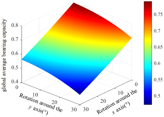
Figure 5Surface diagram of the global average bearing capacity index of non-redundant mechanisms.
By analyzing Fig. 5, it can be shown that the global average bearing capacities of the mechanism change with the posture and position of the moving platform. The closer it is to the initial position, the better the global average bearing capacity of the mechanism is. The larger the rotation range is, the worse the global average bearing capacity of the mechanism is. In order to make the mechanism have a better bearing capacity according to the index range of the abovementioned global average bearing capacity performance index map, give the ζave index a high value and give the performance index value a range of ζave>0.8, which shows that the mechanism has a good carrying capacity.
4.3 Optimization of the bearing capacity of the mechanism by adding redundant drives
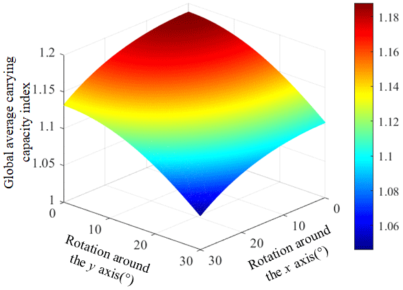
The non-redundant mechanism UPR–RPU–RR can realize the fully decoupled 2 rotational degrees of freedom, which meets the requirements of road spectrum reproduction accuracy. However, the bearing capacity of the decoupled mechanism is weak. It cannot bear the weight of the entire vehicle, which is difficult to apply for vehicle fatigue durability tests. On the basis of the non-redundant mechanism, the redundant drives with the same displacement as and opposite direction to the basic decoupled branch drives are added, and based on Eq. (28), the carrying capacity index of the moving platform in each pose is calculated. Surface diagrams of the global average bearing capacity of the redundant mechanism UPR–RPU–RR are shown in Fig. 6.
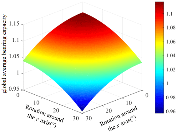
Figure 6Surface diagram of the global average bearing capacity index of the redundant mechanism.
By analyzing Fig. 6, it can be shown that, under the condition that the sizes of the moving platform and the fixed platform of the mechanism remain unchanged, for the moving platform in different poses, the global average carrying capacity of the redundant mechanism presents different values. The closer it is to the initial position, the better the global average bearing capacity of the mechanism is. The larger the rotation range is, the worse the global maximum and minimum bearing capacity of the mechanism is. By adding redundant drives, the maximum value of the redundant mechanism's global average carrying capacity is increased by 31 %, and the minimum value is increased by 48 %. The above results demonstrate that the load-bearing capacity of the mechanism can be significantly improved by adding redundant drives.
4.4 Mechanism dimension parameter optimization
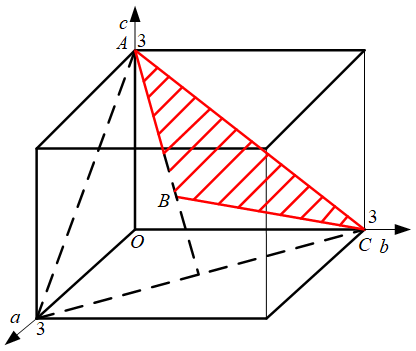
In order to achieve the correct assembly relationship and motion capability of the redundant mechanism, the dimensionless size parameters a, b, and c of the parallel durability test bench must meet the following conditions.
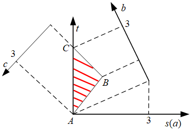
According to Eq. (32), the parameter design space of the mechanism can be established as the triangle ABC in Fig. 7 through the following linear transformation.
Solve Eq. (33) to obtain Eq. (34).
Then the parameter design space of the mechanism can be transformed into the triangle ABC as shown in Fig. 8.
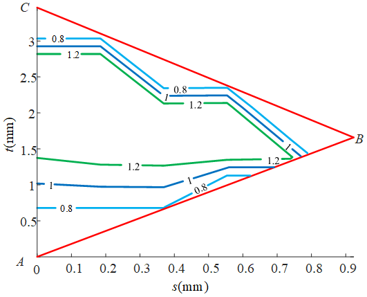
Through the theoretical calculation, the performance diagram of the global average bearing capacity in the two-rotation parallel mechanism can be obtained as shown in Fig. 9. The area where ζave = 1.2 in the performance diagram is defined as a good performance area. In order to obtain a good bearing capacity, the parameters of the good performance area are selected as the optimization parameters of the mechanism, such as s = 0.7 or t = 1.6. The dimensionless parameters of the optimized mechanism can be obtained as a = 0.7, b = 1.04, and c = 1.26. The size parameters of the mechanism are restored according to the dimensionless proportional coefficient. Then the final optimized actual size parameters are obtained. The distance between the center of each kinematic pair of the moving platform and the center of the moving platform is r1 = 300 mm. The distance between the center of each kinematic pair of the fixed platform and the center of the fixed platform is r2 = 445.7 mm. The initial height of the mechanism moving platform is z = 540 mm. According to the analysis of the carrying capacity index proposed in this paper, the maximum value of the global average carrying capacity of the mechanism is 36.5 % higher than that of the mechanism without redundant drives and size optimization. As shown in Fig. 10, this demonstrates that the load-carrying capacity of the mechanism can be significantly improved by sizing optimization and adding redundant drives.
5.1 Verification of the fully decoupled mechanism workspace
According to the size parameters of the optimized mechanism, the parameters of the fully decoupled 2UPR–2RPU–RR+P mechanism are set as follows. The distance between the center of each kinematic pair of the moving platform and the center of the moving platform is r1 = 300 mm. The distance between the center of each kinematic pair of the fixed platform and the center of the fixed platform is r2 = 445.7 mm. The initial height of the mechanism's moving platform is z = 540 mm. The variation ranges of the driving branches of the two-rotation mechanism are 228–323 and 190–323 mm, respectively. The variation range of the driving branch of the 1-DOF motion mechanism is 0–390 mm. According to the above parameters, the workspace of the mechanism is calculated by using MATLAB software®, as shown in Fig. 11.
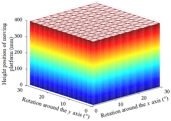
Figure 11 shows a three-dimensional view of the mechanism's workspace. Since the mechanism is completely decoupled, there is no singular position within the scope of the workspace, so the overall workspace of the mechanism approximates the shape of a cuboid. The rotation angle range of the mechanism around x and y is 0–30∘. The range of motion in the z direction is 0–390 mm. It meets the performance index requirements of the mechanism and verifies the correctness of the motion range of the mechanism.
5.2 Verification of the bearing capacity of the fully decoupled mechanism
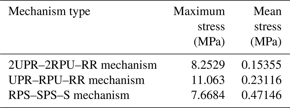
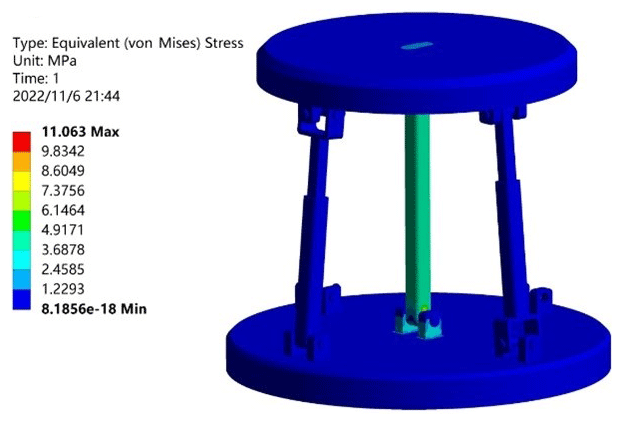
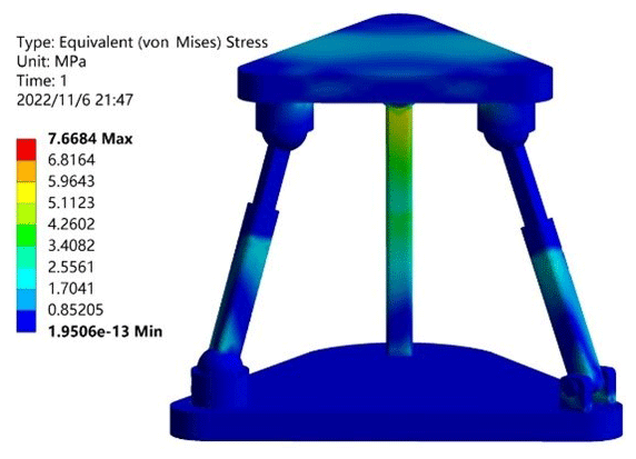
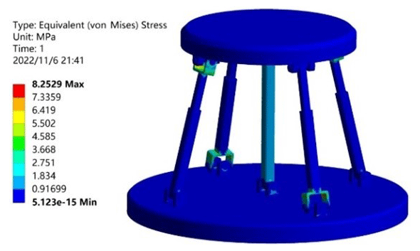
In order to verify that the two-rotation loop-decoupling parallel mechanism proposed in this paper had large load-bearing characteristics, the material was given as structural steel. In the initial configuration, a vertical downward load of 7500 N was used as the boundary condition. The analysis was carried out by the finite-element analysis software from ANSYS®. The load capacity of the optimized 2UPR–2RPU–RR closed-loop decoupling mechanism, the pre-optimized UPR–RPU–RR decoupled mechanism, and the RPS–SPS–S coupled parallel mechanism were compared. As shown in Table 2, the stress cloud diagram of the UPR–RPU–RR decoupling mechanism is shown in Fig. 12. The stress cloud diagram of the RPS–SPS–S coupled parallel mechanism is shown in Fig. 13. The stress cloud diagram of the 2UPR–2RPU–RR parallel mechanism after size optimization is shown in Fig. 14. The three configurations have the same cross-sectional area and boundary conditions. The simulation shows that the maximum stress of the two-rotation loop-decoupled parallel mechanism is slightly larger than the maximum stress of the RPS–SPS–S coupled parallel mechanism. However, the average stress of the two-rotation loop-decoupled parallel mechanism is much smaller than the average stress of the RPS–SPS–S coupled parallel mechanism, which is only 32 % of the coupled mechanism. The UPR–RPU–RR decoupled mechanism increases the average load capacity by 35 % after adding a closed-loop unit and optimizing the dimensions. Compared with the theoretical value calculated by MATLAB, the error is 1.5 %. This verifies the correctness of the global average carrying capacity index proposed in this paper. The optimized two-rotation decoupling parallel mechanism has a high bearing capacity, and it meets the index requirements of the bearing capacity of the vehicle durability test bench.
Table 2Comparison table of the carrying capacities of the different mechanisms.
From the above analysis, it can be seen that the optimized parallel mechanism has improved its load-bearing capacity without changing the workspace and decoupled characteristics of the mechanism, which can meet the requirements of vehicle durability testing indexes.
-
In this paper, a new two-rotation fully decoupled parallel mechanism with a large bearing capacity is proposed.
-
Based on the actual operating conditions of the vehicle, the bearing capacity index of the vehicle durability test bench is determined. The decoupled characteristics of the mechanism are analyzed. The degree of freedom of the mechanism is solved based on screw theory. The kinematic inverse model and the inverse Jacobian matrix of the mechanism are established. Based on the inverse Jacobian matrix, a new index for evaluating the average carrying capacity of the mechanism in the global area is proposed.
-
Based on the new index of the global average carrying capacity, by adding redundant drive and size optimization, the bearing capacity of the mechanism is optimized. The load-carrying capacity of the optimized mechanism is increased by 36.5 %. It is verified by a finite-element simulation where the optimized mechanism satisfies the requirements of the bearing capacity of the vehicle durability test bench and justifies the correctness of the proposed mechanism.
The code and data included in this article can be made available by the corresponding author upon reasonable request. Please note that the codes and data are confidential and cannot be made publicly available with respect to future applications.
SL was in charge of the whole study. SW wrote the manuscript. XH discussed and read the manuscript. HL assisted with the analysis and validation. HX was responsible for the grammar check and error correction of the paper. All the authors read and approved the final manuscript.
The contact author has declared that none of the authors has any competing interests.
Publisher's note: Copernicus Publications remains neutral with regard to jurisdictional claims made in the text, published maps, institutional affiliations, or any other geographical representation in this paper. While Copernicus Publications makes every effort to include appropriate place names, the final responsibility lies with the authors.
This work was funded by the National Natural Science Foundation of China under grant no. 52275032 and a key project of the Hebei Natural Science Foundation under grant no. E2022203077.
This research has been supported by the National Natural Science Foundation of China (grant no. 52275032), the key project of Hebei Natural Science Foundation (grant no. E2022203077), and the key research and development plan of Hebei Province (grant no. 202230808010057).
This paper was edited by Daniel Condurache and reviewed by three anonymous referees.
Briot, S. and Bonev, I.: Pantopteron: a new fully decoupled 3-DOF translational parallel robot for pick-and-place applications, J. Mech. Robot., 1, 795–810, https://doi.org/10.1115/1.3046125, 2009.
Cai, W. L., Xiong, T., and Yin, Z. P.: Type synthesis of a rotational decoupled leveling mechanism based on screw theory, China Mechanical Engineering, 23, 2213–2242, https://doi.org/10.3969/j.issn.1004-132X.2012.18.015, 2012.
Cao, Y., Zhou, R., Qin, Y. L., Ge, S. Y., and Ding, R.: Structural synthesis of fully-isotropic five degree-of-freedom hybrid kinematic mechanisms, J. Eng. Mech., 54, 29–37, https://doi.org/10.3901/JME.2018.05.029, 2018.
Chen, H., Qin, Y. L., and Cao, Y.: Type synthesis of three-rotational and one-translational decoupling parallel mechanisms, China Mechanical Engineering, 27, 1243–1250, https://doi.org/10.3969/j.issn.1004-132X.2016.09.017, 2016.
Gao, L. S.: Analysis of road simulation test system, Automotive Practical Technology, 9, 188–190, https://doi.org/10.16638/j.cnki.1671-7988.2016.09.063, 2016 (in Chinese).
Gao, Y., Wang. G., and Han, J.: The Study on Fatigue Test of Cab Assembly Based on 4-Channel Road Simulation Bench, SAE Technical Paper 2017-01-0328, https://doi.org/10.4271/2017-01-0328, 2017.
Gong, H. B. and Yao, L.: Review on the development of indoor bench road simulation test technology, Chinese J. Automot. Eng., 8, 72–78, https://doi.org/10.3969/j.issn.2095-1469.2018.01.12, 2018.
Hang, L. B., Wang, Y., and Yang, T. L.: Analysis of a new type 3 translations 1 rotation decoupled parallel manipulator, China Mechanical Engineering, 15, 1035–1037, 2004.
Jin, Q. and Yang, T. L.: Synthesis and Analysis of a Group of 3-Degree-of-Freedom Partially Decoupled Parallel Manipulators, J. Mech. Design, 126, 301–306, https://doi.org/10.1115/1.1666887, 2004.
Ju, D. J., Xiao, P., Yu, R. J., and Zheng, G. F.: Research on boundary load spectrum of cab based on virtual test bed, Journal of Chongqing University of Technology, 35, 55–116, https://doi.org/10.3969/j.issn.1674-8425(z).2021.04.008, 2021 (in Chinese).
Kong, X. W. and Gosselin, C. M.: Type synthesis of input-output decoupled parallel manipulators, T. Can. Soc. Mech. Eng., 28, 185–196, https://doi.org/10.1520/STP12542S, 2004.
Kuo, C. H. and Dai, J. S.: Structure synthesis of a class of parallel manipulators with fully decoupled projective motion, J. Mech. Robot., 13, 1–17, https://doi.org/10.1115/1.4050151, 2021.
Li, Y. Q., Zhang, Y., Guo, Y., Li, X. R., and Zhang, L. J.: Research on a new method for configuration synthesis of two-transfer and one-transfer redundant drive parallel mechanism, Chin. J. Mech. Eng.-En., 55, 25–37, https://doi.org/10.3901/JME.2019.23.025, 2019 (in Chinese).
Mohajer, N., Abdi, H., Nelson, K., and Nahavandi, S.: Vehicle motion simulators, a key step towards road vehicle dynamics improvement, Vehicle Sys. Dyn., 53, 1–23, https://doi.org/10.1080/00423114.2015.1039551, 2015.
Qu, S. W., Li, R. Q., Ma, C. S., and Li, H.: Type synthesis for lower-mobility decoupled parallel mechanism with redundant constraints, J. Mech. Sci. Technol., 35, 2657–2666, https://doi.org/10.1007/s12206-021-0536-x, 2021.
Shen, H. P., Zhu, X. R., Yin, H. B., Li, K., and Deng, J. M.: Principle and design method for structure coupling-reducing of parallel mechanisms, J. Eng. Mech., 52, 104–113, https://doi.org/10.3901/JME.2016.23.102, 2016.
Tian, C. X., Fang, Y. F., and Ge, Q. J.: Design and analysis of a partially decoupled generalized parallel mechanism for 3T1R motion, Mech. Mach. Theory, 140, 211–232, https://doi.org/10.1016/j.mechmachtheory.2019.06.001, 2019.
Wang, S., Han, X. Y., Li, H. T., Li, H. R., and Li, S. H.: Research on the comprehensive method of loop decoupled two-rotation parallel mechanism with large load capacity, Chin. J. Mech.-En., 57, 68–77, https://doi.org/10.3901/JME.2021.21.068, 2021 (in Chinese).
Wang, Y. N.: Research on rectangular control strategy of wheel coupling road simulation, Harbin Institute of Technology, https://doi.org/10.7666/d.D01586523, 2018 (in Chinese).
Wu, K. Y., Zhang, F., Cui, G. H., Sun, J., and Zheng, M. H.: Kinematics and force transmission analysis of a decoupled remote center of motion mechanism based on intersecting planes, J. Mech. Robot., 13, 1–24, https://doi.org/10.1115/1.4049083, 2021.
Xiang, H. R., Xie, F., and Wang, W. Y.: Application of road spectrum in vehicle durability bench test, Journal of Chongqing University of Technology, 33, 40–46, https://doi.org/10.3969/j.issn.1674-8425(z).2019.05.007, 2019 (in Chinese).
Yuan, H., Wu, Q., and Zhou, L.: Concept Design and Load Capacity Analysis of a Novel Serial-Parallel Robot for the Automatic Charging of Electric Vehicles, Electronics, 9, 956, https://doi.org/10.3390/electronics9060956, 2020.
Zeng, D. X. and Huang, Z.: Type synthesis of the rotational decoupled parallel mechanism based on screw theory, Sci. China Technol. Sc., 54, 998–1004, https://doi.org/10.1007/s11431-010-4239-2, 2011.
Zeng, D. X., Wang, H. M., Fan, M. Z., Wang, J. J., and Hou, Y. L.: Type synthesis of three degrees of freedom rotational generalized decoupling parallel mechanism, J. Mech. Eng., 53, 17–24, https://doi.org/10.3901/JME.2017.03.017, 2017.
Zhang, L. P., Yang, Z. D., Qu, Z. Y., and Han, J. W.: Modeling and vibration decoupling control of multi-axial shaking table, Proceedings of the 2015 International Industrial Informatics and Computer Engineering Conference, 10–11 January 2015, Xi'an, Shaanxi, China, Atlantis Press, 1878–1883, https://doi.org/10.2991/iiicec-15.2015.409, 2015.
Zhang, W. Z., Xu, Z. P., Ren, D. Q., and Jin, W. B.: Kinematics and performance analysis of partially decoupled parallel mechanism with four degrees of freedom, Machine Tool and Hydraulics, 48, 21–26, https://doi.org/10.3969/j.issn.1001-3881.2020.11.004, 2020 (in Chinese).
Zhang, Y. B. and Wu, X.: Structural synthesis of fully-decoupled two-translational and two-rotational parallel mechanisms, Transactions of the Chinese Society for Agricultural Machinery, 44, 250–256, https://doi.org/10.6041/j.issn.1000-1298.2013.08.043, 2013 (in Chinese).
Zhou, Y. H., Xie, F. G., and Liu, X. J.: Configuration and kinematics optimization design of main drive mechanism of servo punch press, Chin. J. Mech.-En., 51, 1–7, https://doi.org/10.3901/JME.2015.11.001, 2015 (in Chinese).
- Abstract
- Introduction
- Design of the fully decoupled two-rotation parallel mechanism
- Kinematic analysis of the fully decoupled two-rotation parallel mechanism
- Parameter optimization of the fully decoupled two-rotation mechanism
- Simulation verification of the fully decoupled mechanism
- Conclusion
- Code and data availability
- Author contributions
- Competing interests
- Disclaimer
- Acknowledgements
- Financial support
- Review statement
- References