the Creative Commons Attribution 4.0 License.
the Creative Commons Attribution 4.0 License.
 | 23 Feb 2023
A piezoelectric energy harvester for human body motion subjected to two different transversal reciprocating excitations
Weigao Ding
Jin Xie
Harvesting energy from human body motion to supply electricity for wearable devices is focused on in this paper. Based on the fact that the frequency of human body motion is lower and the motions of different human body parts are variable, a piezoelectric energy harvester subjected to two different transversal reciprocating excitations is studied in this paper. Each excitation is treated as a transverse rheonomic constraint. The dynamics equation of the beam is established using the Hamiltonian principle. Expressing the transverse rheonomic constraint as a periodic function, closed-form solutions of the dynamics equation are obtained. And the characteristics of energy harvesters are investigated based on the closed-form solutions. The results show that the difference between the two excitations will certainly cause the energy harvester to generate more output power at lower frequencies of excitations, and the larger the difference, the more the output power will be generated. This unusual characteristic at the lower frequency enables the proposed harvester to be quite suitable to harvest energy from the motions of the human body.
- Article
(1633 KB) - Full-text XML
- BibTeX
- EndNote


The market for wearable devices, such as pacemakers, hearing aids, and so on, has been rapidly growing for 3 decades. However, the energy density of batteries for these devices limits their usability, which forces the user to carry more battery packs or recharge their devices on a power grid somewhere. Among the various methods, harvesting energy from human movements may be a convenient solution to the problem.
Compared with other ambient mechanical vibrations, human movements have two features. One is that the frequency of human movement is much lower. It has been acknowledged that the frequency of human motion is less than 10 Hz (Green et al., 2013) and that of human upper limbs is 0.5–3 Hz (George et al., 2020). The other is that at different points in the human body, the motions are variable in amplitude, frequency, or even in regularity (Hallal and Pratt, 2020; Ren et al., 2020).
One efficient way to convert human movements into electronic energy is by using piezoelectric materials for the reason that piezoelectric ceramics have large power densities, ease of application, and feasibility of fabrication (Roundy and Wright, 2004; Sodano et al., 2004; Maamer et al., 2019; Blad and Tolou, 2019).
A normal piezoelectric energy harvester is a cantilever metallic beam attached to piezoelectric ceramics layers. The vibrating host structure that the metallic beam is fixed on is named an excitation or a vibrator (Sodano et al., 2020; Maamer et al., 2019). The operating principle of the normal piezoelectric energy harvester is based on the resonant interaction between the excitation and the cantilever beam. Therefore, only when the model frequency of the beam is equal, or very close, to the frequency of the excitation can the normal piezoelectric energy harvester generate maximum energy transduction.
Thus, for the vibration of a frequency lower than 30 Hz, the performance of the normal piezoelectric energy harvester is not as good as expected. Therefore, a large variety of configurations to modify the normal piezoelectric energy harvester have been proposed (Blad and Tolou, 2019). Liu et al. (2012) designed an S-shaped piezoelectric PZT (PbZrxTi(1−x)O3) cantilever for harvesting vibration energy at lower than 30 Hz. Dechant et al. (2017) utilized mechanical impacts on two mechanical stoppers to convert low-frequency mechanical vibrations, the best at 7–25 Hz, into high-frequency resonance oscillations of the transducer. Leadenham and Erturk (2015) developed an M-shaped piezoelectric energy harvester configuration that exhibits a nonlinear frequency response under very low vibration levels. The secondary resonance of their harvester is as low as 4.5 Hz. Halim and Park (2014) used a low-frequency flexible beam with an extended tip mass driven by the vibrator to hit two high-frequency rigid piezoelectric generating beams. The best-performing bandwidth of this harvester is 7–14.5 Hz.
In this paper, we propose a piezoelectric energy harvester for human body motion. In contrast with the harvester whose configuration is changed from a normal piezoelectric energy harvester with one end of a metallic beam fixed on the excitation, the metallic beam of the harvester proposed is connected to the human body at two points, acting as two vibrators (see Fig. 1). Its proposition utilizes the feature that the motions of the two human body points are distinct. Its configuration is simpler than existing configurations of piezoelectric energy harvesters for lower-frequency vibration; consequently, the cost of fabrication may be reduced greatly but at the expense of losing a little comfort. The excitations are treated as transverse rheonomic constraints acting on the beam for the derivation of the dynamics equation of the energy harvester. Based on the analysis of dynamics equations, we find such a piezoelectric energy harvester performs very well, especially at frequencies lower than 30 Hz. We are inspired by the fact that a metallic beam of an energy harvester subjected to two different transversals reciprocating is quite suitable for harvesting energy from human body motions.
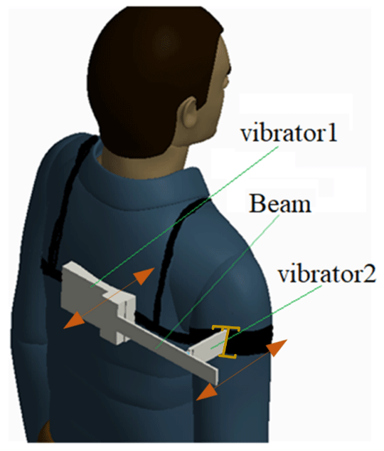
Figure 1Schematic diagram of a piezoelectric energy harvester for human body motion subjected to two excitations.
The rest of the paper is organized as follows. In Sect. 2, the dynamics equation of the harvester with two excitations is derived, and its closed-form solution is obtained in the case when the excitations can be expressed as periodic functions. In Sect. 3, the performance of the energy harvester is analyzed when the two vibrators are with the same frequency but different amplitudes and/or phases, to illustrate the abilities of the harvester, especially at low frequencies. And in Sect. 4, the conclusions are presented.
Figure 1 is a schematic diagram of the piezoelectric energy harvester for human body motion. The beam is connected at two points of the human body, which are referred as vibrator 1 and vibrator 2, respectively. As shown in Fig. 1, one end of the beam is clamped on vibrator 1, i.e., the back of the human body, and the other end of the beam is free, while vibrator 2, i.e., the arm, excites the beam at the middle part of the beam. It can be observed that the motion of vibrator 1 will be dissimilar than the motion of vibrator 2 when a human being is walking, jogging, or conducting other movements. Under this circumstance, we develop the piezoelectric energy harvester. Of course, the two vibrators may be on other parts of the human body, provided that the motions of the two vibrators are different. Otherwise, the beam will vibrate under excitation of its inertia force, similar to the normal piezoelectric energy harvester, which will also be discussed for comparison.
2.1 Derivation of the electromechanical model
The physical model and the simplified model for analysis of the harvester are presented in Figs. 2 and 3, respectively.
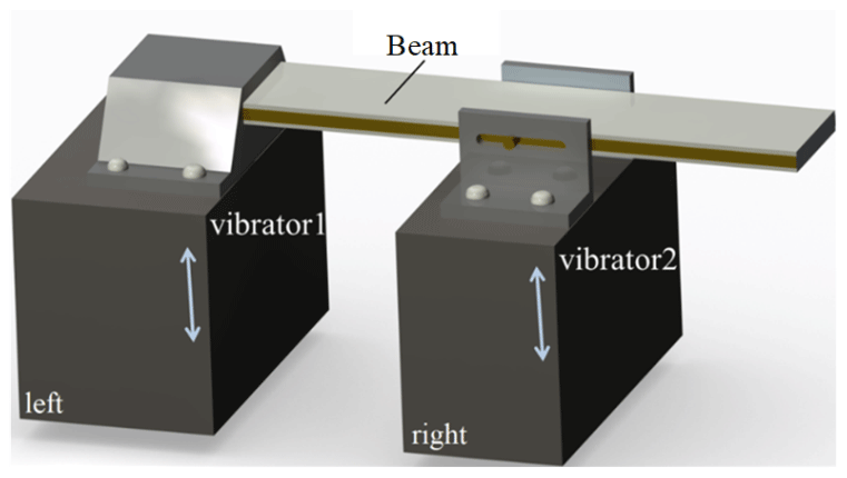
Figure 2Physical model of the piezoelectric energy harvester for human body motion subjected to two excitations.
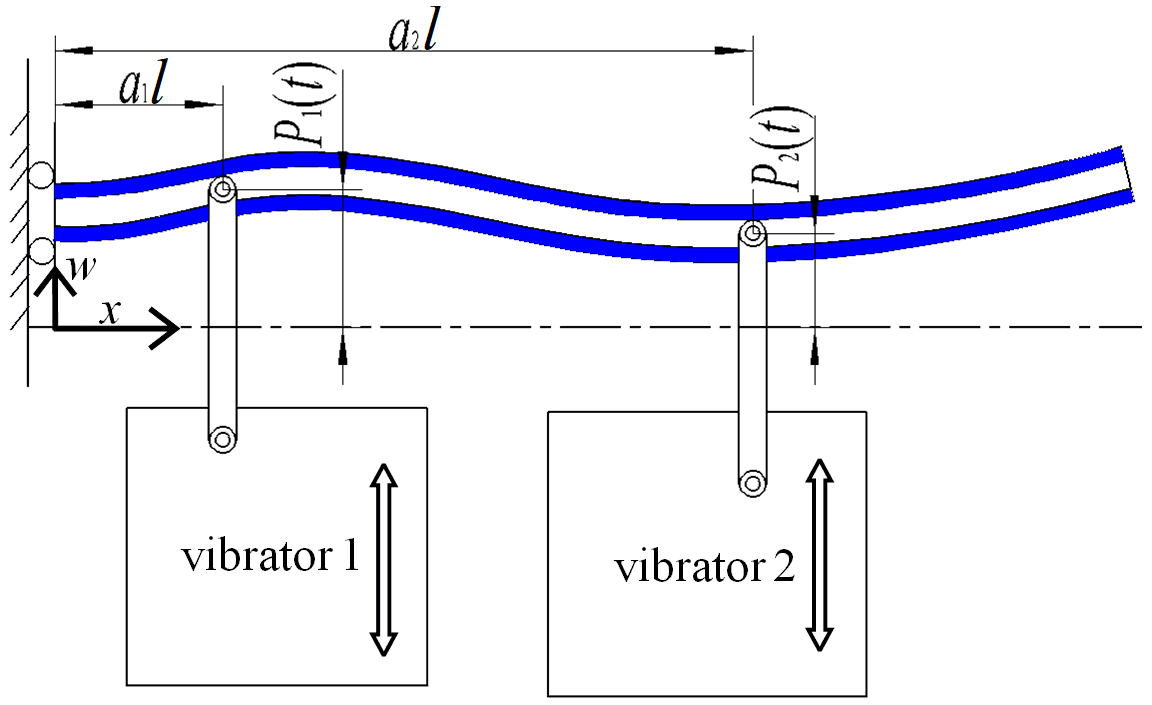
In Fig. 2, the beam is clamped onto vibrator 1. For convenience, the effects of the clamping on the beam in Fig. 2 are represented by two elements in Fig. 3; one is a sliding constraint and the other one is a transverse rheonomic constraint, P1(t) at a1l. The former implies that the bending deformation of the beam at the clamping end is neglected, the end is tolerated to move in the direction of w, and the latter allows us to consider a more general case to establish the dynamics equation. In this paper, a1 will be set to zero. Vibrator 2 is also a transverse rheonomic constraint, P2(t) acting at a2l ().
We assume the beam is an Euler–Bernoulli beam; both transverse displacements, P1(t) and P2(t), can be represented by modal coordinates. We ignore the inherent piezoelectric nonlinearities of the harvester for the reason that the acceleration is very small (Erturk and Inman, 2011; Wagner and Hagedorn, 2002).
Let the transverse displacement of the beam be w(x,t). Then, vibrators 1 and 2 can be expressed as a constraint equation as follows:
Let the rth order modal function be ϕr(x) and the modal coordinate be qr(t); the transverse displacement of the beam is
With the constraints depicted in Fig. 3, the boundary conditions of the beam is . Thus, the rth normalized model function is
where λr can be obtained by solving the following equation:
The kinetic energy of the beam can be written as
where .
The potential energy of the beam can be written as
where YI .
The complementary energy of the beam can be written as
where and α=2 when the piezoelectric layers are connected in parallel, and α=1 when the piezoelectric layers are connected in series.
The virtual work of air damping and material damping can be written as
As a conservative element, the virtual work of the load resistance is
Using κ1(t) and κ2(t) to represent Lagrange multipliers, by the Hamiltonian principle, the dynamic model can be transformed into a functional extremum problem as follows:
With the procedure of derivation presented in Appendix B, the governing equations of the energy harvester can be written as
It can be seen that Eq. (11) is an infinite-order differential algebraic equation (DAE). From Eq. (11), we obtain the undamped natural frequency of the beam ωr as follows:
and the expressions of χr and Cp as follows:
The damping ratio ζr for λr can be determined, according to the formulas of the damping ratio in Erturk and Inman (2011), by
It should be noted that the subscripts i, j, and r can be chosen independently in Eq. (15), provided that neither i nor j is equal to zero.
2.2 Closed-form solution of modeling under a periodical displacement excitation
When a human being is walking or jogging, the motions of their back and upper arm are periodic, and the experiment results of Stansfield et al. (2001) indicate that the frequencies of both parts of the human body are the same. In this paper, for simplification, we suppose that both transverse rheonomic constraints, i.e., both displacement functions of excitation Ph(t) and are periodic functions with the same frequency but different amplitude, so they can be expressed as
Then the form of the rth modal coordinates can be written as
Similarly, the ith Lagrange multiplier can be written as
and the output voltage of the energy harvester is in the form of
Substituting Eqs. (16) to (19) into Eq. (11), we get
The rth order modal equation in Eq. (20) yields
Let ; from Eq. (21), the modal coordinate can be written as
And from Eq. (17), we have
Substituting Eq. (23) into the algebraic equations in Eq. (20), we get
From Eq. (24), it can be seen that the coefficients of eIϖt in Eq. (24) should satisfy the following equations:
Substituting Eq. (23) into the electronic circuit equation in Eq. (20), we have
Let , then the formula to calculate the output voltage is
Substituting Eq. (27) into Eq. (24), we obtain
where
we have
Substituting Eq. (30) into Eq. (27), we get the formula to calculate the amplitude of the output voltage as follows:
Furthermore, the output power of the harvester can be expressed as
Next, we suppose that both transverse rheonomic constraints are quite distinct in amplitude and phase. Let be the ratio of the amplitudes and be the phase difference, respectively. Then the two transverse rheonomic constraints can be written as
The power frequency response function (FRF, Erturk and Inman, 2009) of the harvester is
In this section, we use the formulas derived in the last section to analyze the influence of the main parameters of the harvester, ε and β, as expressed in Eq. (33), on the harvesting characteristics. In the numerical calculation, we select the first eight modal functions.
To analyze the performance of the harvester at low frequencies, we expand Eq. (31) into a power series at ϖ=0; then, we have
From Eq. (35), it can be found that the output voltage v approaches zero as the frequency ϖ approaches zero. But the decreasing rate is changed with the variation of the parameters of ε and β. If the two excitations are different in the phase β≠0 or β=0 but ε≠1, then . The term O(ϖ) dominates the changing rate of the output voltage, v, of the energy harvester; the term O(ϖ2) dominates the changing rate of the output power, Po(t), in Eq. (32); and further, the term O(ϖ−2) dominates the changing rate of power FRF , P′o, in Eq. (34), where “−” means that the value of power FRF will increase as the frequency ϖ approaches zero.
If the two excitations are the same, i.e., both β=0 and ε=1, the coefficients of ϖ and ϖ2 in Eq. (35) are equal to zero, i.e., , while the coefficient of ϖ3 is not equal to zero. Then the term O(ϖ3) dominates the changing rate of the output voltage v of the energy harvester, the term O(ϖ6) dominates the changing rate of output power Po(t), and the term O(ϖ+2) dominates the changing rate of power FRF P′o, where “+” means that the value of power FRF will decrease as frequency ϖ approaches zero. Therefore, the decreasing rate of the power FRF of the harvester subjected to two different excitations is ϖ4 times faster than that of the harvester subjected to the two same excitations. In the latter case, the beam vibrates under the excitation of its inertial force, similar to the case of the normal piezoelectric energy harvester (Erturk and Inman, 2011), in which the metallic beam is fixed to the vibrator on one point, and its output voltage can be expanded into power series as
In Eqs. (35) and (36), the lowest power of ϖ is 1 and 3, respectively. As a whole, the characteristic of the harvester subjected to two different excitations is quite different from that of the normal piezoelectric energy harvester or that of the harvester subjected to the two same excitations. To present intuitive comparisons in the characteristic of the harvesters, we provide some results of a numerical analysis in which the parameters of the beam, piezoelectric material, and electronic circuit are the same as that in the classical experiment of an energy harvester with PZT-5A (Erturk and Inman, 2011).
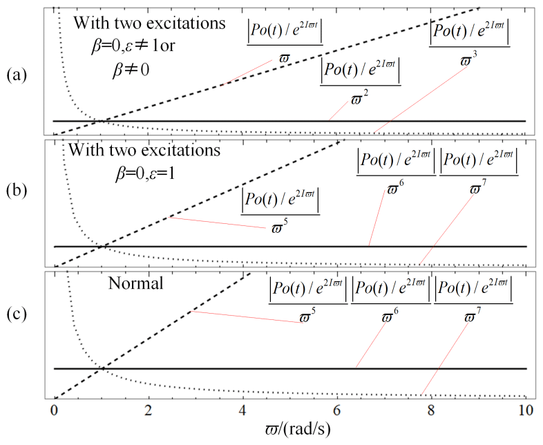
Figure 4a presents the output power generated by the harvester subjected to two different excitations. In this figure, as , the value of decreases or increases, respectively, as the frequency ϖ approaches zero. However, as n=2, the value of is a constant concerning the variations of frequency ϖ. It can be inferred that the value of is equivalent infinitesimal to ϖ2. Similarly, Fig. 4b and c show that is equivalent infinitesimal to ϖ6 for the harvester subjected to the two same excitations and the normal harvester, respectively. It is confirmed that for the three kinds of harvesters, the output powers approach zero as the frequency ϖ approaches zero, but the decreasing rate of the harvester subjected to the two different excitations is slower ϖ4 times than that of the normal harvester and the harvester subjected to the two same excitations. It means that at the low frequency, the output power of the harvester subjected to the two different excitations is certainly higher than that of the two other harvesters. In other words, as the frequency ϖ approaches zero, the harvester subjected to the two different excitations performs better than the two other harvesters.
Undoubtedly, such good performance is influenced by the parameters of the system.
Figure 5a shows the variations of power FRF P′o concerning the phase difference β and the frequency ϖ of the excitations as parameters R=105Ω, a2=0.5, and ε=1. From this figure, it can be seen that the variation trends of the power FRF for the increasing frequency are variant when β is changed. Figure 5b shows the curves of the power FRF as β=0, , and β=π, along with the curve of the normal piezoelectric energy harvester reproduced from research work by Erturk and Inman (2011).
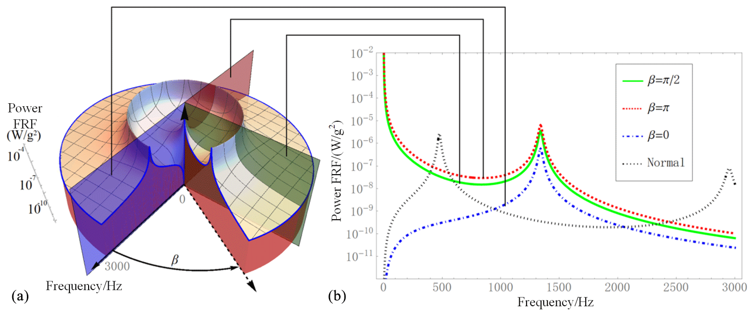
Figure 5Variation of power FRF for frequency and phase difference (R=105Ω, a2=0.5, and ε=1).
In Fig. 5b, the shapes of the curves for the harvesters subjected to the two different excitations are not the same as that for the normal piezoelectric energy harvesters and those with the two same excitations. For harvesters subjected to two different excitations such as or β=π, with the frequency increasing from 0 to 3000 Hz, the curve firstly tends downward, then upward to a local maximum around 1400 Hz, and after that downward continually. However, the curve for the normal piezoelectric energy harvester tends firstly upward, reaches the global maximum around 500Hz, then downward continually. The curve for the harvester subjected to the two same excitations tends firstly upward to one of its local maximums, then downward followed by upward to reach another local maximum, and afterwards it goes downward continually.
We are interested in the behaviors of the harvesters at low frequency. As shown in Fig. 5b, in the low-frequency interval (0–30 Hz), for the harvester subjected to two different excitations, i.e., or β=π, the values of the power FRF are monotonically decreasing with the frequency increase of excitation. In other words, the lower the frequency of excitation, the better the performance of the harvester. This indeed is an unusual characteristic of the piezoelectric energy harvester. And the minimum value is (W g−2) at 30 Hz. While in the same interval, the values of the power FRF for both the normal piezoelectric energy harvester and the harvester subjected to the two same excitations are monotonically increasing. And the former is larger than the latter; at a frequency of 30 Hz, the former is (W g−2), much lower than that of the harvester subjected to the two different excitations.
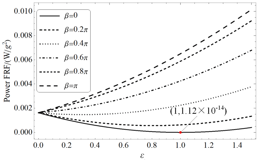
Now we turn to discuss the effects of the parameter ε on power FRF at a specific low frequency. We set the frequency to 2 Hz. Figure 6 shows the variation of the power FRF for a variation of ε for some phase difference β as R=105Ω, a2=0.5, and ϖ=2 Hz. It can be seen that for the phase differences β>0.4π, the values of the power FRF will monotonically increase with the increase of ε, while for β<0.4π, with the increase of ε, the values of the power FRF firstly decrease and then increase. The curve for β=0 is the lowest one, and the minimum value, (W g−2), occurs when ε=1, i.e., the harvester subjected to the two same excitations.
It must be noted that “power FRF” is not the actual power. The analysis of “power FRF” shows the transformation ability of the harvester and the classic harvester to the excitation motion. We will use an example to show how this difference in transformation ability is reflected in the actual power.
To compare the performance of the harvester subjected to the two different excitations with that of a normal piezoelectric energy harvester, we set f1=0.01l, ε=1, β=0.3π, and a2=0.5. The output power Po(t) of the harvester together with that of the normal piezoelectric energy harvester are depicted in Fig. 7, and four frequencies at which the comparisons are made are listed in Table 1. It should be pointed out that resistances corresponding to the maximum output power are not the same according to Eq. (32).
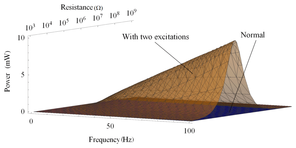
Table 1Comparisons of maximum output power at four frequencies.
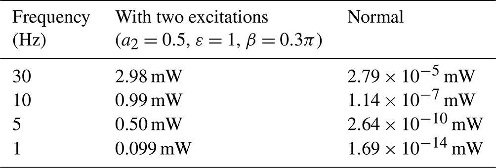
As shown in Table 1, the output power of the harvester subjected to the two excitations as ε=1 and β=0.3π is much higher than that of the normal piezoelectric energy harvester: at 30 Hz, the former is ×106 times higher than the latter; at 10 Hz, it is 8×10⁶ times; and at 1 Hz, it is 5×10¹² times. In short, at lower frequencies, the energy harvester subjected to two different excitations will generate more times power than a normal harvester.
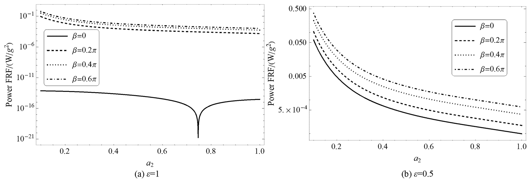
Finally, we discuss the influence of the parameter a2 on the performance of the harvester subjected to the two different excitations. We set , , R=105Ω, and ϖ=2 Hz. With Eq. (34), the power FRF P′o for the variation of parameters a2 are shown in Fig. 8. It can be seen from Fig. 8a that the trends of all the curves for β≠0 are almost the same: a smaller a2, in general, results in greater output power. But there is an exception: the curve for the case when β=0 and ε=1, i.e., the harvester subjected to the two same excitations, not only for its trend but for the value of the output power which is lower. However, in Fig. 8b, for β=0, these distinctions do not exist. It also indicates that differences between the two excitations are crucial for obtaining a better performance of the energy harvester with two excitations.
For harvesting energy from human body motion, it is proposed in this paper to connect two parts of the human body with different transversal reciprocating excitations using a metallic beam attached with piezoelectric ceramics layers to form the energy harvester. In this paper, we emphasize the analysis of the characteristics of the energy harvester subjected to two different excitations.
Employing the Hamiltonian principle, the governing equation of the piezoelectric energy harvester is established. Assuming that both the two excitations are periodic functions, the closed-form solutions of the dynamics equation are obtained. Utilizing the closed-form solutions, the influences of the differences in the amplitude and phase difference of the excitations on the performance of the harvester are analyzed together with numerical examples.
The results show that as long as there exists some differences between the two excitations, either in amplitude and/or in phase difference, the energy harvester can generate more output power at low frequencies, and the larger the differences are, the more the output power will be generated. Contrasting the normal piezoelectric energy harvester and the harvester subjected to two of the same excitations, the harvester subjected to two different excitations exhibits a characteristic: the output power increases with the decrease of frequency. This unusual feature enables the proposed harvester to be quite suitable to harvest energy from human body motions.
In this paper, the analysis is based on a mathematical model. In future research, a prototype device will be built to validate the results experimentally. Additionally, the same kind of harvester subjected to more than two excitations with different excitations will be studied.
| l | length of beam |
| a1, a2 | position parameters of vibrator 1 and |
| vibrator 2 | |
| t | time |
| Ph(t) | the hth displacement functions |
| the hth constraint equation | |
| w(x,t) | transverse displacement of the beam |
| ϕr(x) | the rth order modal function of the beam |
| qr(t) | the rth modal coordinate |
| I | |
| ρs | density of the metal layer |
| ρp | density of the piezoelectric layer |
| hs | thickness of the metal layer |
| hp | thickness of the piezoelectric layers |
| b | width of the beam |
| c11 | elastic constant of the piezoelectric layers |
| E | elastic modulus of the metal layer |
| m | the mass per unit length of the beam |
| YI | bending stiffness |
| Ip, Is, Ib | cross-sectional area moment of inertia of |
| the metal layer, inertia of piezoelectric | |
| layers, the whole beam | |
| ε33 | dielectric constant |
| e31 | piezoelectric constant |
| Qs | virtual work of air damping and |
| material damping | |
| cs | average material damping coefficient |
| ca | air damping coefficient |
| QR | virtual work of the load resistance |
| v(t) | voltage |
| κ(t) | Lagrange multiplier |
| ζr | rth order damping ratio |
| ωr | natural frequency of the beam |
| Po(t) | output power |
| P′o | power FRF |
| fr | amplitude of the rth vibrators |
| ϖ | frequency of the vibrators |
| χr | electromechanical coupling coefficient |
| Cp | capacitance |
| Hr | amplitude of rth modal coordinates |
| κi | amplitude of ith Lagrange multipliers |
| Γr | grouped term 1 |
| ξij | grouped term 2 |
| β | phase difference |
Let
where δi is the Dirac Dirichlet function. Using Eq. (B1) in Eq. (10), it becomes
Integrate Eq. (B2) by parts, and it becomes
In Eq. (B3), the coefficients of δw, δv, δκ1, and δκ2 equal 0. Notice that , where H is the Heaviside function. Using Eq. (B1) in Eq. (B3), we get
Use Eq. (2) in Eqs. (B4)–(B6) and multiply ϕr(x) at both sides of the equations. Integrate equations from 0 to l, and using , one can obtain Eq. (11).
All data included in this study are available upon request from the corresponding author.
WD conceived the idea, developed the method, performed analysis, and wrote the majority of the paper. JX organized the contents and edited the language.
The contact author has declared that neither of the authors has any competing interests.
Publisher's note: Copernicus Publications remains neutral with regard to jurisdictional claims in published maps and institutional affiliations.
The authors would like to acknowledge the financial support of the NSFC (National Natural Science Foundation of China; grant nos. 51575457 and 52175031).
This research has been supported by the National Natural Science Foundation of China (NSFC; grant nos. 52175031 and 51575457).
This paper was edited by Dario Richiedei and reviewed by two anonymous referees.
Blad, B. and Tolou, N.: On the Efficiency of Energy Harvesters: A Classification of Dynamics in Miniaturized Generators Under Low-Frequency Excitation, J. Intel. Mat. Syst. Str., 30, 2436–2446, https://doi.org/10.1177/1045389X19862621, 2019.
Dechant, E., Fedulov, F., Chashin, D. V., Fetisov, L. Y., Fetisov, Y. K., and Shamonin, M.: Low-Frequency, Broadband Vibration Energy Harvester Using Coupled Oscillators and Frequency Up-Conversion by Mechanical Stoppers, Smart Mater. Struct., 26, 065021, https://doi.org/10.1088/1361-665X/aa6e92, 2017.
Erturk, A. and Inman, D. J.: An experimentally validated bimorph cantilever model for piezoelectric energy harvesting from base excitations, Smart Mater. Struct., 18, 025009, https://doi.org/10.1088/0964-1726/18/2/025009, 2009.
Erturk, A. and Inman, D. J.: Piezoelectric energy harvesting, John Wiley & Sons, Sussex, https://doi.org/10.1002/9781119991151, 2011.
George, A., Moline, D., and Wagner, J.: Arm Motion Dynamics to Excite a Mobile Energy Harvesting Autowinder, in: Proceedings of the ASME 2020 Dynamic Systems and Control Conference, Virtual, Online, 5–7 October 2020, DSCC2020-3109: V002T32A001, https://doi.org/10.1115/DSCC2020-3109, 2020.
Green, P. L. Papatheou, E., and Sims, N. D.: Energy Harvesting from Human Motion and Bridge Vibrations: An Evaluation of Current Nonlinear Energy Harvesting Solutions, J. Intel. Mat. Syst. Str., 24, 1494–1505, https://doi.org/10.1177/1045389X12473379, 2013.
Halim, M. A. and Park, J. Y.: Theoretical Modeling and Analysis of Mechanical Impact Driven and Frequency Up-Converted Piezoelectric Energy Harvester for Low-Frequency and Wide-Bandwidth Operation, Sensor. Actuat. A-Phys., 208, 56–65, https://doi.org/10.1016/j.sna.2013.12.033, 2014.
Hallal, P. C. and Pratt, M.: Physical activity: moving from words to action, Lancet Glob. Health., 8, e867–e868, https://doi.org/10.1016/S2214-109X(20)30256-4, 2020.
Leadenham, S. and Erturk, A.: Nonlinear M-shaped broadband piezoelectric energy harvester for very low base accelerations: primary and secondary resonances, Smart Mater. Struct., 24, 055021, https://doi.org/10.1088/0964-1726/24/5/055021, 2015.
Liu, H., Lee, C., Kobayashi, T., Tay, C. J., and Quan, C.: A New S-Shaped MEMS PZT Cantilever for Energy Harvesting from Low Frequency Vibrations Below 30 Hz, Microsyst. Technol., 18, 497–506, https://doi.org/10.1007/s00542-012-1424-1, 2012.
Maamer, B., Boughamoura, A., Fath El-Bab, A. M. R., Francis, L. A., and Tounsi, F.: A Review on Design Improvements and Techniques for Mechanical Energy Harvesting Using Piezoelectric and Electromagnetic Schemes, Energ. Convers. Manage., 199, 111973, https://doi.org/10.1016/j.enconman.2019.111973, 2019.
Ren, D., Aubert-Kato, N., Anzai, E., Ohta, Y., and Tripette, J.: Random Forest Algorithms for Recognizing Daily Life Activities Using Plantar Pressure Information: A Smart-Shoe Study, PeerJ, 8, e10170, https://doi.org/10.7717/peerj.10170, 2020.
Roundy, S. and Wright, P. K.: A Piezoelectric Vibration Based Generator for Wireless Electronics, Smart Mater. Struct., 13, 1131–1142, https://doi.org/10.1088/0964-1726/13/5/018, 2004.
Sodano, H. A., Inman, D. J., and Park, G.: A Review of Power Harvesting from Vibration Using Piezoelectric Materials, The Shock and Vibration Digest, 36, 197–206, 2004.
Stansfield, B. W., Hillman, S. J., Hazlewood, M. E., Lawson, A. A., Mann, A. M., Loudon, I. R., and Robb, J. E.: Normalised speed, not age, characterizes ground reaction force patterns in 5–12 year old children walking at self-selected speeds, J. Paediatr. Orthoped., 21, 395–402, https://doi.org/10.1097/01241398-200105000-00026, 2001.
Wagner, U. V. and Hagedorn, P.: Piezo–beam systems subjected to weak electric field: experiments and modelling of non-linearities, J. Sound Vib., 256, 861–872, https://doi.org/10.1006/jsvi.2002.5024, 2002.
- Abstract
- Introduction
- Modeling of the harvester for human body motion subjected to two excitations
- The performance of the harvester and discussions
- Conclusion
- Appendix A: Nomenclature
- Appendix B: Derivation of Eq. (11)
- Data availability
- Author contributions
- Competing interests
- Disclaimer
- Acknowledgements
- Financial support
- Review statement
- References