the Creative Commons Attribution 4.0 License.
the Creative Commons Attribution 4.0 License.
 | 20 Nov 2023
Gear injury equilibrium-oriented self-adjusted shifting strategy and advanced servo control
Zhichao Lyu
Guangqiang Wu
Qiming Wang
Heqi Yan
The application of a self-adjusted strategy has received increasing attention in current transmission design. This paper proposes a gear injury equilibrium oriented self-adjusted shifting strategy (EASS), which can make injury of different gears consistent. First, the injury value of different gears was judged in real time, and the working time of the gear with the largest injury value was reduced by adjusting the shift curve. Second, by considering key points as constraints, an optimal displacement trajectory for a synchronizer was proposed, and then a compound control method using adaptive nonsingular global fast-terminal sliding-mode control (AN-GFTSMC) was developed, which enables a high tracking performance and a better parameter perturbation rejection ability. Finally, both the simulation and real-vehicle experimental results showed that, compared with conventional control, the designed control strategy had good performance: response time was decreased, gear injury tended to be consistent, and transmission reliability was improved.
- Article
(7348 KB) - Full-text XML
- BibTeX
- EndNote


Fuel economy and emissions are the first two most important targets of power-train design, and reliability optimization has been the third core part (Wu, 2010) as gearbox reliability directly affects the vehicle-driving experience as well as the overall reliability and safety. Currently, more research studies about fuel economy and emission optimization that aim at reliability are being proposed. There is still space for traditional methods towards lightweight design and improving the fuel economy. So, this paper tries to propose a new form of health monitoring system named the equilibrium oriented self-adjusted shifting strategy (EASS) alongside a high-performance tracking control algorithm for reliability optimization.
Related studies have presented lots of methods for gear injury monitoring (Wu et al., 2023; Xia et al., 2020; Wang et al., 2015). Basoalto and Papaelias (2020) presented a finite-element gear pair model, based on a physics-based dislocation slip model, to quantify and predict gearbox injury. Jiang et al. (2018) performed a lifecycle assessment that aimed to evaluate the environmental impact of a wind turbine gearbox based on its calculated reliability, while another reliability prediction method was applied stepwise to estimate the total failure rate of an offshore wind turbine gearbox (Bhardwaj et al., 2019). In Dhiman's research (Dhiman et al., 2023), a feature selection-based methodology that essentially works on regression models was used to identify faulty scenarios. Reducing gear working time according to the EASS is a feasible way of optimizing gear reliability, and it can be realized by adjustment of the shift curve (Wu and Si, 2013) through synchronizer control. Barathiraja et al. (2021) used a regression analysis to study the critical factors and levels for synchronizer wear reduction and thereby proposed various means of improving the life of the synchronizer. A detailed multibody dynamic model (Walker and Zhang, 2014; Walker et al., 2017) is proposed and widely used. In the Shen et al. (2014) paper, a model of a shifting actuator is established and a nonlinear system sliding-mode controller of the gearshift motor is constructed based on the control principle of a variable structure sliding mode (Yang et al., 2008). An advanced synchronizer control algorithm with good tracking performance and robustness can improve the overall performance of the whole system, and the nonsingular terminal sliding-mode control (NTSMC) with optimization towards “adaptive” is the current preferred option (Mustafa et al., 2020; Anh et al., 2019; Duc et al., 2018; Hashtarkhani and Khosrowjerdi, 2019). An adaptive sliding-mode control was presented for use in cases where explicit knowledge of the system dynamics is not available (Li and Yurkovich, 2000). A fault-tolerant attitude controller based on adaptive control and fast-terminal sliding-control theory was designed to handle actuator uncertainties (Qi et al., 2019). Adaptive sliding-mode control is also widely adopted for trajectory tracking and disturbance observation (Li et al., 2019; Yi and Zhai, 2019; Yan et al., 2021; Sun et al., 2021; Rabiee et al., 2019). An adaptive nonsingular fast-terminal sliding mode (ANTSMC) has a great ability to handle system uncertainty and external disturbance (Boukattaya et al., 2018; Labbadi and Cherkaoui, 2020; Rodriguez et al., 2022). In Wang and Hao (2021), a robust nonsingular fast-terminal sliding-mode control scheme with adaptive neural networks was presented for a class of nonlinear systems with unknown bounds of uncertainties. In addition, a novel fast nonsingular terminal sliding-mode surface was designed using an adaptive methodology, with adaptive update laws employed to estimate the boundaries of various uncertainties (Miao et al., 2019). Wang and Hao (2021) utilized an adaptive sliding-mode control issue for switched nonlinear systems with both matched and mismatched uncertainties. An adaptive sliding-mode control law was also designed by means of a back-stepping method to compensate for the unknown and uncertain parts of aircraft systems (Zhuang et al., 2021). Adaptive sliding-mode control has thus been widely studied in recent years, particularly because of its obvious advantages in nonlinear systems with uncertainties (Ghorbani et al., 2021; Liu et al., 2019; Nguyen et al., 2019).
Considering that previous reliability-relevant research studies rarely mention self-adjusted strategy, this paper proposed an EASS alongside an adaptive nonsingular global fast-terminal sliding-mode control (AN-GFTSMC) for reliability optimization as gear injury is one of the main issues with transmission reliability. Due to the different environments and driving styles with which different drivers use vehicles, the working strengths and working times of different gears are different. Therefore, the overall strength of the transmission gears needs to be increased during the design process. However, this process can lead to excessive redundancy in the strength of the transmission gears, which not only reduces the economy of the vehicle, contrary to lightweight design but also increases manufacturing costs. The method designed in this article starts by predicting the injury values of transmission gears, comparing the injury values of different gears in real time, and adjusting the gears in time, making the injury values of each gear in the transmission tend to be consistent and solving the above problems.
This paper is organized as follows. First, the real-time value of the gear injury is calculated by cooperating with the Technische Universität Darmstadt in Germany (Esser et al., 2020); this is used as the input of the EASS. The second section designs the EASS specifically, which can intelligently adjust the shift curve of the transmission by comparing the injury value of each gear in real time in order to make each gear's injury tend to be consistent. As a means of realizing the EASS, Sect. 3 proposes a novel AN-GFTSMC for a synchronizer based on building an actuation hydraulic and mechanical model. Furthermore, an optimal trajectory for the synchronizer is deployed considering the nonlinear force of its operating process, enabling a high tracking performance. Finally, both the simulation and real-vehicle experimental results show that each gear's injury tends to be consistent by adopting the EASS, and the AN-GFTSMC possesses a good ability to improve the response performance of the synchronizer system, which improves transmission reliability and prolongs its lifespan. This could also be good guidance for industrial design of transmissions, which has positive significance for durability and light weight.
2.1 Gear injury equilibrium oriented self-adjusted strategy
Based on real-time monitoring of the injury to each gear, the identity of the gear with the largest injury at a certain moment can be obtained. Its adjacent gear with the minimum injury can then be assessed and a corresponding gear adjustment carried out so that the gear with the larger injury value is given a shorter working time and the gear with the smaller injury value has a longer working time.
Specific workflows and principles reflecting this are shown in Fig. 1, where GiD represents the injury value of the ith gear (gear i).
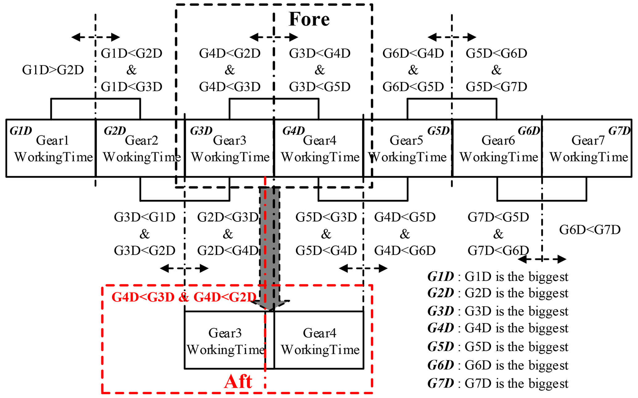
Taking a seven-gear transmission as an example and real-time monitoring, the injury values of the seven gears are as follows.
-
The gear with the maximum injury value was identified, in this case as gear 3.
-
The injury values of the two gears adjacent to gear 3, i.e., gear 2 and gear 4, were assessed, and the gear with the smaller injury value was identified.
-
If the injury to gear 4 is less, then the EASS is applied to this gear, increasing the working time of gear 4 by upshifting from gear 3 to gear 4 in advance and delaying downshifting from gear 4 to gear 3. If the injury of gear 2 is less, upshifting to gear 3 will be delayed and downshifting from gear 3 to gear 2 advanced.
-
After the relevant gear adjustment, the injury value of gear 3 should eventually regress from the maximum. This is assessed by judging the injury to all seven gears in real time. After the vehicle runs for a period and if the injury value of gear 4 (or gear 2, as relevant) becomes the maximum, steps (2) to (3) are repeated for the gears adjacent to the new maximum.
-
The injury values of the two gears adjacent to gear 4, i.e., gear 3 and gear 5, were assessed and the gear with the smaller injury value was identified.
-
If the injury to gear 3 is less, then the EASS is applied to this gear, increasing the working time of gear 3 by downshifting from gear 4 to gear 3 in advance and then upshifting from gear 3 to gear 4. If the injury to gear 5 is less, upshifting to gear 5 will be in advance and downshifting from gear 5 to gear 4 thus delayed.
Continuous loops of this strategy will eventually lead to the injury values of all gears reaching equilibrium, making the transmission life longer overall.
2.2 Gear-shifting strategy
Continue to discuss example (3) in Sect. 2.1. As shown in Fig. 2, the upshift from gear 3 to gear 4 is prioritized on the premise that the pre-select curve remains unchanged, the working time of gear 3 is reduced, and the working time of gear 4 is increased by moving the upshift curve left. Continue to discuss example (6) in Sect. 2.1. On the condition of downshift from gear 4 to gear 3, as shown in Fig. 3, and on the premise that the pre-select curve remains unchanged, moving the downshift curve left reduces the working time of gear 3 and increases the working time of gear 4. Other situations are similar.

uUSA is the actual adjusted upshift curve, uUS is the original upshift curve, uUPSB is the boundary of the upshift curve, λiGearDamg is the injury normalization value of the ith gear calculated from the injury, uUPSB is the pre-select upshift curve, and ΔUp is the speed change value corresponding to the difference between the boundary of the upshift curve and the pre-select curve that is constrained by the current vehicle speed and the response time of the synchronizer control system. In order to ensure a smooth shift, the pre-select action must be completed before responding to the shift request command, so the following inequality must be satisfied.
is the current driving acceleration of the vehicle, and tS is the response time of the synchronizer control system.
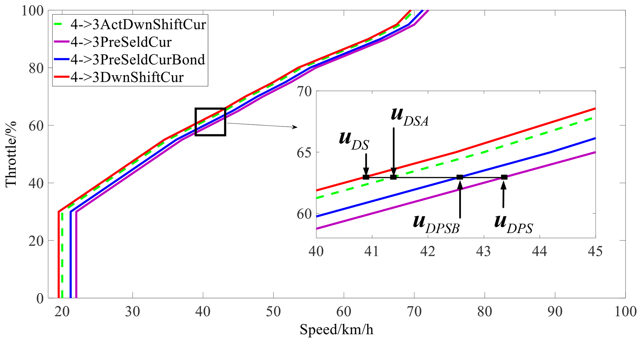
uDSA is the actual adjusted downshift curve, uDS is the original downshift curve, uDPSB is the boundary of the downshift curve, λiGearDamg is the injury normalization value of the ith gear, and uDPS is the pre-select downshift curve. ΔDwn is the speed change value corresponding to the difference between the boundary of the downshift curve and the pre-select curve, which is constrained by the current vehicle speed and the response time of the synchronizer control system. In order to ensure a smooth shift, the pre-select action must be completed before responding to the shift request, so the following inequality must be met.
is the current driving deceleration of the vehicle, and tS is the response time of the synchronizer control system.
According to Eqs. (3) and (6), by minimizing the response time tS of the synchronizer control system, ΔUp and ΔDwn can be minimized, and this should also maximize the effect of the EASS.
In order to optimize the control effect of the EASS, a synchronizer control algorithm is proposed to minimize the response time tS.
3.1 Modeling of the hydraulic actuation system
The hydraulic actuation system (HAS) consists of two independent valve systems. Each of these systems consists of one variable-bleed solenoid (VBS) and one two-position four-way valve.
As shown in Fig. 4, the VBS is marked in yellow and is the core of the HAS.
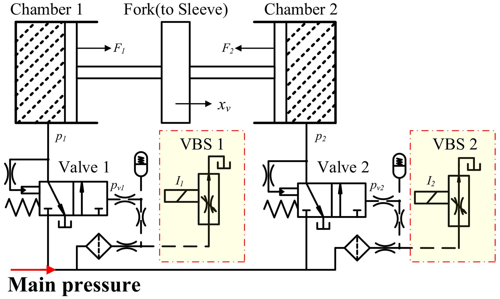
VBS suppliers such as BorgWarner guarantee that the output pressure, pvi of a VBS, is stably linearized with the input current Ii, and pvi controls the opening area of valve i, which determines the pressure pi of chamber i. The equation of motion can then be expressed according to Newton's second law as follows.
xv is the displacement of the fork. m is the mass of the motion part of the synchronizer, which varies with the different operating stages but is specifically bounded. ς is the hydraulic viscosity coefficient. Fsync is the resistance of the synchronizer in the operating process, and F1 and F2 are the hydraulic actuations of the two independent valve systems, respectively.
When the hydraulic system is actuated, its cavity must be filled to allow the output of pressure. Based on the viscosity characteristics of hydraulic oil, when establishing the oil pressure equation for the HAS, the system has certain time-delay characteristics like those shown in Eq. (8).
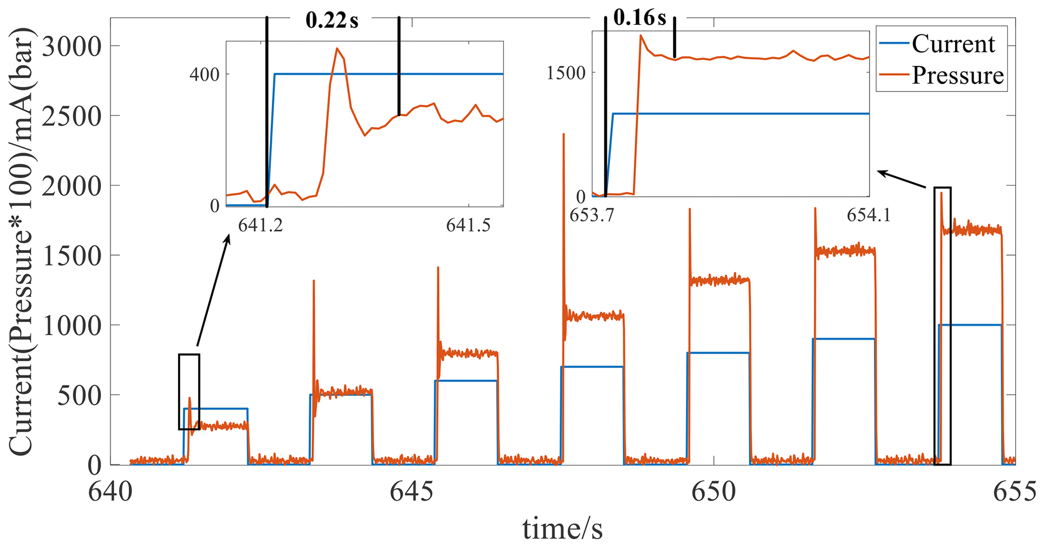
Ivi is the input current of VBSim, and si is the hydraulic actuation area of the valve. i is the number of valves. The term pi(⋅) in Eqs. (8) and (9) denotes the gain function of valve i, while the coefficients of the gain function can be identified by large amounts of experimental data as shown in Fig. 5.
, , , and .
ηv in Eq. (8) is the nominal value of the time-delay characteristic parameter, which cannot however be accurately solved for. Only the range of ηv can be acquired based on large quantities of experimental data as shown in Fig. 5, and this can be expressed as follows.
and are the upper and lower bounds of ηv, respectively.
3.2 Modeling of the synchronizer mechanical system
The synchronizer's operating process can be divided into six stages: sleeve indexation, synchronization, ring deviation, free flying, gear deviation, and lock-up.
(1) Sleeve indexation
The external force at this stage comes mainly from the deformation of the strut spring of the self-locking device and the deformation of the detent spring of the gear-locking device, which both have positive correlations with displacement, as shown in Fig. 6.
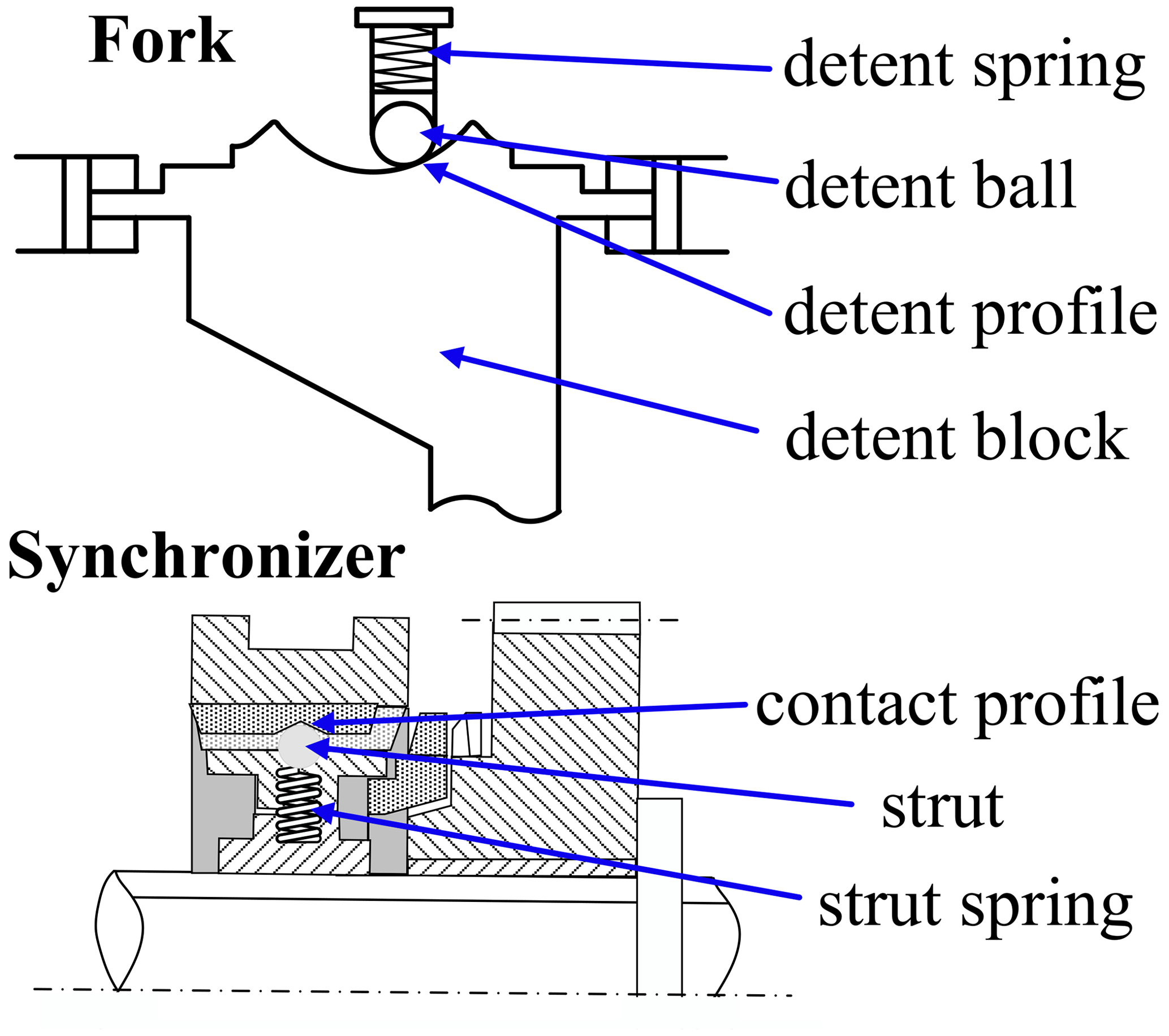
An analysis of the force on the synchronizer at this stage shows that it is subject to self-locking resistance Fslc and gear-locking resistance FB.
kslc is the elastic coefficient of the strut spring, nsd is the number of synchronizer sliders, χslc is the slope angle of the contact profile between the sleeve and the strut, μslc is the friction coefficient of the contact profile between the sleeve and the strut, kB is the elastic coefficient of the detent spring of the gear-locking device, χB is the slope angle of the detent profile, and μB is the friction coefficient of the contact surface between the detent ball and the detent block.
(2) Synchronization
Analysis of the synchronization stage shows that, during this period, the fork does not move, and the force on the fork is used for the synchronization of the ring and the gear ring as shown in Fig. 7.
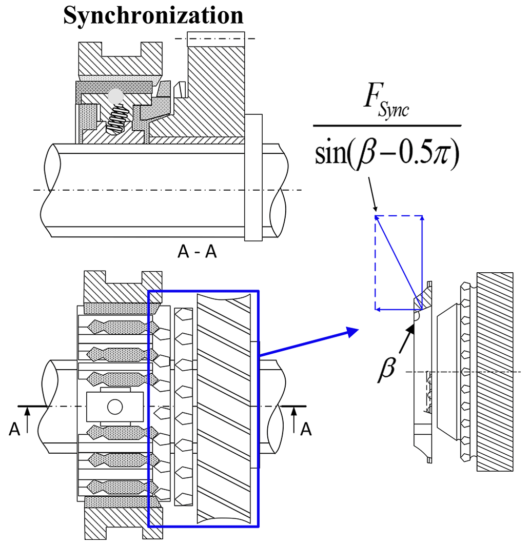
This means the following.
μring is the friction coefficient between the ring cone and the gear ring cone, θGear is the rotation angle of the gear, β is the cone angle of the ring, and FSync is the axial force at the synchronization stage.
(3) Ring deviation
As shown in Fig. 8, the external force at this stage mainly arises from the torque exerted on the ring.
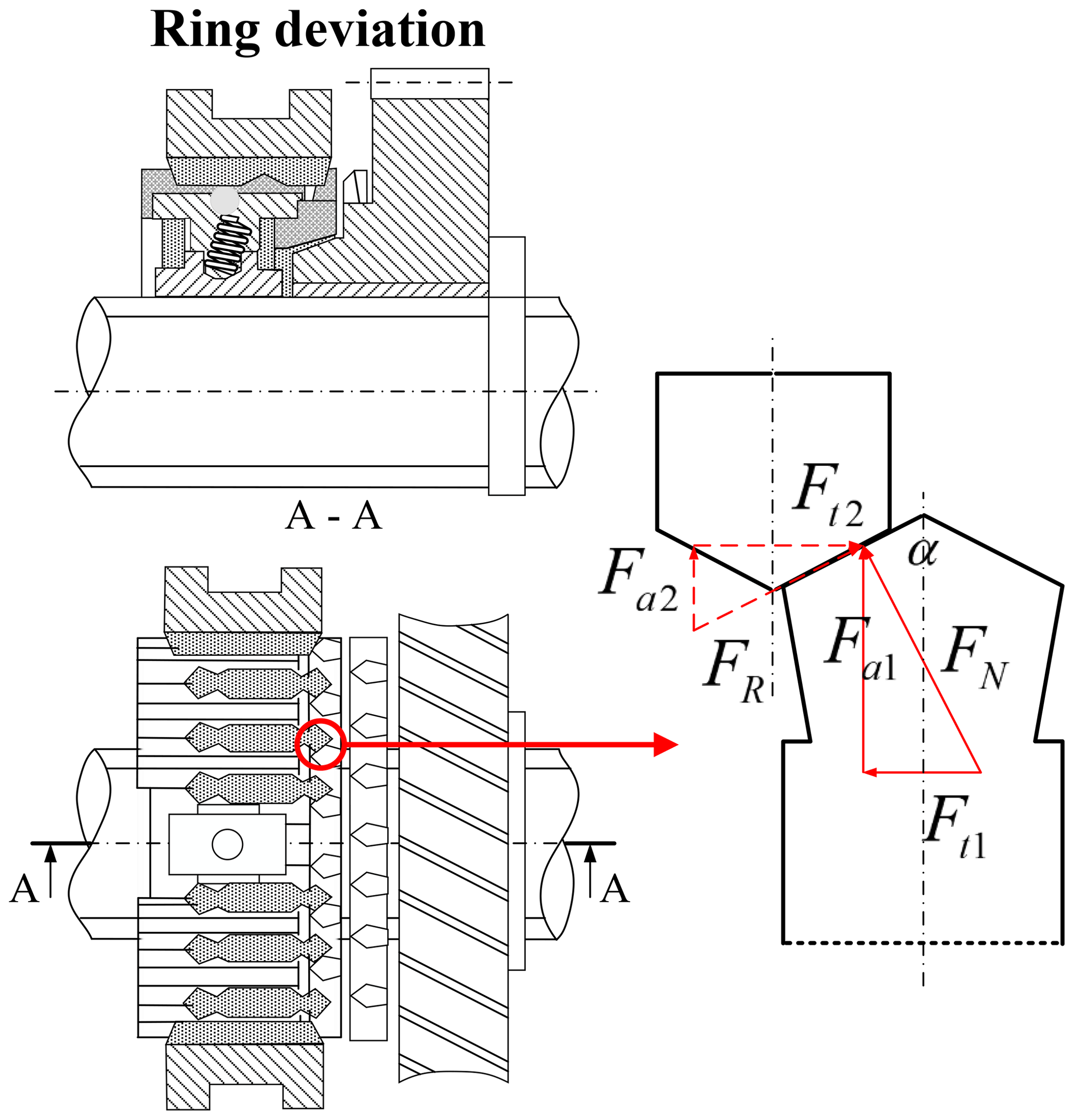
The force analysis is therefore as follows.
FRD is the axial force at the ring deviation stage, α is the chamfer angle of the sleeve dog, rsync is the radius of the ring, JGear is the rotational inertia coefficient of those parts connected to the gear, JRing is the rotational inertia coefficient of the ring, μFric is the equivalent friction coefficient of the parts connected with the gear, and μRD is the friction coefficient of the dog.
(4) Free flying
Analysis of the free-flying stage shows that the external force is mainly derived from the motion of the moving components.
(5) Gear deviation
As shown in Fig. 9, the external force at this stage mainly arises from the torque applied to the gear ring and the friction between the ring and the gear ring.
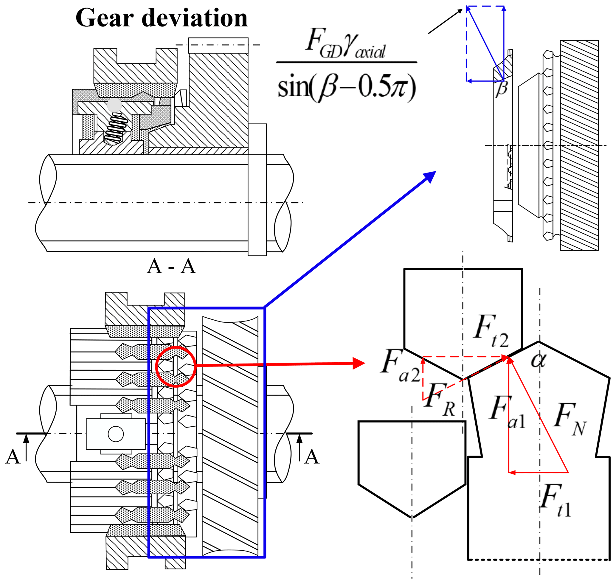
The force analysis is as follows.
, , and . FGD is the axial force at the gear deviation stage, and μGD is the friction coefficient of the dog. γaxial is the axial force coefficient, which is generally very small.
(6) Lock-up
Analysis of the lock-up stage shows that the external force is mainly derived from the motion of the moving components.
Thus, the overall process resistance suffered by the synchronizer during operation can be described in the following forms.
The critical points at 1.1, 2.5, 6, 7, and 9 mm are obtained by measuring the real synchronizer.

4.1 Controller design based on AN-GFTSMC
The error between actual and target displacement is defined as follows.
xd is the target displacement.
Some model parameters (as in Eq. 17), e.g., the synchronizer motion part mass, m, and the hydraulic system time-delay characteristic parameter, ηv, cannot be obtained accurately. Thus, in order to guarantee rapid and high-precision tracking performance under the parameter perturbations with constraint input, a novel AN-GFTSMC for an uncertain system is proposed. Its sliding-mode surface is defined as follows.
σ0, σ1, and σ2, respectively, are positive parameters. , , and . o1 and o2 are chosen such that , where qi and pi are positive odd numbers and pi>qi. Based on this, the variables e, , and will converge to zero in a finite period of time.
The control input is defined as follows.
Equation (23) has the following.
k31 and k32 are positive integers, o3 is such that , and q3 and p3 are positive odd numbers.
4.2 Stability proof
Take valve 1 as an example and define a Lyapunov candidate as follows.
This leads to the following.
Bring Eqs. (24) and (31) into Eq. (33).
The simplified Eq. (34) is as follows.
The simplified Eq. (35) is as follows.
This formula has the following.
Equations (29) and (30) show that
and
Equations (27) and (38) show that
and
Since k31 and k32 are selected as positive integers,
According to Eq. (26),
Overall,
When s=0, , the system is asymptotically stable on a large scale.
5.1 Parameter settings
All the parameters used in this paper are shown in Table 1.
According to the analysis of Sect. 3.2, the fork moves to the set points at 1.5, 6, and 9 mm with zero velocity. As shown in Fig. 10, to reduce the synchronizer's impact, the fork's motion trajectory must meet the following conditions.
-
Condition1:
-
Condition2:
-
Condition3:
-
Condition4:
The designed displacement trajectory in this paper is shown in Eqs. (46) and (47), as illustrated in Fig. 10. The velocity trajectory must satisfy the Lipschitz condition as Condition 1, where ν is a positive integer. Ti is also shown in Fig. 10.
The target displacement trajectory can be obtained as follows.
Parameter perturbations are defined as follows.
and Δm are the upper and lower bounds of m.
In Eqs. (46) to (49), t is time, and Ti is as shown in Fig. 10. By setting Ti, the synchronizer performance can be adjusted. This section's design is T3=90 ms.
5.2 AN-GFTSMC analysis
The control algorithm was verified by using the Application SoftWare (ASW) for the dual-clutch transmission (DCT) developed by the researchers' laboratory. Figure 11 shows the result of synchronizer displacement as compared with the conventional control. Using the AN-GFTSMC in the sleeve indexation stage reduced the action time from 70 to 15 ms, a 78.6 % improvement. At the ring deviation + free-flying stage, the action time was reduced from 150 to 45 ms, a 70 % improvement. At the gear deviation + lock-up stage, the action time was reduced from 70 to 30 ms, giving a 57.1 % improvement. The overall actuation time was thus improved by 43.3 %.
Figure 12 demonstrates the velocity results for the synchronizer. Under conventional control, its peak velocities marked in the blue box were 2.2 m s−1 in the sleeve indexation to synchronization stage, 4.4 m s−1 in the ring deviation + free-flying stage, and 5.5 m s−1 in the gear deviation + lock-up stage. Its instantaneous velocities marked in the blue circle in the free-flying to gear deviation stage were 5.5 and 2.2 m s−1 at the end of the process. There should be an instantaneous zeroing of velocity in the sleeve indexation to synchronization stage, the free-flying to gear deviation stage, and at the end of the process, which is the root cause of the impact. However, the results show in the red box that the maximum velocities under AN-GFTSMC were 11.5 m s−1 in the sleeve indexation to synchronization stage, 17.1 m s−1 in the ring deviation + free-flying stage, and 15.7 m s−1 in the gear deviation + lock-up stage. As marked in the red circle in the free-flying to gear deviation stage at 230 ms and the end of the process at 260 ms, the velocity reached 0 m s−1, satisfying Eq. (47) and achieving the target trajectory shown in Fig. 10. As compared with conventional control, the peak velocity under AN-GFTSMC was thus optimized by 5.2 times in the sleeve indexation to synchronization stage, by 3.8 times during the ring deviation + free-flying stage, and by 2.9 times during the gear deviation + lock-up stage. There was no impact during the whole process.
5.3 EASS experiment
5.3.1 Simulation test
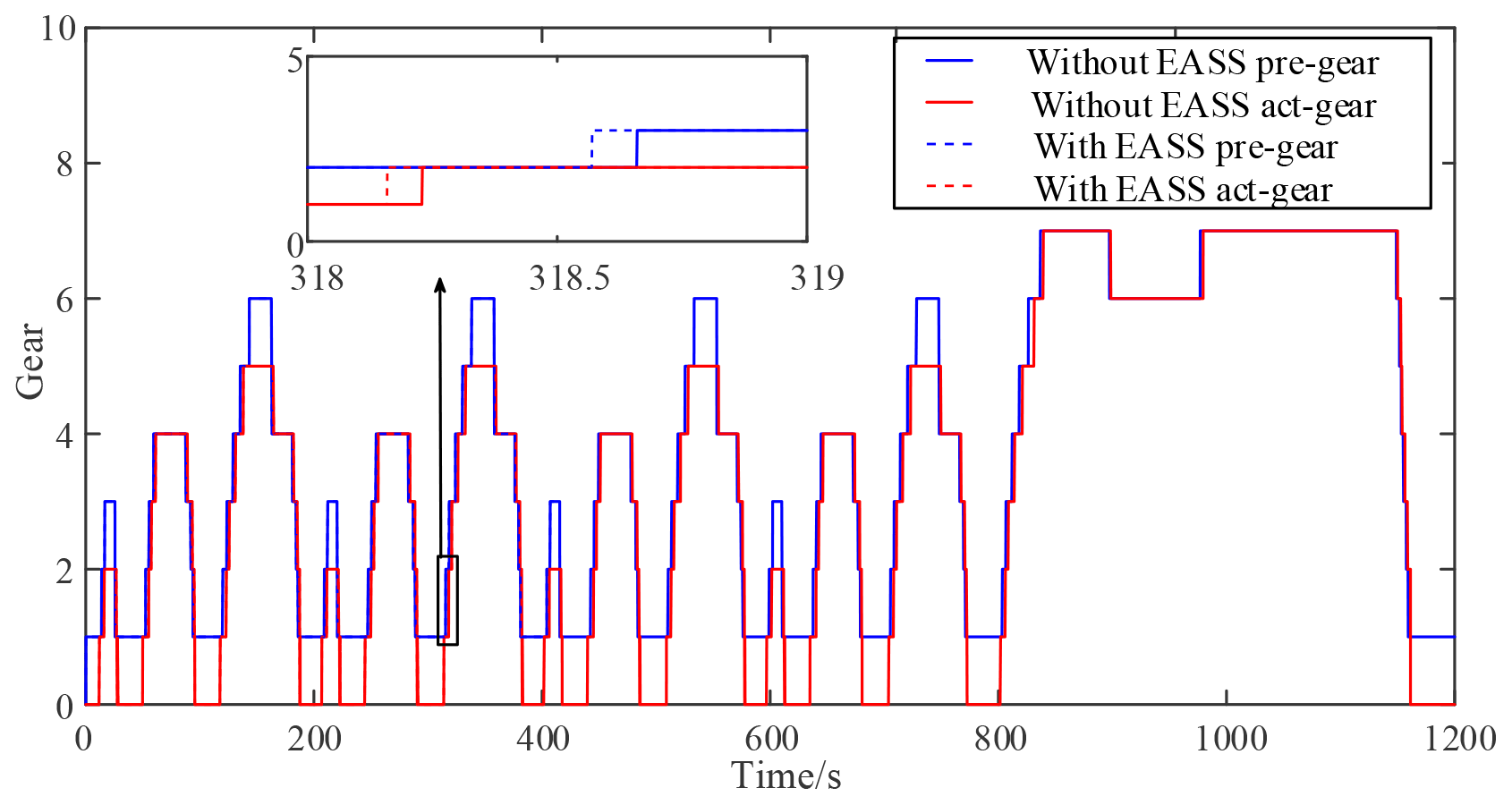
The initial condition was that gear 1 took maximum injury. The EASS was then verified in the New European Driving Cycle (NEDC) condition. Figures 13 and 14 show the speed and gear results, respectively, of the NEDC cycle. Figure 13 showed that the blue line, red line, and red-dot line represent the target speed, the speed without the EASS, and the speed with the EASS, respectively. As shown in Fig. 14, the proposed strategy also reduced the usage time of gear 1 by means of upshifting to gear 2 in advance, thus reducing the injury to gear 1. In this figure, the blue line and blue-dot line show the pre-select gear and the actual gear without the EASS, respectively, while the red line and red-dot line are the pre-select gear and the actual gear with the EASS, respectively.
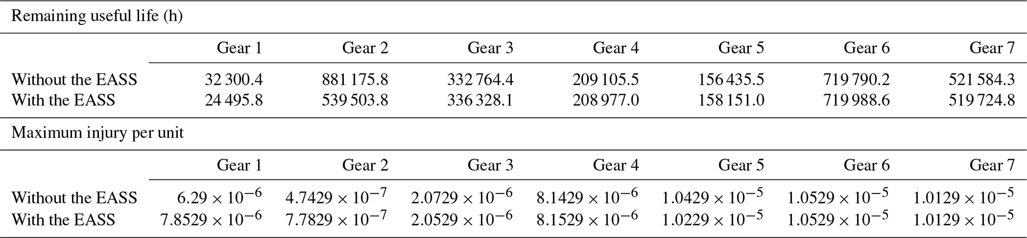
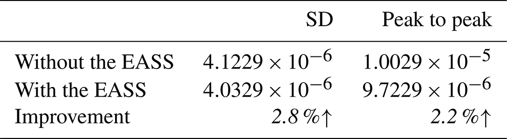
Table 2 shows the maximum injury taken by each gear as assessed after the cycle. The “remaining useful life” was then calculated from these data. Table 3 shows that the peak injury to each gear was reduced by 2.2 %, with the standard deviation reduced by 2.8 %. The injury tended to be consistent, and the performance and reliability of the transmission are improved.
5.3.2 Real-vehicle test
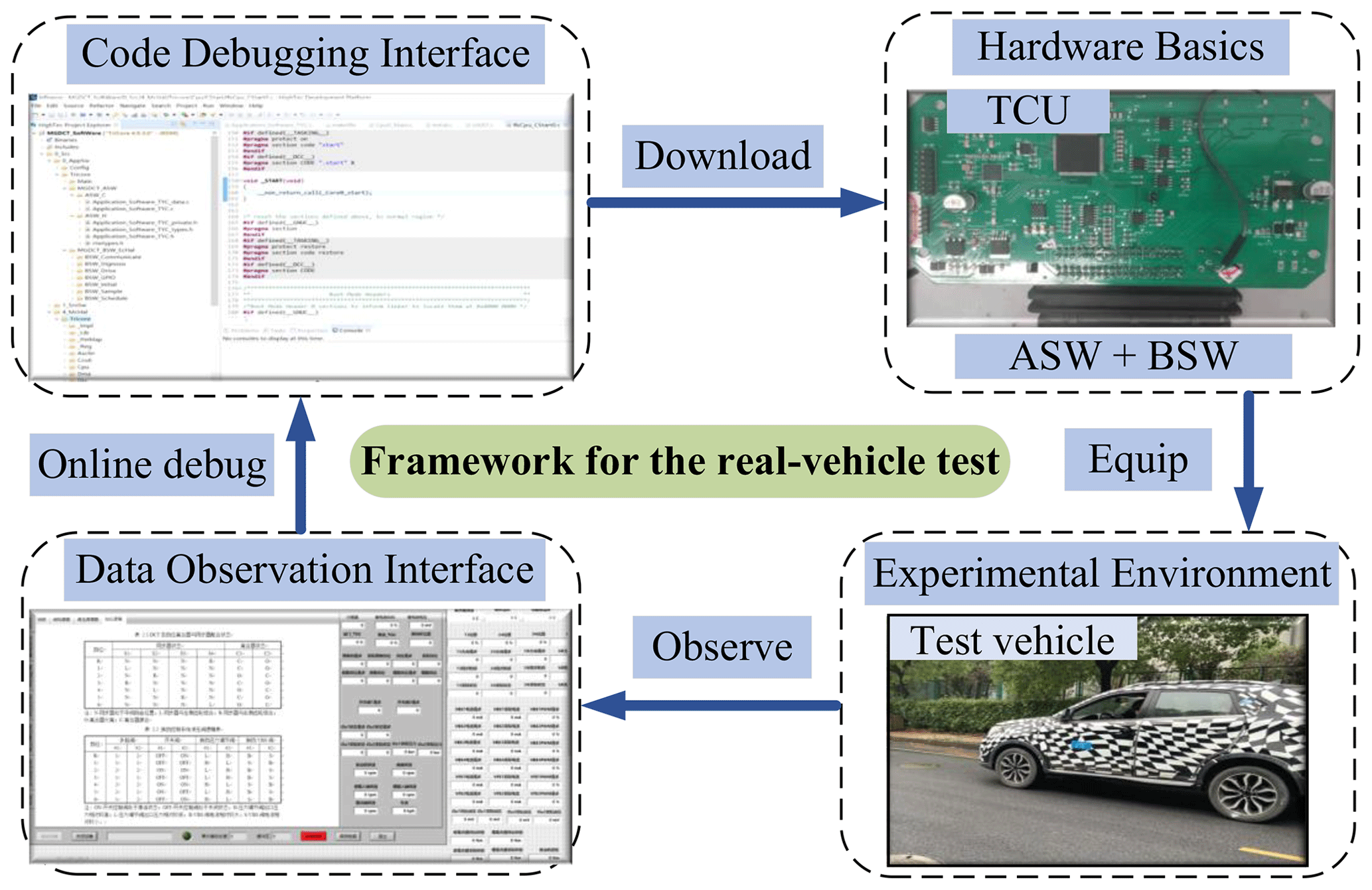
In the real-vehicle verification, the ASW, the Basic SoftWare (BSW), and the hardware developed by the researchers' laboratory for DCT were used as controller carriers. An experimental vehicle equipped with DCT was then used for verification. Figure 15 shows the experimental vehicle and the controller developed for it, with the initial condition of maximum injury for gear 3.
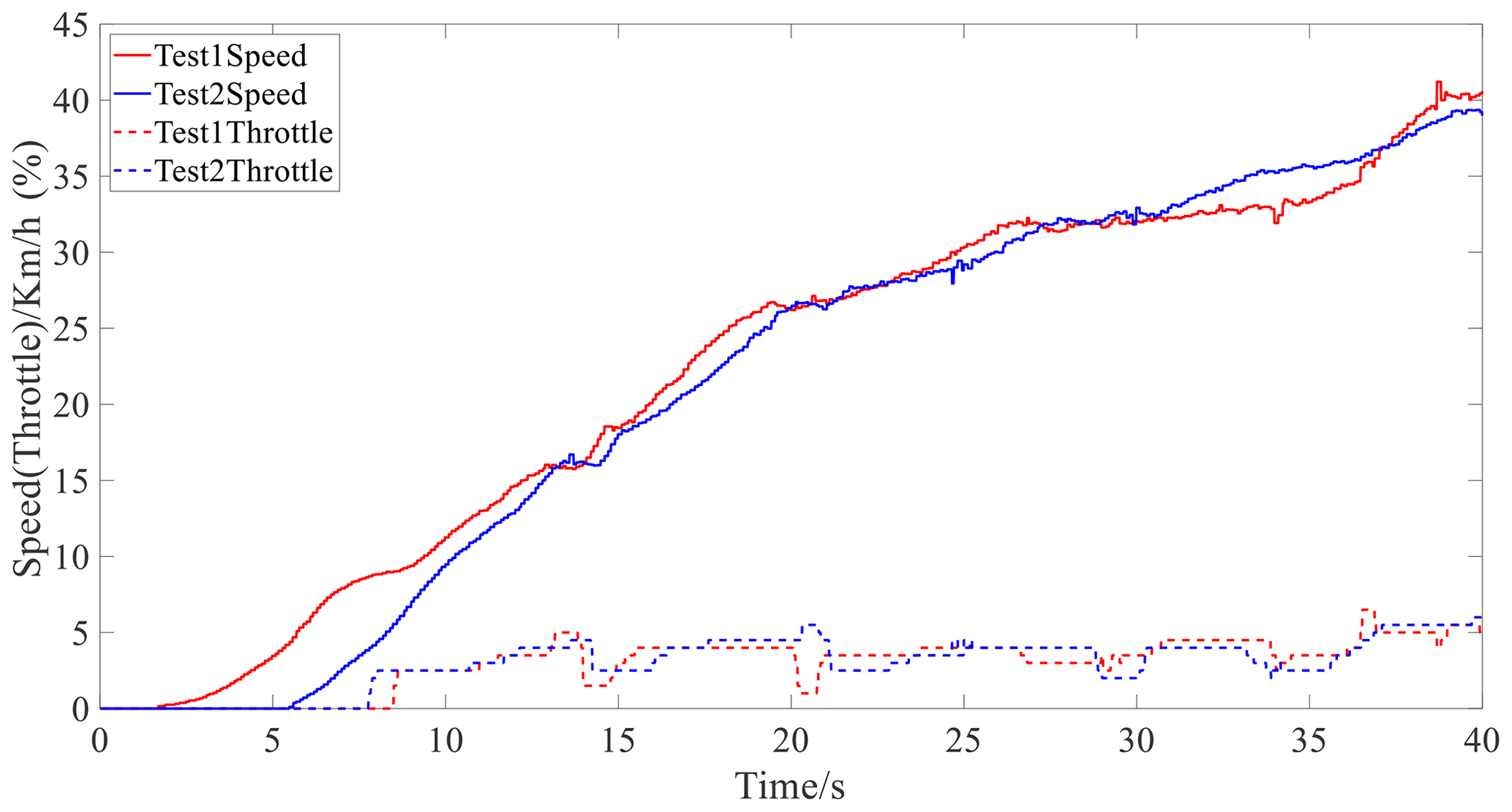
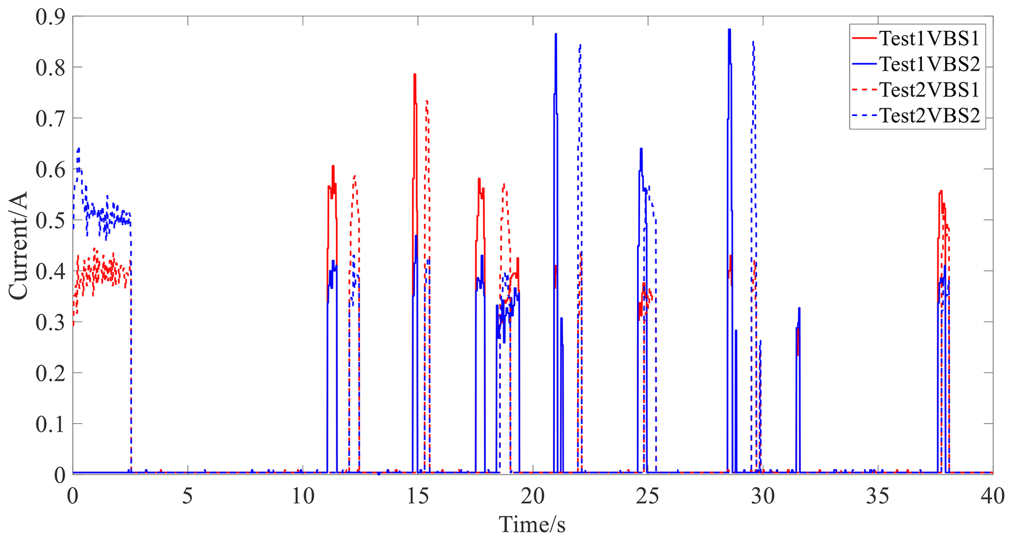
Figure 16 shows the speed and throttle opening results for the real-vehicle experiment. Figure 17 illustrates the control current of the VBS.
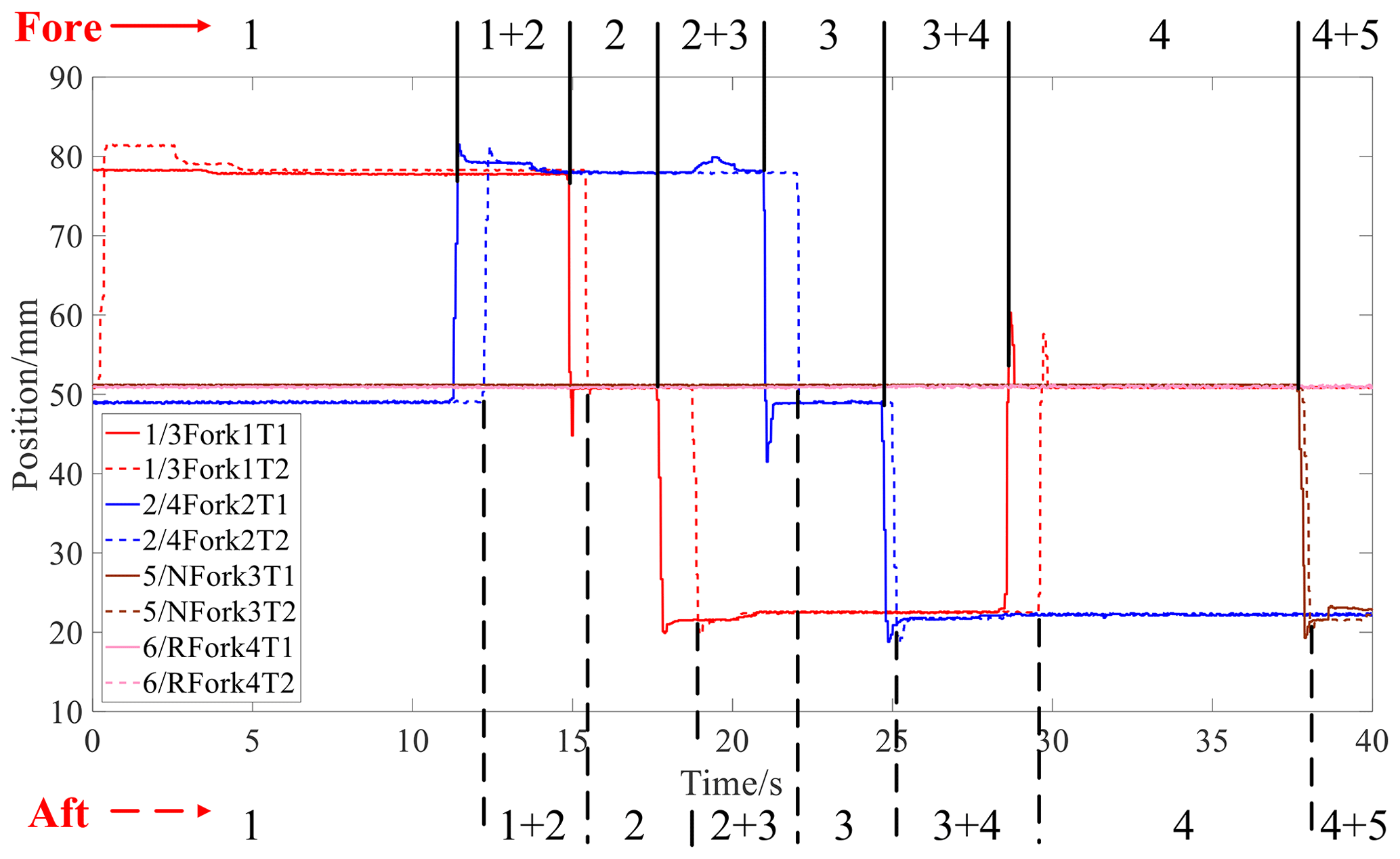
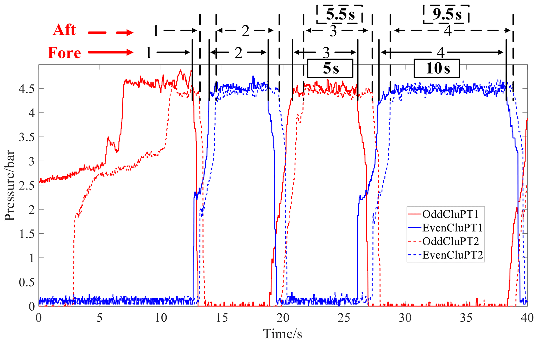
Figures 18 and 19 represent the gear logic diagram and the clutch oil pressure, respectively.
The results show that the proposed strategy intelligently determined that the minimum injury value was gear 4 adjacent to gear 3, and it thus reduced the usage time of gear 3 by upshifting to gear 4 in advance. Therefore, the injury of gear 3 was reduced. As shown in Fig. 19, the working time of gear 4 was thus increased by 5.3 % from 9.5 to 10 s, while the working time of gear 3 was reduced by 9 % from 5.5 to 5 s. This avoided the problem of unbalanced injury across gears that affects the remaining useful life of the transmission overall, thus improving the reliability of the transmission.
This paper proposed a gear injury equilibrium oriented self-adjusted shifting strategy (EASS) to equalize the injury values across gears to ensure consistency alongside a novel control algorithm for synchronizer systems based on an adaptive nonsingular global fast-terminal sliding-mode control (AN-GFTSMC), with the latter designed to improve the response performance of the synchronizer.
The EASS judges the gear with the largest injury value in real time and, by adjusting the shift curve, ensures that the gear is then subject to shorter working times, while those adjacent gears with less injury are assigned longer working times. The EASS thus prolongs the overall service life of the transmission and provides the basis for directional lightweight design in such transmission. By considering various key points as constraints, an optimal displacement trajectory for the synchronizer was then proposed, and an AN-GFTSMC algorithm, which reduces the response time of the synchronizer hydraulic system, was presented. The AN-GFTSMC reduced the working time and enlarged the peak velocity during the synchronizer working process, offering improved response performance and ride comfort. Both the simulated and real-vehicle experimental results showed that, as compared with conventional control, the overall improvement in the synchronizer operation time was 43.3 %, while the peak velocity improvement in the sleeve indexation to synchronization stage increased 5.23 times, in the ring deviation + free-flying stage this was 3.88 times, and in the gear deviation + lock-up stage it was 2.9 times. There was no impact during the whole process. The peak value of gear injury decreased by 2.2 %, with the standard deviation also decreasing by 2.8 %. The working time of the gear with the maximum injury value decreased by 9 %, while the working time of the adjacent gear with a smaller injury value increased by 5.3 %.
By applying the proposed EASS strategy, the ongoing injury of gears was more consistent, effectively avoiding focused injury on a single gear in the transmission while allowing other gears to take relatively small amounts of injury, thus affecting the transmission lifecycle. This method designs the EASS to compare the injury values of different gears in real time, adjust the gear in a timely manner, and make the injury values of each gear consistent. Design the optimal trajectory of the synchronizer, design the AN-GFTSMC algorithm to enable the synchronizer to accurately track the optimal trajectory, effectively reduce the impact during the shifting process, improve the shifting speed, and effectively guide the lightweight design of the transmission. The experimental results verified the effectiveness of the proposed strategy. In particular, the results indicated that the proposed method offers better performance with respect to synchronizer control than traditional methods. The application range and limitation of the method are that it is only suitable for mechanisms with gearboxes such as vehicle transmissions and wind turbine gearboxes.
| Symbols and abbreviations | Full name |
| EASS | Gear injury equilibrium oriented |
| self-adjusted shifting strategy | |
| AN-GFTSMC | Adaptive nonsingular global |
| fast-terminal sliding-mode | |
| control | |
| Gear i | GiD represents the injury value |
| of the ith gear | |
| HAS | Hydraulic actuation system |
| VBS | Variable-bleed solenoid |
| ASW | Application SoftWare |
| BSW | Basic SoftWare |
| NEDC | New European Driving Cycle |
| SD | Standard deviation |
| DCT | Dual-clutch transmission |
Code and data are available on reasonable request.
ZL: data curation and investigation; methodology; resources; software validation; writing – original draft preparation. GW: conceptualization; funding acquisition; methodology; project administration and supervision. QW: formal analysis and investigation; software visualization; writing – review and editing. HY: software.
The contact author has declared that none of the authors has any competing interests.
Publisher’s note: Copernicus Publications remains neutral with regard to jurisdictional claims made in the text, published maps, institutional affiliations, or any other geographical representation in this paper. While Copernicus Publications makes every effort to include appropriate place names, the final responsibility lies with the authors.
This work has been supported by the National Key Research and Development (R&D) Program of China under grant no. 2021YFB2500800.
This research has been supported by the National Key Research and Development Program of China (grant no. 2021YFB2500803).
This paper was edited by Jinguo Liu and reviewed by two anonymous referees.
Anh. Tuan, V. and Kang, H. J.: A New Finite Time Control Solution for Robotic Manipulators Based on Nonsingular Fast Terminal Sliding Variables and the Adaptive Super-Twisting Scheme, J. Comput. Nonlinear Dyn. 14, 031002, https://doi.org/10.1115/1.4042293, 2019.
Barathiraja, K., Jamadade, G., Rakesh, S., and Jibin, P. K.: Automotive Gearbox Synchronizer Life Evaluation Using Regression Analysis under Torsional Vibration Condition, SAE 2021 17th Symposium on International Automotive Technology(SIAT), Online, India, CA, 29 Sept–1 Oct, 2021-26-0494, https://doi.org/10.4271/2021-26-0494, 2021.
Bhardwaj, U., Teixeira, A. P., and Soares, C. G.: Reliability Prediction of An Offshore Wind Turbine Gearbox, Renew. Energy, 137, 170–179, https://doi.org/10.1016/j.renene.2019.03.136, 2019.
Boukattaya, M., Mezghani, N., and Damak, T.: Adaptive Nonsingular Fast Terminal Sliding-Mode Control for the Tracking Problem of Uncertain Dynamical Systems, ISA Trans., 77, 1–19, https://doi.org/10.1016/j.isatra.2018.04.007, 2018.
Dhiman, H., Deb, D., Carroll, J., Muresan, V., and Unguresan, M. L.: Wind Turbine Gearbox Condition Monitoring Based on Class of Support Vector Regression Models and Residual Analysis, Sensors, 20, 1–17, https://doi.org/10.3390/s20236742, 2023.
Duc, T. M., Van Hoa, N., and Dao, T. P.: Adaptive Fuzzy Fractional-Order Nonsingular Terminal Sliding Mode Control for A Class of Second-Srder Nonlinear Systems, J. Comput. Nonlinear Dyn., 13, 031004, https://doi.org/10.1115/1.4038642, 2018.
Esser, A., Eichenlaub, T., Schleiffer, J.-E., Jardin, P., and Rinderknecht, S.: Comparative evaluation of powertrain concepts through an eco-impact optimization framework with real driving data, Optimization And Engineering, 22, 1001–1029, https://doi.org/10.1007/s11081-020-09539-2, 2020.
Ghorbani, H., Vatankhah, R., and Farid, M.: Adaptive Nonsingular Fast Terminal Sliding Mode Controller Design for A Smart Flexible Satellite in General Planar Motion, Aerosp. Sci. Technol., 119, 107100, https://doi.org/10.1016/j.ast.2021.107100, 2021.
Hashtarkhani, B. and Khosrowjerdi, M. J.: Neural Adaptive Fault Tolerant Control of Nonlinear Fractional Order Systems Via Terminal Sliding Mode Approach, J. Comput. Nonlinear Dyn., 14, 031009, https://doi.org/10.1115/1.4042141, 2019.
Jiang, L., Xiang, D., Tian, Y. F., Nie, Y. H., Cao, H. J., Wei, Y. H., Zeng, D., Shen, Y. H., and Shen, G.: Analysis of Wind Turbine Gearbox's Environmental Impact Considering Its Reliability, J. Clean Prod., 180, 846–857, https://doi.org/10.1016/j.jclepro.2018.01.078, 2018.
Labbadi, M. and Cherkaoui, M.: Robust Adaptive Nonsingular Fast Terminal Sliding-Mode Tracking Control for An Uncertain Quadrotor UAV Subjected to Disturbances, ISA Trans., 99, 290–304, https://doi.org/10.1016/j.isatra.2019.10.012, 2020.
Li, X. and Yurkovich, S.: Neural Network Based, Discrete Adaptive Sliding Mode Control for Idle Speed Regulation in IC Engines, Trans ASME. J. Dyn. Syst. Meas. Control., 122, 269–275, https://doi.org/10.1115/1.482463, 2000.
Li, Y. Z., Zhou, F., Dong, B., Liu, K. P., and Li, Y. C.: Decentralized Trajectory Tracking Control for Modular and Reconfigurable Robots with Torque Sensor: Adaptive Terminal Sliding Control-Based Approach, Trans ASME. J. Dyn. Syst. Meas. Control., 141, 061003, https://doi.org/10.1115/1.4042550, 2019.
Liu, W., Chen, S. Y., and Huang, H.: Adaptive Nonsingular Fast Terminal Sliding Mode Control for Permanent Magnet Synchronous Motor Based on Disturbance Observer, IEEE Access, 7, 153791–153798, https://doi.org/10.1109/ACCESS.2019.2948945, 2019.
Miao, Y., Hwang, I., Liu, M., and Wang, F.: Adaptive Fast Nonsingular Terminal Sliding Mode Control for Attitude Tracking of Flexible Spacecraft with Rotating Appendage, Aerosp. Sci. Technol., 93, 105312, https://doi.org/10.1016/j.ast.2019.105312, 2019.
Mustafa, G. I. Y., Wang, H., and Tian, Y.: Optimized Fast Terminal Sliding Mode Control for a Half-Car Active Suspension Systems, Int. J. Automot. Technol., 21, 805–812, https://doi.org/10.1007/s12239-020-0078-8, 2020.
Nguyen, V. T., Su, S. F., and Nguyen, A. T.: Adaptive Nonsingular Fast Terminal Sliding Mode Tracking Control for Parallel Manipulators with Uncertainties, 2019 International Conference on System Science and Engineering (ICSSE), Dong Hoi, Vietnam, CA, 20–21 July, 522–525, https://doi.org/10.1109/ICSSE.2019.8823137, 2019.
Qi, R., Su, W., and Meng, Y.: Fault-Tolerant Attitude Controller Design for Deep Space Probe via Adaptive Fast Terminal Sliding Mode Control, Trans ASME, J. Dyn. Syst. Meas. Control., 141, 091006, https://doi.org/10.1115/1.4042548, 2019.
Rabiee, H., Ataei, M., and Ekramian, M.: Continuous Nonsingular Terminal Sliding Mode Control Based on Adaptive Sliding Mode Disturbance Observer for Uncertain Nonlinear Systems, Automatica, 109, 108515, https://doi.org/10.1016/j.automatica.2019.108515, 2019.
Rodriguez, J., Castañeda, H., Gonzalez-Garcia, A., and Gordillo, J. L.: Finite-Time Control for An Unmanned Surface Vehicle Based on Adaptive Sliding Mode Strategy, Ocean Eng., 254, 111255, https://doi.org/10.1016/j.oceaneng.2022.111255, 2022.
Shen, Y., Wu, G. Q., and Luo, X. Y.: Precise Tracking Control of AMT Electric Shift Actuator, Automobile Technology, 01, 24–28, 2014.
Sun, Z., Hu, S., He, D. F., Zhu, W., Xie, H., and Zheng, J. C.: Trajectory-Tracking Control of Mecanum-Wheeled Omnidirectional Mobile Robots Using Adaptive Integral Terminal Sliding Mode, Comput. Electr. Eng., 96, 107500, https://doi.org/10.1016/j.compeleceng.2021.107500, 2021.
V. L. J. Basoalto, H. and Papaelias, M.: A Damage Mechanics Approach for Lifetime Estimation of Wind Turbine Gearbox Materials, Int. J. Fatigue, 137, 170–179, https://doi.org/10.1016/j.ijfatigue.2020.105671, 2020.
Walker, P. D. and Zhang, N.: Transmission of Engine Harmonics to Synchronizer Mechanisms in Dual Clutch Transmissions, ASME Trans. J. Vib. Acoust., 136, 051009, https://doi.org/10.1115/1.4028079, 2014.
Walker, P. D., Fang, Y. H., and Zhang, N.: Dynamics and Control of Clutchless Automated Manual Transmissions for Electric Vehicles, ASME Trans. J. Vib. Acoust. 139, 061005, https://doi.org/10.1115/1.4036928, 2017.
Wang, D., Miao, Q., Zhou, Q. H., and Zhou, G. W.: An Intelligent Prognostic System for Gear Performance Degradation Assessment and Remaining Useful Life Estimation, ASME Trans. J. Vib. Acoust., 137.2, 021004, https://doi.org/10.1115/1.4028833, 2015.
Wang, N. and Hao. F.: Event-Triggered Sliding Mode Control with Adaptive Neural Networks for Uncertain Nonlinear Systems, Neurocomputing, 436, 184–197, https://doi.org/10.1016/j.neucom.2021.01.055, 2021.
Wu, G.: Automotive Digital Development Technology, 1st Edn., China Machine Press, Beijing, China, Chap. 2, ISBN 978-7-111-28308-9, 2010.
Wu, G. Q. and Si, J. Y.: Research of Eliminating Method of Undesired Shifting for Vehicle with Dual Clutch Transmission, SAE Technical Paper Series, 2013-01-0485, https://doi.org/10.4271/2013-01-0485, 2013.
Wu, G., Lyu, Z., and Wang, C.: Predictive Shift Strategy of Dual-Clutch Transmission for Driving Safety on the Curve Road Combined with an Electronic Map, SAE Int. J. Veh. Dyn., Stab., and NVH 7,1, 1–19, https://doi.org/10.4271/10-07-01-0001, 2023.
Xia, H., Sheng, Q., and Wei, H.: Influence of Gear-Shaft-Bearing Configurations on Vibration Characteristics of Spiral Bevel Gear Drives, SAE Int. J. Veh. Dyn., Stab., and NVH 4,3, 275–289, https://doi.org/10.4271/10-04-03-0019. 2020.
Yan, Y., Zhao, X., Yu, S., and Wang, C. L.: Barrier Function-Based Adaptive Neural Network Sliding Mode Control of Autonomous Surface Vehicles, Ocean Eng. 238, 109684, https://doi.org/10.1016/j.oceaneng.2021.109684, 2021.
Yang, W. B., Chen, Q. S., Wu, G. Q., and Qin, D. T.: The synchronizer control strategy for dual clutch automatic transmission based on city drive cycle, Chin. J. Mech. Eng., 44, 244–248, https://doi.org/10.3901/JME.2008.12.244, 2008.
Yi, S. and Zhai, J.: Adaptive Second-Order Fast Nonsingular Terminal Sliding Mode Control for Robotic Manipulators, ISA Trans., 90, 41–51, https://doi.org/10.1016/j.isatra.2018.12.046, 2019.
Zhuang, H., Sun, Q., Chen, Z., and Zeng, X. Y.: Robust Adaptive Sliding Mode Attitude Control for Aircraft Systems Based on Back-Stepping Method, Aerosp. Sci. Technol., 118, 107069, https://doi.org/10.1016/j.ast.2021.107069, 2021.
- Abstract
- Introduction
- Gear injury equilibrium oriented self-adjusted shifting strategy
- Synchronizer modeling
- AN-GFTSMC design
- Verification and analysis
- Conclusions
- Appendix A: Symbols and abbreviations used in this paper
- Code and data availability
- Author contributions
- Competing interests
- Disclaimer
- Acknowledgements
- Financial support
- Review statement
- References