the Creative Commons Attribution 4.0 License.
the Creative Commons Attribution 4.0 License.
 | 31 Aug 2023
A vision-based robotic system following the human upper-limb sewing action
Liming Zhang
Xiaohua Wang
Haoyi Wang
Pengfei Li
In human–robot collaborative sewing, the robot follows the sewing action of a worker to complete the corresponding sewing action, which can enhance production efficiency. When the robot follows the sewing action of the worker through interactive information, it still faces the problem of low accuracy. In order to improve the accuracy of the robot following the sewing action, a human upper-limb sewing-action-following system based on visual information is designed in this paper. The system is composed of an improved OpenPose model, Gaussian mixture model (GMM), and Gaussian mixture regression (GMR). In the system, an improved OpenPose model is used to identify the sewing action of the human upper limb, and the label fusion method is used to correct the joint point labels when the upper limb is covered by fabric. Then the GMM is used to encode each motion element and time to obtain the regression work of the Gaussian component. GMR is adopted to predict connections between moving elements and generate sewing motion trajectories. Finally, the experimental verification and simulation are carried out in the experimental platform and simulation environment of the collaborative robot. The experimental results show that the tracking error angle can be controlled within 0.04 rad in the first 2 s of robot movement. Therefore, it can be considered that the sewing-action-following system can realize higher precision and promote the development of human–robot collaboration technology to a certain extent.
- Article
(5904 KB) - Full-text XML
- BibTeX
- EndNote


Human–robot collaboration technology is an important development direction in the field of intelligent robots (He et al., 2017; Baraglia et al., 2017; Ajoudani et al., 2018). The programming method of collaborative robots usually uses artificial teaching (Yanagihara et al., 2001) or offline programming (Žlajpah, 2008). The above two programming methods have operators with greater technical experience, and robots can only repeat their actions according to the fixed trajectory. In the sewing factory, in order to cooperate with the worker efficiently, the collaborative robot needs to understand the sewing intention of the worker (Lang et al., 2022). By learning the sewing action of the worker, the collaborative robot can follow the action of the human upper limb, acquiring the corresponding sewing skills.
With the development of human–robot collaboration technology, many simpler and efficient collaborative robot programming methods have been developed. The most direct method for robots to follow people is through kinesthetic teaching (Wrede et al., 2013). This involves the robot being manually dragged by people to teach and record its movement. Kinesthetic teaching does not require additional equipment and is easy to operate (Kronander and Billard, 2013; Billard et al., 2016). Kim et al. (2016) used three different kinesthetic teaching methods, namely joint-level, task-level, and contact-level teaching. They programmed the task into the dual-arm robot to guide the dual-arm robot to complete a packing task in an industrial environment. Fan et al. (2019) designed and developed a teaching manipulator with 6 degrees of freedom in order to facilitate the setting and recording of motion trajectories of industrial robots. However, this teaching method is usually only applicable to light manipulators with low inertia, which is difficult for robots with multiple degrees of freedom, and robots can only perform tasks in a fixed environment.
In order to achieve intelligent human–robot collaboration, researchers began to allow robots to use visual recognition to obtain human–robot interaction information. Schenck et al. (2017) used deep learning methods to establish a worker’s action prediction model and sent the prediction results to the robot. Then the robot performed corresponding operations such as digging and dumping granular media. The Google Brain research institute (Gu et al., 2016) used a Deep Q-Network to recognize the grasping action of the human arm and converted the captured image of the arm grasping action into the corresponding features of the grasping action to complete the robot’s assistance crawl.
After the collaborative robot obtains information on the teaching action through visual information, the skill learning method can actively follow people's actions. Khansari-Zadeh and Billard (2011) used a Gaussian mixture model (GMM) to model the teaching trajectory probabilistically, calculated the model parameters through Gaussian mixture regression (GMR) iteratively until convergence, and predicted the next movement trajectory. Ijspeert et al. (2013) used a dynamical movement primitive (DMP) to follow the teaching action of the robot. By iteratively updating the motion parameters between the trajectory points, the motion information for a single teaching trajectory was learned. The learning results were generalized to the complete motion process of the robot. Ravichandar and Dani (2019) transformed the action-following problem into a steady-state system problem. This is based on the Stable Estimator of Dynamical Systems (SEDS) theory, which has the ability to generalize the motion trajectory point to any target position. However, both DMP and SEDS have similar limitations and cannot directly process and generalize motion trajectory points with temporal attributes. Yunus et al. (2022) proposed a Kalman filter time series human motion prediction algorithm. The algorithm updated the Kalman gain parameter of the trajectory data to realize the prediction and the following of the human action trajectory.
To realize the sewing action of the human upper limb, a following method for the robot – OpenPose and GMM–GMR (OGG) – is proposed in this paper. OGG is designed to observe a worker's sewing action and realize the following of this sewing action. The specific methods of this paper are as follows:
-
The OpenPose model is built to identify the motion trajectory of human upper-limb joints. The joint localization problem in fabric occlusion is solved by the tag fusion method.
-
The GMM is used to encode the action trajectory obtained by the deep neural network with the time factor to obtain motion elements, and GMR is applied to calculate the mean function and variance function of each motion element. Then the obtained Gaussian regression functions are mixed and weighted to perform trajectory regression prediction. The trajectory information for the sewing action is learned by storing the conditional expected value and variance of trajectory parameters.
-
The trajectory information for the learned sewing action is transmitted to the robotic arm, which starts to move according to the trajectory information.
The structure of the paper is arranged as follows. The overview of the framework will be discussed in the next section. Section 3 shows the sewing action recognition method, and Sect. 4 introduces the sewing-action-following method. Finally, Sect. 5 presents the simulation and physical platform experimental environment and results.
On the robot platform, our following system used to use the visual servo method. However, we found some disadvantages, and we designed a new system that acted with OGG. As shown in Fig. 1, the robot system based on the visual servo method uses original visual features to extract human image features, maps them to the robot joint angles, performs visual servo control, and realizes the tracking of workers' sewing actions. Due to inaccurate features and robot system errors, the error in the robot's following action is large.
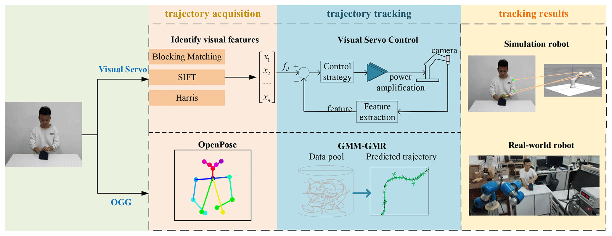
Figure 1The comparison of the OGG method and visual servo method in the trajectory acquisition and trajectory tracking.
In the OGG method, we made improvements in trajectory acquisition and trajectory tracking. The previous method of trajectory acquisition is to identify visual features to obtain key point information, but the OGG method uses OpenPose to obtain the joint point coordinate information on the human body. The previous method used in trajectory tracking is a visual servo, a control method using feedback, while the GMM–GMR method is used in this paper. The robot generates the following motion trajectory corresponding to each joint according to the trajectory prediction result, so that the robot can follow the sewing action of the human body upper limb. Finally, we verify the feasibility and stationarity of our method using both simulation and real-world robots.
The motion information in the worker's sewing action is reflected to the joint trajectory. Learning to accurately locate the shoulder, elbow, and wrist joints in the worker's sewing action video sequence and to obtain the joint trajectory is key for the robot to follow the sewing action. In fabric turnover and other actions, due to the problem of workers' habitual actions, some upper limbs or hands are often covered by fabric, and the joint positioning will fail. This paper, which uses the label fusion method to correct the joint point label, improves the OpenPose model and obtains the complete joint information for workers in sewing.
3.1 Joint positioning
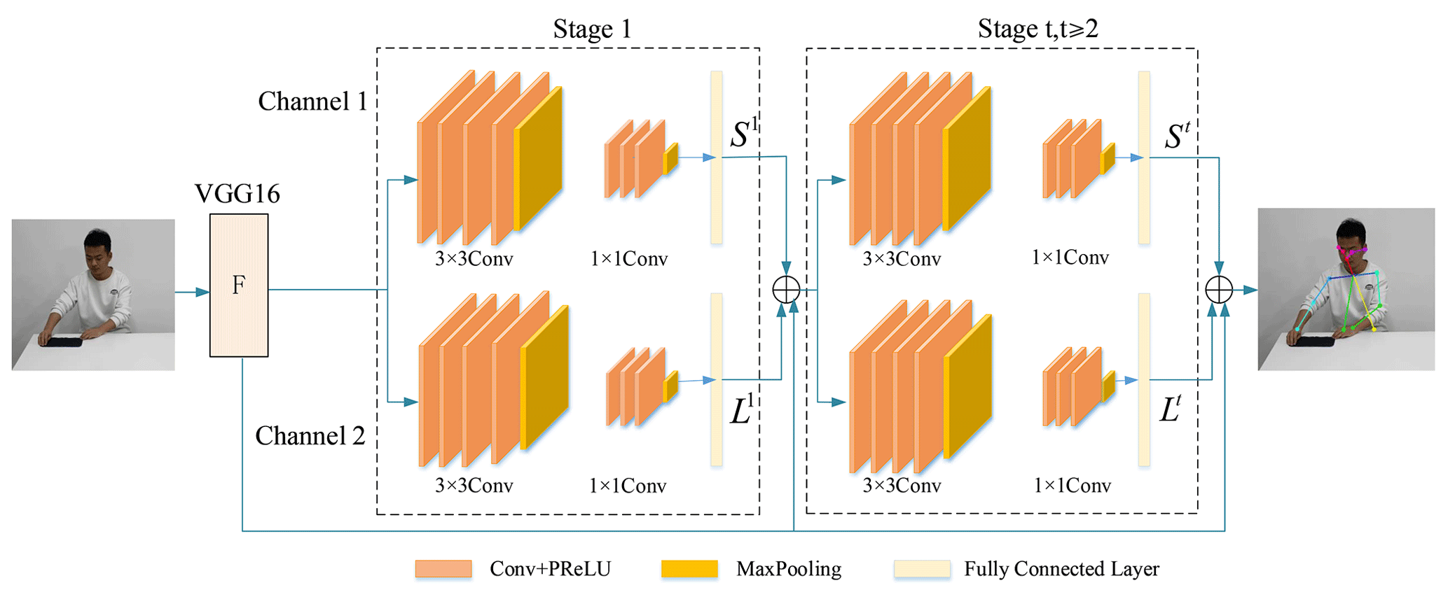
The OpenPose model adopts a VGG-16 deep learning network and dual-channel CNN residual network structure (Ye et al., 2022). Figure 2 shows the structure of OpenPose. The first 10 layers of VGG-16 obtain the original feature maps F of the action image and then connect three 3×3 convolution kernels, which extract deep feature information and spatial texture information while retaining some shallow information, where max pooling uses 1×1 convolution kernels, which make the network deeper to extract higher-level features. Experiments show that the six stages can make the model converge as quickly as possible without overfitting. The output of each stage is sent to the next stage together with the feature of several sub-networks. The convolution part of each stage is a residual network structure composed of a feature map for operation, and the joint positioning results are output after six stages.
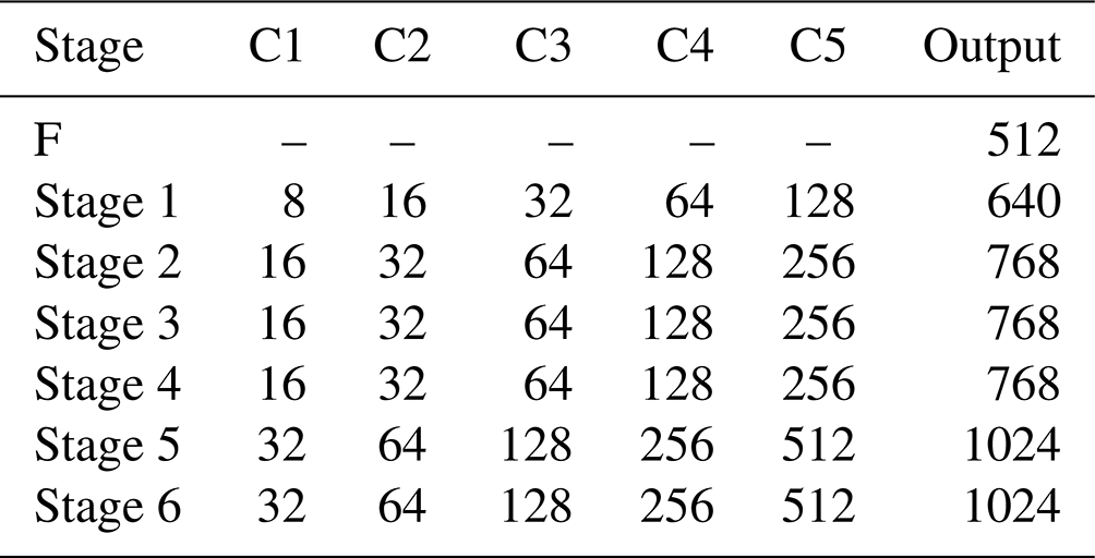
The OpenPose model structure is introduced as shown in Table 1. C1–C5 represent the number of convolution kernels of each convolutional layer in a single channel. F represents the feature map part of the direct output. Stage 1–Stage 6 represent the six stages of the dual-channel CNN structure.
Table 1The OpenPose model structure convolution kernel number.
The two CNN channels of the OpenPose model predict the position of joints and limbs, respectively. Channel 1 predicts the position of the joint points, which is represented by the size of the part confidence maps (PCMs). The confidence value is the Gaussian response of the pixel from the joint point, and the closer the pixel to the joint point, the larger the response value. The non-maximum suppression (NMS) algorithm is used to obtain the peak value of all Gaussian responses as the network output at this stage, which is recorded as S1; Channel 2 predicts part affinity fields (PAFs) of joint points. The PAF represents the position of the limb and the direction of the pixels on the limb, which is recorded as L1. If the pixel is outside the limb, the PAF is 0; if the pixel is on the limb, the PAF between xj1 and xj2 is .
After six stages of network training, the position information on all joint points and the direction vector of connected joint points are obtained. When the greedy reasoning algorithm is used to connect joint limbs and the total affinity between the two joint points is calculated iteratively to the maximum, the loss function of the model converges and the skeleton connection between the joint limbs can be obtained. The loss functions of channels 1 and 2 at Stage t are expressed as and . The loss function is calculated in Eq. (1).
Here, J and C represent the quantity of S and L, respectively. For a joint point p, if the label of p is missing, W(p) is 0, and the loss function does not calculate this point; if W(p) is 1, it means that the label of p is successful, and the loss function of the point is calculated. is the L2 norm between the predicted value St and the ground truth (GT) S*, and is the same. represents the key tag of model training. The total loss function is the sum of the loss function of each sub-stage network, as shown in Eq. (2):
3.2 Improved OpenPose model
In order to solve the problem of joint positioning failure caused by the shielding of some upper limbs by fabric, this paper corrects the joint point label by label fusion and improves the loss function of OpenPose in the process of calculating the loss function of the model (Kato et al., 2018). The original model is used to generate labels for the data set . The label that was marked when the model was trained () was combined with PT to get a new label () as a label for the current model training. The calculation formula for the new label is given by
and the loss function after label correction is
In order to verify the effectiveness of the improved model, a comparative experiment on human motion recognition is carried out. The COCO human skeleton frame data set is used for model training, and mean average precision (MAP) is used as the accuracy evaluation index to represent the average positioning accuracy of all joint points; FPS (frames per second) is used as the time evaluation index to represent the number of picture frames tested per second. Table 2 presents the comparison results.
Table 2Comparison of the results of different models on the COCO human body data set.
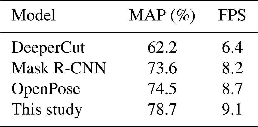
It can be seen from Table 2 that compared with DeeperCut, the accuracy of this method is improved by 16.5 percentage points and FPS is improved by 2.7. Compared with Mask R-CNN, the accuracy is improved by 5.1 percentage points and FPS is improved by 0.3. Compared with OpenPose, the accuracy is improved by 4.2 percentage points and FPS is improved by 0.4. Figure 2 shows the recognition results of human upper-limb joints before and after improvement.
Figure 3 shows that the improved model can correct the joint point label, reposition the right wrist joint, establish the limb connection with the right elbow joint, and successfully identify the right arm of the human body.
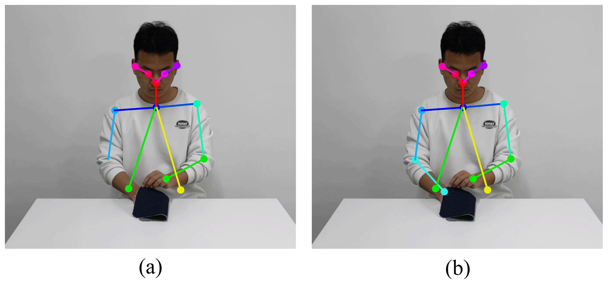
Figure 3Comparison chart of the recognition effect of the improved model. (a) Before improvement. (b) After improvement.
The obtained coordinates of upper-limb joints of the worker's sewing action are taken as training samples. We considered the time factor for the clustering process on the nodes of the training samples, and GMM mixed coding is used on the clustering nodes. The expectation maximization (EM) algorithm is adopted to cluster the model parameters, so as to maximize the probability of the model based on historical data. Clusters representing Gaussian components are obtained, and each cluster represents a joint. So the worker's sewing action is composed of motion. GMR is used to predict the motion of joint training, and the conditional expected value and variance of the model are constantly updated according to the prediction error. The expected value and variance become the parameters of motion learning.
4.1 GMM sewing motion mixed coding
In order to enable the robot to simultaneously learn the joint motion information and the corresponding time information, the GMM is used to encode the obtained sewing motion trajectory (Xie et al., 2017). The sewing action of the worker's upper limb contains the motion trajectory information on shoulder, elbow, and wrist joints. The same period t(t=1000 ms) is used to divide the motion trajectory of each joint into several motion elements, each of which represents a sub-process of the sewing action of a joint. The GMM Ω is established to carry out mixed coding for each segment-of-motion element, and each element is represented by seven dimensions: a one-dimensional timestamp t and a six-dimensional joint posture of the robot . In order to determine the predicted trajectory according to the comparison of different trajectory probabilities, the GMM is used to establish the joint distribution probability density function of N Gaussian components. Each Gaussian component represents a coded motion element:
Here, t and h, respectively, represent the time stamp and joint posture of the motion element in the model Ω, and πn, pn, μn, and ∑n are the prior value, conditional probability density, mean value, and covariance of the nth Gaussian component, respectively.
Firstly, the sewing trajectory data are modeled by probability density function, and the training trajectory data are cluster-analyzed by the GMM. To improve the convergence speed of the algorithm, the k-means algorithm is used for GMM initialization. By using the EM algorithm, the parameters in the probability density function are estimated until convergence. According to the conditional distribution of data conforming to a normal distribution, the regression function of N Gaussian components is obtained, which is used for GMR trajectory prediction learning.
4.2 GMR sewing trajectory prediction
GMR has been used to calculate the mean function and variance function of each moving element, and the N Gaussian regression functions are mixed and weighted to predict the trajectory regression. By updating the conditional expected value and variance in the learning trajectory parameters, the trajectory information on the sewing action is learned, and the trajectory of the robot following the action is generated (Cheng et al., 2021).
In the ith motion element model Ωi, the time value t is used to query the trajectory h of each time step. For a specific time step , the conditional expected value and variance are estimated by GMR for attitude , and the joint probability density function is
Here, represents the mean value corresponding to the kth Gaussian component posture h when the time step is . means that when the time step is and the mean is , the query condition of the nth Gaussian component is the variance corresponding to the attitude h. The same can be obtained for and .
In Eq. (6),
μh,n represents the mean value corresponding to the nth Gaussian component time t and attitude h; and , respectively, indicate that when the mean value is μh,n, the query condition is the variance corresponding to time t and attitude h. The same can be obtained for and .
Then, for a specific step size , the mixing weight of the Nth Gaussian component is employed in the program as
Therefore, the GMR model of the trajectory, that is, the predicted value of the output, is , computed as follows:
The corresponding variance for is
By substituting the learned conditional expected value and variance into Eq. (10), the Gaussian mixture regression function can be weighted and mixed to complete the regression prediction of the sewing trajectory. According to the trajectory prediction results, the robot can generate the following motion trajectory of each joint to realize the learning and tracking of sewing actions.
4.3 GMM weight adjustment
The traditional GMM has poor data processing ability for sewing trajectories on time series, resulting in a lack of smoothness of GMM convergence. Therefore, in this paper, an autoregressive integrated moving average (ARIMA) model is used to process the sewing action trajectory, so that the trajectory data tend to be stable (Ma et al., 2022). Through the error analysis of the ARIMA model, the weight of the GMM is adjusted by weighted fusion.
According to the similarity between the GMM and the ARIMA model, SI(Ri,Rj) is defined, where i≠j. Ri and Rj are the reference of the GMM and the ARIMA model, respectively. shows the reliability difference between different models, and meets the requirements of a normal distribution. The similarity of the two models is shown in Eq. (11). The larger the distance between the reliability analysis results, the smaller the similarity of the two models.
The degree of mutual support in the two models can be expressed as
The mutual support between the results of the two models is the dynamic weight of each model, which is
After the weight adjustment, the probability density function of the joint distribution of n Gaussian components is established using the GMM as follows:
In order to verify the smoothness of the sewing motion track processed by the GMM after weight adjustment, this paper takes the single-motion element of the sewing trajectory as an example, the traditional GMM and the weight-adjusted GMM are used in MATLAB to process the sewing action trajectory, and the GMM smoothness is compared. The results are shown in Fig. 4.
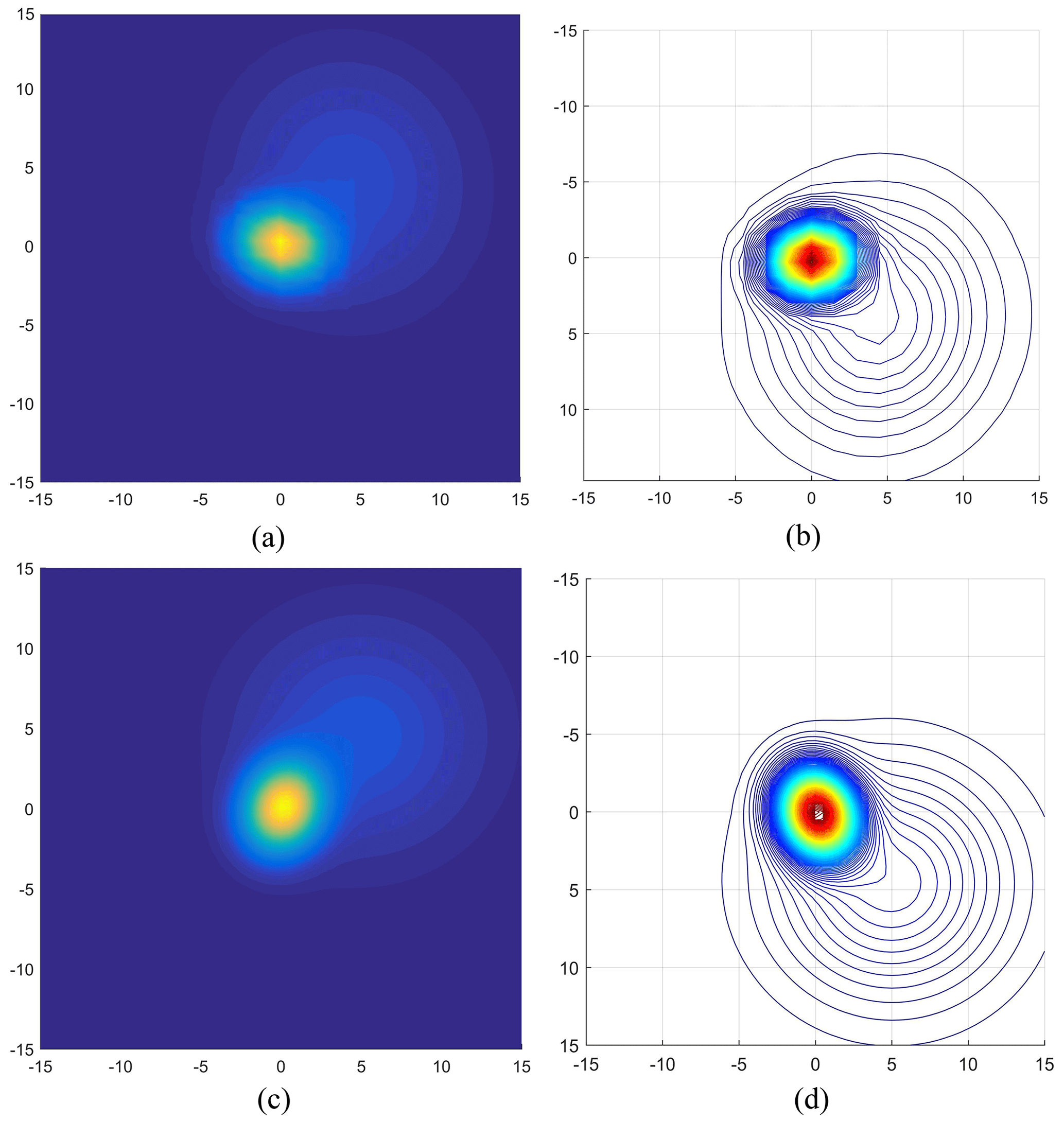
Figure 4The GMM handles the convergence process of kinematic elements. (a–b) Traditional GMM. (c–d) Weight-adjusted GMM.
Figure 4a–b and c–d, respectively, show the model convergence process when the GMM processes a single sewing motion element before and after weight adjustment. When the variance of the GMM is σ2=0.05, the model converges to the position of the red area in Fig. 4b and d. By comparing the convergence process of the GMM in Fig. 4, it is found that the processing of trajectory data by the traditional GMM lacks smoothness and tends to fall into the local extremum in the convergence process. However, the GMM convergence curve after weight adjustment is smoother, and the convergence process is more stable. The model does not easily produce extreme local values, which is conducive to predicting and following the sewing action trajectory of GMR.
In order to verify the following effect of the OGG method, the sewing action recognition experiment, the sewing action learning simulation experiment, the sewing trajectory tracking simulation experiment, and the robot following experiment were carried out. The experimenter showed the sewing action and collected images with an industrial camera. This information on upper-limb action was extracted for the sewing action learning simulation experiment, which demonstrated the feasibility and learning effect of the OGG method. Finally, the stability and application value of the OGG method is verified by the sewing trajectory tracking simulation experiment and the robot following experiment, and the effectiveness is verified by comparing the results with the visual servo system.
5.1 Sewing actions recognition experiment
In the process of sewing, there are often actions such as moving the fabric, allocating the fabric, and turning the fabric. According to these actions, the experimenter conducted three groups of teaching sewing action demonstrations. The size of the fabric was 260×160 mm, and the working radius of the robot with 6 degrees of freedom was 850 mm, which was in line with the working space of the robot.
The improved OpenPose model was used to conduct posture recognition for teaching sewing actions. Figure 5a, b, and c are the recognition results of three groups of teaching sewing actions, respectively. After the recognition is successful, the coordinate changes in the shoulder, elbow, and wrist joints of the human right arm in each action are recorded. The sewing track corresponding to each joint is obtained as the track sample for the robot to learn.
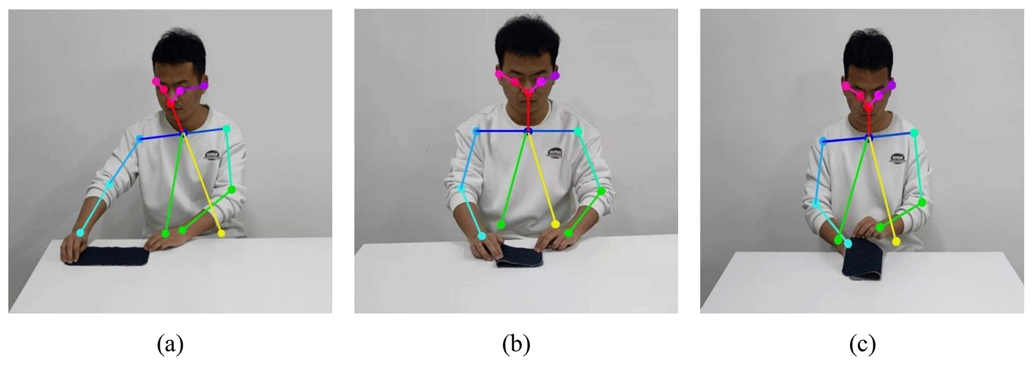
Figure 5Recognition result of teaching sewing motion. (a) Move the fabric. (b) Align the fabric. (c) Flip the fabric.
5.2 Sewing action learning simulation experiment
After the recognition by the OpenPose model is completed, the coordinate changes corresponding to the right arm joint are recorded during the sewing action. The motion tracks of the wrist, elbow, and shoulder of the human right arm are obtained, as shown in Fig. 6, where the yellow, purple, and green curves represent the motion trajectory of the wrist joint, elbow joint, and shoulder joint, respectively. Points A, B, C and A′, B′, C′ are the starting and ending positions of the wrist joint, elbow joint, and shoulder joint, respectively. As can be seen from Fig. 6, when moving fabric, the motion amplitude of the three joints of the right arm is relatively small. When the fabric was aligned, the motion amplitude of the wrist joint in the vertical direction increased significantly. In the process of fabric flipping, the motion amplitude of the three joints in the vertical direction is large, which accords with the kinematic characteristics of the human body in reality.
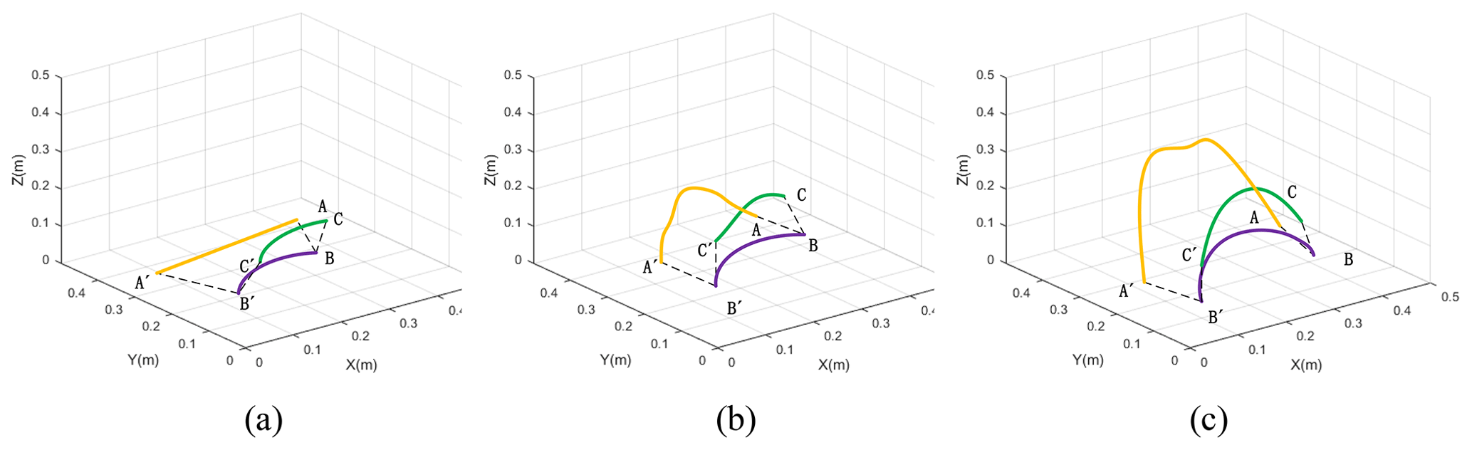
Figure 6Sewing motion trajectory diagram. (a) Move the fabric. (b) Align the fabric. (c) Flip the fabric.
The GMM and GMR are used to encode and learn each complete trajectory. The two-dimensional projection of the learned trajectory is shown in Fig. 7, where each two-dimensional curve represents the learning result of a joint motion trajectory in Fig. 6. Figure 7a corresponds to the motion track of the shoulder joint when moving the fabric, namely the green track in Fig. 6a. Figure 7b corresponds to the wrist motion track when aligning the fabric, namely the yellow track in Fig. 6b. Figure 7c corresponds to the elbow action trajectory when flipping the fabric, which is the purple trajectory in Fig. 6c.
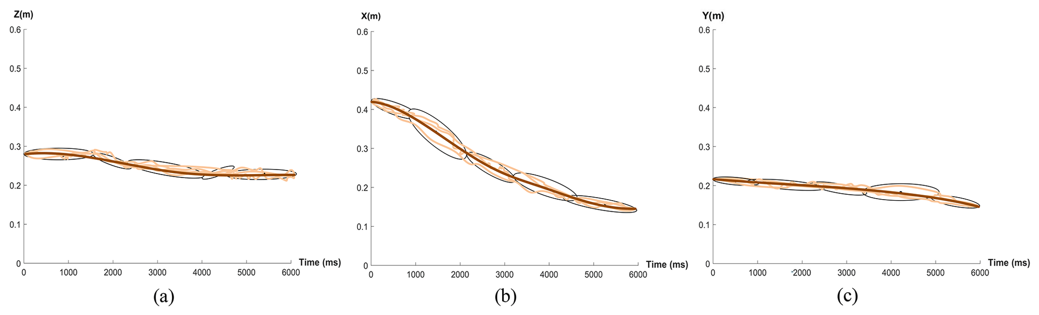
Figure 7Sewing motion trajectory learning results. (a) Move the fabric. (b) Align the fabric. (c) Flip the fabric.
In Fig. 7, the light brown curve represents the training data, black ellipses represent the two-dimensional Gaussian characteristics of motion elements, and the brown line represents the learning path. Elements of the three movements have different characteristics; for example in Fig. 6a, a third of the GMM covariance is , a fourth of the GMM covariance is , the trajectory curve has an inflection point when the variance is bigger, and the trajectory curve is smoother when the variance is small. For the same reason, the variance of the second GMM in Fig. 7b and that of the third GMM in Fig. 7c are both large. The results show that the proposed method can effectively capture the constraint conditions at each motion element and teach the trajectory information for each motion element, so as for the robot to effectively learn the sewing action.
5.3 Sewing trajectory tracking simulation experiment
When the worker moves the fabric, the three joints of the shoulder, elbow, and wrist all move a long distance, which is more conducive to verifying the tracking effect of the sewing motion trajectory compared with aligning the fabric and flipping the fabric. Therefore, this paper takes the motion trajectory of the three joints of the right arm in moving the fabric as an example. We use the simulation model of robot with 6 degrees of freedom built in the Robot Operating System (ROS) to carry out the simulation experiment of robot trajectory tracking.
Input the angle values of the right arm shoulder joint, elbow joint, and wrist joint, respectively, into joints 2, 3, and 4 of the robot simulation model in ROS. Each joint of the robot will move to the desired position, so that the robot can track the teaching sewing track. In this paper, the Kalman prediction method and the GMM–GMR method are used to calculate the joint angle values.
The Kalman prediction method was used to predict the joint angle value in the trajectory interpolation process. The next joint angle value was predicted according to the current joint angle value, and the optimal value was calculated according to the predicted and measured values of the joint angle.
The process of joint angle change using the GMM–GMR method is shown in Fig. 8a–f. The robot model in the Gazebo physical simulation platform follows the sewing motion trajectory according to the received expected joint angle and broadcasts the status of each joint to monitor the robot model joints 2, 3, and 4 in real time in the terminal. The arc of motion changes.
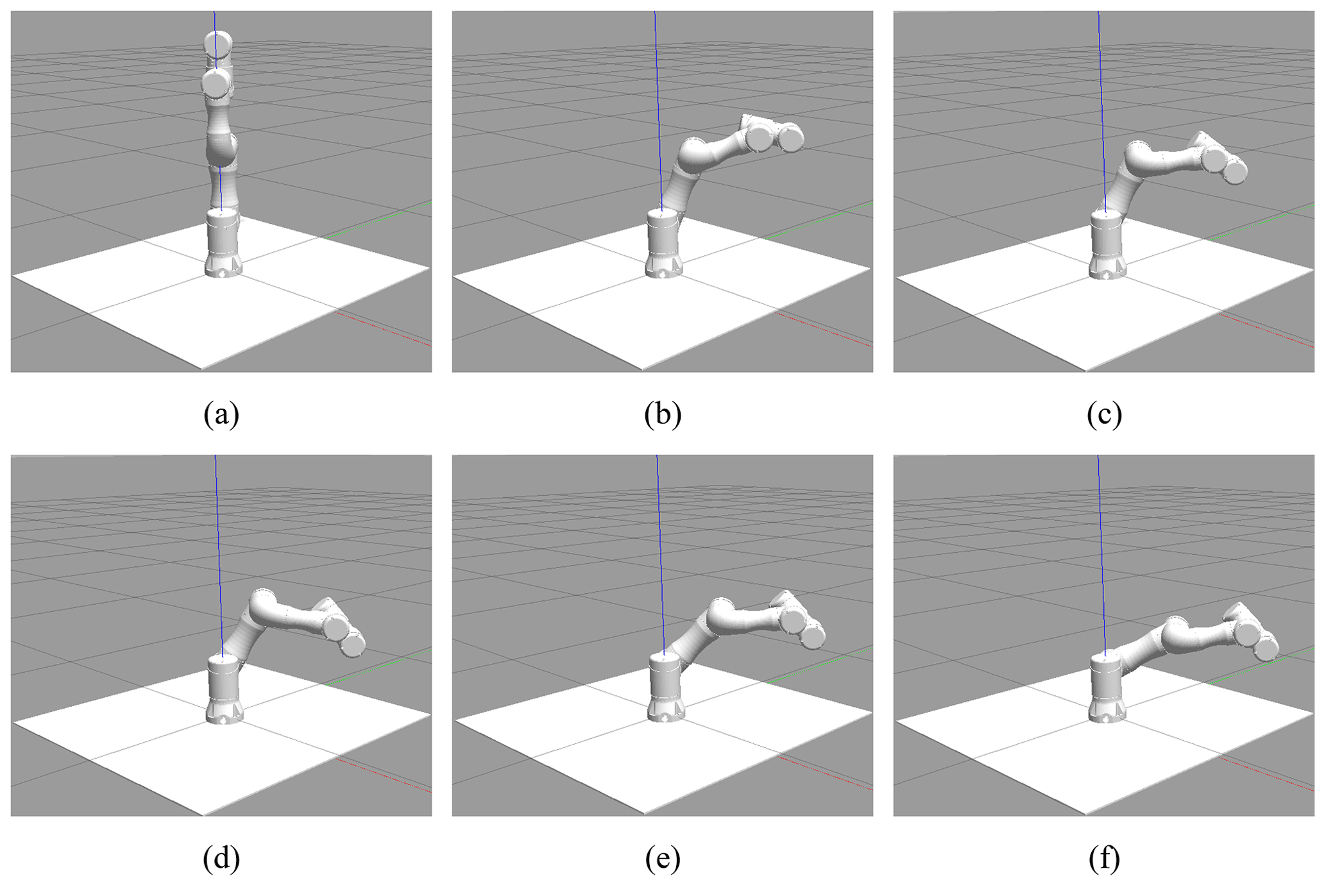
Figure 9 shows trajectory tracking curves and corresponding error curves of joints 2, 3, and 4 in the process of robot motion tracking.
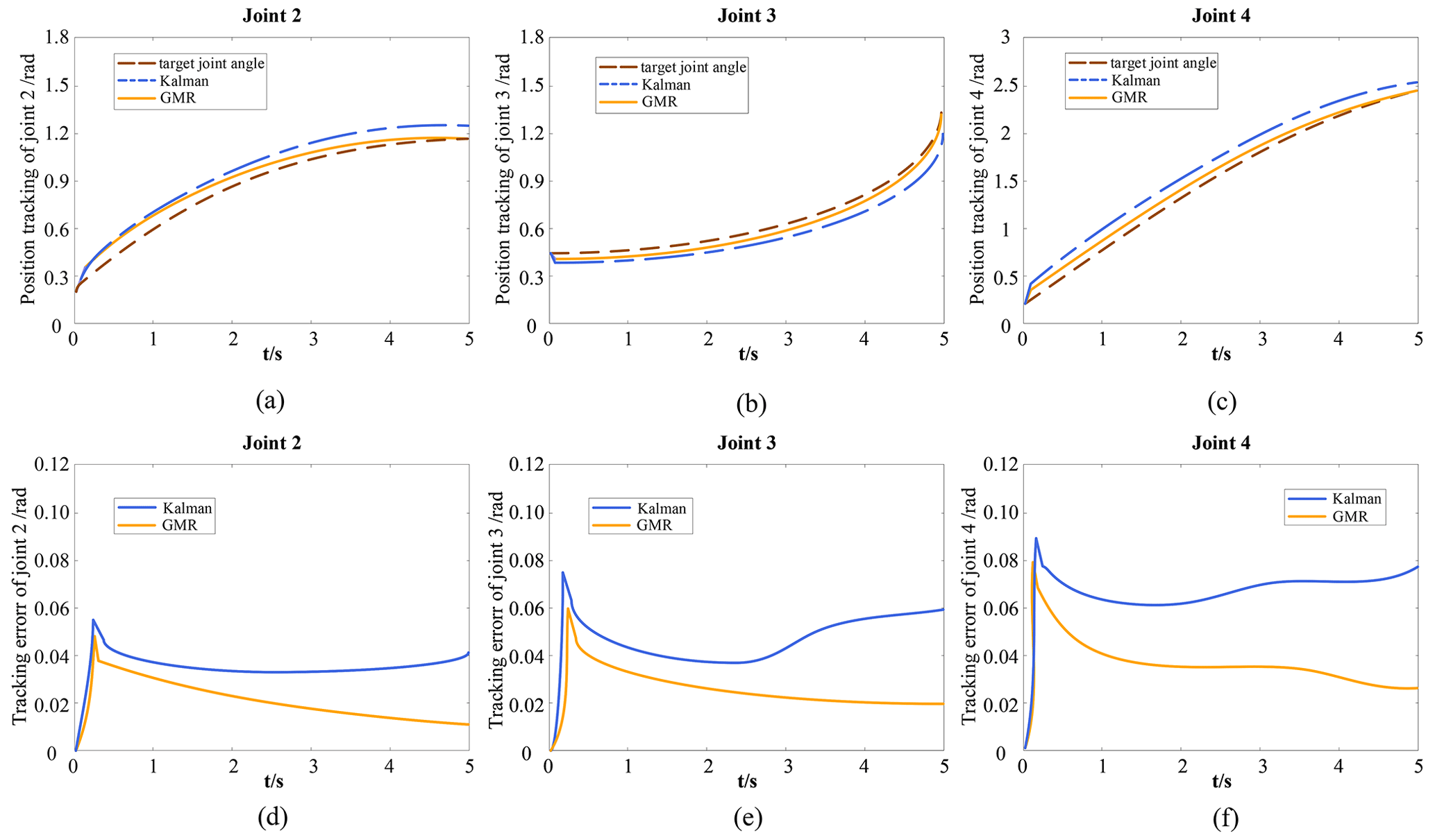
Figure 9Tracking and error curves of joint motion trajectories for GMR and Kalman methods. (a–c) Joint trajectory tracking curve. (d–f) Joint tracking error curve.
Figure 9a–c show the trajectory tracking curves of joints 2, 3, and 4. The dashed brown line represents the motion of the target joint angle, the solid orange line represents the motion of the joint angle of the GMR model, and the dashed blue line represents the motion of the joint angle of the Kalman model. Figure 9d–f show the tracking error curves of joints 2, 3, and 4. The solid orange line represents the tracking error in the GMR model, and the solid blue line represents the tracking error in the Kalman model. Figure 9d–f illustrate that the GMR model has a smaller trajectory tracking error than the Kalman model.
From the trajectory tracking curve and error tracking curve of joints 2, 3, and 4, it can be seen that the joints of the robot will have an error of 3–5∘ at the initial stage of motion. This is because when the robot enters the motion state from the static state, the moving joints will have a relatively large jitter, thus causing interference with the trajectory tracking. By comparing the error tracking curves of the Kalman model and the GMR model at each joint, the tracking error in the Kalman model increases significantly after 2 s. The reason for this is that the Kalman model has a relatively stable judgment for the prediction in a short time and cannot effectively process the long-term noisy trajectory data. The tracking error in the GMR model decreases with the increase in time, and its accuracy is higher than that of the Kalman model. In the tracking error curves of joints 2, 3, and 4, comparing the error changes in the GMR model and Kalman model within 0–1 s, it can be seen that the GMR model can reduce the tracking error in a shorter time. The reason for this is that the time variable is added to the GMR model and the continuity of robot movement with time is taken into account. Comparing the error tracking curve, it can be seen that the accuracy and reliability of the GMR model are better than the Kalman model, which proves that the OGG method has better real-time performance and learning ability.
5.4 Robot following experiment with the OGG method
In the working space, the robot can use 6 degrees of freedom to get to a particular point with a given attitude. The sewing task in this paper can be completed only with robot with 6 degrees of freedom (Schrimpf et al., 2014). In this paper, the TA6_R3_RevB1 robot in the laboratory is used to conduct physical verification experiments on the designed robot sewing action following the system. The robot has 6 degrees of freedom, and the DSP28335 is used as the controller of the robot. The controller and the robot are connected through controller area network (CAN) communication.
We perform a human sewing action follow-up verification experiment on a robotic platform with 6 degrees of freedom, as shown in Fig. 10a–f. The improved OpenPose model is used to obtain the coordinates of the upper-limb joint nodes of the human body in the sewing action. The joint coordinates are mapped to the robot system under ROS through the three-dimensional coordinate mapping. The GMM–GMR method is used to give the robot joint trajectory point speed and time attributes corresponding to the sewing action. The robot movement learns from a series of angle values corresponding to each joint and sends them to the controller. Each joint moves to the desired angle in turn to complete the tracking of the teaching sewing action.
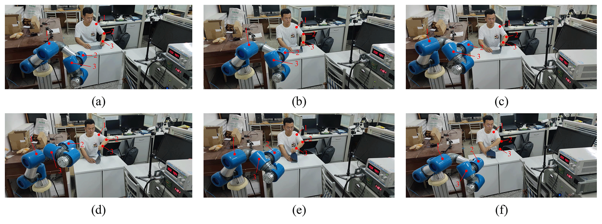
In the action of flipping the fabric, the end of the robot has a large range of motion in the workspace, which can test the accuracy of the OGG method more comprehensively. Therefore, taking the teaching sewing action of flipping the fabric as an example, the following experiment is carried out to compare trajectory tracking curves and corresponding error curves of joints.
To realize the mapping of joint pixel coordinates to robot three-dimensional coordinates, the position data in the robot workspace are obtained through the transformation matrix calculation. The sewing trajectory composed of the position data is the target trajectory, which obtains the target joint angle. The comparison method in Fig. 11 is the visual servo method in Fig. 1. The comparison results are shown in Fig. 11.
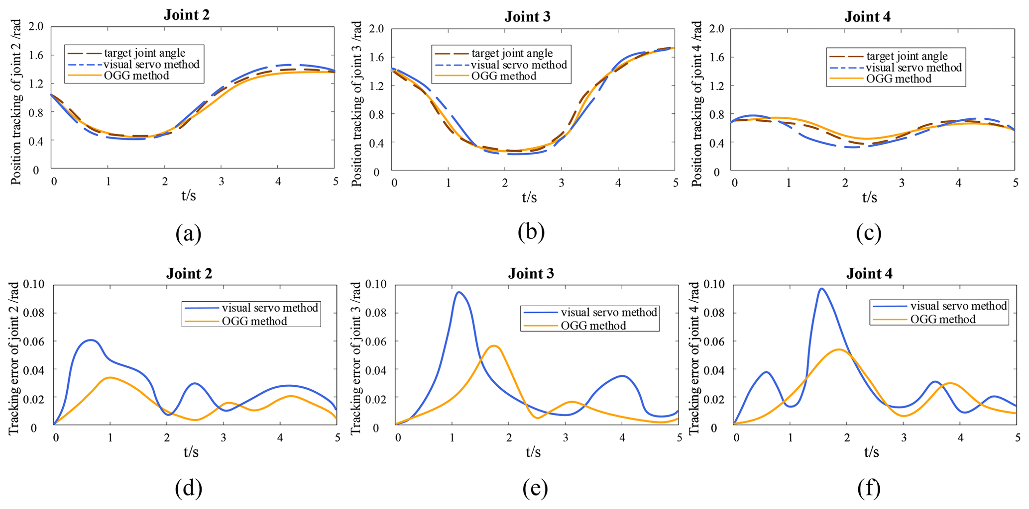
Figure 11Tracking and error curves of joint motion trajectories for OGG and visual servo methods. (a–c) Joint trajectory tracking curve. (d–f) Joint tracking error curve.
Figure 11a–c show the trajectory tracking curves of joints 2, 3, and 4. The dashed brown line represents the target joint motion, the solid orange line represents the joint motion after using the OGG method, and the dashed blue line represents the joint motion after using the visual servo method. Figure 11d–f show the tracking error curves of joints 2, 3, and 4. The solid orange line represents the tracking error in the OGG method, and the solid blue line represents the tracking error in the visual servo method. Figure 11 shows that the trajectory tracking error in the OGG method is smaller than that of the visual servo method.
It is observed that the results shown in Fig. 11 are similar to what was shown in Fig. 9, where there is an initial 3–6∘ error in the joint motion of the robot. By comparing the error tracking curves of the two methods, we found that the tracking error in the visual servo method increased significantly after 1 s, while the tracking error in the OGG method decreased over time and had a higher accuracy than the visual servo method.
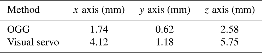
Furthermore, in an effort to compare which is better in terms of tracking between the OGG method and the visual servo method, we examined the two methods by comparing the precision of the robot end effector tracking the human wrist, during the action of flipping the fabric. In order to quantitatively analyze the accuracy of the robot end effector tracking the human wrist, we used the mean squared error (MSE) to evaluate its error. To avoid randomness, we collected 200 sampling points.
We analyzed the errors in the x-, y-, and z-axis directions of the robot workspace separately. The comparison results of the tracking errors in the two methods are shown in Table 3. The comparison of the data shows that the tracking accuracy of the OGG method is significantly better than that of the visual servo method.
We propose a vision-based robot sewing-action-following system. Through the robot sewing-action-following experiment in the simulation and the real environment, the following conclusions are drawn.
The improved OpenPose model can accurately obtain the sewing trajectory of the upper limb in a complex environment where the joints are occluded, ensuring the accuracy of action recognition. When the GMM mixes coding time factors and clustering nodes, the EM algorithm is used to process the clustering process of the sewing trajectory. The weight of the GMM is adjusted through the error analysis and weighted fusion of the ARIMA model, which increases the stability of the convergence process of the GMM. The experimental results show that the detection accuracy of the improved OpenPose model is 78.7 %, and the processing speed is 9.1 FPS. Compared with the visual servo method, the OGG method has a smaller overall error in the tracking accuracy of the robot's sewing movement. It is easier to achieve stability in the initial motion stage.
The experimental results show that the OGG method has a strong sewing-action-following ability. It can accurately detect workers’ sewing actions in complex scenes, which provides a theoretical basis and technical support for the intelligent development of collaborative sewing robots.
In human–robot collaborative sewing, worker and robot cooperate to complete complex sewing tasks. This paper only completed the robot imitation stage. To complete the collaborative sewing task, the robot also needs to go through a practice phase, gathering learning experience directly from online interaction. In the process of online interaction, the robot can update network parameters through model-free reinforcement learning. Meanwhile we also need to consider the safety of human–robot collaboration.
The data are available upon request from the corresponding author.
XW and PL planned the campaign. LZ and HW wrote code and performed the simulations. PL and XW analyzed the data. XW and LZ wrote the manuscript draft.
The contact author has declared that none of the authors has any competing interests.
Publisher’s note: Copernicus Publications remains neutral with regard to jurisdictional claims in published maps and institutional affiliations.
The authors acknowledge the financial support of the Natural Science Foundation of China, the Key Research and Development Plan of Shaanxi Province, China, the Graduate Scientific Innovation Fund for Xi'an Polytechnic University, and the Key Research and Development Program of Shaanxi Province.
This work has been supported by the Natural Science Foundation of China (grant no. 51905405), the Key Research and Development Plan of Shaanxi Province, China (grant no. 2019ZDLGY01-08), the Graduate Scientific Innovation Fund for Xi'an Polytechnic University (grant no. chx2023009), and the Key Research and Development Program of Shaanxi Province (grant no. 2022GY-276).
This paper was edited by Zi Bin and reviewed by three anonymous referees.
Ajoudani, A., Zanchettin, A. M., Ivaldi, S., Albu-Schäffer, A., Kosuge, K., and Khatib, O.: Progress and prospects of the human–robot collaboration, Auton. Robot., 42, 957–975, 2018. a
Baraglia, J., Cakmak, M., Nagai, Y., Rao, R. P., and Asada, M.: Efficient human-robot collaboration: when should a robot take initiative?, Int. J. Robot. Res., 36, 563–579, 2017. a
Billard, A. G., Calinon, S., and Dillmann, R.: Learning from humans, Springer handbook of robotics, 1995–2014, https://doi.org/10.1007/978-3-319-32552-1_74, 2016. a
Cheng, Q., Zhang, W., Liu, H., Zhang, Y., and Hao, L.: Research on the Path Planning Algorithm of a Manipulator Based on GMM/GMR-MPRM, Applied Sciences, 11, 7599, https://doi.org/10.3390/app11167599, 2021. a
Fan, Z., You, Y., Cai, X., Zheng, H., Zhu, G., Li, W., Garg, A., Deb, K., and Goodman, E.: Analysis and multi-objective optimization of a kind of teaching manipulator, Swarm Evol. Comput., 50, 100554, https://doi.org/10.1016/j.swevo.2019.06.011, 2019. a
Gu, S., Lillicrap, T., Sutskever, I., and Levine, S.: Continuous deep Q-learning with model-based acceleration, in: International Conference on Machine Learning, New York, New York, USA, 20–22 June 2016, PMLR, 48, 2829–2838, 2016. a
He, W., Li, Z., and Chen, C. P.: A survey of human-centered intelligent robots: issues and challenges, IEEE/CAA Journal of Automatica Sinica, 4, 602–609, 2017. a
Ijspeert, A. J., Nakanishi, J., Hoffmann, H., Pastor, P., and Schaal, S.: Dynamical movement primitives: learning attractor models for motor behaviors, Neural Comput., 25, 328–373, 2013. a
Kato, N., Li, T., Nishino, K., and Uchida, Y.: Improving multi-person pose estimation using label correction, arXiv [preprint], https://doi.org/10.48550/arXiv.1811.03331, 8 November 2018. a
Khansari-Zadeh, S. M. and Billard, A.: Learning stable nonlinear dynamical systems with gaussian mixture models, IEEE T. Robot., 27, 943–957, 2011. a
Kim, P. K., Park, H., Bae, J.-H., Park, J.-H., Lee, D.-H., Park, J., Kyung, J.-H., and Baeg, M.-H.: Intuitive programming of dual-arm robot tasks using kinesthetic teaching method, Journal of Institute of Control, Robotics and Systems, 22, 656–664, 2016. a
Kronander, K. and Billard, A.: Learning compliant manipulation through kinesthetic and tactile human-robot interaction, IEEE T. Haptics, 7, 367–380, 2013. a
Lang, X., Feng, Z., Yang, X., and Xu, T.: HMMCF: A human-computer collaboration algorithm based on multimodal intention of reverse active fusion, Int. J. Hum.-Comput. St., 169, 102916, https://doi.org/10.1016/j.ijhcs.2022.102916, 2022. a
Ma, L., Meng, Z., Teng, Z., and Qiu, W.: A reliability evaluation framework for smart meters based on AGG-ARIMA and PFR, Meas. Sci. Technol., 33, 045006, https://doi.org/10.1088/1361-6501/ac42e6, 2022. a
Ravichandar, H. C. and Dani, A.: Learning position and orientation dynamics from demonstrations via contraction analysis, Auton. Robot., 43, 897–912, 2019. a
Schenck, C., Tompson, J., Levine, S., and Fox, D.: Learning robotic manipulation of granular media, in: 1st Annual Conference on Robot Learning, Mountain View, California, USA, 13–15 November 2017, PMLR, 78, 239–248, 2017. a
Schrimpf, J., Bjerkeng, M., and Mathisen, G.: Velocity coordination and corner matching in a multi-robot sewing cell, in: 2014 IEEE/RSJ International Conference on Intelligent Robots and Systems, Chicago, IL, USA, 14–18 September 2014, IEEE, 4476–4481, https://doi.org/10.1109/IROS.2014.6943196. 2014. a
Wrede, S., Emmerich, C., Grünberg, R., Nordmann, A., Swadzba, A., and Steil, J.: A user study on kinesthetic teaching of redundant robots in task and configuration space, Journal of Human-Robot Interaction, 2, 56–81, 2013. a
Xie, J., Gong, J., Wu, S., Xiong, G., and Lu, C.: A personalized curve driving model for intelligent vehicle, in: 2017 IEEE international conference on unmanned systems (ICUS), Beijing, China, 7–29 October 2017, IEEE, 301–306, https://doi.org/10.1109/ICUS.2017.8278359, 2017. a
Yanagihara, Y., Muto, S., and Kakizaki, T.: Evaluating user interface of multimodal teaching advisor implemented on a wearable personal computer, J. Intell. Robot. Syst., 31, 423–438, 2001. a
Ye, K., Dong, J., and Zhang, L.: Digital Analysis of Movements on Characters Based on OpenPose and Dlib from Video, J. Phys. Conf. Ser., 2218, 012021, https://doi.org/10.1088/1742-6596/2218/1/012021, 2022. a
Yunus, A. P., Shirai, N. C., Morita, K., and Wakabayashi, T.: Comparison of RNN-LSTM and Kalman Filter Based Time Series Human Motion Prediction, J. Phys. Conf. Ser., 2319, 012034, https://doi.org/10.1088/1742-6596/2319/1/012034, 2022. a
Žlajpah, L.: Simulation in robotics, Math. Comput. Simulat., 79, 879–897, 2008. a
- Abstract
- Introduction
- Overview of the OGG method framework
- Sewing action recognition method
- Robot sewing-action-following method
- Experiment and result analysis
- Conclusions
- Data availability
- Author contributions
- Competing interests
- Disclaimer
- Acknowledgements
- Financial support
- Review statement
- References