the Creative Commons Attribution 4.0 License.
the Creative Commons Attribution 4.0 License.
 | 11 Jul 2023
An investigation into the micro-geometric tapered-shape surface design of the piston bore of a piston–cylinder interface in an axial piston motor
Yishan Zeng
Min Hu
Huabing Zhu
Changhai Liu
Lei Wang
In pursuit of design solutions that reduce energy loss and improve wear resistance for the piston–cylinder interface in an axial piston motor, a fluid-structure interaction numerical model and a new test rig of the friction force of the piston–cylinder pair are developed to achieve the analysis and design of the micro-geometric tapered-shape surface of a piston bore. The piston bore with the tapered-shape surface axial distribution length ratio of 49.44 % of the overall length is found to be the relatively optimized one. Furthermore, how the shaft speed, load pressure, and swash plate angle influence the performance of the two-type interface is analyzed. Numerical analysis results show that, compared with the traditional cylindrical piston bore design, the piston–cylinder interface with the optimized tapered-shape piston bore in the axial piston motor can achieve a significant reduction in leakage flow and friction force, and the experimental results are consistent with the simulation results.
- Article
(13744 KB) - Full-text XML
- BibTeX
- EndNote


As an essential actuator in hydraulics, an axial piston motor whose energy losses and wear phenomena get more obvious with the increase in load pressure and shaft speed is widely used in industry and mobile machines (Li et al., 2019). The piston–cylinder pair represents one of the most critical design elements of the axial piston motor to realize its function (Shang and Ivantysynova, 2018; Ye et al., 2019). Differently from other friction pairs in axial piston machines, the piston–cylinder pair cannot be designed based on the principle of static and dynamic pressure balance due to its inherent structural principle. Being a pure hydrodynamic bearing, the piston–cylinder interface fulfills simultaneously bearing and sealing functions under oscillating load conditions, which causes the piston–cylinder pair to be subjected to a huge lateral force and bending moment (Shang and Ivantysynova, 2019). For these reasons, a large number of studies aimed at improving the wear resistance and antifriction performance of the piston–cylinder pair have been carried out so far, such as the surface shaping and texturing and the material coating on the surface, which form the basis for the energy-saving and longer-service life designs of the piston–cylinder pair.
Surface texturing is usually achieved by using the laser surface texturing technique, which creates microscale surface patterns with a certain distribution and size on the friction-pair surface to improve the tribological properties of the contact surface (Chen et al., 2019). Ivantysynova and Lasaar (2004) found that machining the piston surface with microscale sinusoidal patterns can significantly reduce power losses of the piston pair under all operating conditions. Jia et al. (2021) studied the effects of different radii, depths, and densities of micro-dimples on the performance of the piston–cylinder pair and found that the friction force can be reduced by 27.8 % under optimal parameters. Step multiple-groove design and combine design were proposed by Ma et al. (2019) to maximize lubrication and minimize the friction of the piston–cylinder pair by studying the effects of grooves and dimples on the friction performance. Yin et al. (2021) discovered that laser-textured surfaces can enhance the friction performance of low-viscosity media by the research friction-and-wear performance of a typical surface texture on the plunger under diesel and methanol lubrication. In addition, micro-texturing can trap debris and prevent severe abrasive wear. Due to its high degree of freedom, surface texturing can be tailored to different operating conditions and applications of axial piston machines (Zhang et al., 2018). However, not all textures are effective, and not all promising textures work positively in all lubrication regimes. Moreover, ensuring the durability of micro-textured surfaces is a challenging task. Surface coating is a process where a thin film of one or more different materials is applied to the surface of the piston–cylinder pair to strengthen the surface and improve the load-carrying capacity of the piston–cylinder pair. Murrenhoff and Scharf (2006) and Murrenhoff (2011) studied the application of the physical vapor deposition (PVD) method using graded zirconium carbide coating on the piston, and the experimental results showed that coated pistons of an axial piston machine reveal limited wear within the first hours of operation and very low friction between piston and bushing. Zhang et al. (2019) evaluate the wear of two different materials (ceramic and 30Cr2MoVA) of friction pairs of an ultra-high-pressure axial piston by means of experimental investigations and found that ceramic materials perform better in an ultra-high-pressure pump. Similar to surface texturing, surface coating requires a separate machining step, and as an additive process, the influence of the thicknesses of different coating materials needs to be considered in the design stage. These limitations restrict the large-scale application of these techniques in axial piston machines.
For the design of the piston–cylinder pair, surface shaping is considered one of the most important and promising technologies for improving the wear resistance and antifriction performance due to its effectiveness and the ability to implement it directly during the component-processing stage. Yamaguchi and Tanioka (1976) for the first time proposed a tapered piston shape to utilize an improved hydrodynamic pressure built up with axial piston motion. Ivantysynova (1983) proposed a barrel-like piston with a large curvature radius leading to a diameter reduction of 4 mm at both piston ends. The idea of optimizing the piston shape to minimize energy dissipation within the piston–cylinder interface was continued by Ivantysynova and Lasaar (2004), who proposed a half-barrel-like piston. A new version of a fully coupled fluid–structure interaction model of the piston–cylinder interface was developed by Pelosi and Ivantysynova (2011), which was used to conduct a simulation study for waved pistons. Based on this newly developed fluid–structure interaction model, the simulation study for the barrel piston, the new flat piston, and the waved barrel piston proposed by Wondergem and Ivantysynova (2014) was conducted. The shaped piston showed lower friction than and comparable leakage to the cylindrical piston. Murrenhoff and Scharf (2006) presented several research works on shaping of the piston and bushing together with piston and bushing coatings as well as the first investigations into surface texturing. A design study was conducted by Ernst and Ivantysynova (2017, 2018) to investigate the effects of a surface shape that can be applied to the cylinder bores of axial piston machines with the goal of improving load support while keeping down leakage in the critical piston–cylinder tribological interface of axial piston machines operating at high pressures with water as their hydraulic fluid. For the purpose of mitigating the solid friction and wear resulting from the use of water as a hydraulic medium, due to its low viscosity, Ernst et al. (2020, 2022) developed the Tailored Profile Generator Algorithm (TPGA) to create effective bore shapes by adapting the surface to conform with that of the corresponding piston in a manner conducive to hydrodynamic pressure buildup. A pressurized groove around the bushing inside the cylinder block was proposed by Sarode and Shang (2019) to improve the net energy dissipation from the piston–cylinder interface by 15 %–25 %. Lyu et al. (2020) and Zhang et al. (2021) conducted a study on the wear prediction of the piston–cylinder pair in axial piston pumps, and a machinable surface contour of the cylinder bore was designed based on the wear contour at the lowest wear rate. The experimental results show that the pre-machined contour reduces the wear rate during the initial operating stage.
All of these studies over the past decades have demonstrated huge potential to achieve a major reduction in energy dissipation and improvement in load-carrying capacity for the piston–cylinder interface by altering the geometry along with the configuration of the piston–cylinder interface. Most related studies have chosen axial piston motors as their research object due to the structural similarities of axial piston machines. As a result of the differences in the working principle between axial piston motors and axial piston pumps, however, research has found that the axial piston motor's oil distribution mechanism is different from the piston pump, and there are serious internal leakage losses between the high- and low-pressure oil cavities of the piston motor (Xu et al., 2017). It is necessary to analyze and design the structure of the piston–cylinder interface suitable for piston motors to meet the demands of energy saving, high working efficiency, and a long service life of hydraulic components brought about by industrial development. This paper aims to investigate a micro-geometric tapered-shape design of the piston bore for a piston–cylinder pair within axial piston motors. The tapered-shape piston bore is characterized in that the diameter of the piston bore is continuously and gradually reduced along the direction toward the housing, and the shape is simple and easy to manufacture. The performance of the piston–cylinder pair with the tapered-shape piston bore was studied utilizing a developed fluid–structure interaction numerical simulation model and a newly designed test rig of the friction force of the piston–cylinder pair.
2.1 Analysis of the external load acting on the piston–slipper assembly
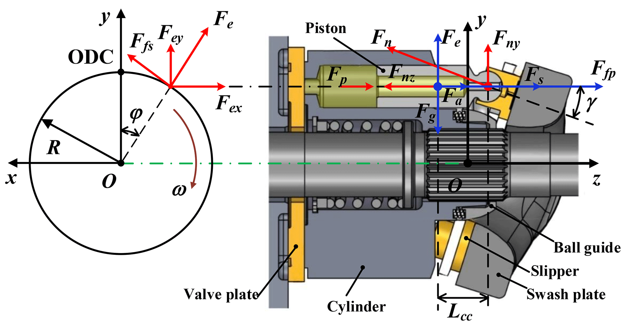
A schematic view of the external load acting on the piston–slipper assembly at an angular position of φ relative to the outer dead center (ODC) is shown in Fig. 1. The total load forces Flx and Fly of the piston–slipper assembly in the x direction and the y direction, respectively, are as follows:
With respect to the piston head ball center, the external moments Mlx and Mly, respectively, acting on the piston–slipper assembly can be deduced as follows:
where Fn represents the reaction force exerted on the slipper by the swash plate, Ffs denotes the friction force of the slipper–swash plate pair, Fe represents the centrifugal force of the piston–slipper assembly, which acts at the center of mass and always points outwards in the radial direction, and Lcc denotes the distance between the center of mass of the piston–slipper assembly and the ball center of the piston head.
2.2 Numerical calculation of the microscopic characteristics of the oil film within the piston–cylinder pair
2.2.1 Oil film morphology
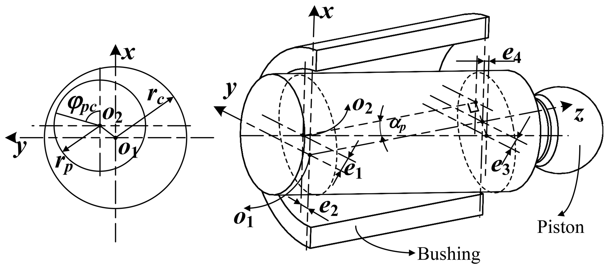
A coordinate system o1xyz with the z axis along the center line of the piston chamber is established as shown in Fig. 2. The piston generally exhibits an inclined posture in the piston bore, with the tilt angle denoted by αp. The eccentricity is the distance between the center points of the piston bore and the piston, and it can be determined by taking two cross sections of the piston cut from the two end-faces of the bushing. The eccentricities are denoted as (e1, e2), which is near the end of the piston bottom, and (e3, e4), which is near the piston ball (Zhang et al., 2020).
With the eccentricities (e1, e2) and (e3, e4), the local oil film depth hp at each point of the fluid domain of the piston–cylinder interface can be derived:
where lf represents the initial gap length between piston and bushing, and lz represents the position of the oil film along the axial direction of the piston chamber, i.e., the z-axis direction depicted in Fig. 2. φpc denotes the angular position of the oil film in the circumferential direction around the piston. Δhp denotes the contribution to the oil film depth due to the surface deformation of the solid boundary at the friction interface of the piston–cylinder pair. rc and rp, respectively, represent the inner radius of the piston bore and the outer radius of the piston.
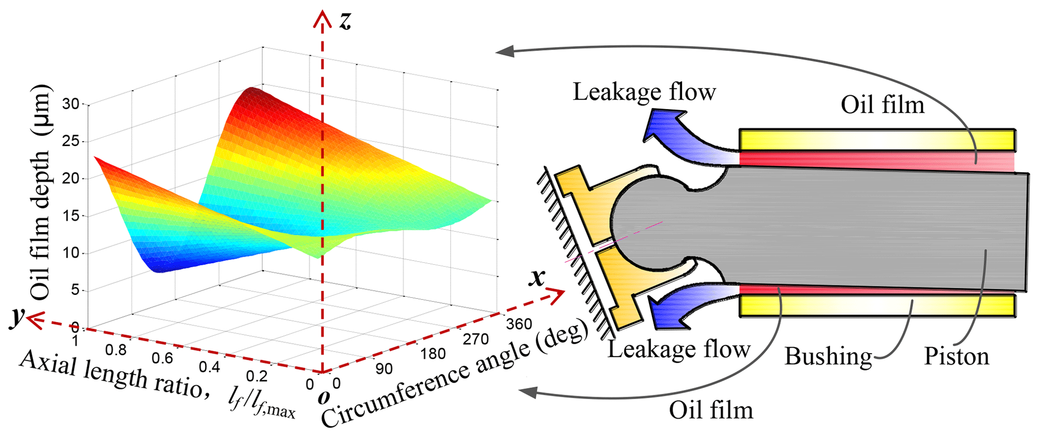
The curvature radius of the interface in contact with the oil film is typically in the centimeter range, much larger than the clearance between the piston and the cylinder, which is only about a few tens of micrometers. The film shape of the piston–cylinder pair can be unwrapped and viewed as a periodic profile with the angular position φpc compared with rc and rp (Ivantysynova and Lasaar, 2004). Figure 3 shows a typical view of the piston–cylinder pair oil film depth on the unwrapped Cartesian coordinate system o–xyz. In particular, the oil film depth in an unwrapped Cartesian coordinate system presents the following coordinates:
In order to balance the time-changing external load exerted on the piston–slipper assembly, the piston needs to continuously self-adjust its eccentricity to generate sufficient hydrodynamic pressure buildup in the oil film for the purpose of generating an appropriate load-carrying ability for the oil film of the piston–cylinder pair. The change rate of the inclined position of the piston can be defined by the piston eccentricities' temporal derivative vector , , , . The balanced condition can be expressed as
where , , and Fl(t) represent the total external loads acting on the piston–slipper assembly, and represents the total support force generated in the oil film of the piston–cylinder pair. When a balanced condition is achieved, the proper squeeze motion of the piston is determined; i.e., the vectors e and are determined. According to Eq. (5), the corresponding oil film depth and film shape can be calculated and obtained.
2.2.2 Reynolds equation
As shown in Fig. 3, the lubricating interface is defined in the (x, y) plane, and z is the direction of the film depth typically on the order of a few microns. The Reynolds equation is derived from the Navier–Stokes (N–S) and continuity equations. The N–S equation allows the fluid velocity in the lubricating interface of the piston–cylinder pair to be expressed. The N–S equation, expressed for a Newton fluid, states that
The mathematical model expression of the oil film pressure of the piston pairs can be derived as Eq. (9) (Zhang et al., 2020):
where μ is the viscosity of the oil film of the piston–cylinder pair, p is the pressure of the oil film of the piston–cylinder pair, and ωp is the angular speed of the piston revolving on its axis.
The first two terms on the right-hand side of Eq. (9) indicate the hydrodynamic effect of the wedge-shaped oil film of the piston–cylinder pair, and the third term represents the oil film squeezing effect caused by the microscopic radial movement of the piston. The pressure buildup in the oil film of the piston–cylinder pair is the result of the interaction of the two effects. The Reynolds equation is a partial differential equation with a diffusion term and a source term and cannot be analytically solved. Compared with other methods such as the finite-difference method and the boundary-element method, the finite-volume method (FVM) is often used to solve complex fluid problems such as an oil film due to its high accuracy, good numerical stability, and high computational efficiency. Therefore, the FVM is used for numerical calculation in this study (Xu et al., 2012).
The hydrodynamic effect and the squeezing effect occurring in the oil film may cause the local extremely high pressure peak, which can significantly affect the viscosity of a fluid film. The pressure–viscosity effect is defined as
where ζ represents the viscosity–pressure coefficient and μ0 represents the viscosity of oil at 40 ∘C and 1 atm.
2.2.3 Fluid–structure interaction and the solution of the surface elastic deformation
The high operating pressures and even higher pressure peaks generated in the fluid film between the piston and cylinder-lubricating interface exert significant loads on the piston and cylinder boundary surfaces. The pressure load on the solid surfaces causes an elastic deformation of the structure, which may reach the same order of magnitude as the film depth itself. The surface elastic deformation of the piston and cylinder and its interaction with the fluid film leads to an elastohydrodynamic lubrication regime.
Both the piston and the bushing surfaces undergo structural deformation under the pressure field of the oil film. However, due to the piston being made of steel and the bushing being made of brass alloy, a soft material compared with steel, the amount of structural deformation generated on the bushing surface is much greater than that generated on the piston surface. Therefore, the amount of structural deformation on the piston surface can be neglected, and only the deformation of the bushing should be considered. Based on the superimposition principle, the surface elastic deformation can be calculated by the deformation matrices method described by the following equation:
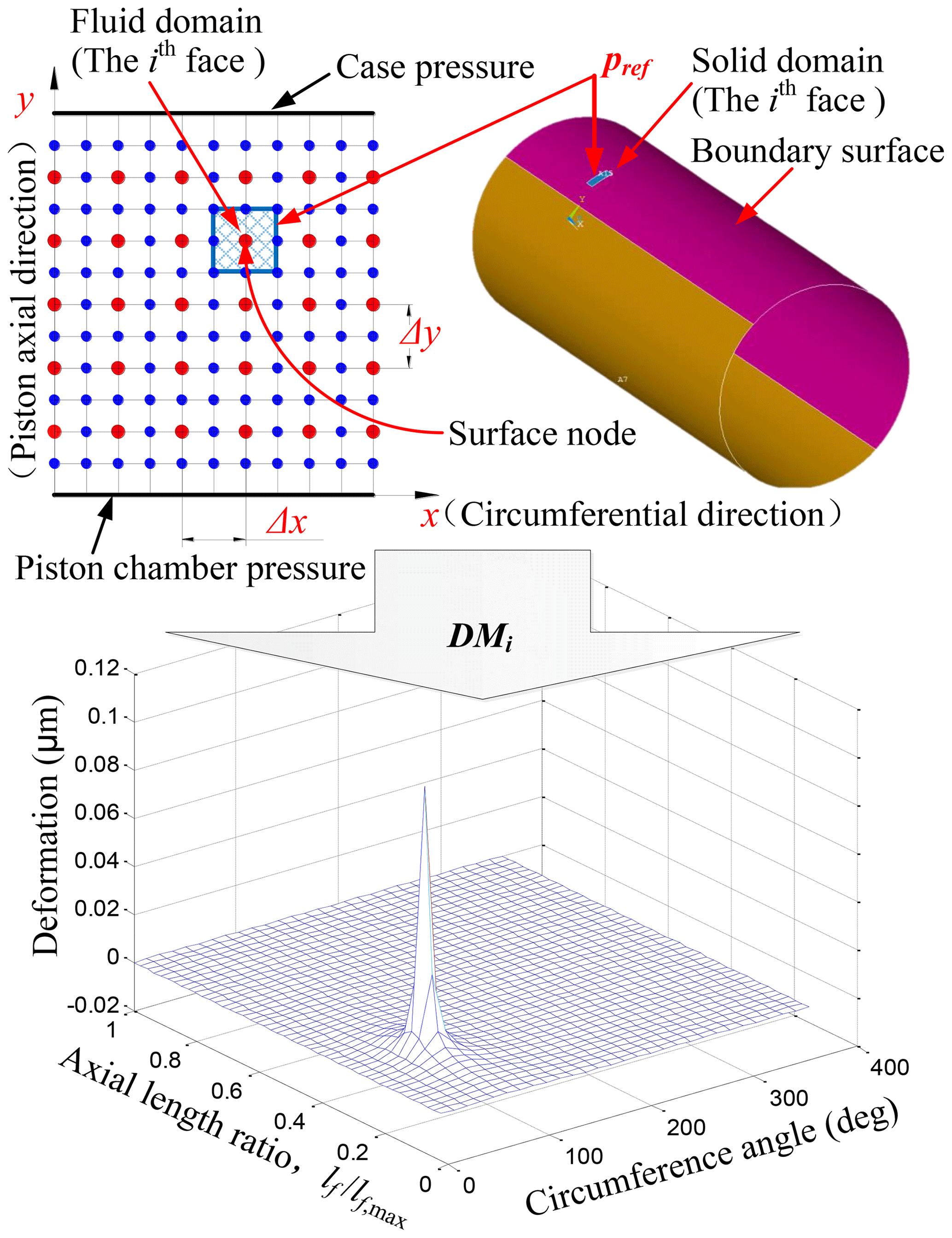
where Δhp is the array containing the elastic deformation of each of the surface nodes of the piston–cylinder solid domain, pref is the reference pressure acting on each face of the solid surface defining the fluid film boundary, pi is the external actual fluid pressure acting on each of the N faces of the boundary surface, and DMi represents the ith face deformation matrix, containing the elastic deformation of all the surface nodes, when the ith face is loaded with a reference pressure pref. Figure 4 shows the deformation matrix DMi, i.e., the deformation field corresponding to the ith face element loaded with a reference pressure of 10 MPa. Δx and Δy, respectively, represent the angle interval and length interval of fluid film pressure field nodes. After superimposing and summing the deformation matrices DMi, the deformation distribution can be obtained as shown in Fig. 5.
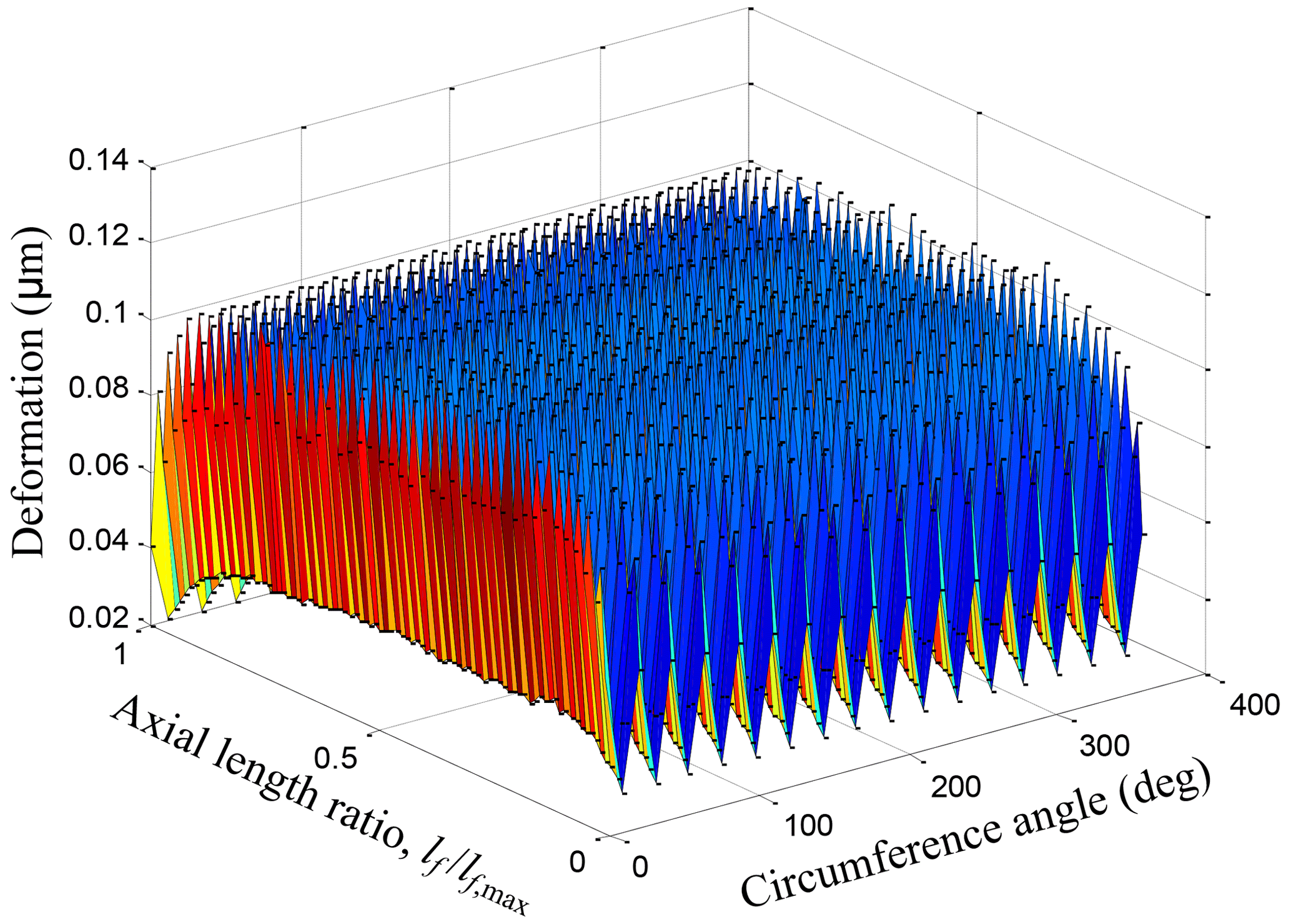
With Eq. (15), the deformation due to pressure loading can be recalculated directly and quickly at each of the Reynolds equation iterative steps using the integrated finite-element method (FEM) code. The deformations are ultimately locally added to the fluid film depth according to the previous Eq. (5), directly affecting the lubricating film dynamic pressure field buildup. In order to determine the deformation to modify the lubricating film depth field according to Eq. (15), a set of deformation matrices is calculated offline for the piston and cylinder boundary surface at the beginning of the simulation, relying on the external mesh generation and FEM analysis for the mechanical bodies of the piston and the cylinder from computer-aided diagnosis (CAD) based on the hexahedron or tetrahedron elements.
2.3 Modeling of the tapered-shape piston bore
Figure 6 shows schematically the comparison of the surface profile shape of the traditional standard cylindrical-shape piston bore and the tapered-shape piston bore proposed in this study. At the piston–cylinder interface of the piston–cylinder pair, bushings are quite often used within the cylinder bores for the purpose of separating the piston from the bulk material of the cylinder. Since the pistons are almost always made of steel, from a tribological standpoint, a bushed cylinder is always used when the bulk material of the cylinder is steel as well. In this case, the bushings are generally made of a high-strength brass. In addition, the cylinders of many axial piston machines are usually made of ductile iron. In this case, the bushings can be eliminated. The steel pistons can run successfully on the ductile iron surface due to the differences in the mating materials and their associated hardness. The tapered-shape surface in Fig. 6 is designed on the surface of the bushing, and similarly, in the case of a ductile iron cylinder without bushing, the tapered shape is designed directly on the cylinder bore surface.
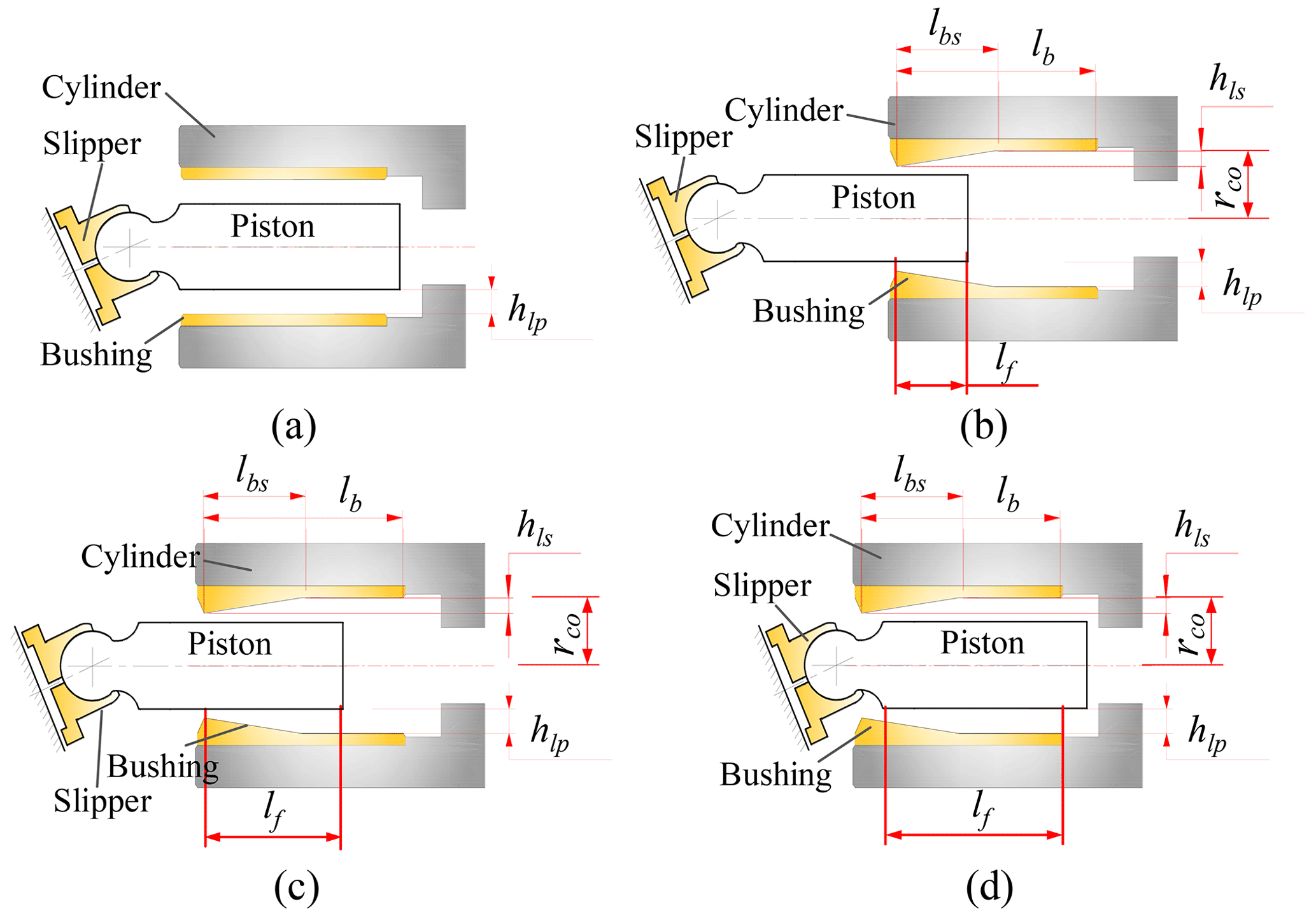
Figure 6Schematic diagram of surface shapes of the piston bores. (a) Traditional cylindrical shape. (b) Tapered shape (position 1). (c) Tapered shape (position 2). (d) Tapered shape (position 3).
The reciprocating motion of the piston within the piston bore is divided into three phases so as to describe and model the tapered-shape surface of the piston bore according to the different positions of the piston relative to the piston bore as depicted in Fig. 6b–d. Firstly, according to the representation of the oil film fluid domain meshing diagram shown in the previous Fig. 4, the axial length yj of the film depth field node (i, j) from the boundary of the piston–cylinder contact area on the piston chamber side can be expressed as
For position 1 depicted in Fig. 6b, position 2 depicted in Fig. 6c, and position 3 depicted in Fig. 6d, the inner radius rc of the corresponding piston bore at the film depth field node (i, j) should be corrected by the following:
where rco, lbs, lf, and hls, respectively, are defined schematically in Fig. 6. Substituting Eqs. (13)–(15), respectively, into Eq. (5) of the film depth calculation equation according to the corresponding piston position relative to the piston bore ultimately contributes to the oil film depth modifications due to the tapered-shape surface of the piston bore.
2.4 Calculation of the energy dissipation characteristic parameters of the piston–cylinder pair
The energy dissipation of the piston–cylinder pair is mainly composed of frictional losses and leakage losses (Fang and Shirakashi, 1995). As shown in Fig. 2, the piston is in a tilted position within the piston bore. There is a minimum value of oil film thickness of the piston–cylinder pair, hcd, due to the surface roughness. When the eccentricity of the piston within the piston bore is too large, the lubrication state of the piston–cylinder pair will transition from a fully lubricated state to a mixed-lubrication state in the region where the oil film thickness is less than hcd. In mixed lubrication, part of the load is supported by the oil film, while the other part is supported by surface asperities in contact. The frictional force generated by the rough peak contact of the asperities is much greater than the frictional force generated by fluid viscosity. Therefore, mixed-friction loss is the main form of frictional loss in the piston–cylinder pair. The mixed-friction force Ffpm can be expressed as follows:
where τfm represents the friction shear stress of the unit body at the friction interface, which is related to the material, the surface roughness, and the temperature distribution in the tribological pair. Am represents the mixed-friction area dependent on the root-mean-square deviation of the surface roughness, i.e., the root-mean-square deviation Rqp of the surface roughness of the piston surface and the root-mean-square deviation Rqc of the surface roughness of the piston bore surface, both of which are about 1.2–1.25 times the arithmetic average deviations of Rap and Rac. In this study, Rap and Rac are both equal to 0.2, which means that the mixed friction occurred in a partial area with the depth of the oil film less than 1 µm.
For a certain manufactured piston and cylinder, the τfm in Eq. (16) almost remain constant under the same operating conditions of temperature, pressure, and speed. Therefore, in this case the mixed-friction force Ffpm can be reflected by the mixed-friction area Am, which indicates that the mixed friction occurs and that its magnitude is proportional to frictional losses in the mixed-lubrication area of the piston–cylinder pair. In addition, the mixed-friction area can be determined by the critical oil film depth hcd calculated by the following Eq. (17). The film thickness ratio ζp in Eq. (17) is the ratio of the critical oil film depth to the comprehensive roughness of the contact surface. It is used to determine the three lubrication states of boundary lubrication, mixed lubrication, and fluid lubrication. Furthermore, the case of ζp≤3 generally can be considered the one when the mixed friction occurs, corresponding to the lower film depth rather than the critical film depth. If the number of film thickness field nodes lower than the critical film depth is assumed to be Nm, which could be counted by the calculated film depth, then the total mixed-friction area Am could be calculated by
From the fluid velocity distribution in the oil film, expressed by Eq. (10), the viscous shear stresses on piston and cylinder surfaces can be derived by considering the fluid to be Newtonian. In particular, z=0 is the cylinder surface and z=hp is the piston surface. The total viscous friction forces Ffpx and Ffpy acting on the different surfaces were derived by integrating the viscous shear stresses τpx and τpy, respectively, in the circumferential and axial directions over the piston and cylinder surface areas and as follows:
where vx and vy, respectively, represent the velocity of the local point of the oil film along the x-axis direction and the y-axis direction, and vωx represents the velocity determined by the angular speed ωp of the piston revolving on its axis and the radius of the piston rp, i.e., vωx=ωprp (Pelosi, 2012).
The volumetric loss of leakage flow can also be derived from the integration of the velocity distribution in the axial direction over the efflux area. Due to the continuity ensured by the Reynolds equation, this flow rate is constant over the entire oil film length for each chosen cross section. The expression for the instantaneous leakage flow Qpc is
2.5 The complete iterative solution scheme
The complete solution scheme can be described referring to Fig. 7, which consists of three loops in this overall solution scheme, i.e., the viscosity–pressure loop, the pressure–depth loop, and the computing cycle loop.
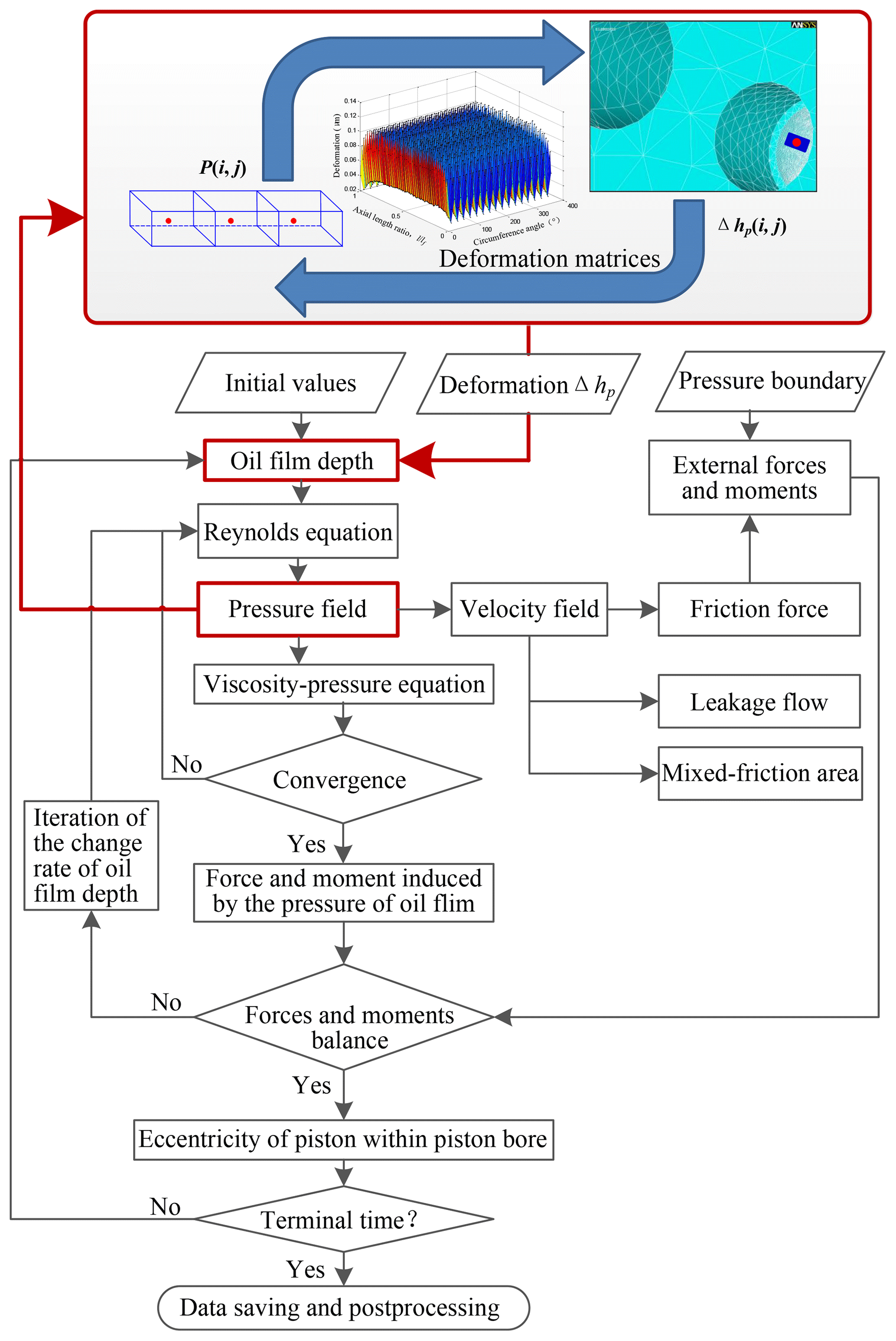
During the simulation, the fluid viscosity and the surface elastic deformation due to the dynamic pressure field are updated at each iteration step. The pressure–deformation convergence is obtained using an under-relaxation fixed-point Picard iteration scheme, which adjusts the under-relaxation coefficients proportionally to the pressure residual behavior. Several revolutions of the machine are simulated, solving in time at discrete intervals corresponding to a progressively increasing shaft rotation and different load conditions as well as the terminal time of the computation set by the user. A typical time step for the simulation corresponds to Δφ=0.5∘.
3.1 Optimization of the tapered-shape surface
The relative ratio of the mixed-friction area is the mixed-friction area that occurs in the piston–cylinder interface to the current overall area of the interface. The decrease in the relative ratio of the mixed-friction area of the piston–cylinder pair is considered the most important performance parameter for determining the optimized tapered-shape surface of the piston bore. Simulations for a sequence of progressively increasing axial distribution lengths of the tapered-shape surface of the piston bore were conducted first. The simulation results are given in Fig. 8 for a fixed height of hls=7 µm and at the different swash plate angles of 7 and 16∘, and the relative ratio of the mixed-friction area reaches almost the same minimum at the 49.44 % and 67.52 % axial distribution length ratios of the tapered-shape surface of the piston bore. From the standpoint of the manufacturability and maintaining the essential seal length of the cylindrical-shape surface of the piston bore, the tapered-shape surface axial distribution length ratio of 49.44 % is determined to be the optimized one.
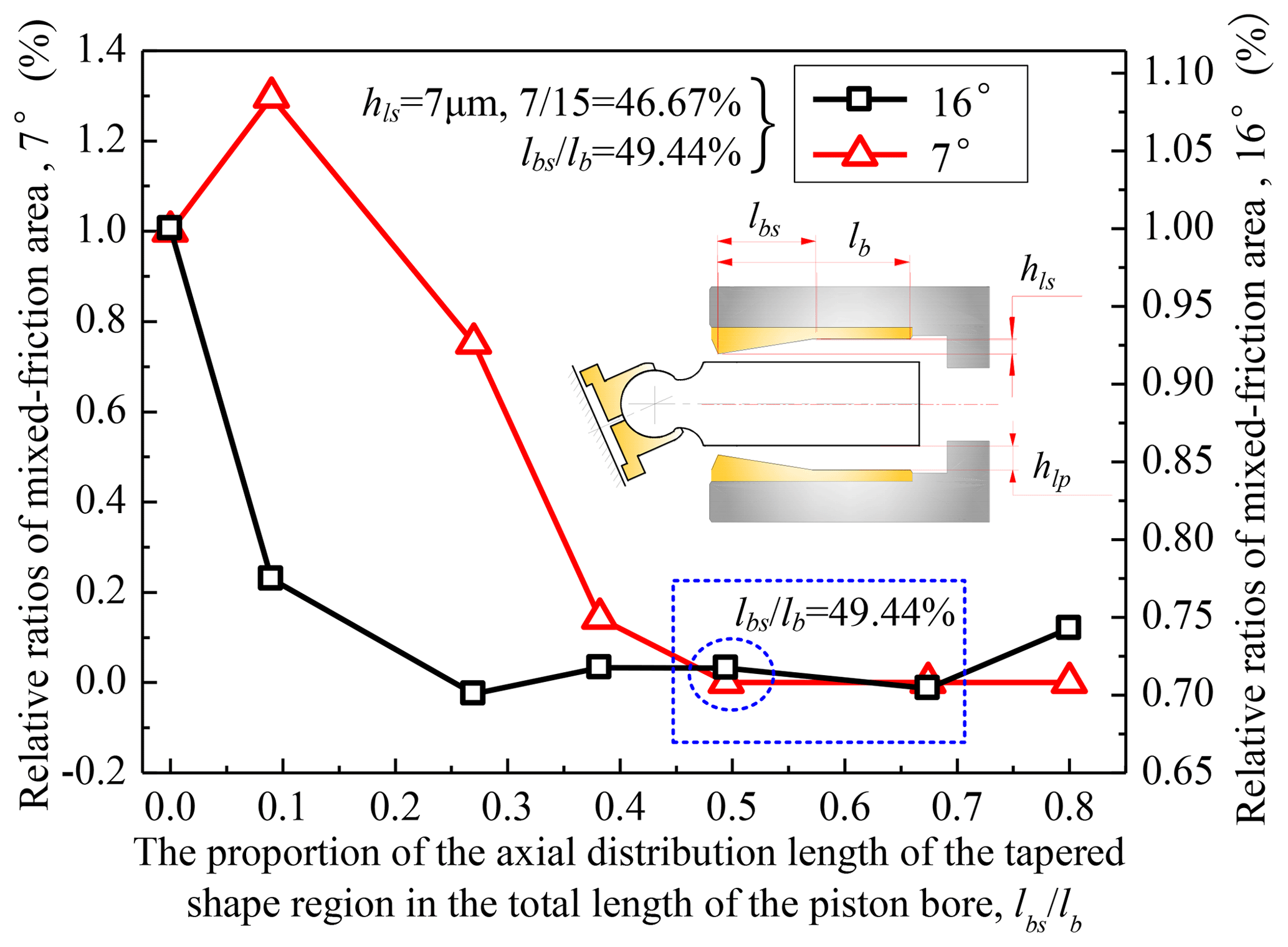
Figure 8Comparison of the relative ratios of the mixed-friction area for a sequence of a progressively increasing axial distribution length of the tapered-shape surface of the piston bore, at the swash plate angles of 16 and 7∘ and the height of hls=7 µm.
3.2 Numerical analysis of the performance of the optimized tapered-shape piston bore
The energy dissipation in the piston–cylinder pair is mainly composed of frictional losses and leakage losses. As mentioned earlier, mixed-friction force can be characterized by the mixed-friction area, which can not only reflect mixed-friction losses, but also the lubricating capacity of the oil film through magnitude. Its size is proportional to frictional losses in the mixed-lubrication area of the piston–cylinder pair (Manring, 1999). A series of numerical simulations was performed with respect to different operating parameters for analyzing the performance of the piston–cylinder pair with and without the optimized tapered-shape surface piston bore, and the performance of the piston–cylinder pair was characterized by the mixed-friction area and the leakage flow. Operating parameters include shaft working speed, load pressure, and swash plate angle, which reflects displacement.
In order to quantitatively summarize the results of the above comparative analysis, ζc and ζz are defined to represent the calculated value of the piston–cylinder pair with the tapered-shape piston bore and the piston–cylinder pair with the traditional cylindrical-shape piston bore, respectively. The relative change rate δcz is defined as in Eq. (21), which can be used to represent the energy dissipation. When the energy dissipation of the piston–cylinder pair with the tapered-shape piston bore is smaller than that with the traditional cylindrical-shape piston bore under the same working conditions, the relative change rate δcz is negative. Figures 9 and 10 show the comparison of the mixed-friction area simulation results and the comparison of the leakage flow simulation results, respectively, over one shaft revolution under the conditions of fixed displacement, fixed load pressure, and changing shaft speed. More comparison results corresponding to a wide range of operating conditions are shown in Fig. 11, which gives a concise view of the influence that the tapered-shape piston bore has on the mixed-friction area and the leakage flow of the piston–cylinder pair.
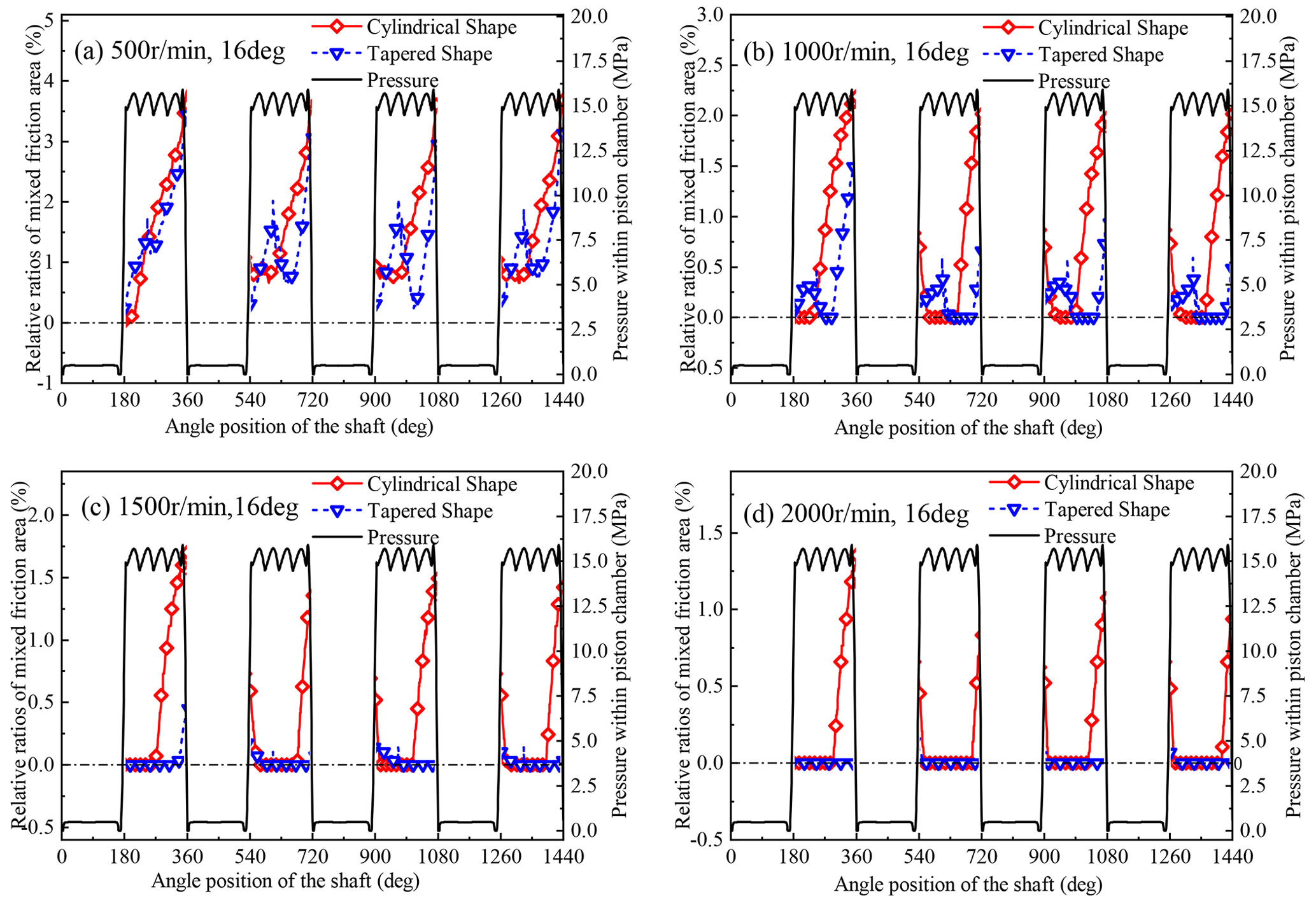
Figure 9Comparison of the mixed-friction area taking place at the piston–cylinder interface at the swash plate angle of 16∘, load pressure of 15 MPa, and a different working speed: (a) 500 rpm; (b) 1000 rpm; (c) 1500 rpm; (d) 2000 rpm.
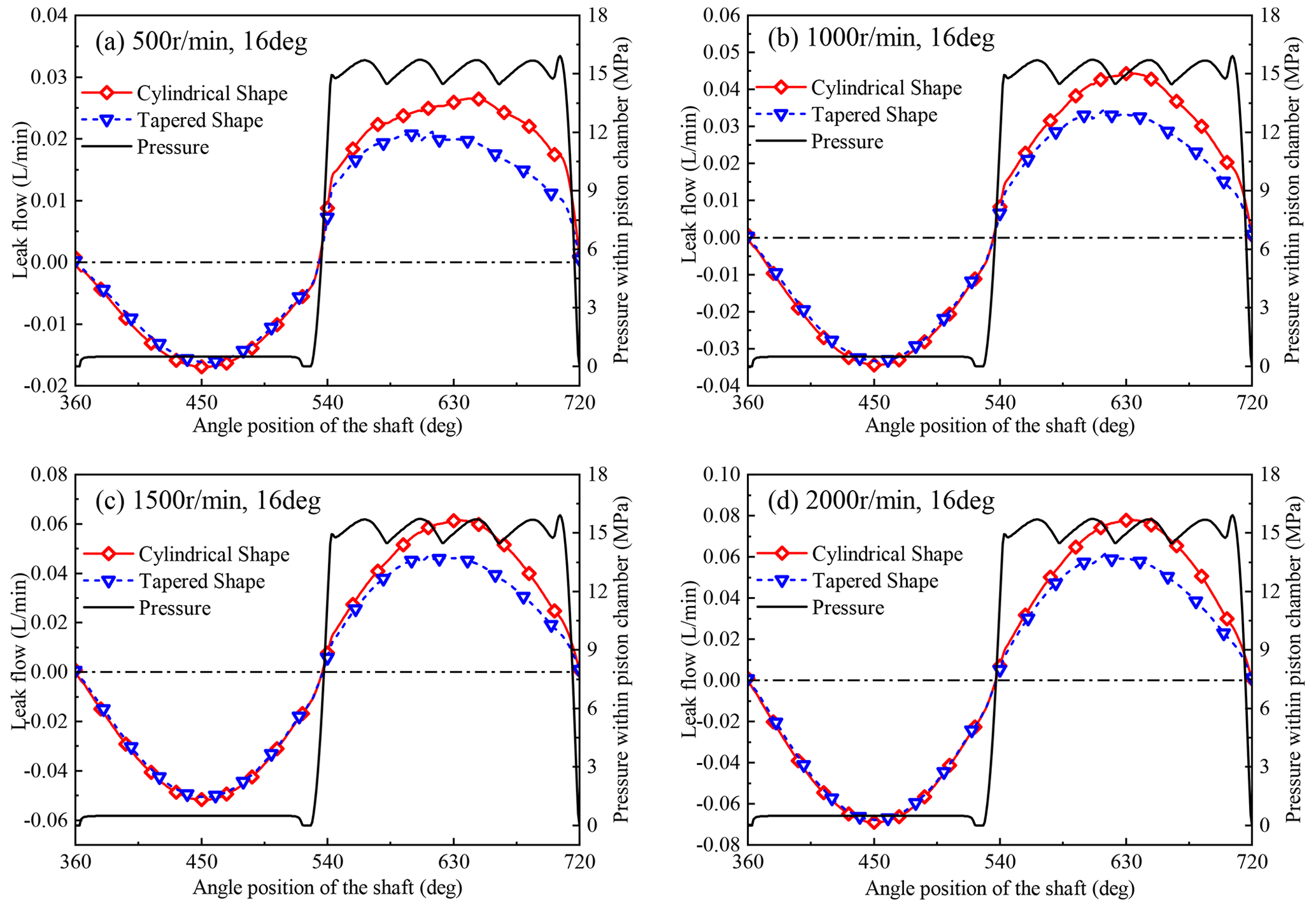
Figure 10Comparison of the leakage flow of the piston–cylinder pair with different piston bore shapes at the swash plate angle of 16∘, a load pressure of 15 MPa, and a different working speed: (a) 500 rpm; (b) 1000 rpm; (c) 1500 rpm; (d) 2000 rpm.
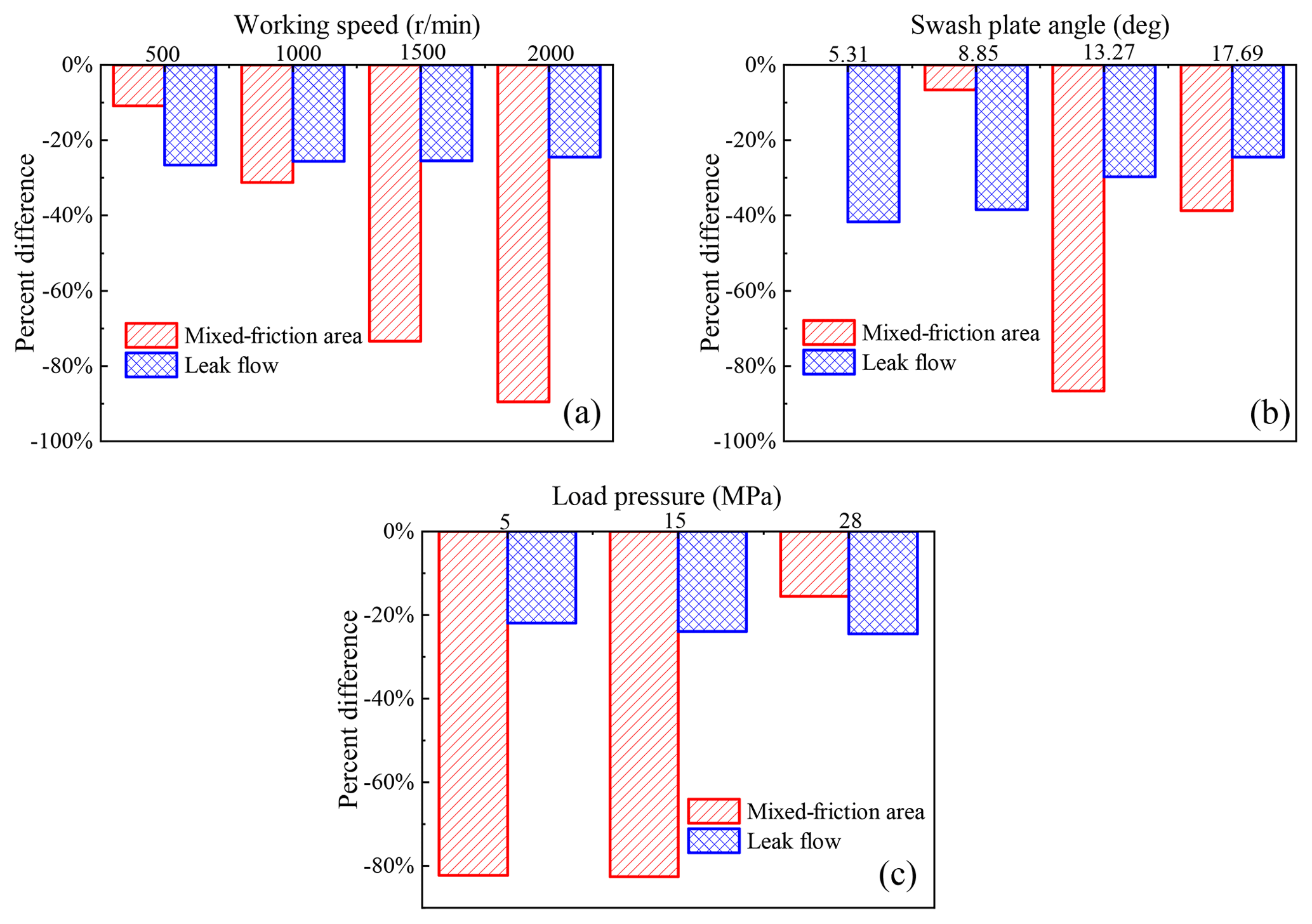
Figure 11The percent difference δcz over a wide range of operating parameters: (a) at a different working speed with 15 MPa and 16∘; (b) at a different swash plate angle with 28 MPa and 2000 rpm; (c) at a different load pressure with 2000 rpm and 17.69∘.
Figures 9 and 11 show that the piston–cylinder interface with the tapered-shape piston bore has a smaller mixed-friction area than the traditional piston–cylinder interface in the high-pressure side-working stroke under most working conditions. This means that the piston–cylinder interface with the tapered-shape piston bore has better lubricating and bearing performance. The relative change rate of the mixed-friction area between the tapered-shape piston bore and the cylindrical piston bore is greatly affected by the working conditions. Furthermore, the piston–cylinder interface with the tapered-shape piston bore has the effect of dramatically reducing the mixed-friction area under lower loads or higher displacements, and the relative change rate is proportional to the working speed. The highest relative change rate of the mixed-friction area is up to 89.5 % under the working condition of the swash plate angle of 16∘, load pressure of 15 MPa, and speed of 2000 rpm, and there is no mixed-friction area in the piston–cylinder interface under the working condition of the swash plate angle of 5.31∘, load pressure of 28 MPa, and speed of 2000 rpm. The relative change rate of the mixed-friction area is 0, as Fig. 11a shows.
Figures 10 and 11 show that the piston–cylinder interface with the tapered-shape piston bore has a smaller leakage flow than the traditional piston–cylinder interface over one shaft revolution under different working conditions. The dynamic pressure effect of the oil film of the piston–cylinder pair was strengthened by the tapered-shape structure, the distribution of the pressure field and the thickness field of the oil film is more uniform, and the local pressure peak is reduced. The differential pressure leakage and shear flow leakage are reduced under the combined effect. The leakage flow is less affected by the change in working conditions. Moreover, the maximum relative change rate of leakage flow is 41.7 % when the swash plate is 5.31∘, as shown in Fig. 11.
4.1 Experimental setup
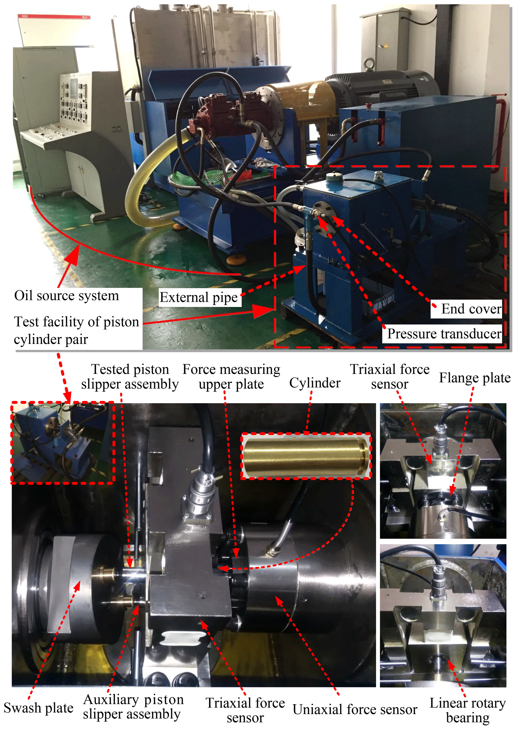
To experimentally investigate the tribological behavior of the piston–cylinder pair, the test facility shown in Figs. 12 and 13 was built to measure the friction within a single piston bore. As shown in Fig. 12, the piston bore is imitated by using a single cylinder with bushing pressed in place analogous to the design of an actual cylinder block with bushing within a real axial piston machine. The cylinder was mounted within a nearly frictionless linear rotary bearing. The tested piston–slipper assembly was placed within the piston bore of the cylinder. Below the tested piston–slipper assembly, an additional auxiliary piston–slipper assembly was placed within the piston bore of the pedestal connected to the housing. To simplify the positioning of the force sensors, the swash plate is rotating, analogous to an axial piston machine in wobble design. Once the cylinder was placed within the linear rotary bearing, two flange plates – the upper flange plate and the lower flange plate – were attached to the outside mounting groove of the linear rotary bearing to hold the bearing within the mounting hole of the triaxial force sensor. There is a tiny but large enough gap in the axial direction between the flange plates and the outside mounting groove of the linear rotary bearing, which avoids the transmission of the forces from bearing to flange plates in the axial direction and guarantees the exact and accurate measurement of the side forces exerted on the cylinder from the tested piston–slipper assembly via the triaxial force sensor. Simultaneously, on the right-hand side of the cylinder, two force-measuring plates were attached to the mounting groove of the cylinder. Analogously, due to the existence of the tiny but large enough gap in the axial direction between the two force-measuring plates and the mounting groove of the cylinder, the relatively small axial friction forces of the tested piston–cylinder pair exerted on the cylinder are sufficiently decoupled from the much larger side forces and transferred through the force-measuring plates to the uniaxial force sensor, realizing the exact and accurate measurement of the axial friction forces via the uniaxial force sensor.
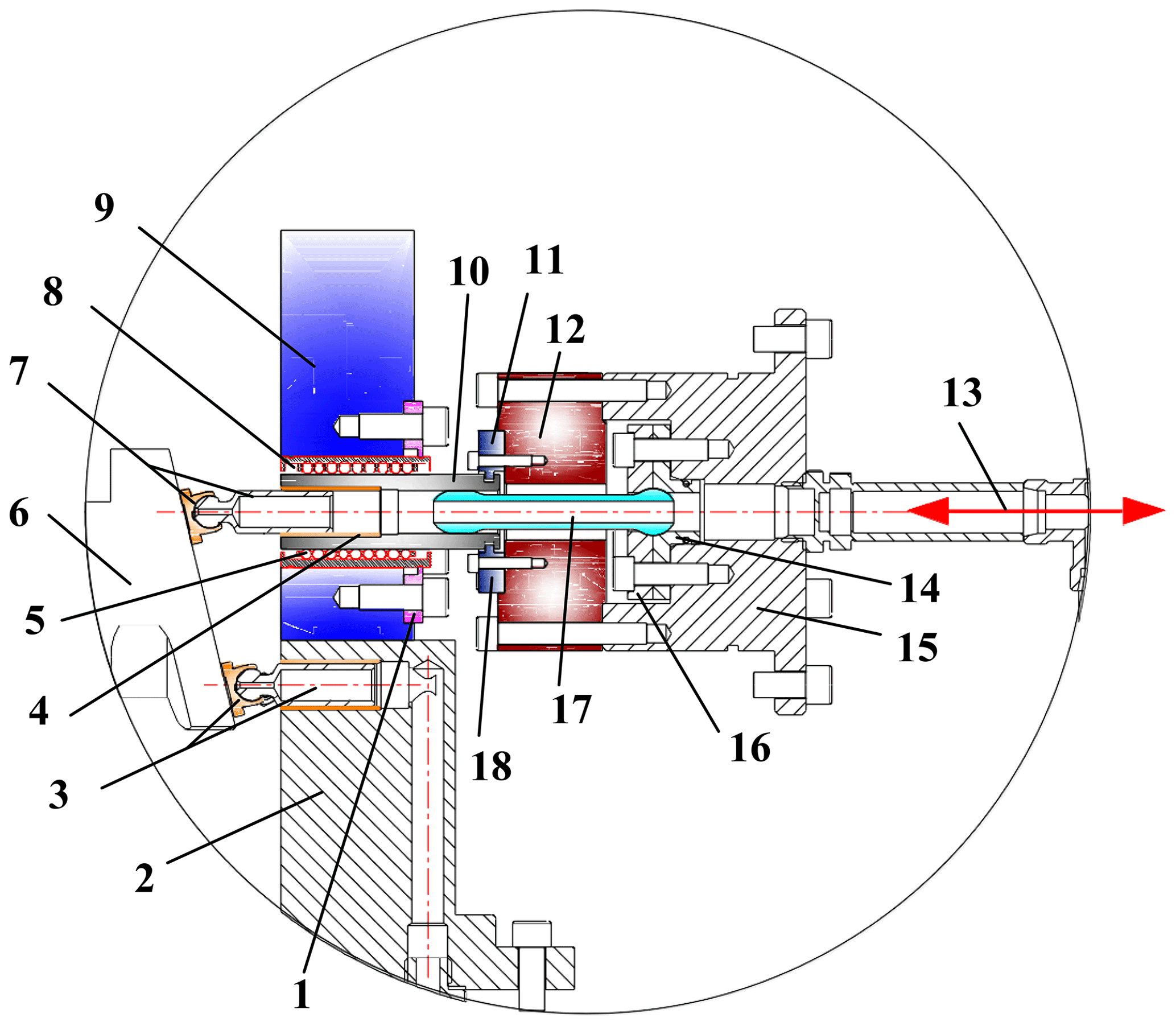
Figure 12Partial enlargement drawing of the decoupling test structure of the triaxial force arising in the tested piston–cylinder pair. 1. Flange plate. 2. Pedestal. 3. Auxiliary piston–slipper assembly. 4. Bushing. 5. Roll ball. 6. Swash plate. 7. Tested piston–slipper assembly. 8. Linear rotary bearing. 9. Triaxial force sensor. 10. Cylinder. 11. Force-measuring upper plate. 12. Uniaxial force sensor. 13. Inlet and outlet ports of oil. 14. Seat cover. 15. End cover. 16. Pressing plate. 17. Oil conduit. 18. Force-measuring lower plate.
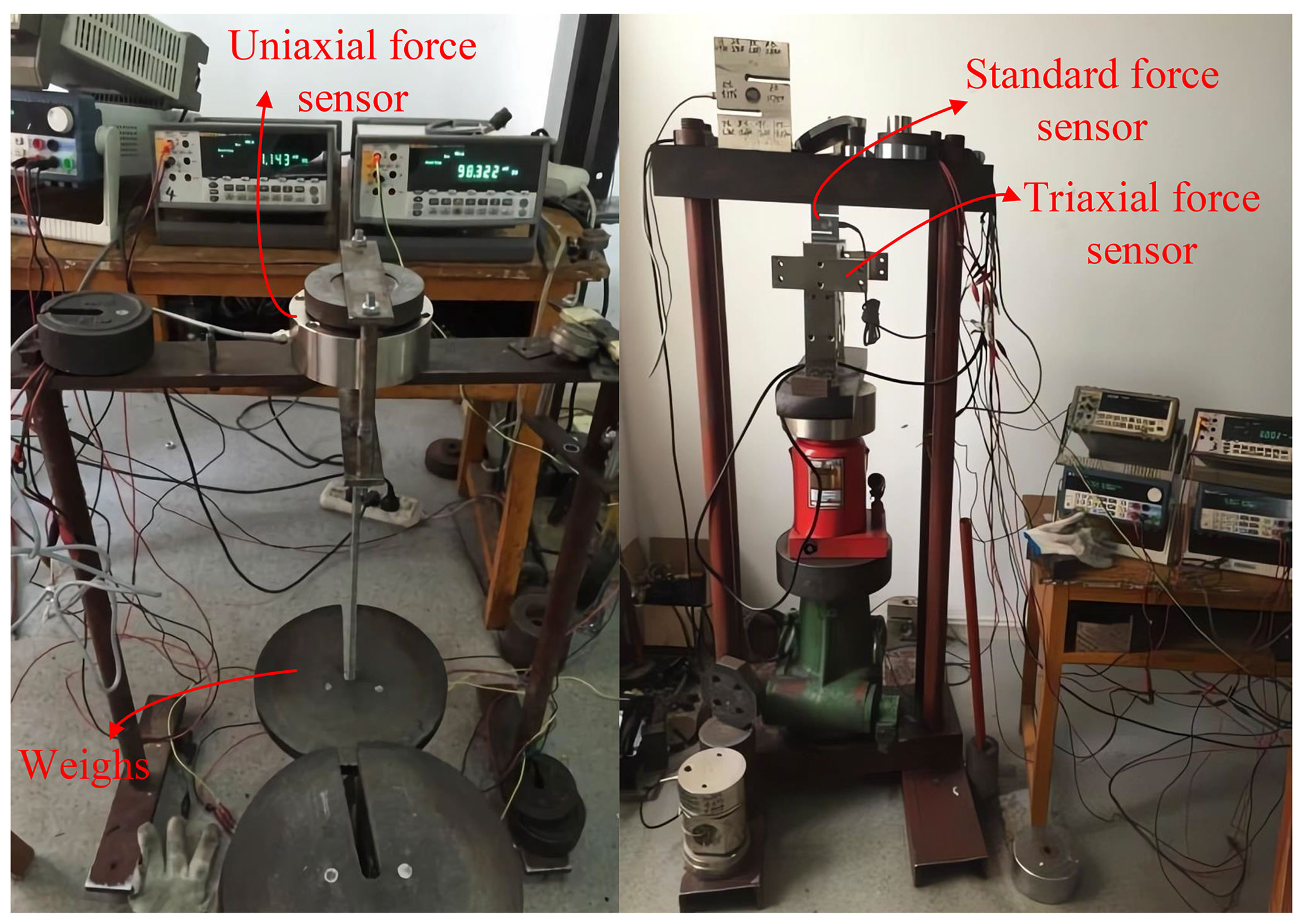
Figure 13Force sensor calibration experiment: the left shows calibration using weights, and the right shows calibration using a standard force sensor.
The triaxial force sensor and the uniaxial force sensor, respectively, were fixed on the pedestal and the end cover, which were both connected to the housing. Between the cylinder and the end cover, an additional part was placed which functions as an oil conduit passing through the center opening of the uniaxial force sensor (Fig. 12). The oil conduit was used to supply a constant fluid pressure within the piston bore via the inlet and outlet ports of oil shown in Fig. 12 and an external oil source system shown in Fig. 13. The ball joint on the right-hand side of the oil conduit guarantees the self-adapting placement in the cylinder and the housing, which is formed by the oil conduit and the pressing plate as well as the seat cover connected to the end cover. The sealing between the oil conduit and the cylinder and between the pressing plate and the seat cover was achieved by the surface contact, which is easier to handle. The oil conduit, except for negligible low viscous friction forces due to leakage between the oil conduit and the cylinder, does not transfer friction forces to the cylinder. In this way the uniaxial force sensor is only charged by the friction forces of the tested piston–cylinder pair.
The uniaxial force sensor and the triaxial force sensor installed within the test rig are both customized, so the sensors need to be calibrated before the test. The calibration device for the force sensor is shown in Fig. 13. The sensors are calibrated using weights and standard force sensors, respectively. The former method loads weights onto the force sensor and checks whether the output of the tested sensor matches the weights. The latter method stacks the force sensor to be calibrated with a standard force sensor on a hydraulic jack and fixes the upper end of the stacked sensors before applying loads to the force sensors through the jack. In addition to verifying the consistency of the output between the tested sensor and the standard force sensor, it is also necessary to verify the normalcy of the output curve of the tested sensor. The test results are shown in Fig. 14, and it can be seen from the figure that the tested sensor has good linearity, high sensitivity, and a small cross-effect.
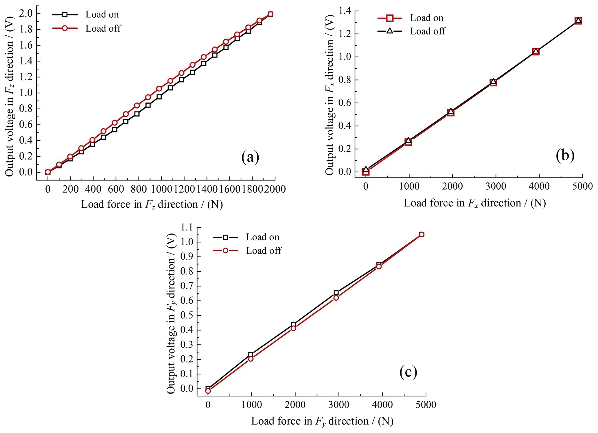
Figure 14The calibration result of the force sensor: (a) the output in the Fz direction; (b) the output in the Fx direction; (c) the output in the Fy direction.
Due to the friction of the piston–cylinder pair mainly occurring on the high-pressure side of the piston travel, based upon this consideration, the cylinder bore was always charged with high-pressure hydraulic oil via the inlet and outlet ports connected to the external oil source system through a four-way pipe fitting. A pressure transducer was installed on the four-way pipe fitting to measure the pressure within the cylinder bore. Therefore, the tested piston is able to work as a motoring piston, the piston bore suctions the high-pressure oil and a pumping piston, and the piston discharges the high-pressure oil. The piston chambers of the tested piston–cylinder pair and the auxiliary piston–cylinder pair were connected to an external pipe through the four-way pipe fitting so as to utilize the piston travel in the opposite direction to avoid the pressure shock (Fig. 15).
4.2 Test specimen preparation
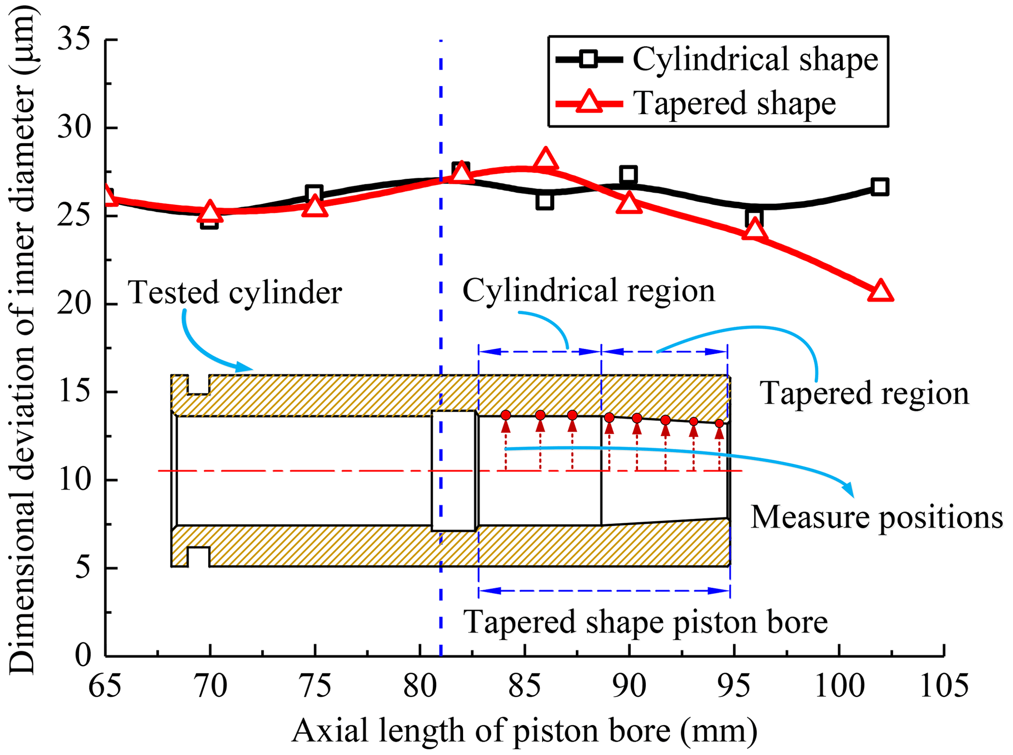
Two kinds of cylinders were investigated at the test facility of the piston–cylinder pair. Both cylinders are made of brass, with the cylinder bore analogous to the piston bore within the brass bushing mounted into a steel or cast-iron cylinder of a real axial piston machine, and the piston is made of steel. One cylinder has an industrial cylindrical-shape piston bore surface, the other one has the same macro-geometric sizes, but a micro-geometric tapered-shape surface of the piston bore has been realized with a high-performance CNC machine. Figure 16 illustrates the manufactured cylinder with the tapered-shape piston bore, which consists of the cylindrical region and the tapered region, just like the numerical optimization results of the tapered-shape surface in the previous statement. However, the lubricating gap between the piston and the piston bore has been increased to simplify the manufacturing process. The measurement positions and the corresponding measurement results of the dimensional deviation of the inner diameter of the piston bore for the two kinds of investigated cylinders are shown in Fig. 16.
4.3 Exemplary measurement results
To simplify the comparison of measurements under different pressure levels and to make the results more intuitive, it is common to perform dimensionless normalization of the experimental data. The total axial friction force Ff of the piston–cylinder pair is based on the pressure force Fp acting on the end of the piston, i.e., . This means that the closer the value is to 0, the smaller the friction force is. The friction values are shown as the following Figs. 17 and 18.
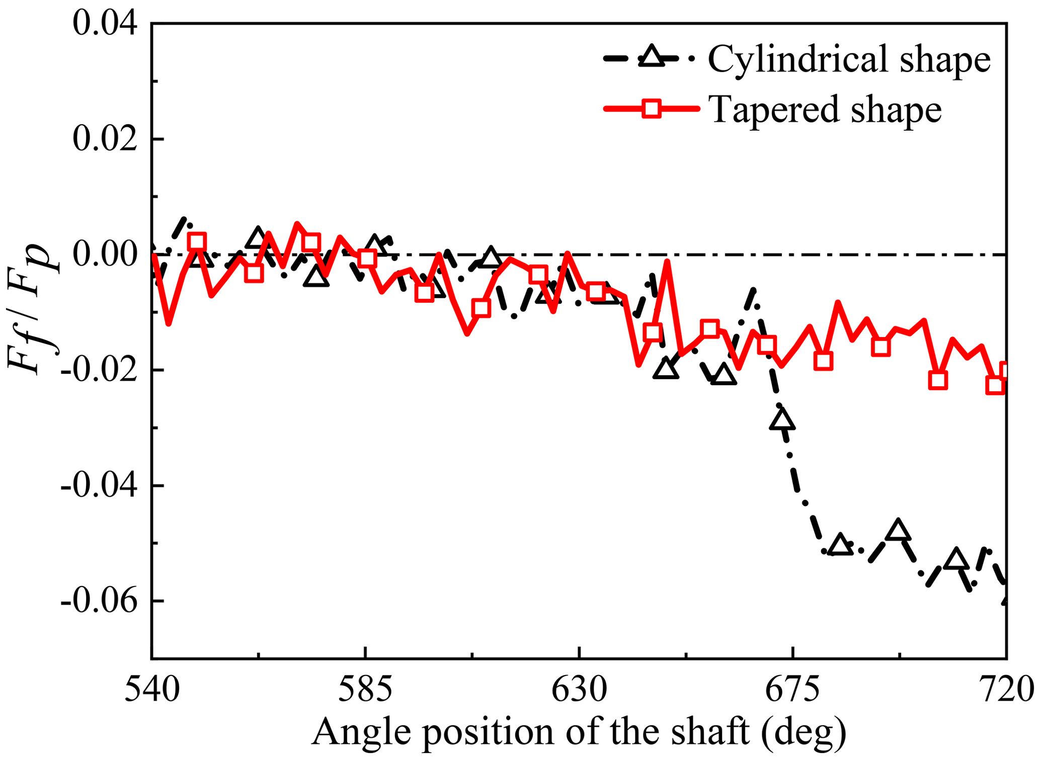
Figure 17Comparison of friction forces of the piston–cylinder pair under the conditions of pressure 5 MPa and speed 500 rpm.
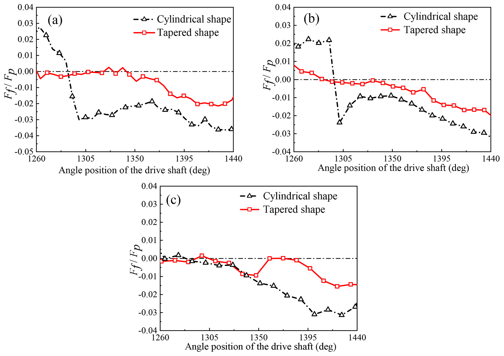
Figure 18Comparison of friction forces of the piston–cylinder pair under the conditions of pressure 15 MPa and different speeds: (a) 1000 rpm; (b) 1500 rpm; (c) 2000 rpm.
Figures 17 and 18 apparently show that, compared with the traditional piston–cylinder pair with a cylindrical-shape piston bore, the friction forces of the piston–cylinder pair with the tapered-shape piston bore were dramatically reduced. The comparison of friction forces at different speeds in Fig. 18 also shows that the friction forces of the piston–cylinder pair decrease with the increase in the shaft working speed of an axial piston motor. Furthermore, the variation of the friction force is also smaller during the working cycle, which means that there is less abrupt change in the friction force. This is beneficial for prolonging the service life of the piston–cylinder pair.
As one of the important components of the hydraulic system, the axial piston motor also needs to adapt to the requirements of modern industrial production, and the performance improvement of the piston–cylinder pair, one of the key friction pairs within piston machines, directly affects the efficiency and service life of the axial piston motor. Insufficient research has been conducted on axial piston motors due to the fact that related studies often focus on axial piston pumps as the research object, while axial piston motors are widely used in the aerospace and construction machinery fields as the energy conversion device. It is necessary to analyze and design the structure of the piston–cylinder interface suitable for piston motors to improve its working efficiency and service life. To investigate the influence of the tapered piston bore surface on the performance of the piston–cylinder pair, an elastic–hydrodynamic fluid–structure interaction simulation model was established. Firstly, the model was used to calculate a series of tapered piston bore surfaces with different axial distribution length ratios under different displacement conditions. From Fig. 8, it can be seen that the relative ratio of the mixed-friction area reaches almost the same minimum at the 49.44 % and 67.52 % axial distribution length ratios of the tapered-shape surface of the piston bore. Considering manufacturing and sealing aspects, the value of 49.44 % is determined as the optimal value in this paper. In addition, the mixed-friction area within a large range of axial distribution length ratios between 0.45 and 0.7 is relatively small and stable. This means that the effective range of the antifriction effect of the tapered piston bore surface is wide and less affected by working conditions. Therefore, the optimal value adopted in this paper has a high reference value in practical engineering. Due to the structural similarities of the axial piston motor, a larger effective range means that the axial distribution length ratio can be adjusted appropriately according to the needs of different structural-size axial piston motors without greatly affecting the antifriction and leakage reduction effect of the tapered piston bore surface. From the simulation results, it can be seen that the mixed-friction area increases with the increase in working pressure and displacement and decreases with the increase in shaft working speed, while the leakage losses increase with the increase in displacement and shaft working speed. In addition, compared with the traditional cylindrical piston bore, the tapered piston bore surface can effectively reduce the friction losses and leakage losses of the piston–cylinder pair.
To verify the accuracy of the numerical model, a test rig was developed to study the frictional characteristics of the piston–cylinder pair. The platform was used to investigate the variation of the frictional force of the piston when working in the piston bore with a different surface. The numerical simulation results in Figs. 9 and 11a show that, with the increase in working speed from 500 to 2000 rpm, the mixed-friction area in the piston–cylinder interface gradually decreases, which agrees with the change law of measurement friction forces with respect to the working speed in Fig. 18. Compared with the lower speeds of 500 and 1000 rpm, on the other hand, the numerical simulation results show that the tapered-shape piston bore significantly reduces the mixed-friction area through the overall piston travel. It can be seen from Figs. 9, 17, and 18 that the mixed-friction area obtained from the numerical simulation can exactly reflect the actual variation law of friction forces within real piston–cylinder pairs.
In this work, the influence of a tapered-shape micro-geometric design of the piston bore surface profile on the performance of the piston–cylinder pair in piston motors was investigated through a developed elastic–hydrodynamic fluid–structure interaction simulation model and a new test facility of the piston–cylinder pair.
The tapered-shape piston bore is characterized by the continuous and gradual diameter reduction in the piston bore toward the housing in axial piston motors. Considering manufacturability and maintaining the essential seal length of the cylindrical-shape surface of the piston bore, the piston bore with the tapered-shape surface axial distribution length ratio of 49.44 % of the overall length of the piston bore is first determined to be the relatively optimized one through the simulation comparison. The mixed-friction area and the leakage flow of both piston–cylinder interfaces are simulated and analyzed under different working conditions: the results showed that the tapered-shape piston bore outperforms the cylindrical piston bore. The relative change rate of the mixed-friction area between the tapered-shape piston bore and the cylindrical piston bore is greatly affected by the working conditions, and the highest relative change rate can reach up to 89.5 %, while the leakage flow is less affected by the change in working conditions and the maximum relative change rate of the leakage flow is 41.7 %. The test rig can accurately measure the frictional force of the piston–cylinder pair when working with different piston bore surfaces, which reflects the frictional loss of the piston–cylinder pair. The experimental results show that the tapered piston bore surface can effectively reduce the frictional loss under different working conditions, and the results are consistent with the simulation results.
The comparison of numerical simulation results with measurements of the piston friction force has demonstrated that the piston–cylinder pair with the optimized tapered-shape piston bore is found to be particularly suitable for a piston motor, achieving a significant reduction in leakage flow, friction force, and energy dissipation. It provides guidance for the design of energy-efficient and longer-service-life axial piston motors.
| Flx, Fly | The total load forces of the piston–slipper assembly in the x and y directions |
| Mlx, Mly | The external moments acting on the piston slipper assembly in the x and y directions |
| Fn | The reaction force exerted on the slipper by the swash plate |
| Ffs | The friction force of the slipper swash plate pair |
| Fe | The centrifugal force of the piston–slipper assembly |
| Lcc | The distance between the center of mass of the piston–slipper assembly and the ball center of the piston head |
| e1, e2, e3, e4 | The distance between the center points of the piston bore and the piston by taking two cross sections of the piston cut from the two end-faces of the bushing |
| hp | The local oil film depth |
| lf | The initial gap length between the piston and bushing |
| φpc | The angular position of the oil film in the circumferential direction around the piston |
| Δhp | The contribution to the oil film depth due to the surface deformation of the solid boundary at the friction interface of the piston–cylinder pair |
| rc, rp | The inner radius of the piston bore and the outer radius of the piston |
| μ | The viscosity of the oil film of the piston–cylinder pair |
| p | The pressure of the oil film of the piston–cylinder pair |
| ωp | The angular speed of the piston revolving on its axis |
| ζ | The viscosity–pressure coefficient |
| μ0 | The viscosity of oil at 40 ∘C and 1 atm |
| Δhp | The array containing the elastic deformation of each of the surface nodes of the piston–cylinder solid domain |
| pref | The reference pressure acting on each face of the solid surface defining the fluid film boundary |
| pi | The external actual fluid pressure acting on each of the N faces of the boundary surface |
| DMi | The ith face deformation matrix containing the elastic deformation of all the surface nodes |
| Δx, Δy | The angle interval and the length interval of the fluid film pressure field nodes |
| hcd | The minimum value of the oil film thickness of the piston–cylinder pair |
| Ffpm | The mixed-friction force |
| τfpm | The friction shear stress of the unit body at the friction interface |
| Am | The mixed-friction area |
| Rqp, Rqc | The root-mean-square deviation of the surface roughness of the piston surface and the piston bore surface |
| Rap, Rac | The arithmetic average deviation of the surface roughness of the piston surface and the piston bore surface |
| ζp | The film thickness ratio |
| Nm | The number of film thickness field nodes lower than the minimum film depth |
| Ffpx, Ffpy | The total viscous friction forces acting on the different surfaces |
| τpx, τpy | The viscous shear stresses in the circumferential and axial directions |
| vx, vy | The velocity of the local point of the oil film along the x-axis and y-axis directions |
| Qpc | The instantaneous leakage flow |
| ζc, ζz | The calculated value of the piston–cylinder pair with the tapered-shape piston bore and the traditional cylindrical-shape piston bore |
| Ff | The total axial friction force of the piston–cylinder pair |
| Fp | The pressure force acting on the end of the piston |
The data used in this study did not originate from the internet but rather from the author's simulation and experimental results. If necessary, please feel free to contact the corresponding author, Minhu (minhu@hfut.edu.cn), or the first author, Rui Liu (lryyddy@gmail.com), for further information.
RL was responsible for collecting the research literature, organizing the paper structure, and writing the paper. YZ and MH provided the research direction of this paper and performed all of the experiments. LW made part of the figures. HZ checked the procedure. MH, YZ, and CL finalized the paper and supervised the work.
The contact author has declared that none of the authors has any competing interests.
Publisher’s note: Copernicus Publications remains neutral with regard to jurisdictional claims in published maps and institutional affiliations.
The authors wish to thank Hefei University of Technology for its support.
This research has been supported by the National Natural Science Foundation of China (grant nos. 52075139, 52005144, and 51905139).
This paper was edited by Zi Bin and reviewed by four anonymous referees.
Chen, Y., Zhang, J., Xu, B., Chao, Q., and Liu, G.: Multi-objective optimization of micron-scale surface textures for the cylinder/valve plate interface in axial piston pumps, Tribol. Int., 138, 316–329, https://doi.org/10.1016/j.triboint.2019.06.002, 2019. a
Ernst, M. and Ivantysynova, M.: Cylinder Bore Micro-Surface Shaping for High Pressure Axial Piston Machine Operation Using Water as Hydraulic Fluid, in: ASME/BATH 2017 Symposium on Fluid Power and Motion Control, Fluid Power Systems Technology, Florida, USA, 16–19 October 2017, ASME, V001T01A043, https://doi.org/10.1115/fpmc2017-4285, 2017. a
Ernst, M. and Ivantysynova, M.: Axial Piston Machine Cylinder Block Bore Surface Profile for High-Pressure Operating Conditions with Water as Working Fluid, 2018 Global Fluid Power Society PhD Symposium (GFPS), Samara, Russia, 18–20 July 2018, IEEE, 1–7, https://doi.org/10.1109/GFPS.2018.8472386, 2018. a
Ernst, M., Vacca, A., Ivantysynova, M., and Enevoldsen, G.: Tailoring the Bore Surfaces of Water Hydraulic Axial Piston Machines to Piston Tilt and Deformation, Energies, 13, 5997, https://doi.org/10.3390/en13225997, 2020. a
Ernst, M., Ivantysynova, M., and Vacca, A.: Shaping the Piston–Cylinder Interfaces of Axial Piston Machines for Running in the High-Pressure Regime with Water as the Hydraulic Fluid, P. I. Mech. Eng. C-J. Mec., 236, 6851–6872, https://doi.org/10.1177/09544062211068643, 2022. a
Fang, Y. and Shirakashi, M.: Mixed Lubrication Characteristics Between the Piston and Cylinder in Hydraulic Piston Pump-Motor, J. Tribology-T. ASME, 117, 80–85, https://doi.org/10.1115/1.2830610, 1995. a
Ivantysynova, M.: An investigation of viscous flow in lubricating gaps, Slovak University of Technology, PhD thesis, Czechoslovakia, 1983. a
Ivantysynova, M. and Lasaar, R.: An Investigation into Micro- and Macrogeometric Design of Piston/Cylinder Assembly of Swash Plate Machines, International Journal of Fluid Power, 5, 23–36, https://doi.org/10.1080/14399776.2004.10781181, 2004. a, b, c
Jia, H., Zhou, Z., Yin, B., Zhou, H., and Xu, B.: Influence of microdimple on lubrication performance of textured plunger pump, Ind. Lubr. Tribol., 73, 563–571, https://doi.org/10.1108/ILT-07-2020-0259, 2021. a
Li, M., Foss, R., Stelson, K. A., Ven, J., and Barth, E. J.: Design, Dynamic Modeling, and Experimental Validation of A Novel Alternating Flow Variable Displacement Hydraulic Pump, IEEE-ASME T. Mech., 24, 1294–1305, https://doi.org/10.1109/TMECH.2019.2906859, 2019. a
Lyu, F., Zhang, J., Sun, G., Xu, B., Pan, M., Huang, X., and Xu, H.: Research on wear prediction of piston/cylinder pair in axial piston pumps, Wear, 456–457, 203338, https://doi.org/10.1016/j.wear.2020.203338, 2020. a
Ma, X., Wang, Q. J., Lu, X., and Mehta, V. S.: Piston surface design to improve the lubrication performance of a swash plate pump, Tribol. Int., 132, 275–285, https://doi.org/10.1016/j.triboint.2018.12.023, 2019. a
Manring, N. D.: Friction Forces Within the Cylinder Bores of Swash-Plate Type Axial-Piston Pumps and Motors, J. Dyn. Syst.-T. ASME, 121, 531–537, https://doi.org/10.1115/1.2802507, 1999. a
Murrenhoff, H.: Recent sustainability related research results in fluid power, in: Proceedings of 2011 International Conference on Fluid Power and Mechatronics, Beijing, China, 17–20 August 2011, IEEE, 991–1001, https://doi.org/10.1109/FPM.2011.6045907, 2011. a
Murrenhoff, H. and Scharf, S.: Wear and Friction of ZRCg-Coated Pistons of Axial Piston Pumps, International Journal of Fluid Power, 7, 13–20, https://doi.org/10.1080/14399776.2006.10781254, 2006. a, b
Pelosi, M.: An investigation of the fluid-structure interaction of piston/cylinder interface, PhD thesis, Purdue University, USA, 158 pp., ISBN 9781267775719, 2012. a
Pelosi, M. and Ivantysynova, M.: Surface Deformations Enable High Pressure Operation of Axial Piston Pumps, in: ASME 2011 Dynamic Systems and Control Conference and Bath/ASME Symposium on Fluid Power and Motion Control, Dynamic Systems and Control Division, Virginia, USA, 31 October–2 November 2011, 193–200, https://doi.org/10.1115/dscc2011-5979, 2011. a
Sarode, S. and Shang, L.: Novel Pressure Adaptive Piston Cylinder Interface Design for Axial Piston Machines, in: ASME/BATH 2019 Symposium on Fluid Power and Motion Control, Fluid Power Systems and Technology Division, Florida, USA, 7–9 October 2019, V001T01A018, https://doi.org/10.1115/fpmc2019-1645, 2019. a
Shang, L. and Ivantysynova, M.: Scaling Criteria for Axial Piston Machines Based on Thermo-Elastohydrodynamic Effects in the Tribological Interfaces, Energies, 11, 3210, https://doi.org/10.3390/en11113210, 2018. a
Shang, L. and Ivantysynova, M.: Thermodynamic Analysis on Compressible Viscous Flow and Numerical Modeling Study on Piston/Cylinder Interface in Axial Piston Machine, JFPS International Journal of Fluid Power System, 11, 117–123, https://doi.org/10.5739/jfpsij.11.117, 2019. a
Wondergem, A. M. and Ivantysynova, M.: The Impact of the Surface Shape of the Piston on Power Losses, in: 8th FPNI Ph.D Symposium on Fluid Power, Fluid Power Systems Technology, Lappeenranta, Finland, 11–13 June 2014, V001T02A008, https://doi.org/10.1115/fpni2014-7843, 2014. a
Xu, B., Zhang, J. H., and Yang, H. Y.: Investigation on structural optimization of anti-overturning slipper of axial piston pump, Sci. China Technol. Sc., 55, 3010–3018, https://doi.org/10.1007/s11431-012-4955-x, 2012. a
Xu, B., Hu, M., Zhang, J., and Mao, Z.: Distribution characteristics and impact on pump's efficiency of hydro-mechanical losses of axial piston pump over wide operating ranges, J. Cent. South Univ., 24, 609–624, https://doi.org/10.1007/s11771-017-3462-4, 2017. a
Yamaguchi, A. and Tanioka, Y.: Motion of Pistons in Piston-Type Hydraulic Machines, Bulletin of JSME, 19, 402–419, https://doi.org/10.1299/jsme1958.19.402, 1976. a
Ye, S., Zhang, J., Xu, B., Zhu, S., Xiang, J., and Tang, H.: Theoretical investigation of the contributions of the excitation forces to the vibration of an axial piston pump, Mech. Syst. Signal Pr., 129, 201–217, https://doi.org/10.1016/j.ymssp.2019.04.032, 2019. a
Yin, B., Jiang, Y., Xu, B., Jia, H., and Wang, X.: Study on Tribological Properties of Laser-Textured Plunger in Methanol Engine, Int. J. Automot. Techn., 22, 1045–1055, https://doi.org/10.1007/s12239-021-0094-3, 2021. a
Zhang, J., Chen, Y., Xu, B., Chao, Q., Zhu, Y., and Huang, X.: Effect of surface texture on wear reduction of the tilting cylinder and the valve plate for a high-speed electro-hydrostatic actuator pump, Wear, 414–415, 68–78, https://doi.org/10.1016/j.wear.2018.08.003, 2018. a
Zhang, J., Qiu, X., Gong, X., and Kong, X.: Wear behavior of friction pairs of different materials for ultra-high-pressure axial piston pump, P. I. Mech. Eng. E-J. Pro., 233, 945–953, https://doi.org/10.1177/0954408918820728, 2019. a
Zhang, J., Liu, B., LÜ, R., Yang, Q., and Dai, Q.: Study on Oil Film Characteristics of Piston-Cylinder Pair of Ultra-High Pressure Axial Piston Pump, Processes, 8, 68, https://doi.org/10.3390/pr8010068, 2020. a, b
Zhang, J., Lyu, F., Xu, B., Huang, W., Wu, W., Guo, Z., Xu, H., and Huang, X.: Simulation and experimental investigation on low wear rate surface contour of piston/cylinder pair in an axial piston pump, Tribol. Int., 162, 107127, https://doi.org/10.1016/j.triboint.2021.107127, 2021. a
- Abstract
- Introduction
- Numerical approach
- Numerical analysis of the performance of the tapered-shape piston bore
- Friction force measurement
- Discussion
- Conclusions
- Appendix A: Nomenclature of the symbols
- Data availability
- Author contributions
- Competing interests
- Disclaimer
- Acknowledgements
- Financial support
- Review statement
- References