the Creative Commons Attribution 4.0 License.
the Creative Commons Attribution 4.0 License.
 | 12 Apr 2023
Surface quality improvement for 316L additive manufactured prototype based on magnetorheological polishing
Na She
Tao Gong
Minrui Lu
Yongchao Xu
Xiaodong Peng
Additive manufacturing has attracted increasing attention in recent years due to its flexibility and near-net shaping advantages. Although recent advancements in metal additive manufacturing accuracy have met the post-processing requirement for dimensional tolerance, the finishing post-processing of functional surfaces must be further investigated in conjunction with material characteristics. This research aims to investigate the use of a flexible process in the polishing of additive molding samples. As an example, the surface of a 316L stainless steel sample formed by powder bed laser melting was polished using magnetorheological polishing technology. Magnetic field simulation was used to create a longitudinally staggered magnetorheological polishing tool. Surface roughness and residual stress were studied with process parameters such as abrasive content, magnetic particle content, machining gap, and spindle speed. Results show that the polishing effect is better at 4 % and 40 % abrasive and magnetic particles, respectively. The surface roughness Ra is 99 nm when the working gap is 0.6 mm, the surface roughness Ra value is the lowest when the spindle speed is 600 r min−1. The surface roughness was reduced to 61.43 nm after polishing the sample under improved processing conditions (4 % abrasive, 40 % magnetic, 0.6 mm working clearance, 600 r min−1 spindle speed). A nano-scale smooth surface can be obtained by powder bed laser melting and magnetorheological polishing of 316L stainless steel.
- Article
(7695 KB) - Full-text XML
- BibTeX
- EndNote


Additive manufacturing (AM) technologies have attracted increased research attention and experienced rapid development in the past 20 years (Aboulkhair et al., 2019; Herzog et al., 2016; Li et al., 2019; Malaga et al., 2022). 316L stainless steel is one of the most commonly used alloys in biomedical applications, including surgical instruments, orthopedic implants, fixed devices, orthodontics, and pharmaceutical equipment. The wide application of stainless steel can be attributed to its reasonable cost, easy manufacture, biocompatibility, sufficient mechanical strength, and corrosion resistance (Lodhi et al., 2019; Roland et al., 2006). Among various AM technologies, typical laser powder bed fusion (L-PBF; also known as selective laser melting) is used as an example (Yadroitsev et al., 2007). L-PBF parts are comparable with or even better than conventional cast or forged parts in terms of certain mechanical properties (e.g., tensile strength, yield strength, elongation, hardness) (Atabay et al., 2020; Chlebus et al., 2011); however, microcracking slagging, powder adhesion, and periodization occur during the part manufacturing process. The surface roughness (Ra) of the parts is large, causing the degradation of the mechanical properties and surface roughness of additive manufactured 316L parts (Nafar Dastgerdi et al., 2022; Sanaei and Fatemi, 2020). The surface of the part is rough, usually greater than 100 µm, which is difficult to directly meet the application requirements. For example, in biomedicine, the surface should be smooth and non-abrasive, the Ra value should be no more than 0.1 µm, and the surface should be free of oxide, cracks, depressions, front edge, speculation, and other defects and free of mosaicism. At present, the surface treatment process of L-PBF molding parts mainly includes machining, chemical polishing, laser polishing, and heat treatment (Mariani et al., 2021; Souza et al., 2021; Bezuidenhout et al., 2020). Bagehorn et al. (2017) machined Ti-6Al-4V parts manufactured by additive manufacturing, and the roughness was reduced to 1 µm. Neda et al. (2017) combined chemical polishing and abrasive polishing for surface finish control of additive manufactured Inconel 625 parts, and the surface roughness was reduced from 17.4 to 14.2 µm. Chen et al. (2021) investigated the effect of laser polishing on the organization and mechanical properties of 316L stainless steel prepared by laser powder bed fusion (Sa = 0.65 µm); the surface roughness of 316L (Sa = 4.84 µm) was significantly reduced. Existing surface polishing techniques can cause sub-surface damage, high residual stresses, and other problems, and the surface roughness is still insufficient for scenario-specific applications.
In the field of non-traditional polishing, magnetorheological polishing (MRP) is based on the special rheological properties of MR fluid (Sidpara et al., 2009; Ashtiani et al., 2015; Chen et al., 2022), which is prepared by adding polishing abrasives (such as diamond, boron oxide, alumina, and cerium oxide) to MR fluid (Nagdeve et al., 2018); by applying a certain magnetic field, the polishing fluid rapidly changes from Newton fluid to Bingham plastic fluid in milliseconds. The shear stress increases rapidly, forming a polishing band or pad, and the abrasive grains achieve polishing by scratching and plowing the surface of the workpiece. Flexible MRP has the characteristics of high accuracy of processed surface shape, small surface roughness, easy control of the process, and low surface damage (Li et al., 2016; Wan et al., 2021; Yadav and Singh, 2019). MRP technology has been widely studied. Xu et al. (2021) improved the surface accuracy of tungsten alloy aspheric dies to less than 200 nm and reduced the surface roughness Ra to about 1 nm by combining ultra-precision grinding and oblique axis MRP techniques. Ghosh et al. (2021) used a wheel-type MRP process with a working gap of 2 mm, grinding wheel speed of 320 rpm, and feed rate of 11 mm min−1; the surface roughness of 15.5 nm was achieved on oxygen-free high-conductivity (OFHC) copper. Barman and Das (2018) carried out nano-polishing of biological titanium alloys by preparing magnetorheological fluid with different components. The surface roughness Ra was reduced to 10 and 70 nm, and the wear resistance and service life of the polished parts were improved.
The existing theoretical system of MRP is mainly for hard and brittle non-metallic materials, and the metal materials are mainly concentrated in traditional castings or forgings; in particular, the polishing theoretical system of additive metal parts needs to be explored. In this research, the MRP tool is designed, and the magnetic circuit is simulated and analyzed for L-PBF formation of 316L stainless steel samples. The effect of MRP process parameters (abrasive content, magnetic particle content, working gap, and polishing speed) on the surface roughness of L-PBF-formed 316L stainless steel samples is investigated, and high-quality polishing of the samples is accomplished.
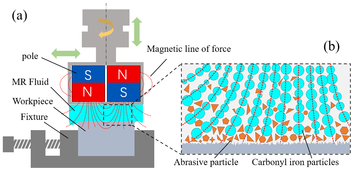
The principle of MRP is depicted in Fig. 1a. The cylindrical and axial magnetized permanent magnet is fixed on the machining spindle, and the sample is fixed under the permanent magnet by a fixture. The MRP fluid is in the machining gap between the permanent magnet and the sample. The permanent magnet pole is combined according to a certain rule, and magnetic field is generated to make the polishing fluid form a flexible polishing pad. In magnetorheological processing, the polishing solution is a mixture of magnetic particles (hydroxyl iron powder) and non-magnetic liquids, such as silicone oil and corundum abrasive particles. When the magnetic field is not applied to the polishing solution, the magnetic particles and abrasive particles are randomly dispersed. When the magnetic field is applied, the magnetic particles of the polishing fluid are arranged along the magnetic induction line to form a magnetic chain, and the abrasive particles are clamped by the chain structure. When the polishing pad moves with the sample, the abrasive particles remove the material on the sample surface, as depicted in Fig. 1b.
In the MRP process, the gradient magnetic field greatly affects the strength and shape of the magnetic chain during polishing and then affects the surface roughness of the sample after processing. Magnetic pole distribution is the main factor affecting the gradient magnetic field distribution. Therefore, appropriate magnetic pole arrangement for MRP should be selected. Four N30 cylindrical Nd-Fe-B permanent magnets with the size of Φ10 mm × 20 mm are selected for combined superposition, the magnetic poles are arranged, and the magnetic field is simulated.

Figure 2Cloud chart of scalar magnetic induction intensity with different magnetic pole spacing under natural arrangement.
Under the natural arrangement of magnetic poles, different magnetic pole spacings are used for simulation: 0.5, 1.0, and 1.5 mm. The scalar magnetic induction intensity program with different magnetic pole spacing is shown in Fig. 2.
Figure 2a shows a program with magnetic pole spacing of 0.5 mm. There are four peaks with small areas and strong intensity in the central area. The maximum magnetic induction intensity is 0.938 T, which affects the overall uniformity of intensity. The magnetic induction intensity of most areas is greater than 0.4 T, and the color of the edge area is relatively uniform but the intensity is less than 0.714 T. Figure 2b shows the cloud chart with a magnetic pole spacing of 1.0 mm. The area of the central magnetic induction intensity greater than 0.4 T has increased, and the four peaks have decreased. The maximum magnetic induction intensity is 0.863 T, and the edge area intensity is less than 0.714 T. Figure 2c shows a cloud chart with a spacing of 1.5 mm. The central area further increases, and the peak value decreases. The maximum magnetic induction intensity is 0.739 T, and the intensity of the edge area is less than 0.714 T. With increase in spacing, the intensity in the edge area remains unchanged, the central area gradually increases, and the four peaks gradually decrease, leading to more uniform magnetic induction intensity.
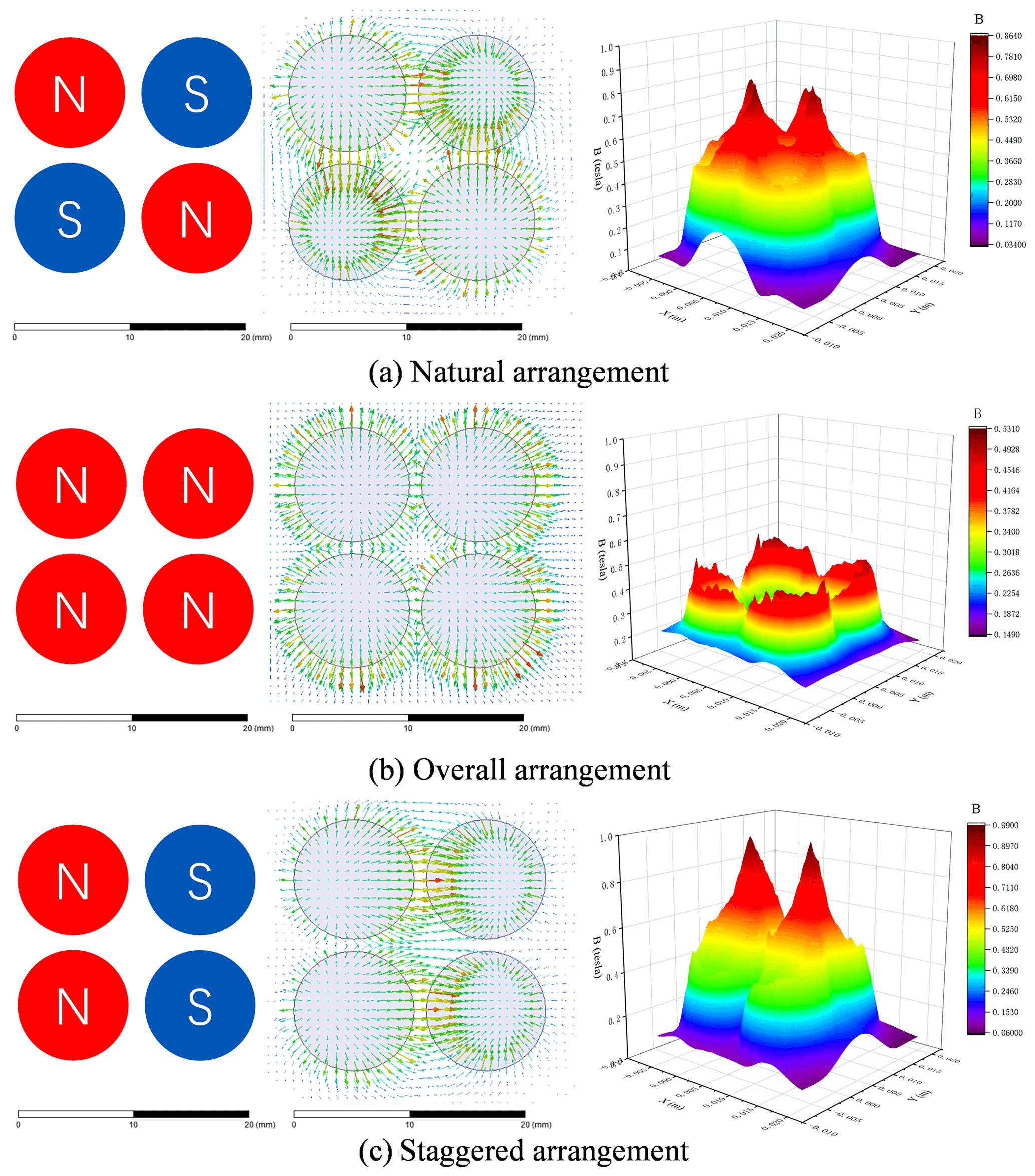
Figure 3Vector/scalar magnetic induction intensity cloud chart under the different arrangement of magnetic poles.
The distance between magnetic poles is 1.5 mm. The magnetic pole is simulated in four forms: natural arrangement, omnidirectional arrangement, and staggered arrangement. The vector magnetic induction intensity program and the scalar magnetic induction intensity program of the surface to be machined (working gap of 0.2 mm) can be obtained by simulation in Fig. 3.
As depicted in the vector cloud image in Fig. 3a, the naturally arranged magnetic field lines form a closed loop between the anisotropic magnetic poles. The magnetic field lines converge in the central region of the magnetic pole and are evenly distributed. In the edge region, the magnetic field lines extend and diverge to infinity, and the magnetic field lines are sparse in the region. The magnetic induction intensity cloud map of the surface to be processed (working gap of 0.2 mm) shows four peaks, and the maximum magnetic induction intensity is 0.863 T. Although a peak is present, the overall strength is relatively uniform, which is beneficial to the uniform adhesion of the polishing liquid to the surface to be processed. Figure 3b shows the vector cloud image, wherein the omnidirectional magnetic field line does not form a closed loop between homogeneous magnetic poles and the color of the central region is not uniform. In the edge region, the magnetic field line diverges and is densely arranged. The magnetic induction intensity cloud map of the surface to be processed (working gap of 0.2 mm) shows four “arc peaks” in the edge area, the maximum magnetic induction intensity is 0.531 T, and the magnetic induction intensity in the center is less than 0.3 T. Under this arrangement, the polishing liquid easily agglomerates in the edge area, which affects the uniformity of polishing. As depicted in the vector cloud image in Fig. 3c, the longitudinal staggered arrangement of magnetic field lines forms a closed loop between the anisotropic magnetic poles. The magnetic field lines converge in the central region of the magnetic pole and are evenly distributed. In the edge region, the magnetic field lines extend and diverge to infinity, and the magnetic field lines are sparse in this region. The magnetic induction intensity cloud map of the surface (working gap of 0.2 mm) shows two peaks, and the maximum magnetic induction intensity is 0.987 T, indicating reduced uniformity.
In summary, magnetic poles with natural arrangement are well arranged. Under this condition, the magnetic field distribution is uniform and the magnetic induction intensity is high.
3.1 Experimental device
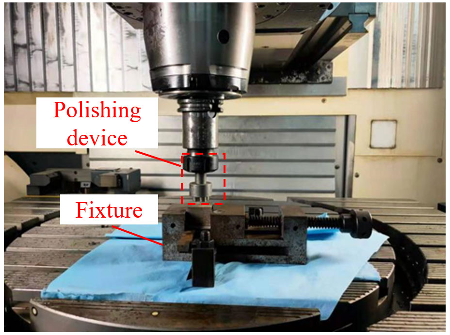
The polishing experimental device is depicted in Fig. 4, including polishing tools and sample fixtures. The polishing tool is mounted with an axially magnetized permanent magnet and installed on the spindle of the high-precision controlled three-axis linkage CNC machine tool, which can realize linear motion and rotational motion. The spindle rotation can drive the rotation of the permanent magnet, thereby driving the rotation of the polishing pad. The sample is clamped on the pliers, and the polishing pressure of the MRP pad on the polishing area is changed by adjusting the gap between the polishing tool and the sample.
3.2 316L stainless steel sample formed by L-PBF
In this study, 316L metal cube samples formed by L-PBF are used as polishing objects. Spherical 316L stainless steel powder (Beijing Yijia 3D Co., Ltd.) is used as the experimental material (Fig. 5). The composition is depicted in Table 1, and the particle size distribution is depicted in Table 2. The equipment adopts SLM-125 laser selective melting equipment (Fig. 5), the equipment adopts a single laser (1 × 400 W) IPG fiber laser, the maximum molding size is 125 mm × 125 mm × 125 mm, the maximum scanning speed is 10 m s−1, the layer thickness is 0.02–0.075 mm, and the molding room uses argon as protective gas. The forming process parameters are shown in Table 3.
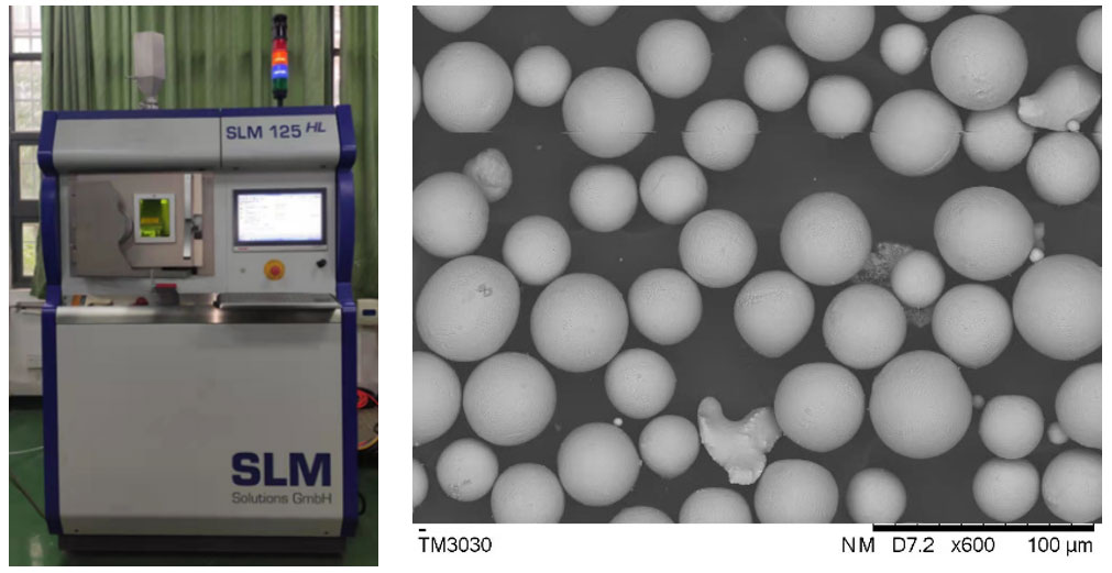

Table 2Particle size distribution and tap density of 316L stainless steel powder.
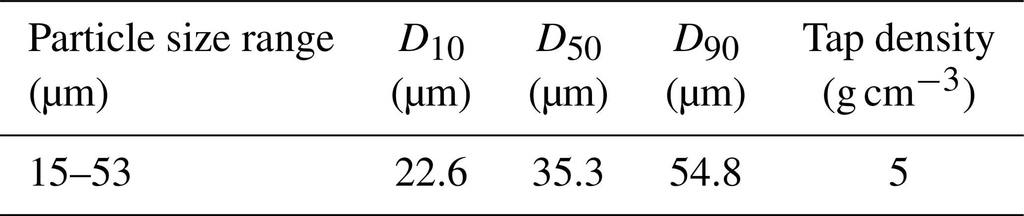
Table 3Selective laser melting process parameters of 316L stainless steel.
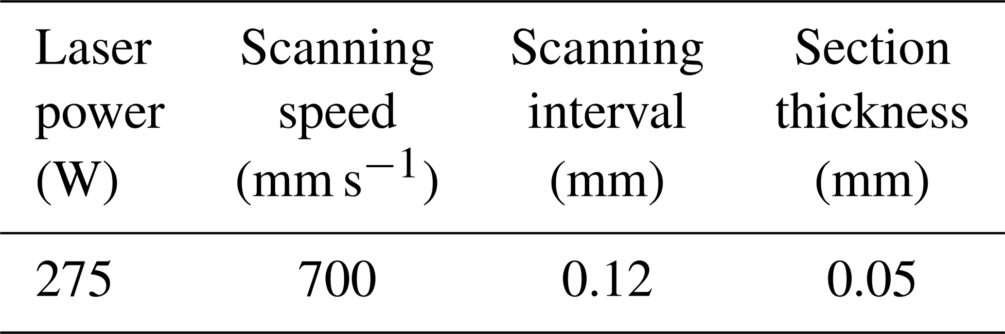
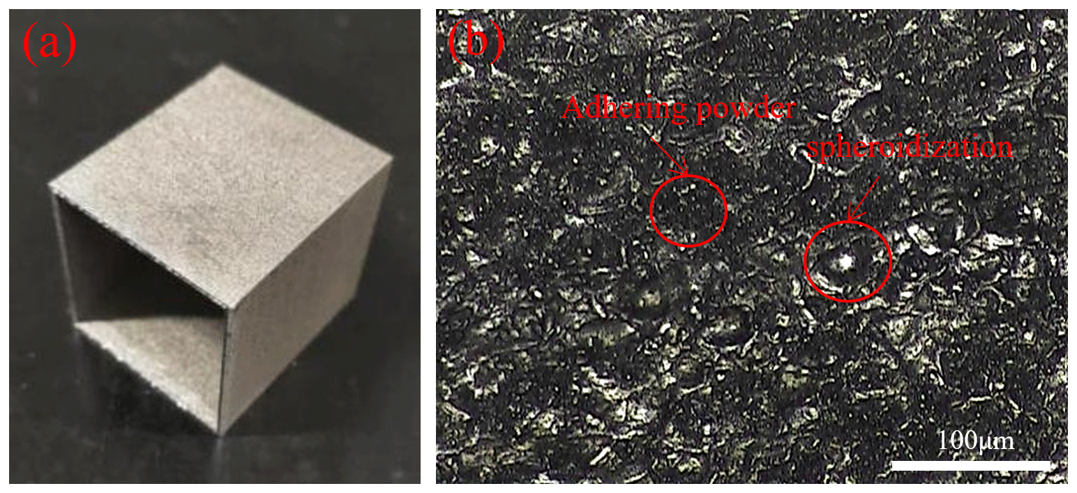
Figure 6a shows the polished sample of 316L stainless steel formed by L-PBF. The sample size is designed to be 30 mm × 30 mm × 35 mm hollow pentahedron, and the original surface roughness Ra is 5–15 µm. Figure 6b shows the surface micro-morphology of L-PBF-formed 316L stainless steel polishing sample. Adhesion and spheroidization of powder are evident on the surface, and argon is used as the protective gas in the molding chamber. Therefore, gas flow in the cabin drives the surrounding powder to cause the adhesion of the powder on the surface. Powder spheroidization occurs due to the molten liquid scattered on both sides of the molten pool after cooling and solidification. Spheroidization will lead to irregular shapes along the scanning trajectory, so the weld gap will occur repeatedly, thereby affecting the surface quality of the sample. Before the experiment, the sample is roughly cast to about 1.7 µm in the grinder.
3.3 Experiment parameters
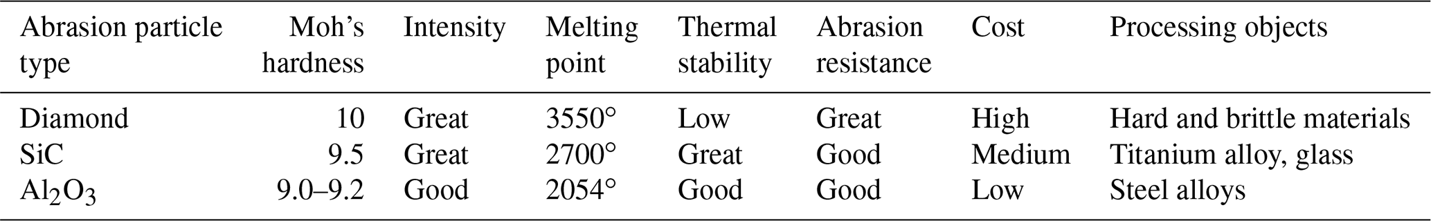
In the MRP process of the L-PBF-formed 316L stainless steel polishing sample, MRP fluid and process parameters are the main influencing factors. The primary variables affecting polishing quality and efficiency are abrasive particle size and hardness. Diamond, SiC, Al2O3, and other polishing materials are frequently utilized. Table 4 displays the abrasive particle performance. Al2O3 powder is chosen as the abrasive particle of the slurry for 316L stainless steel that SLM has manufactured. Al2O3 powder with a particle size of 3.0–4.0 µm is chosen to complement iron powder because carbonyl iron powder has a particle size of 3.0–4.0 µm (Nagdeve et al., 2018).
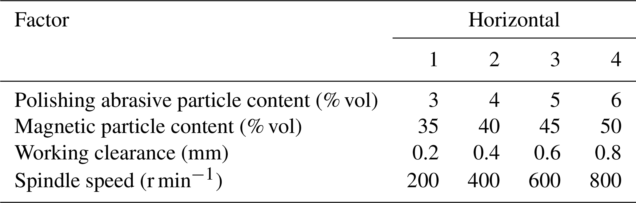
Four factors including polishing abrasive particle content, magnetic particle content, working gap, and spindle speed are selected to carry out single-factor experiments. The factor level data are depicted in Table 5. After polishing, the surface roughness of the sample was measured by Mahr-XR20 roughness meter, and the average value of three measurement points was taken as surface roughness Ra to evaluate the polishing effect. The surface morphology of the sample was observed by a white light interferometer.
4.1 Effect of Al2O3 abrasive content on surface roughness
During MRP, magnetic particles can clamp polishing abrasive particles to remove the material on the workpiece surface, and the content of polishing abrasive particles will affect the polishing effect to a certain extent. MRP fluid containing 3 % vol, 4 % vol, 5 % vol, and 6 % vol of brown corundum abrasive particles (namely, Al2O3) was selected for single-factor polishing experiments under the following conditions: polishing time of 30 min, working gap of 0.4 mm, spindle speed of 600 r min−1, and 45 % vol of iron powder in the polishing fluid. Figure 7 shows the influence of the polishing abrasive on the surface roughness and residual stress of the sample. With increasing content of the polishing abrasive, the surface roughness first decreases and then increases, and the maximum difference is 0.12 µm. When the polishing abrasive is 4 % vol, the surface roughness Ra of the sample reaches a low value of 0.18 µm. The residual stress increases from 41.16 to 71.2 MPa, and the overall broken line shows a slight upward trend, indicating that the increase in abrasive content had little effect on residual stress.
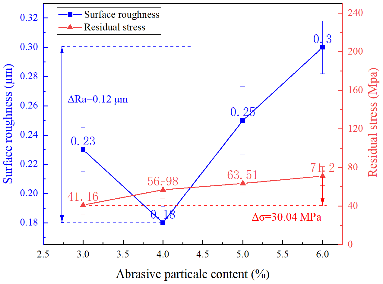
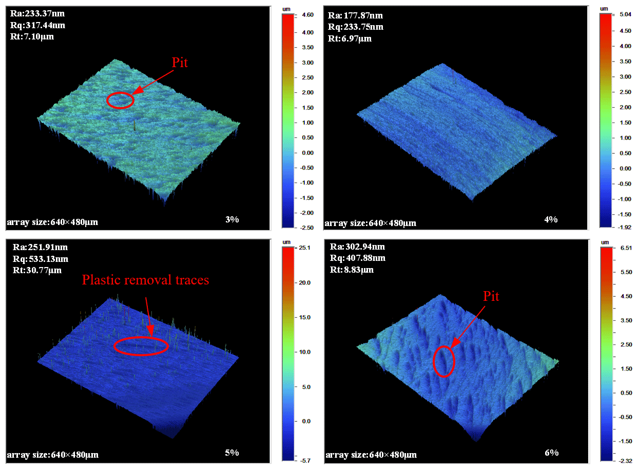
Figure 8 shows the polishing patterns of the workpiece observed by the white light interferometer under different polishing abrasive contents. When the content is 3 %, the number of abrasive particles involved in polishing is small, the magnetic particles can better constrain the polishing abrasive particles, and the surface roughness of the sample can reach 0.23 µm. However, the sample plot has many weld defects and obvious plastic removal traces because the polishing abrasive particles are less and the removal amount of the abrasive particles on the overall material is also less; as such, surface defects cannot be completely removed. When the contents are 5 % and 6 %, the surface processing quality is poor, and weld defects and obvious plastic removal traces are found on the surface of the sample. With increasing content of abrasive particles, the number of abrasive particles between magnetic particles increases, thereby affecting the formation of flux linkage and weakening the magneto-rheological effect. The abrasive particles involved in polishing are easy to escape the constraint, lacking the effect of only magnetic particles on the extrusion of the workpiece, and cannot effectively achieve the removal effect. The surface of the sample has many weld defects. When the abrasive content is 4 %, the surface quality is the best and the sample surface is flat and smooth with fewer defects.
4.2 Effect of magnetic particle content on surface roughness
The magnetic particles in MRP fluid are arranged into chains along the magnetic field line. The abrasive particles originally dissociated in the polishing fluid are clamped between magnetic particles and between flux linkage. The content of magnetic particles directly affects the formation of flux linkage, thereby affecting the polishing effect. MRP fluid containing 35 % vol, 40 % vol, 45 % vol, and 50 % vol hydroxyl iron powder was selected for single-factor polishing experiment under the following conditions: polishing time of 30 min, working gap of 0.4 mm, spindle speed of 600 r min−1, and 5 % vol polishing fluid. Figure 9 shows the changes in the surface roughness and residual stress of the sample with different hydroxyl iron powder contents. The surface roughness decreases first and then increases with increasing magnetic particle content, and the maximum difference is 0.12 µm. When the content is 40 %, the surface quality is good and the surface roughness reaches 0.13 µm. The residual stress increases from 68.72 to 91.71 MPa, showing a slight upward trend as a whole, indicating that the increase in the magnetic particle content had slight effect on residual stress.
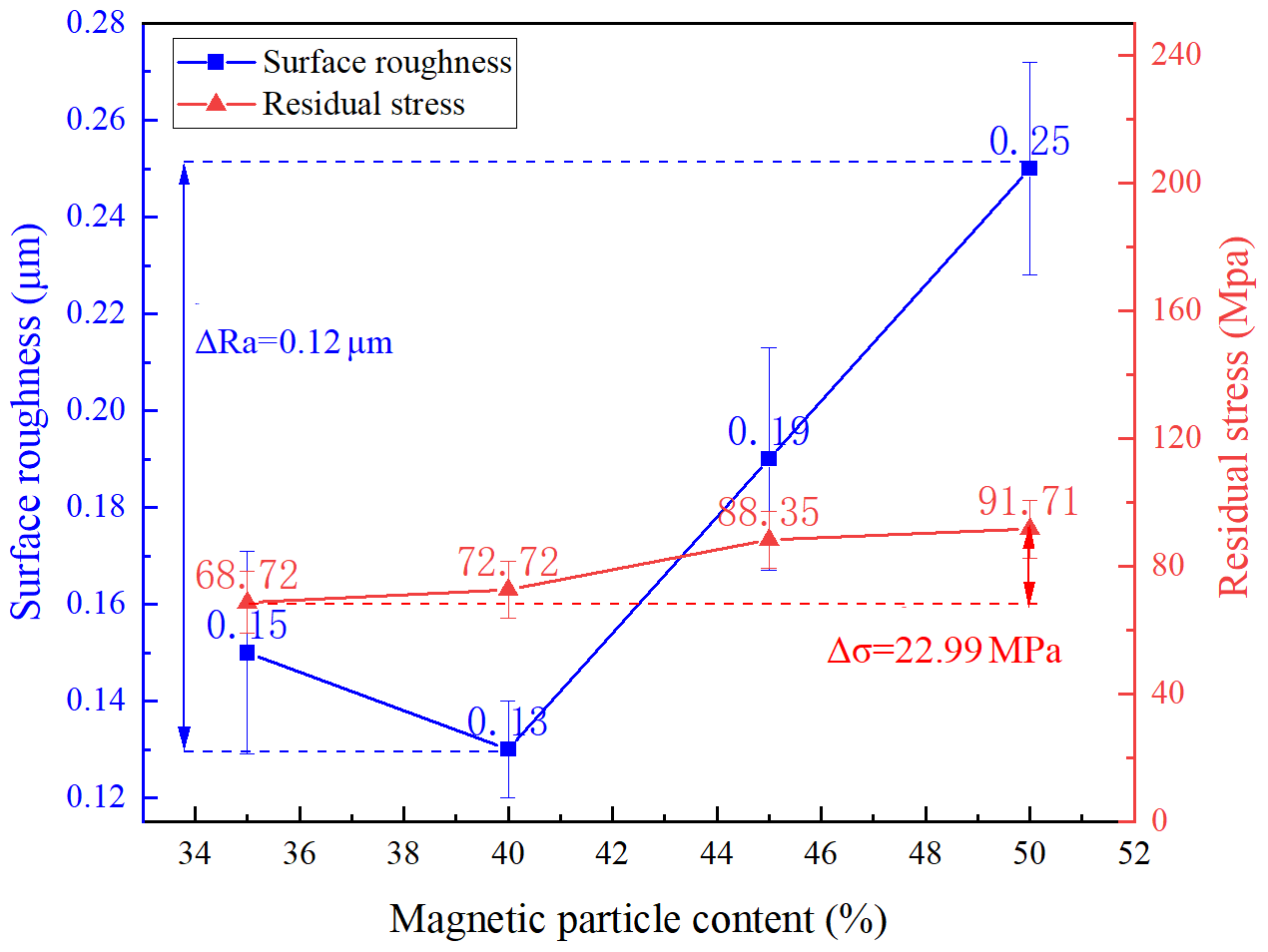
Figure 9Effect of different magnetic particle abrasive content on surface roughness of the sample.
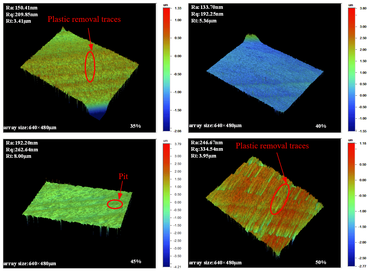
Figure 10 shows the polishing patterns of workpieces observed by a white light interferometer with different magnetic particle contents. When the content is 35 %, the sample has a small number of pits and plastic removal traces. The iron powder is less than the abrasive, and the clamping force provided by the iron powder is limited; as such, the abrasive cannot completely remove the surface defects. The surface quality is low, and the corresponding Ra value is 0.15 µm. When the content of iron powder is 40 %, the pits and removal traces are significantly reduced compared with that at 35 %. With increasing number of iron powder particles and the same content of abrasive particles, the number of iron powder and abrasive particles is close to the equilibrium. The clamping force provided by iron powder particles cannot only remove the surface defects of abrasive particles but also enable them to be timely separated to update the abrasive particles. Finally, the overall material removal is increased and the surface quality is improved. The optimal Ra value is 0.13 µm. When the contents are 45 % and 50 %, the surface of the sample has pits and removal marks. The amount of iron powder exceeds the number of abrasive particles due to the increase in the iron powder content, and the clamping force provided by iron powder particles is large. As such, the abrasive particles involved in polishing have difficulty to escape constraints, resulting in the difficulty of updating the passivated abrasive particles and affecting the quality of the final surface.
4.3 Effect of working gap on surface roughness
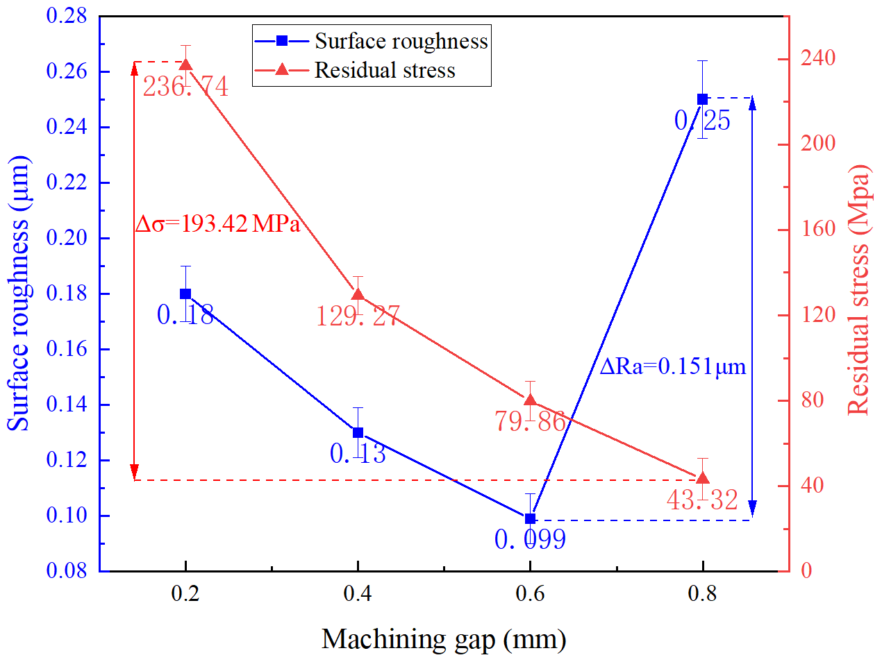
In different sizes of the working gap, the different thicknesses of the polishing pad formed by polishing liquid may affect the polishing force of the sample surface and the material removal rate and surface quality. The control experimental conditions are as follows: polishing time of 30 min, spindle speed of 600 r min−1, polishing liquid composition with iron powder concentration of 45 % vol, brown corundum concentration of 5 % vol under 0.2, 0.4, 0.6, and 0.8 mm processing conditions. Figure 11 shows the influence of working gap on the surface roughness and residual stress. With decreasing working gap, the surface roughness Ra first decreases and then increases, the maximum difference is 0.151 µm and reaches a small value at 0.6 mm ,and the surface roughness Ra is 0.099 µm. The residual stress decreases from 236.74 to 43.32 MPa with increasing working gap.
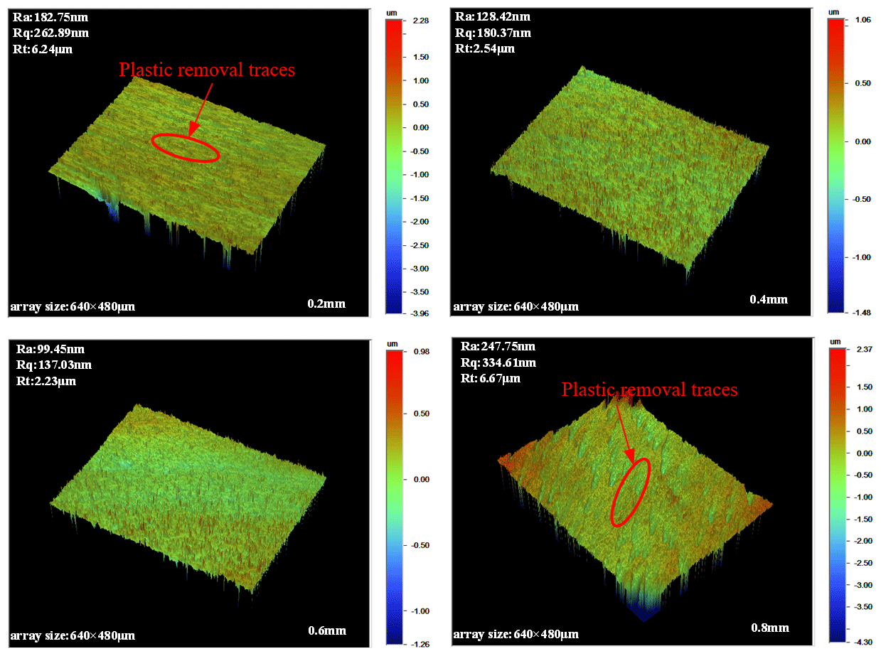
Figure 12 shows the surface topography of the workpiece observed by a white light interferometer under different working gaps. When the working gap is 0.2 mm, the surface of the sample has fewer residual pits and plastic removal traces during polishing. The polishing pad is thick, the magnetic field intensity is high, the binding force between the magnetic particles is strong, the position between the particles is relatively fixed, and the polishing force is large due to the small working gap. With larger binding force of the magnetic flux on the abrasive particles, the larger the polishing force is, the larger the residual stress is, and the surface roughness can reach 0.18 µm. However, due to the small working gap and the short magnetic flux, the abrasive particles are less, thereby affecting the removal effect. When the working gap is 0.6 mm, the working effect is better, the sample surface is smooth, and the pits are fewer; when the working gap is 0.8 mm, many unfinished meteoric plastic removal traces are found on the figure. The gap is too large and the magnetic field intensity is low; as such, the magnetic particle chain does not have sufficient clamping force on the abrasive particles. When the abrasive particles remove the material, the cutting force is greater than the clamping force, so the abrasive particles are separated from the clamping of the magnetic particles, thereby forming meteoric plastic removal traces.
4.4 Effect of spindle speed on surface roughness
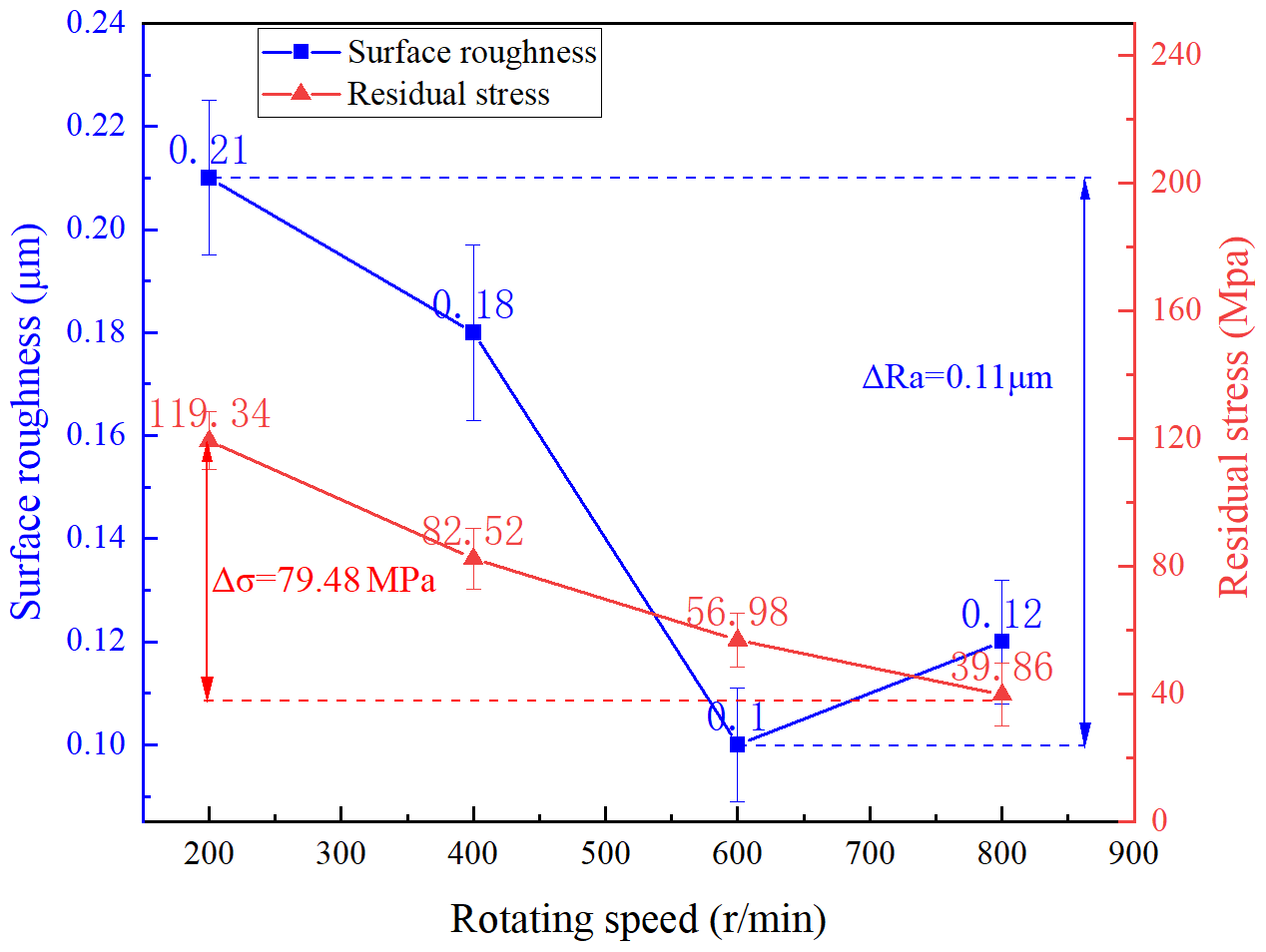
Spindle speed affects the relative linear velocity between the polished particle and the surface, thereby affecting the material removal of the sample surface by the MRP pad. The control experimental conditions are as follows: the working gap is 0.4 mm, the polishing time is 30 min, and the polishing liquid composition is 45 % vol of iron powder and 5 % vol of brown corundum. Figure 13 shows the influence of spindle speed on surface roughness and residual stress at different rotating speeds. With increasing spindle speed, the surface roughness Ra first decreases and then increases, and the maximum difference is 0.11 µm. When the spindle speed reaches 600 r min−1, the surface roughness is the lowest, reaching 0.10 µm. The residual stress decreases with increasing working gap from 119.34 to 39.89 MPa.
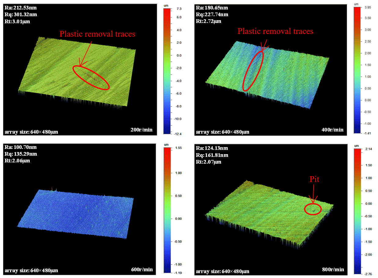
Figure 14 shows the surface topography of the workpiece observed by the white light interferometer at different spindle speeds. When the spindle speed is 200 r min−1, the micro-pattern has many defects and plastic removal traces and a visible channel direction. When the spindle speed is low, the polishing times of the workpiece are limited and the material removal amount is less in unit time; that is, the surface roughness is high. With increasing spindle speed, the material removal linear velocity and particle trajectory density of abrasive particles on the surface of the sample increase, thereby increasing the material removal rate and the surface quality of the sample increases and decreasing the surface roughness. When the speed reaches 600 r min−1, the surface roughness value is the lowest, reaching 0.10 µm. When the rotational speed exceeds 600 r min−1, the surface roughness increases. With the increase in the rotational speed of the spindle, the centrifugal force of the particles in the MRP pad increases, resulting in the deformation of the flux linkage, the decrease in the clamping force on the particles, and the escape of the particles from the magnetic chain. The particles are marginalized in the polishing area, the update speed of the particles in the flux linkage decreases and the material removal amount per unit time is less, thereby increasing the surface roughness.
4.5 Polishing experiment of optimizing process parameters
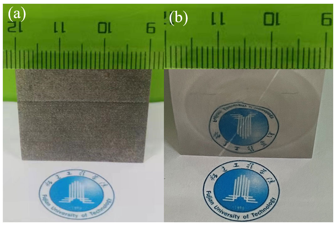
Based on the above experimental results of each process parameter, the optimized process parameters of L-PBF formation of 316L stainless steel are as follows: abrasive content of 4 %, magnetic particle content of 40 %, working gap of 0.6 mm, and spindle speed of 600 r min−1. The sample was polished for 30 min under the optimized parameters. The surface morphology of the workpiece observed by the white light interferometer of the 316L stainless steel sample formed by L-PBF is depicted in Fig. 15. The surface roughness Ra of the workpiece decreased from the initial 1.59 µm to 61.43 nm. The comparison before and after polishing is shown in Fig. 16, and the surface became smooth.
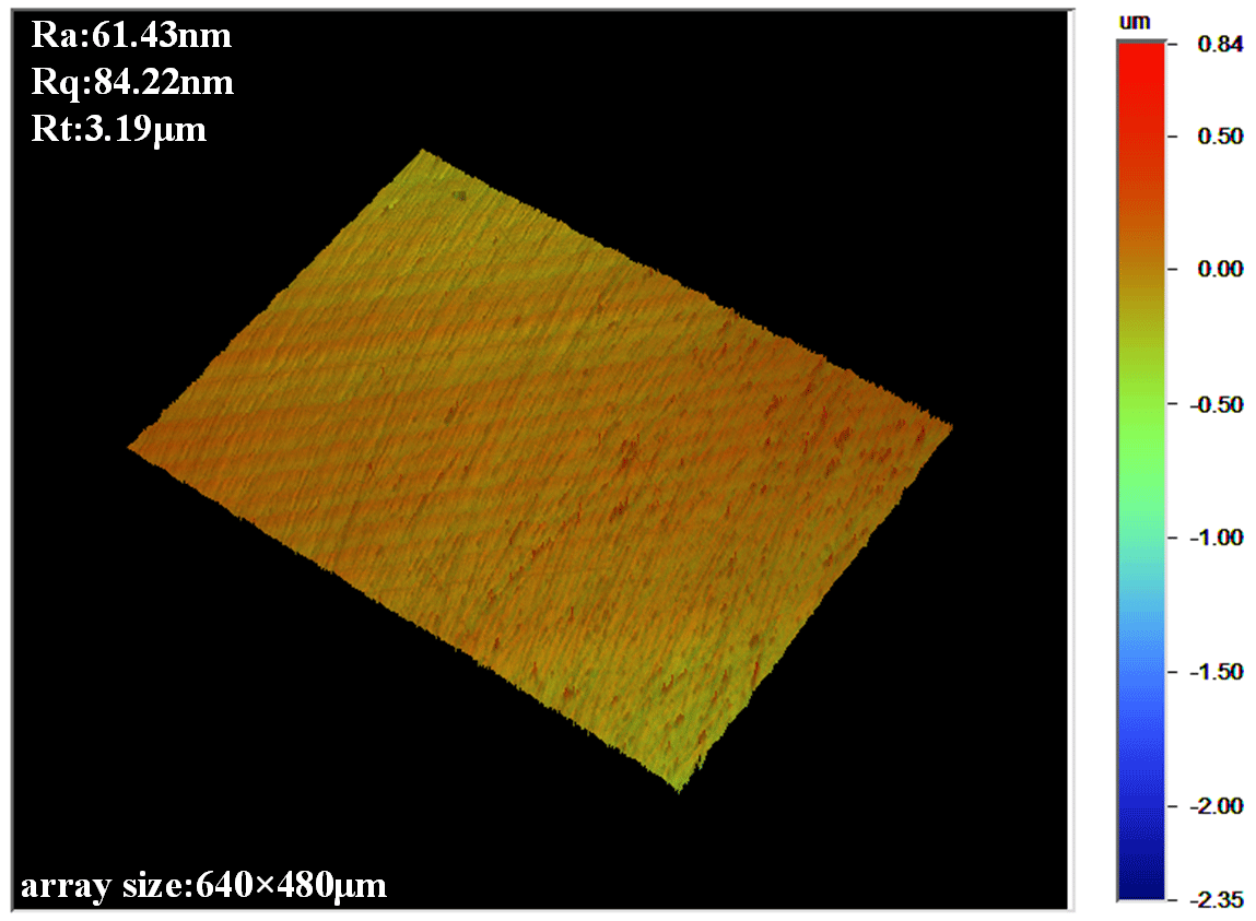
Figure 15Surface topography of 316L stainless steel sample under the optimum process parameters.
In this study, the surface post-processing of 316L stainless steel sample formed by L-PBF was carried out by MRP technology, and the polishing experimental device was set up. The influence and law of the main process parameters of MRP (abrasive content, magnetic particle content, working gap, polishing speed) on the surface roughness and residual stress of the sample were analyzed. The following conclusions were reached:
-
The content of abrasive particles and magnetic particles directly affects the number of abrasive particles involved in polishing and the polishing force provided by the polishing pad. With increasing content of abrasive particles and magnetic particles, the residual stress increases slightly and the surface roughness Ra decreases first and then increases. When the contents of abrasive particles and magnetic particles are 4 % and 40 %, respectively, the surface roughness Ra reaches the minimum.
-
The working gap affects the surface magnetic field strength and polishing pressure of the sample. With increasing working gap, the residual stress decreases and the surface roughness Ra decreases first and then increases. When the working gap is 0.6 mm, the surface roughness Ra is 99 nm.
-
Spindle speed affects the relative velocity of abrasive particles and sample surface and the morphology and distribution of abrasive particles of the MRP pad, thereby affecting the polishing effect. At larger spindle speed, the residual stress is small. The surface roughness Ra decreases first and then increases. When the spindle speed reaches 600 r min−1, the obtained surface roughness is low, reaching 100 nm.
-
The optimized process parameters for polishing are abrasive content of 4 %, magnetic particle content of 40 %, a working gap of 0.6 mm, and spindle speed of 600 r min−1. The surface roughness of the sample polished using the optimized parameters decreases from 1.59 µm to 61.43 nm.
The results can expand the application of MRP technology in the field of surface treatment of additive manufacturing parts, but limitations still exist, which would be the focus of future work. At present, MRP has low material removal efficiency. In the future, ultrasonic technology can be introduced to form ultrasonic magnetorheological composite polishing to determine the influence of ultrasonic frequency on material removal.
All data included in this study are available upon request by contacting the corresponding author.
NS, TG, and BC contributed significantly to the conception and design of work, data acquisition, analysis, and interpretation. ML and YX contributed to the acquisition of simulation experimental data and data collation. XP helped with the writing and language.
The contact author has declared that none of the authors has any competing interests.
Publisher's note: Copernicus Publications remains neutral with regard to jurisdictional claims in published maps and institutional affiliations.
This research has been supported by the Natural Science Foundation of Fujian Province (grant no. 2020J01874), the Program for Innovative Research Team in Science and Technology in Fujian Province University (2020 grant no. 12), Fujian Provincial Key Project of Science and Technology Innovation (grant no. 2022G02007), High-level Talents Foundation of Fuzhou Polytechnic (grant no. FZYRCQD 201903), and the National Natural Science Foundation (grant no. 52275413).
This paper was edited by Jeong Hoon Ko and reviewed by two anonymous referees.
Aboulkhair, N. T., Simonelli, M., Parry, L., Ashcroft, I., and Hague, R.: 3D printing of aluminium alloys: additive manufacturing of aluminium alloys using selective laser melting, Prog. Mater. Sci., 106, 100578, https://doi.org/10.1016/j.pmatsci.2019.100578, 2019.
Ashtiani, M., Hashemabadi, S. H., and Ghaffari, A.: A review on the magnetorheological fluid preparation and stabilization, J. Magn. Magn. Mater, 374, 716–730, https://doi.org/10.1016/j.jmmm.2014.09.020, 2015.
Atabay, S. E., Sanchez-Mata, O., Muniz-Lerma, J. A., Gauvin, R., and Brochu, M.: Microstructure and mechanical properties of rene 41 alloy manufactured by laser powder bed fusion, Mater. Sci. Eng., 773, 138849, https://doi.org/10.1016/j.msea.2019.138849, 2020.
Bagehorn, S., Wehr, J., and Maier, H. J.: Application of mechanical surface finishing processes for roughness reduction and fatigue improvement of additively manufactured Ti-6Al-4V parts, Int. J. Fatigue, 102, 135–142, https://doi.org/10.1016/j.ijfatigue.2017.05.008, 2017.
Barman, A. and Das, M.: Nano-finishing of bio-titanium alloy to generate different surface morphologies by changing magnetorheological polishing fluid compositions, Precis. Eng, 51, 145–152, https://doi.org/10.1016/j.precisioneng.2017.08.003, 2018.
Bezuidenhout, M., Haar, G. T., Becker, T., Rudolph, S., and Sacks, N.: The effect of hf-hno3 chemical polishing on the surface roughness and fatigue life of laser powder bed fusion produced ti6al4v, Mater. Today., 25, 101396, https://doi.org/10.1016/j.mtcomm.2020.101396, 2020.
Chen, B., She, N., Lin, D., Yan, X., and Peng, X. Q.: Experimental study on the nonlinear vibration of a new composite magnetorheological damping system, Mech. Syst. Signal Pr., 181, 109480, https://doi.org/10.1016/j.ymssp.2022.109480, 2022.
Chen, L., Richter, B., Zhang, X., Bertsch, K. B., Thoma, D., and Pfefferkorn, F. E.: Effect of laser polishing on the microstructure and mechanical properties of stainless steel 316l fabricated by laser powder bed fusion, Mater. Sci. Eng. A, 802, 140579, https://doi.org/10.1016/j.msea.2020.140579, 2021.
Chlebus, E., Kuźnicka, B., Kurzynowski, T., and Dybała, B.: Microstructure and mechanical behaviour of Ti-6Al-7Nb alloy produced by selective laser melting, Mater. Charact., 62, 488–495, https://doi.org/10.1016/j.matchar.2011.03.006, 2011.
Ghosh, G., Sidpara, A., and Bandyopadhyay, P. P.: Experimental and theoretical investigation into surface roughness and residual stress in magnetorheological finishing of OFHC copper, J. Mater. Process. Tech., 288, 116899, https://doi.org/10.1016/j.jmatprotec.2020.116899, 2021.
Herzog, D., Seyda, V., Wycisk, E. M., and Emmelmann, C.: Additive Manufacturing of Metals, Acta Mater., 117, 371–392, https://doi.org/10.1016/j.actamat.2016.07.019, 2016.
Li, M., Lyu, B., Yuan, J. L., Yao, W., Fenfen, Z., and Meipeng, Z.: Evolution and equivalent control law of surface roughness in shear-thickening polishing, Int. J. Mach. Tool Manu., 108, 113–126, https://doi.org/10.1016/j.ijmachtools.2016.06.007, 2016.
Li, N., Huang, S., Zhang, G., Qin, R., Liu, W., Xiong, H., Shi, G., and Blackburn, J.: Progress in additive manufacturing on new materials: A review, J. Mater. Sci. Technol., 35, 242–269, https://doi.org/10.1016/j.jmst.2018.09.002, 2019.
Lodhi, M., Deen, K. M., Greenlee-Wacker, M. C., and Haider, W. M.: Additively manufactured 316L stainless steel with improved corrosion resistance and biological response for biomedical applications, Additive Manufacturing, 27, 8–19, https://doi.org/10.1016/j.addma.2019.02.005,2019.
Malaga, A. K., Agrawal, R., and Wankhede, V. A.: Material selection for metal additive manufacturing process, Mater. Today-Proc., 66, 1744–1749, https://doi.org/10.1016/j.matpr.2022.05.272, 2022.
Mariani, F. E., Ribeiro, K. S. B., Lombardi, A. N., Casteletti, L. C., and Coelho, R. T.: Effect of Laser Polishing Post-Processing Technique on the Roughness and Wear Resistance of Inconel 625 Deposited by Laser Cladding on AISI 304L Stainless Steel, J. Mater. Eng. Perform., 30, 6713–6721, https://doi.org/10.1007/s11665-021-05962-3, 2021.
Nafar Dastgerdi, J., Jaberi, O., and Remes, H.: Influence of internal and surface defects on the fatigue performance of additively manufactured stainless steel 316L, Int. J. Fatigue., 163, 107025, https://doi.org/10.1016/j.ijfatigue.2022.107025, 2022.
Nagdeve, L., Sidpara, A. M., Jain, V. K., and Ramkumar, J.: On the effect of relative size of magnetic particles and abrasive particles in MR fluid-based finishing process, Mach. Sci. Technol., 22, 493–506, https://doi.org/10.1080/10910344.2017.1365899, 2018.
Neda, M., Sylvain, T., and Vladimir, B.: Surface finish control of additively-manufactured Inconel 625 components using combined chemical-abrasive flow polishing, J. Mater. Process. Tech., 252, 728–738, https://doi.org/10.1016/j.jmatprotec.2017.10.020, 2017.
Roland, T., Retraint, D., Lu, K., and Lu, J.: Fatigue life improvement through surface nanostructuring of stainless steel by means of surface mechanical attrition treatment, Scripta. Mater., 54, 1949–1954, https://doi.org/10.1016/j.scriptamat.2006.01.049, 2006.
Sanaei, N. and Fatemi, A.: Analysis of the effect of internal defects on fatigue performance of additive manufactured metals, Mater. Sci. Eng. A, 785, 139385, https://doi.org/10.1016/j.msea.2020.139385, 2020.
Sidpara, A., Das, M., and Jain, V. K.: Rheological Characterization of Magnetorheological Finishing Fluid, Mater. Manuf. Process., 24, 1467–1478, https://doi.org/10.1080/10426910903367410, 2009.
Souza, A. M., Ferreira, R., Barragán, G., Nuñez, J. G., Mariani, F. E., Silva, E. J., and Coelho, R. T.: Effects of laser polishing on surface characteristics and wettability of directed energy-deposited 316L stainless steel, J. Mater. Eng. Perform., 30, 6752–6765, https://doi.org/10.1007/s11665-021-05991-y, 2021.
Wan, S., Wei, C., Hu, C., Situ, G., Shao, Y., and Shao, J.: Novel magic angle-step state and mechanism for restraining the path ripple of magnetorheological finishing, Int. J. Mach. Tool Manu., 161, 103673, https://doi.org/10.1016/j.ijmachtools.2020.103673, 2021.
Xu, Z., Wang, J., Yin, S., Wu, H., and Yi, L.: Compound Machining of Tungsten Alloy Aspheric Mould by Oblique-axis Grinding and Magnetorheological Polishing, Int. J. Precis. Eng. Man., 22, 1487–1496, https://doi.org/10.1007/s12541-021-00504-2, 2021.
Yadav, R. D. and Singh, A. K.: A novel magnetorheological gear profile finishing with high shape accuracy, Int. J Mach. Tool. Manu., 139, 75–92, https://doi.org/10.1016/j.ijmachtools.2019.02.001, 2019.
Yadroitsev, I., Bertrand, P., and Smurov, I.: Parametric analysis of the selective laser melting process, Appl. Surf. Sci., 253, 8064–8069, https://doi.org/10.1016/j.apsusc.2007.02.088, 2007.