the Creative Commons Attribution 4.0 License.
the Creative Commons Attribution 4.0 License.
 | 23 Mar 2023
Composite synchronization of three inductor motors with a circular distribution by a fuzzy proportional–integral–derivative method in a vibration system
Lei Jia
Jiankang Yang
Xiaojiao Gu
Ziliang Liu
Xiaoying Ma
In this article, the composite synchronization of three inductor motors with a circular distribution by a fuzzy PID (proportional–integral–derivative) method in a vibration system is investigated. The composite synchronization motion is comprised of self-synchronization and controlled synchronization motions. In the self-synchronization section, the electromechanical coupling dynamical model of the vibration system is established by introducing an inductor motor model into the dynamic model. The responses of the vibrating system are calculated, and the synchronous condition and stability criterion are both derived. With the controlled synchronization section, a master–slave controlling strategy and fuzzy PID method are applied on the controlling model. The stability of the control system is proved by the Lyapunov stability theory. A series of simulations are employed to demonstrate the practicability of the designed method. Finally, some experiments are conducted to verify the effectiveness of the proposed control method in practical application. The proposed control method exhibits a superior ability to satisfy the control of multiple motors, to be accurate in targeting the rotational speed arrival, and to be strongly robust against uncertainties and disturbances. The composite synchronization theory introduces a novel concept to design and develop types of vibration equipment.
- Article
(5218 KB) - Full-text XML
- BibTeX
- EndNote


Machines play a very important role in the development of industrial processes, but the performance of many machines cannot keep up with the development of the industry. To solve this problem, various machines have been manufactured, and the vibratory machine is one of them. Because of the diversity of functions, vibratory machines have an irreplaceable place in various fields. For example, the ground of construction foundations, machine finishing, and soil manipulation processes (Goanţă et al., 2022; Hashimoto and Johnson, 2015; Rao et al., 2018). The vibration machine is different from traditional machines which rely on rigid or flexible connections to complete the work. Most vibrating machines can realize linear motions or swing motions when driven by a shaft transmission. The key to achieving the above two motions is controlling the rotation of the shaft. The technology of the shaft transmission is used in many machines, such as chair systems and electric vehicles (Wei et al., 2022; Liu et al., 2017), even though the field of application of shaft transmission technology is so vast. The introduction of a control method for vibration equipment to achieve an ideal motion is an extremely complicated problem. The synchronization of the shaft is one of the problems solved by the control method. Synchronization is a special physical phenomenon, which means that shafts have the same physical characteristics of motion, such as speed or acceleration, because the synchronization phenomenon has been extensively researched by many engineering experts. The theory of synchronization has been widely studied and summarized in engineering. Czolczynski et al. (2012) studied the synchronization of pendulums and discovered transient synchronization among different pendulums. Machines with a multi-shaft synchronous motion are the future development direction of vibration machines; these machines are simpler, cheaper, and have a lower power consumption. However, these kinds of machines and equipment have many shortcomings that need to be remedied. For example, the working efficiency utilization rate of vibrating machines cannot meet engineering requirements. To address this drawback, the rotational speed and phase difference in the shaft need to be controlled. To solve the problem of insufficient power of vibration machines, the number of shafts can be increased to respond to this phenomenon. However, the volume of vibration machines will be increased in this way, which will lead to the installation of vibration machines requiring more space. Blekhman et al. (1997) explored and contrasted the traits of controlled synchronization and self-synchronization, respectively. A vibration machine equipped with a control method is suitable for more working conditions, which eliminate the above disadvantages of vibration machines. The problem of composited synchronization will be investigated in this paper.
The appearance of synchronization is quite frequent. The synchronization phenomenon is not only an external manifestation but also actually caused by the internal physical characteristics of objects. Synchronization has experienced a long development in the field of engineering. Many researchers have launched a series of research on the self-synchronization of multi-ERs (eccentric rotors) in various vibrating systems, and many achievements have been made. Zhao et al. (2010, 2011a, b) transformed the problem of synchronization in engineering into a solution of the equation in the field of mathematics by discussing the characteristics of the coupling dynamics among motors and the influence of parametric variation on the vibrating system in detail. Zhang et al. (2012, 2013a, b, 2014) investigated the synchronization theory of differently deployed ERs and supported their studies by experiments. From the above research, the foundation of the self-synchronization theory has been laid. Zhang et al. (2019) studied the behavior of two synchronous ERs with different excitation forces. The vibration system can provide a new form of synchronization by turning off the power of one motor. Jia et al. (2022) analyzed the self-synchronization of four circular symmetrical motors, which provides theoretical guidance for circular vibration equipment. Zhang et al. (2017) investigated the self-synchronization between two ERs and a cylindrical roller, opening up a new way of applying vibration machines. Gu et al. (2018, 2019, 2022) extended the synchronization theory to one motor and two cylindrical rollers, with two motors and two cylindrical rollers distributed horizontally, and one motor with three cylindrical rollers distributed circumferentially in a vibration system.
With the development of control technology, controlling the position, speed, and error in the shaft is no longer a rare phenomenon, which greatly improves the working environment of vibration machines. For instance, Chen and Chen (2012) employed a H∞ control method to generate a position command, which has an exact motion control for axles. The command formation simplifies the control process. Barambones and Alkorta (2014) developed a controller to provide accurate position control for induction motor applications, while minimizing the performance impact of system uncertainties. Sun (2003) introduced cross-coupling technology into the accommodative control structure, providing a new control method to reduce the error in the shaft transmission and the error in the shaft position. Li et al. (2016) proposed a mean deviation coupling method. This method solves the problem of complex control structure of motors. Chen et al. (2018) improved the self-adjusting cross-coupling control structure, reducing the error in the start-up process and shortening the start-up time of motors. Jia et al. (2023) introduced the fuzzy PID (proportional–integral–derivative) method into the vibration system to study the multi-frequency control synchronization of four motors. The adaptive-sliding-mode control (ASMC) method was introduced to the vibration system to investigate the question of the composited synchronization of three ERs distributed horizontally and four ERs distributed symmetrically (Kong et al., 2018; Kong and Wen, 2018).
The incorporation of control methods into vibration systems to control the phase difference is less involved in the studies mentioned above. The organization of the present article is as follows. In Sect. 2, the mathematical model of vibration system is established by combining the Lagrange equation. In Sect. 3, the synchronization condition and stability condition of control synchronization are analyzed. In Sect. 4, the control method is designed, and the stability of the control method is discussed. In Sect. 5, a series of experiments and simulations are carried out to further verify the correctness of the theory. In Sect. 6, some conclusions are drawn.
Figure 1 shows the model of three ERs in a vibration system and three ERs driven by three induction motors separately.
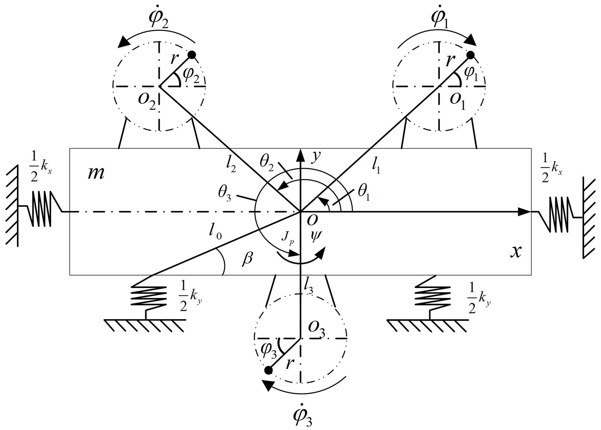
Three motors are fixed on the rigid frame, and the rigid frame is supported by four springs, which supply the stiffness and damping of the vibration system. Motor 1 and motor 2 are distributed on both sides of the rigid body symmetrically, and motor 3 is installed at the centerline below the rigid body. Motor 1 and motor 3 rotate clockwise. Motor 2 rotates counterclockwise. x, y, ψ, φ1, φ2, and φ3 are selected as the generalized coordinate of the vibration system. Setting the counterclockwise rotation as the positive direction and combining it with Lagrange equations, the motion differential equations of the vibration system are expressed as follows (Kong et al., 2018):
with
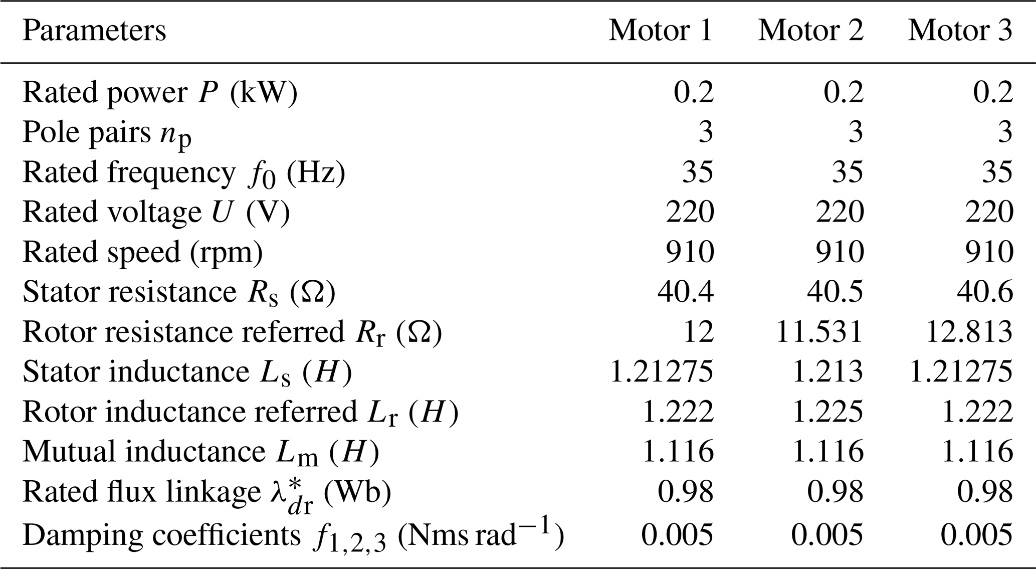
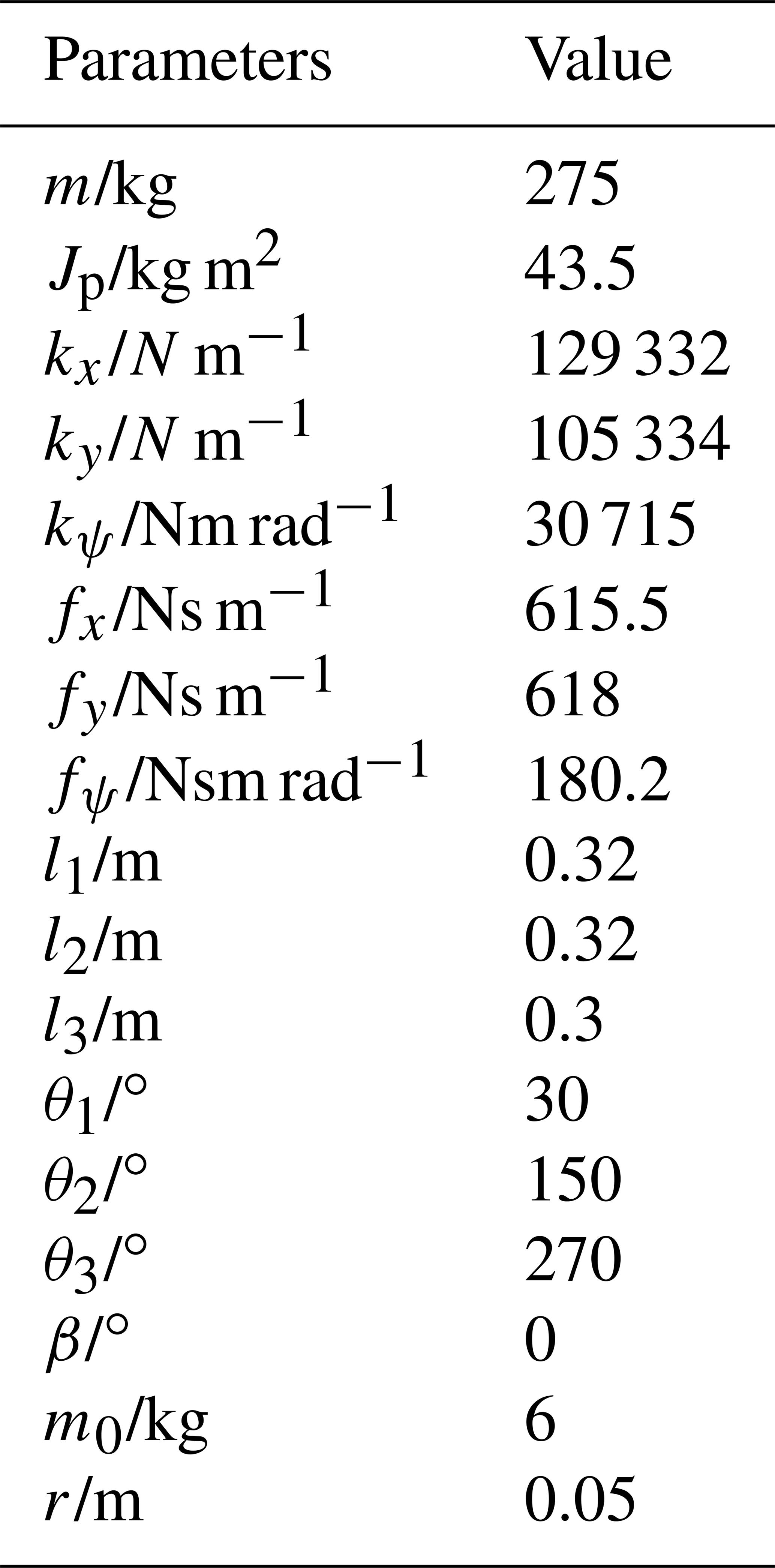
where the installation center of the rigid frame is indicated by o, and o1, o2, and o3 represent the rotation shaft centers of the three motors, respectively. The distance between ERs and rotating shaft of motors is rotation radius of the ERs expressed by r. θ1, θ2, and θ3 represent the angle between the rotation center of the three ERs and the x direction, respectively, where ∘, and θ3 = 270∘. kx, ky, kψ and fx, fy, fψ represent the stiffness and damping coefficients provided by the vibration system in the x, y, and ψ directions, where . The quality of three ERs is represented by m1, m2 and m3. m0 is the quality of the spring rigid body, and M is the total quality of all objects, . J1, J2 and J3 represent the moment of inertia of three ERs, respectively, where J1≈m1r2, J2≈m2r2, J3≈m3r2, J4≈m4r2. J is the total moment of inertia of the vibration system, where . Jb is the moment of inertia of the spring rigid. le is the equivalent rotation radius of the system. Te1, Te2 and Te3 are the electromagnetic torques of three induction motors. TL1, TL2, and TL3 represent the load torques on three induction motors. The parameters of three motors and vibration system and the nomenclature of the symbols are shown in Tables 1 and 2 and Appendix C, respectively.
Three induction motors provide electromagnetic torques for ERs, respectively. To clarify the motion mechanism of the vibration system, the state expression of induction motors can be deduced as follows:
In the electric machine theory, the d and q axes, respectively, are represented by the subscripts d and q. The flux linkage consists of φdr and φqr. Because of the features of the inductor motor, its inner structure is a short circuit, so φdr is a constant, and ϕqr=0. ids and iqs represent the stator current. uds and uqs are the stator voltage. Rs and Rr are the resistance of stator and rotor. Ls and Lr are the self-inductance coefficient of the stator and rotor. Lm is the mutual inductance coefficient, and Tr is the rotor time constant, where . σ indicates the leakage coefficient, where . np is the number of pole pairs of the induction motor. ωe represent the synchronous angular velocity. ω is the mechanical angular velocity.
According to the state equation of the induction motor, the electromagnetic torque of each motor is obtained as follows:
where .
In this section, the scheme and theory of control synchronization of the vibration system are discussed. Figure 2 shows the control synchronization scheme, which shows the method used in each step of applying the control synchronization.
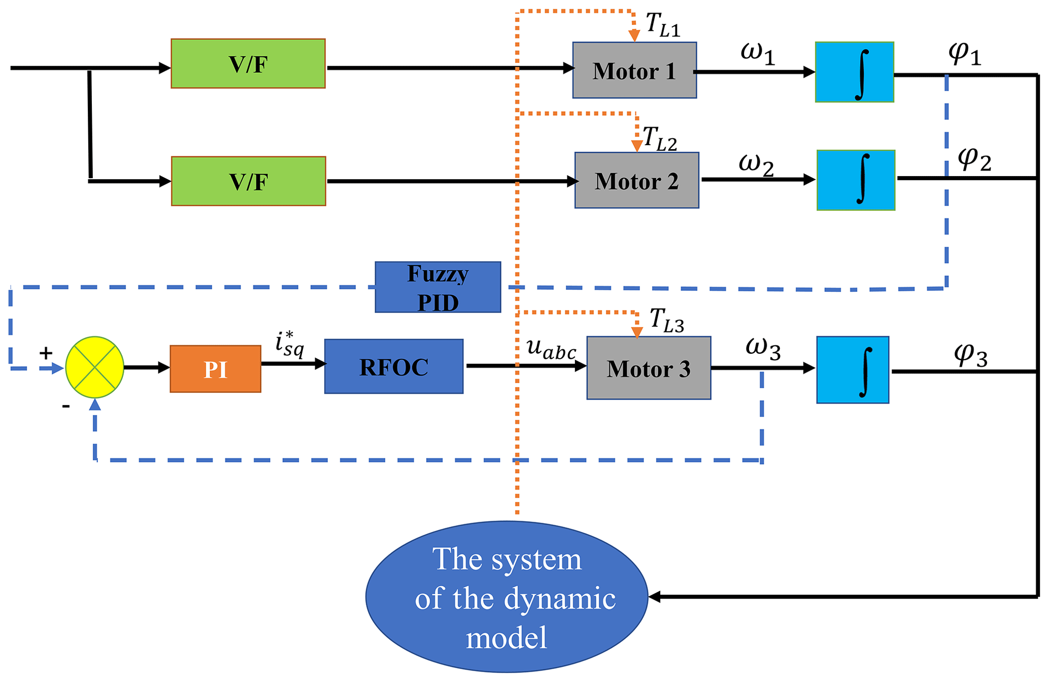
The control synchronization is based on self-synchronization, and the control part adopts a master–slave control scheme. Motor 1 is the master motor, with motor 2 implementing a self-synchronization motion by using the voltage/frequency (V/F) open-loop control algorithm with the same input frequencies. Therefore, ER 1 and ER 2 can rotate with same frequencies. Motor 3, as the slave motor, follows motor 1 by using the control method so that motor 1 and motor 3 can achieve a control synchronization with a zero-phase difference. As mentioned above, the composite synchronization of the three ERs is finally realized.
Under the action of the control method, φ1=φ3.
If ERs 1 and 2 are in a condition of self-synchronization, then the average phase and phase difference in the two ERs are φ and 2α, respectively. The phase of the two ERs can be represented as follows:
When three ERs reach the synchronous state, then the rotation speeds of the ERs are equal, namely
where T0 represents a single cycle of the motion system.
By introducing the time-varying coefficients ε1 and ε2, the rotation speed of two ERs can be described as follows:
Equation (7) expresses the angular accelerations of ERs 1 and 2 as follows:
When the system is in a synchronous state, then , so . and can be obtained. Ignoring the higher-order trace of the system, the responses of the system in different directions can be derived as follows:
where , , , , , , , , , , , , , , .
Integrating in the least common period from 0 to 2π with the variable of φ, the last equation of Eq. (1) can be expressed as follows:
with
where aij, bij, and κi (i, j=1, and 2) are listed in Appendix A.
The electromagnetic torques and load torques of the induction motors are applied to Eq. (9). Thus, Eq. (11) can be obtained.
where
, , . , , and νi (i=1, 2, 3 and j=1, 2, 3) are listed in the Appendix B.
3.1 Synchronization condition
When the vibrating system realizes the stable synchronization motion, then and are obtained. When combined with Eq. (11), the condition of two ERs realizing self-synchronization can be deduced as ν=0, which can be expressed as follows:
TeN1 and TeN2 represent the rated electromagnetic torques of motor 1 and motor 2, respectively.
3.2 Stability condition
When two ERs are in the state of self-synchronization, then we can work out the average angular velocity ω0 and the average phase difference 2α0 from Eq. (12). By combining it with Eq. (11), Eq. (13) can be obtained as follows:
It is easy to find det(A)≠0, so Eq. (13) can be rewritten as follows:
with .
From , the characteristic equation of Eq. (14) is deduced as follows:
where λ represents the eigenvalues. are the coefficients of Eq. (15). In order to realize the stability of vibration system, all real parts of λ should be negative; if not, the stability of vibration system is impossible to achieve. According to the Hurwitz theory, the premise of stability can also be expressed as follows:
The master–slave control strategy was selected for its reliability and validity. Motor 1 is the master motor, and motor 3 is the slave motor. Fuzzy PID and rotor-flux-oriented control (RFOC) are added to the vibration system to implement the control synchronization between motors 1 and 3. ωt is the target speed of motor 1, so the speed of motor 1 can be obtained. ω1 is divided into two channels. The first is the target speed of motor 2, and the other is transmitted to the dynamic coupling model of the vibration system. The scheme of RFOC is illustrated in Fig. 3.
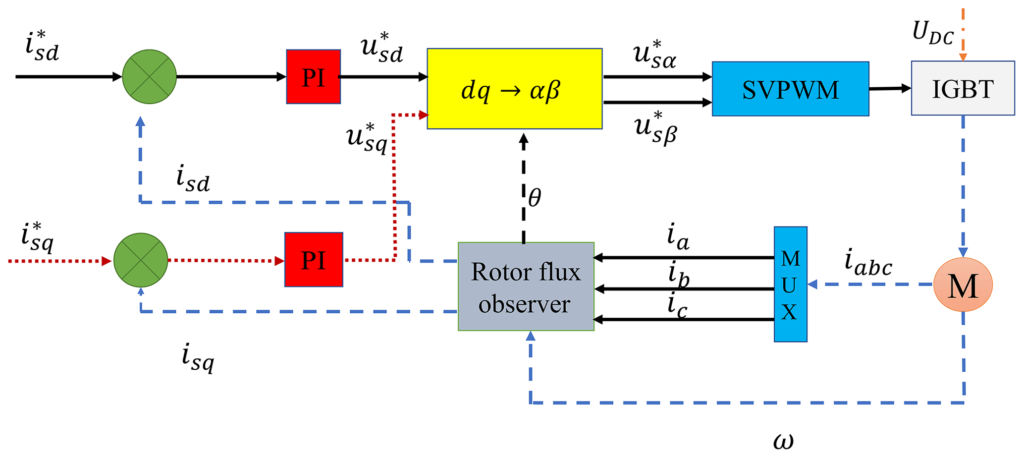
When the PID parameters are not chosen, then the fuzzy PID approach is extremely beneficial because the fuzzy PID approach can adjust the parameters adaptively according to the state of the vibration system. The control system adopts two input and three output values; two input values are the systematic error (e) and the rate of error change (ec). Three output values are kp, ki, and kd. When the values of kp, ki, and kd are chosen, then the vibration system is controlled successfully.
4.1 The stability analysis of the fuzzy PID method
Realizing the same speed of the motors is the premise of the control part. The speed of the motors should be one of the control targets. First, the speed of the induction motor is selected as the state variable. Setting , Eq. (1) can be rewritten as follows:
where , , , u1 represents , u2 represents , and u3 represents , , , and . The speed error can be obtained by the difference between the real-time rotational speed (ω) and the given speed (ωt).
Subsequently, the tracking error in the motors can be expressed as . It is not absolutely accurate to control the rotation speed with the control method. From Eqs. (17) and (18), the control rate can be expressed as follows:
where , , so the accommodative rate of the system can be set as
P is a positive definite matrix to ensure that the weight coefficient θf is bounded and the optimal weight coefficient is the subset of the convex set Ωf. Thus, can be deduced as follows:
By applying Eq. (19) to Eq. (17), the dynamic expression of the system can be expressed as follows:
where
By substituting Eqs. (18) and (19) into Eq. (20), the approximate error equation of the system can be expressed as follows:
where .
To obtain the minimum result of E and , the Lyapunov function can be expressed as follows:
where ζ is a positive number. P is a positive definite matrix and is suitable for the criterion of the Lyapunov equation.
Setting , , so , and . According to , is obtained. Then, we need to find out the appropriate values of Γ, which can make the value of within .
4.2 The stability analysis of the control system
φ1 is the target phase of motor 3; therefore, the phase difference between motor 1 and motor 3 can be expressed as follows:
Applying the method mentioned above, the stability of the phase difference between motor 1 and motor 3 can be proved.
5.1 Simulation results of composite synchronization
In order to guarantee the practicability of the control method, a series of simulation studies are carried out on composite synchronization through MATLAB/Simulink. The self-synchronization part includes motor 1 and motor 2, and the control synchronization part includes motor 1 and motor 3. The initial speed of the three motors is 0, and their frequencies are all set as 35 Hz. The simulation time is 40 s. At the beginning, the control synchronization motion is unsuccessfully implemented without the proposed control method. Based on this result, the control synchronization simulation is carried out by introducing the fuzzy PID control method into the vibration system, and the simulation results are obtained based on = 0.5, l1=l2 = 0.32 m, and l3 = 0.3 m. As demonstrated in Fig. 4a, motor 1 and motor 2 reach the self-synchronization state gradually. Motor 3 subsequently reaches the control synchronization under the proposed control method. Their speed curves almost coincide around about 70 rad s−1, showing the shape of the sine waves. Moreover, the amplitude of ω2 is the largest and that of ω1 and ω3 are approximately same. As demonstrated in Fig. 4b, when 0 < t < 6, φ1−φ2 changes between −7 and 3∘, while ; φ1−φ2 decreases from −1 to −18∘ and, when , φ1−φ2 increases from −18 to 25∘. Finally, the phase difference in motors 1 and 2 varies at around 25∘, which indicates that the self-synchronous motion is realized. In Fig. 4c, when , φ3−φ1 rises from 0 to 50∘, while, when , φ3−φ1 decreases from 50 to −5∘, and then it settles down at around 0∘. Motor 1 and motor 3 implement the control synchronization motion with a zero-phase difference. From Fig. 4f, the variations in the load torque of three ERs are shown. When the motors are in a stable state, the electromagnetic torques of three motors and load torques of the motors are almost equal. Because the electromagnetic torques are the function of ω, the curves of the electromagnetic torques and rotation speed have the same varying tendency. In Fig. 4d–e, the vibration system responses in the x, y, and ψ directions are shown.
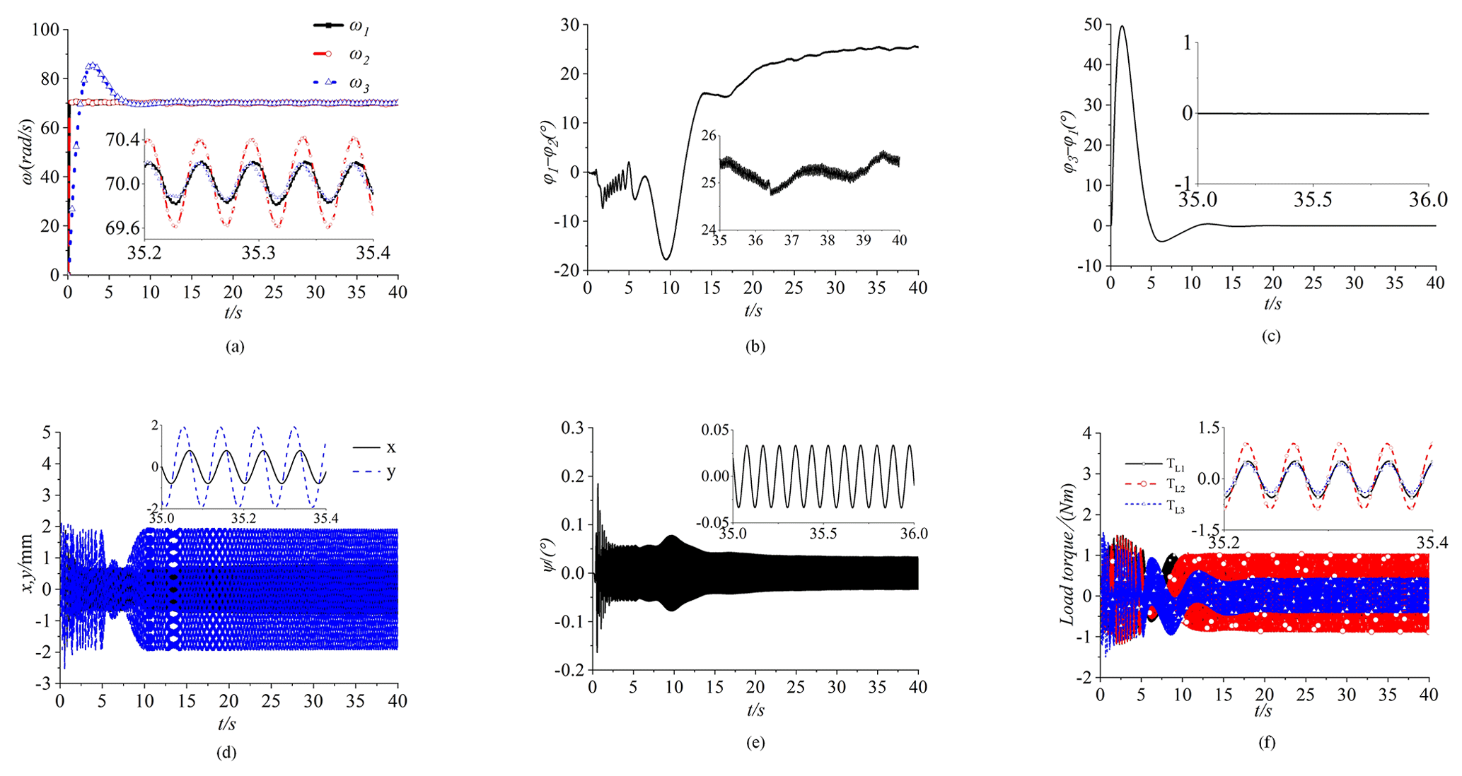
Figure 4Simulation results of the composite synchronization ( = 0.5, l1=l2 = 0.32 m, and l3 = 0.3 m). (a) Speed, (b) phase difference between motors 1 and 2, and (c) phase difference between motors 1 and 3. (d) Responses in the x and y directions. (e) Response in the ψ direction. (f) The load torques of the three motors.
Due to the fact that, for the vibration direction, depending on the excitation force generated by the motors, the amplitudes of the responses in the y direction are larger than those in the x and ψ directions. The scope of responses in the y direction is from −2 to 2 mm. The amplitude of the responses in the x direction is smaller than that in the y direction, which means that the vibration system can realize vibration in the y direction. From the above analyses, the simulation of a composite synchronization motion is realized successfully. The proposed control method shows an excellent performance in the simulations, and the vibration motion in the y direction is achieved.
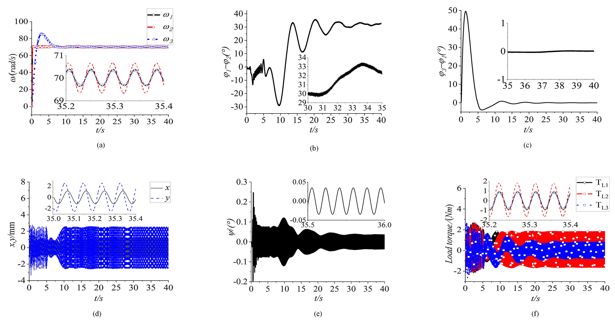
Figure 5Simulation results of the composite synchronization ( = 0.67, l1=l2 = 0.32 m, and l3 = 0.3 m). (a) Speed, (b) phase difference between motors 1 and 2, and (c) phase difference between motors 1 and 3. (d) Responses in the x and y directions. (e) Response in the ψ direction. (f) The load torques of three motors.
In order to study the influence of different factors on the control system. The quality of three ERs is changed to 4 kg, namely ηi=0.67. In Fig. 5a, the rotational speeds of three motors are shown, and three speed curves almost coincide to 70 rad s−1. Comparing with the Fig. 4a, the rotational speed of three motors is not changed. From Fig. 5b, the phase difference in motor 1 and motor 2 is shown. The values of φ1−φ2 stabilize around 32∘ finally, which means that self-synchronous motion is realized. In Fig. 5c, the curve of φ3−φ1 is displayed. The values of φ3−φ1 stabilize around 0∘ ultimately. It means that the change in the quality of ERs will not affect the synchronization of zero-phase difference. The arbitrariness of the proposed control method is illustrated. In Fig. 5d–e, the responses of the vibration system in the x, y, and ψ directions are shown. The values of the responses in the y direction vary from about −3 to 3 mm. With the increase in the ERs quality, the response in the y direction is larger than that in Fig. 4d. From Fig. 5f, the load torques of three ERs are shown.
Obviously, with the increase in the quality of three motors, the load torques have been improved obviously. From the simulation results, with the increase in the quality of ERs, the response of the vibration system in the y direction have obviously enhanced, but the self-synchronous phase difference is increased apparently. The increase in the self-synchronization phase difference is not the desired result in this paper.
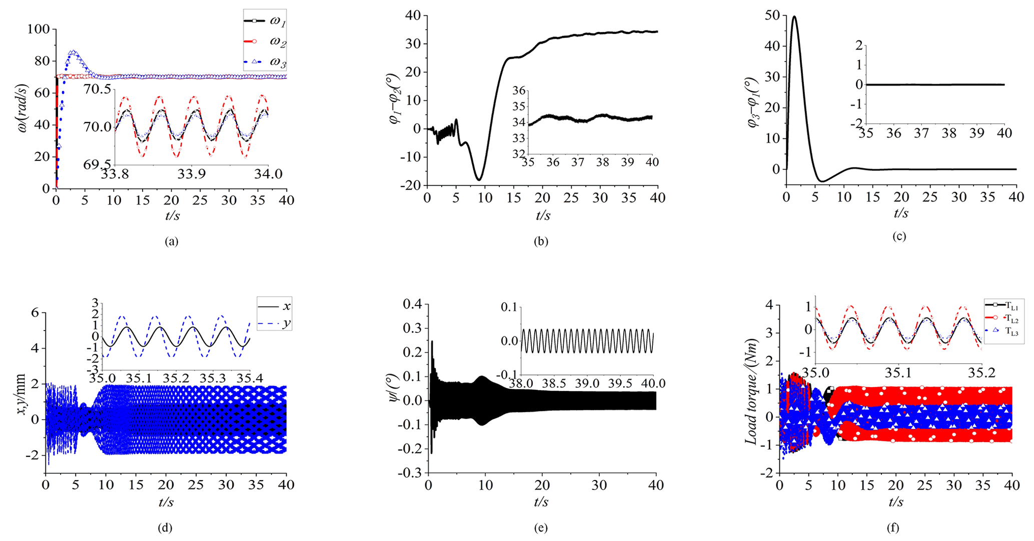
Figure 6Simulation results of the composite synchronization ( = 0.5, and = 0.4 m). (a) Speed, (b) phase difference between motors 1 and 2, and (c) phase difference between motors 1 and 3. (d) Responses in the x and y directions. (e) Response in the ψ direction. (f) The load torques of three motors.
In order to study the influence of the installation position of three motors on a vibration system, the distance between the rotation center of the motors and the center of mass of the vibration system is changed, namely = 0.4 m. The simulation results are as follows. In Fig. 6a, three motors are started smoothly, and their speed eventually reached about 70 rad s−1. In Fig. 6b, the curve of φ2−φ1 is shown. The values of φ2−φ1eventually reached about 34∘, which means that the synchronous motion of motor 1 and motor 2 is achieved, but the self-synchronization phase difference has changed obviously, compared with Fig. 5b. From Fig. 6c, the phase difference in motor 3 and motor 1 is shown. The values of φ3−φ1 are ultimately reached at 0∘, which once again proves the ability of the control method to resist varying parameters. In Fig. 6d–e, the responses in different directions are shown. The response in the ψ direction is still small, floating at around 0∘. The values of the responses in the y direction vary from −2 to 2 mm and are larger than those in the x direction. In Fig. 6f, the load torques of three motors are changed slightly. The values of the load torque of the three motors change from −1 to 1 Nm.
The installation position of the motors has a certain influence on the response of the vibration system and the self-synchronous motion state. With the increase in the installation distance of three motors, the responses in the y direction have not enhanced, but the self-synchronization phase difference has increased. There is no favorable influence on the vibration system with the increase in the installation distance of motors. The proposed control method still shows the ability to resist the changes in various parameters.
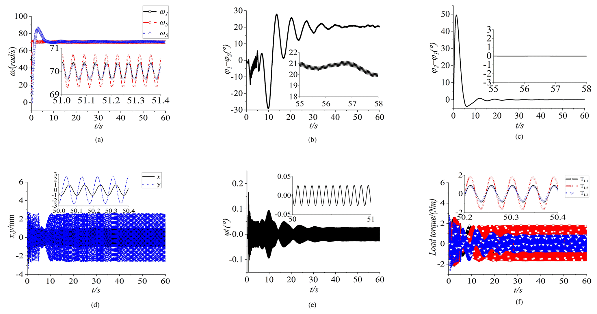
Figure 7Simulation results of the composite synchronization ( = 0.67, l1=l2 = 0.32 m, and l3 = 0.2 m). (a) Speed, (b) phase difference between motors 1 and 2, and (c) phase difference between motors 1 and 3. (d) Responses in the x and y directions. (e) Response in the ψ direction. (f) The load torques of three motors.
Based on the above simulation conclusions, the quality of three ERs is selected as 4 kg, namely ηi = 0.67. The installation position of motors 1 and 2 is unchanged, but the installation distance of motor 3 is reduced, namely l1=l2 = 0.32 m, and l3 = 0.2 m. The simulation results are as follows. In Fig. 7a, the speed of three ERs is about 70 rad s−1. From Fig. 7b, the phase difference of φ1−φ2 stabilizes at 20∘. The values of φ1−φ2 are smaller than those in the above simulations, which means that the synchronization state of the system is more stable. Under the influence of the circumferential distribution of the three motors, the self-synchronization phase differences of φ1−φ2 always exist in the simulations. However, the self-synchronization with a zero-phase difference can be realized (in theory) by adjusting parameters. In Fig. 7c, the control synchronous phase difference of φ1−φ3 still reaches 0∘. This is undoubtedly the control effect of the proposed control method on the system. In Fig. 7d, the responses in the x and y directions are shown. The responses in the y direction vary from −3 to 3 mm, which means that the vibration motion in the y direction is stronger than that in previous simulations. The response in the x direction is smaller than that in the y direction. In Fig. 7e, the responses in the ψ direction are not equal to 0∘. From Fig. 7f, the load torques of three motors are shown. The curves of the load torque are similar to those in Fig. 5f, which indicates that the load torques are mainly influenced by the quality of the ERs.
From the above simulation results, the influence of the quality of ERs and the motor installation position on the vibration system are discussed, respectively. Through many simulation tests, the ideal motion state of the vibration system shows that, with bigger responses in the y direction and a smaller self-synchronization, the phase difference can be obtained.
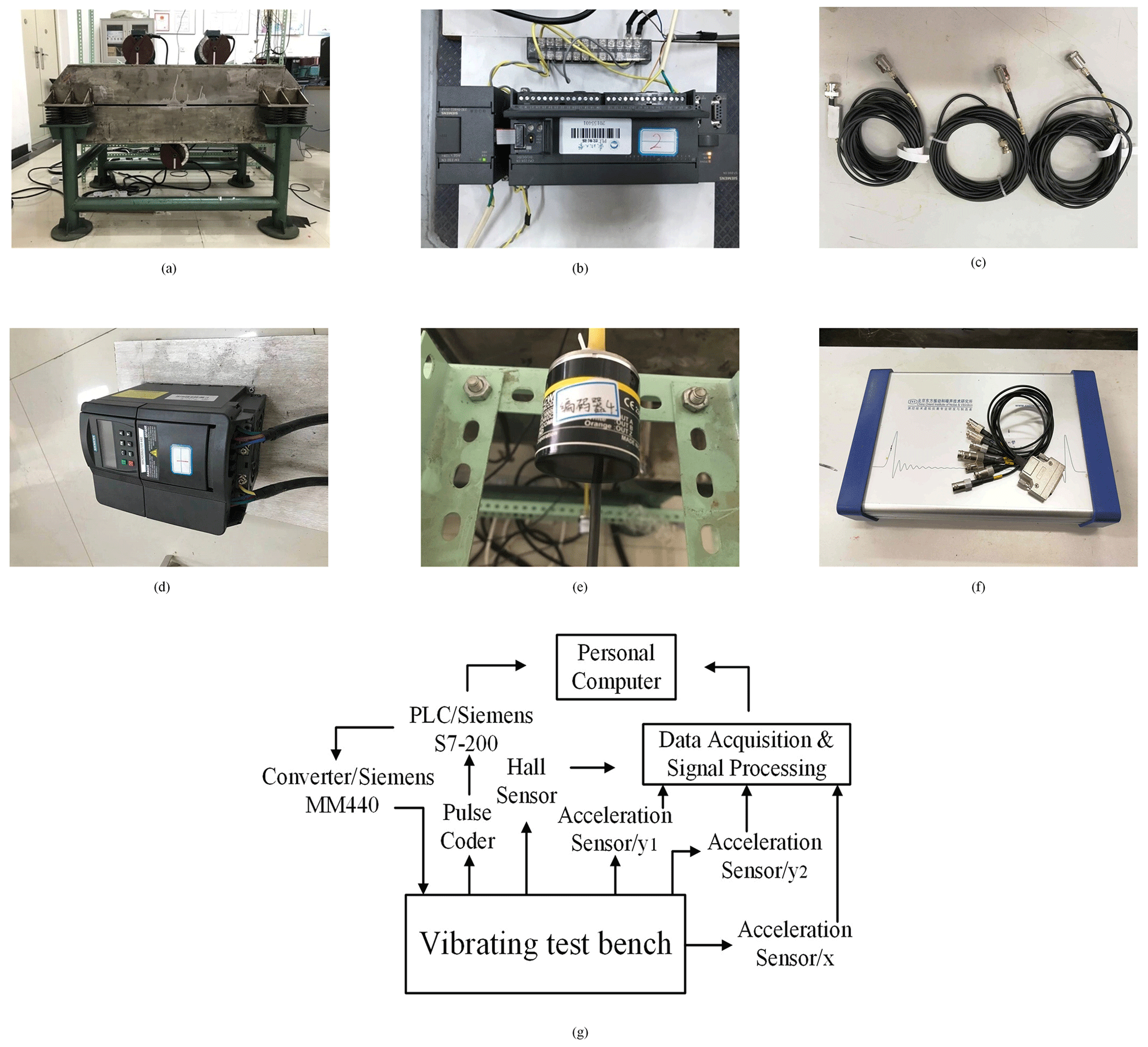
Figure 8Experimental equipment. (a) Vibration test bench, (b) programmable logic controller, (c) acceleration sensor, (d) frequency converter, (e) photoelectric encoder, and (f) signal acquisition instrument. (g) Flow chart of experiment.

Figure 9Experimental results of the composite synchronization ( = 0.5, l1=l2 = 0.32 m, and l3 = 0.3 m). (a) Speed, (b) phase difference between motors 1 and 2, and (c) phase differences between motors 1 and 3. (d) The acceleration in the x direction, (e) the acceleration in the y1 direction, and (f) the acceleration in the y2 direction.
5.2 Composite synchronization experiment
In this section, based on the simulations, the composite synchronization experiments are given to prove the correctness of the theoretical analysis and the numerical simulations based on = 0.5, l1=l2 = 0.32 m, and l3 = 0.3 m. Figure 8a shows the vibration test bench driven by three ERs. Motor 2 rotates counterclockwise, and motors 1 and 3 rotate clockwise. The three motors are distributed circumferentially. Four symmetrical springs link the vibration test bench to the ground, and the vibration test bench can realize the vibration motion in different directions. In Fig. 8b, the programmable logic controller (PLC) is shown. The PLC (Siemens S7-200) is the core of the control synchronization, which can accomplish the control of the phase difference in ERs. Figure 8c shows the acceleration sensor. Three acceleration sensors are installed in the horizontal direction and on the sides of the vibration test bench, respectively, to measure the acceleration of the test bench. The frequency converter (Siemens MM440) is shown in Fig. 8d. Figure 8e shows the photoelectric encoder, which converts mechanical variables into photoelectric signals, and the signal acquisition instrument is shown in Fig. 8f. The scheme of the composited synchronization experiment of the three motors is shown in Fig. 8g. The equipment in the experimental flow chart is mainly composed of a personal computer, a PLC, a converter, an acceleration sensor, and a data acquisition machine.
Through three pulse encoders, the frequencies of the three motors are adjusted. The pulse encoder transmits the signal to the personal computer by connecting with PLC. At the same time, the PLC adjusts the motion state of the vibration test bench through a converter. Three acceleration sensors are placed on the vibration test bench to measure the acceleration in the y1, y2, and x directions, and through data acquisition and signal processing, the acceleration information is collected on the personal computer. The pulses are obtained by a Hall effect sensor detecting the switching signal for every lap of the three ERs. The pulses are converted to the calculation data by the pulse coder and PLC. The frequencies of three motors are set as 35 Hz, coinciding with the simulation values. From Fig. 9a, the rotational speeds of three motors are shown. When t≈8 s, then three motors are started simultaneously. While t≈12 s, ω1, ω2 and ω3 reach stable values and fluctuate around 73 rad s−1. The phase difference in motors 1 and 2 is shown in Fig. 9b. At the beginning, motors 1 and 2 are in a stationary state, and the values of φ1−φ2 are chaotic. When the time is at 25 s, the synchronization state is stable, and the self-synchronization phase has difference values that fluctuate around about 33∘. Although there is a certain error with the simulation results in Fig. 4b, the error may be caused by the external working environment. The self-synchronization motion between motor 1 and motor 2 is achieved. In Fig. 9c, the phase difference in motors 1 and 3 is shown. Under the disturbance factor of the motor parameters and the parameters of the vibration test bench, the control synchronization phase difference is chaotic at the beginning. When the time is at about 30 s, φ1−φ3 stabilizes at about 0∘. Motor 1 and motor 3 operate the control in a synchronous motion with an approximate zero-phase difference, which validates the effectiveness and necessity of the proposed controller to implement control synchronization.
The excitation force generated from three motors affects the characteristics of the vibration system, and the vibration system affects the motors by altering the load torques of the motors. The vibration motion of the system is directly caused by the responses in the x, y, and ψ directions. From Fig. 9d–f, the amplitudes of acceleration are shown. The accelerations of and are about 12 m s−2, and is about 7 m s−2. The reason for this phenomenon is that the addition of an excitation force for three motors in the y direction causes larger than . Because motor 1 and motor 2 are installed on the vibration test bench symmetrically, so .
From the above analysis, the experiment results are almost in accord with the simulation results in Fig. 4, which firmly confirms the practicability of the proposed control method.
In this article, the composite synchronization of three inductor motors with a circular distribution by a fuzzy PID method in a vibration system is investigated. The fuzzy PID method proposed is based on a master–slave strategy that has been established. The stability analysis, based on the Lyapunov theorem of the controlling method, is certified. The phase differences in the self-synchronization and controlled synchronization are measured and compared based on simulation and experiment results. The vibration direction is determined by the direction of the resultant forces provided in the vibration system. Numerical simulations and experiment results illustrate that motor 1 and motor 2 can realize the stable self-synchronization motion. Motors 1 and 3 can realize the controlled synchronization with zero-phase difference. It is indicated that the controlling method proposed has a strong robustness in the composite synchronization motion against some internal perturbations and external time-varying disturbances. Through changing the characteristic parameters in the simulations, the results indicate that the response amplitude can be influenced by the parameters li and mi. To obtain the trajectory of straight line in the y direction, which is needed for the engineering, the phase difference between motors 1 and 2 should be reduced, and mi should be increased. When the parameters l1 and l2 are determined, l3 should be reduced.
| mi | The mass of each ER |
| Jp | The moment of inertia of the rigid body |
| J | The moment of inertia of the vibration system |
| kx, ky, kψ | The damping coefficients of the vibration system in the x, y, and ψ directions |
| r | The eccentric radius of the three motors |
| M | The mass of the total vibration system |
| fx, fy, fψ | The stiffness coefficients of the vibration system in the x, y, and ψ directions |
| l1, l2, l3 | The distance between the center of the body and the rotating center of the motors |
| Ji | The moment of inertia of the inductor motor |
| d, q | The d and q axes in the rotor-field-oriented coordinate |
| Ls | The self-inductance of the stator |
| Lr | The self-inductance of the rotor |
| Subscript s | The stator |
| Subscript r | The rotor |
| Lm | The mutual inductance of the stator and rotor |
| ϕsd | The flux linkages of the stator in the d axis |
| ϕsq | The flux linkages of the stator in the q axis |
| ϕrd | The flux linkages of the rotor in the d axis |
| ϕrq | The flux linkages of the rotor in the q axis |
| Rs | The stator resistance |
| Rr | The rotor resistance |
| isd | The current of the stator in the d axis |
| isq | The current of the stator in the q axis |
| ird | The current of the rotor in the d axis |
| irq | The current of the rotor in the q axis |
| ω | The mechanical speed |
| ωs | The synchronous electric angular speed |
| , , , | The derivation of ϕsd, ϕsq, ϕrd, ϕrq |
| σ | The leakage factor |
| Tr | The rotor time constant |
| usd | The voltage of the stator in the d axis |
| usq | The voltage of the stator in the q axis |
| urd | The voltage of the rotor in the d axis |
| urq | The voltage of the rotor in the q axis |
| np | The number of pole pairs of the induction motor |
| The given values or obtained from the given values | |
| ω1, ω2, ω3 | The speeds of the three motors |
| φ1, φ2, φ3 | The phases of the three motors |
The datasets generated during the current study are available from the corresponding/first author on reasonable request.
LJ wrote the article, JY compiled the figures and tables, XG conducted the simulation, ZL led the experiments, and XM checked the article.
The contact author has declared that none of the authors has any competing interests.
Publisher’s note: Copernicus Publications remains neutral with regard to jurisdictional claims in published maps and institutional affiliations.
The authors extend many thanks to the 2021 Liaoning Education department General Young Project (grant no. LJKZ0259) for making this paper possible. This article has been funded by the 2022 Liaoning Education department General Project (grant no. LJKMZ20220602), and the APC has been funded by the same funder.
This research has been supported by the 2022 Liaoning Education department General Project (grant no. LJKMZ20220602),
This paper was edited by Xuping Zhang and reviewed by two anonymous referees.
Barambones, O. and Alkorta, P.: Position Control of the Induction Motor Using an Adaptive Sliding-Mode Controller and Observers, IEEE T. Ind. Electron., 61, 6556–6565, https://doi.org/10.1109/TIE.2014.2316239, 2014.
Blekhman, I. I., Fradkov, A. L., and Nijmeijer, H.: On self-synchronization and controlled synchronization, Syst. Control Lett., 31, 299–305, https://doi.org/10.1016/S0167-6911(97)00047-9, 1997.
Chen, C. S. and Chen, L. Y.: Robust Cross-Coupling Synchronous Control by Shaping Position Commands in Multiaxes System, IEEE T. Ind. Electron. 59, 4761–4773, https://doi.org/10.1109/TIE.2011.2182012, 2012.
Chen, W., Liang, J., and Shi, T.: Speed Synchronous Control of Multiple Permanent Magnet Synchronous Motors Based on an Improved Cross-Coupling Structure, Energies, 11, 282, https://doi.org/10.3390/en11020282, 2018.
Czolczynski, K., Perlikowski, P., and Stefanski, A.: Synchronization of pendula rotating in different directions, Commun. Nonlinear Sci., 17, 3658–3672, https://doi.org/10.1016/j.cnsns.2012.01.014, 2012.
Goanţă, A. M., Bratu, P., and Drăgan, N.: Dynamic Response of Vibratory Piling Machines for Ground Foundations, Symmetry, 14, 1238, https://doi.org/10.3390/sym14061238, 2022.
Gu, D., Wen, B., and Zhang, J.: Vibratory synchronization transmission of two cylindrical rollers in a super-resonant vibrating system with symmetrical structure, Proceedings of the Institution of Mechanical Engineers, J. Mech. Eng. Sci., 233, 1204–1223, https://doi.org/10.1177/0954406218766965, 2018.
Gu, D., Zhang, X., and Zhang, J.: Synchronization and coupling dynamic characteristics of an exciter and two cylindrical rollers in a vibrating system, J. Sound Vib., 456, 353–373, https://doi.org/10.1016/j.jsv.2019.05.012, 2019.
Gu, D., Zhang, J., Wu, Q., Shen, P., Pan, B., and Wen, B.: Synchronization of an Exciter and Three Cylindrical Rollers with Different Dry Friction via Dynamic Coupling, Appl. Sci., 12, 5239, https://doi.org/10.3390/app12105239, 2022.
Hashimoto, F. and Johnson, S. P.: Modeling of vibratory finishing machines, CIRP Annals, 64, 345–348, https://doi.org/10.1016/j.cirp.2015.04.004, 2015.
Jia, L., Wang, C., and Liu, Z.: Multifrequency controlled synchronization of four inductor motors by the fixed frequency ratio method in a vibration system, Sci. Rep.-UK, 13, 2467, https://doi.org/10.1038/s41598-023-29603-y, 2023.
Jia, Y., Zhang, N., and An, Z.: Self-Synchronization Theory of Circular Symmetrical Four Motors, J. Phys. Conf. Ser., 2174, 012078, https://doi.org/10.1088/1742-6596/2174/1/012078, 2022.
Kong, X. and Wen, B.: Composite synchronization of a four eccentric rotors driven vibration system with a mass-spring rigid base, J. Sound Vib., 427, 63–81, https://doi.org/10.1016/j.jsv.2018.04.002, 2018.
Kong, X., Chen, C., and Wen, B.: Composite synchronization of three eccentric rotors driven by induction motors in a vibrating system, Mech. Syst. Signal Pr., 102, 158–179, https://doi.org/10.1016/j.ymssp.2017.09.025, 2018.
Li, L., Sun, L., and Zhang, S.: Mean deviation coupling synchronous control for multiple motors via second-order adaptive sliding mode control, ISA T., 62, 222–235, https://doi.org/10.1016/j.isatra.2016.01.015, 2016.
Liu, M., Gu, F., and Huang, J.: Integration Design and Optimization Control of a Dynamic Vibration Absorber for Electric Wheels with In-Wheel Motor, Energies, 10, 2069, https://doi.org/10.3390/en10122069, 2017.
Rao, G., Chaudhary, H., and Sharma, A.: Design and Analysis of Vibratory Mechanism for Tillage Application, Open Agric., 3, 437–443, https://doi.org/10.1515/opag-2018-0048, 2018.
Sun, D.: Position synchronization of multiple motion axes with adaptive coupling control, Automatica, 39, 997–1005, https://doi.org/10.1016/S0005-1098(03)00037-2, 2003.
Wei, M.-Y., Yeh, Y.-L., and Liu, J.-W.: Design and Control of a Multi-Axis Servo Motion Chair System Based on a Microcontroller, Energies, 15, 4401, https://doi.org/10.3390/en15124401, 2022.
Zhang, N., Wu, S., and Li, Y.: Synchronous Behavior Analysis of Two Rotors in Self-synchronization System, IOP Conf. Ser.-Mat. Sci., 631, 032013, https://doi.org/10.1088/1757-899X/631/3/032013, 2019.
Zhang, X., Wen, B., and Zhao, C.: Synchronization of three homodromy coupled exciters in a non-resonant vibrating system of plane motion, Acta Mech. Sinica, 28, 1424–1435, https://doi.org/10.1007/s10409-012-0151-2, 2012.
Zhang, X., Wen, B., and Zhao, C.: Synchronization of three non-identical coupled exciters with the same rotating directions in a far-resonant vibrating system, J. Sound Vib., 332, 2300–2317, https://doi.org/10.1016/j.jsv.2012.12.003, 2013a.
Zhang, X., Wen, B., and Zhao, C.: Theoretical, numerical and experimental study on synchronization of three identical exciters in a vibrating system, Chin. J. Mech. Eng., 26, 746–757, https://doi.org/10.3901/CJME.2013.04.746, 2013b.
Zhang, X., Wen, B., and Zhao, C.: Vibratory synchronization and coupling dynamic characteristics of multiple unbalanced rotors on a mass-spring rigid base, Int. J. Nonlin. Mech., 60, 1–8, https://doi.org/10.1016/j.ijnonlinmec.2013.12.002, 2014.
Zhang, X., Wen, B., and Zhao, C.: Vibratory synchronization transmission of a cylindrical roller in a vibrating mechanical system excited by two exciters, Mech. Syst. Signal Pr., 96, 88–103, https://doi.org/10.1016/j.ymssp.2017.04.007, 2017.
Zhao, C., Wen, B., and Zhang, X.: Synchronization of the four identical unbalanced rotors in a vibrating system of plane motion, Sci. China Technol. Sc., 53, 405–422, https://doi.org/10.1007/s11431-009-0376-x, 2010.
Zhao, C., Zhao, Q., and Gong, Z.: Synchronization of Two Self-Synchronous Vibrating Machines on an Isolation Frame, Shock Vib., 18, 904204, https://doi.org/10.3233/SAV-2010-0591, 2011a.
Zhao, C., Zhao, Q., and Zhang, Y.: Synchronization of two non-identical coupled exciters in a non-resonant vibrating system of plane motion, J. Mech. Sci. Technol., 25, 49–60, https://doi.org/10.1007/s12206-010-1101-1, 2011b.
- Abstract
- Introduction
- The mathematical model of the vibratory system
- The control synchronization of three induction motors
- Design of the fuzzy PID method
- Results and discussion
- Conclusions
- Appendix A
- Appendix B
- Appendix C: Nomenclature of the symbols
- Data availability
- Author contributions
- Competing interests
- Disclaimer
- Acknowledgements
- Financial support
- Review statement
- References