the Creative Commons Attribution 4.0 License.
the Creative Commons Attribution 4.0 License.
 | 05 Jan 2023
Research on obstacle performance and tipping stability of a novel wheel–leg deformation mechanism
Minghui Zhang
Yiming Su
A new type of wheel–leg deformation mechanism, based on an electromagnetic clutch and gear rack transmission mechanism, is designed. This mechanism has a compact structure and simple operation, which can roll on wheels and surmount obstacles with a support leg. Firstly, the walking model is established to study the kinematics characteristics of the mechanism. The alternation of the support legs does not affect smooth obstacle crossing, but will cause the step change of the angular velocity of the centroid of the main body. Secondly, the obstacle-surmounting performance of roll-over mode and obstacle-crossing mode using support legs is analyzed. For roll-over mode, the maximum climbing height is 87.36 mm. For obstacle-crossing mode using support legs, the maximum climbing height is the maximum extension length of the support leg. According to the climbing height, the switching criteria of different climbing modes are obtained. In addition, the rolling angle of the main body has a greater impact on the support force and driving torque, while the contact angle between the legs and the ground has a small impact. Finally, the tipping stability and anti-interference ability of the wheel–leg deformation mechanism is evaluated using the stability cone method.
- Article
(13658 KB) - Full-text XML
- BibTeX
- EndNote


Exploiting the structural deformation principle, the wheel–leg deformation mechanism integrates the wheel mechanism and the leg mechanism. With the help of deformation or switching between the wheels and the legs, the wheel–leg mobile mechanism possesses two motion modes: wheel rolling and leg obstacle walking, which not only retains the excellent obstacle-crossing performance of the leg mechanism, but also has the rapid movement ability of wheel rolling. Thus, the wheel–leg mechanism has good adaptability to complex road environment.
In the early stage, the wheel–leg variant mechanism mostly adopted the structure of rolling wheel deformation: the semicircular wheel was used as the actuator of wheel–leg deformation switching. Sun et al. (2022) proposed a wheel–leg mechanism composed of involute curve and circular arc, which can walk, run, and cross obstacles in rough terrain. Yuan et al. (2022) designed a semicircle arc wheel–leg deformation mechanism based on the transformation of multi-link structure, which can realize the sliding of round pipe and the leg-type obstacle-crossing movement according to different environments. In addition, Vina and Barrientos (2021) and Yamamoto and Aoki (2020) have studied the C-leg hybrid mobile robot: on flat ground, it can roll smoothly; and when climbing the boss, the end of the semicircular wheel is used as the support leg and the front wheel and the rear wheel of the vehicle body crosses the obstacle alternately in a butterfly gait. Tan et al. (2019) designed a wheel–leg reconfigurable robot, which uses the semicircular wheel as the leg of the robot, and in the meantime, two semicircular wheels on the same side rotate to form a wheel structure. Wang and Lin (2021) and Lin et al. (2018) proposed a wheel–leg deformable robot named turboquad. The wheel–leg structure adopts the transformation mode of vertical I-shape separation of two semicircular wheel–legs to ensure continuous movement. Chen et al. (2021) used the double-link mechanism as a semicircular rim. When the motor drives, two V-shaped links to extend, and the rolling wheels are switched from the wheel type state to the V-shaped leg type state. Ning et al. (2017) designed a wheel–leg rescue robot with double semi-circular arc hub structure. If the semicircular wheel hub is closed, the robot is in wheel motion mode. If the semicircular wheel is folded along the central axis, the robot is in leg motion mode.
When crossing vertical obstacles or irregular obstacles such as steps and bosses, the semi-circular wheel structure is not stable enough. Researchers have been improving the deformation mechanism of the wheel–legs. Ding and Zhang (2022) designed a variable diameter wheel–leg obstacle-surmounting robot. Three groups of arc legs are driven to extend outward by connecting rod transmission to realize diameter change. When the arc legs retract the hub, they switch to wheel type state. Zhang et al. (2021) proposed a wheel-leg switching mode with scissors structure. The wheel–leg mobile robot designed by Xu et al. (2021) has three groups of arc-shaped legs that can protrude from the inside of the rolling wheel with the help of the four-bar structure, the robot is able to switch to the leg-type obstacle-crossing movement mode. The wheel–leg deformation robot developed by Ryu et al. (2020) uses the wheel rotation to generate centrifugal force, so that the mechanism is transformed from the wheel shape to the arc wheel–leg shape. Teng (2020) and Kim et al. (2020, 2019) divide the rolling wheels into three groups of arc wheels as the leg structure of the robot. By controlling the expansion and contraction of the link structure, the robot can switch between the wheel mode and leg mode. Cong et al. (2021) used a plane spiral pair to transmit the rotational power to the arc-shaped wheel–legs, the rolling wheel was switched from the round wheel state to four groups of arc-shaped wheel–legs. The wheel–leg transformation robots designed in the references Lee et al. (2022), Lv (2020), Zeng et al. (2019), and Mertyüz et al. (2020) adopt six wheel–legs arranged in the circumferential direction, and each wheel–leg can be independently transformed during obstacle crossing. In addition, Tholapu et al. (2021) proposed a conceptual spherical mobile robot, which is composed of two hemispheres, and each hemisphere is divided into four legs. In the status of stretching, the robot can walk like a quadruped robot, and while closing into a sphere, the robot can roll. Zhai et al. (2021) designed a wheel–leg variable robot based on the principle of iris structural deformation. The robot can roll forward on the flat ground and can switch to the petal leg obstacle mode when encountering obstacles.
In addition to the wheel–leg deformation robot that directly transforms the hub into a leg, there is another kind of wheel-legged variant mobile robot that includes the leg structure in the rolling wheel or the fuselage. When the robot encounters obstacles, the leg structure is driven by the transmission mechanism to extend from the rolling wheel or the fuselage. When the ground is flat, the leg structure is retracted into the rolling wheel or the fuselage internal structure. This kind of robot can switch the movement mode autonomously according to the environment and has stronger adaptability and stability. The 2-DOF motion robot designed by Zhang (2021) and Zhang and Sun (2021) is composed of rolling wheels and telescopic adjustable links. Baishya et al. (2021) proposed an anti-skid mechanism for climbing steps, consisting of three motion chains and four-bar mechanism, which controls the mutual switching between the rolling wheel and the structural leg by using the current thermal effect and the elastic potential energy of the spring. The wheel–leg mobile robot designed by Sanchez and Bhounsule (2021) is composed of several adjustable telescopic legs. When crossing the obstacle, the robot realizes rotation and climbing by means of the contact point between the end of the leg and the obstacle. Xie et al. (2021) proposed a new type of two-way inchworm pipeline robot, which drives the leg structure to expand and contract through the rotation of the cam to realize the two-way crawling of the robot in the pipeline. In the spherical quadruped robot studied by Aoki et al. (2020), the legs alternately extend from the inside of the spherical shell and kick to the ground when climbing steps, pushing the fuselage to climb over the steps. Song et al. (2022) proposed a wheel–leg deformation structure, which drives the sliding leg to extend from the guide rail through the crank linkage mechanism to complete the switch from wheel type to spoke leg type structure.
The scholars have done a lot of work on the wheel–leg variant mobile robot, which mainly focuses on the design and kinematic analysis of the new wheel–leg deformation mechanism. However, there are still problems such as the wheel–leg deformation mechanism being too complex and the wheel–leg switching criteria lacking theoretical basis. In addition, there is little analysis on the motion stability and anti-interference ability of the wheel–leg deformation mechanism. Therefore, the following work has been done in this paper: (1) a new type of wheel–leg deformation mechanism with compact structure and simple operation has been designed. The mechanism can roll on wheels and surmount obstacles with support leg mode by means of electromagnetic clutch and gear rack transmission mechanism. (2) The walking model is established to study the kinematic characteristics and obstacle-surmounting performance of the mechanism. The wheel-legged switching criterion of mechanism is formulated. (3) The stability cone method is used to evaluate the rollover stability and anti-interference ability in order to ensure the normal operation of the mechanism.
The paper is organized as follows: Sect. 2 first outlines the structure of the wheel–leg deformation mechanism and the working principle of wheel–leg switch. Section 3 describes the obstacle-surmounting performance and tipping stability of the mechanism. Finally, the findings of the present study are concluded.
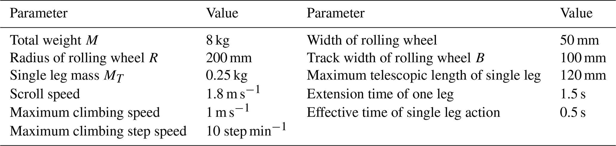
A new type of wheel–leg deformation mechanism is proposed, which has strong adaptability to complex terrain and can cross over gullies, climb up and down steps, and roll on flat roads. According to the requirements of the application environment of the mechanism, the mass of the wheel–leg deformation mechanism should not be greater than 10 kg, the rolling speed of the flat ground should not be less than 1.5 m s−1, the climbing angle should not be less than 10∘, the climbing speed should not be less than 0.5 m s−1, the climbing step speed in the leg state should not less than 10 steps min−1, the climbing step height should not be less than 200 mm, and the width of the crossing gully shall not be less than 200 mm.
2.1 Structural design of wheel–leg deformation mechanism
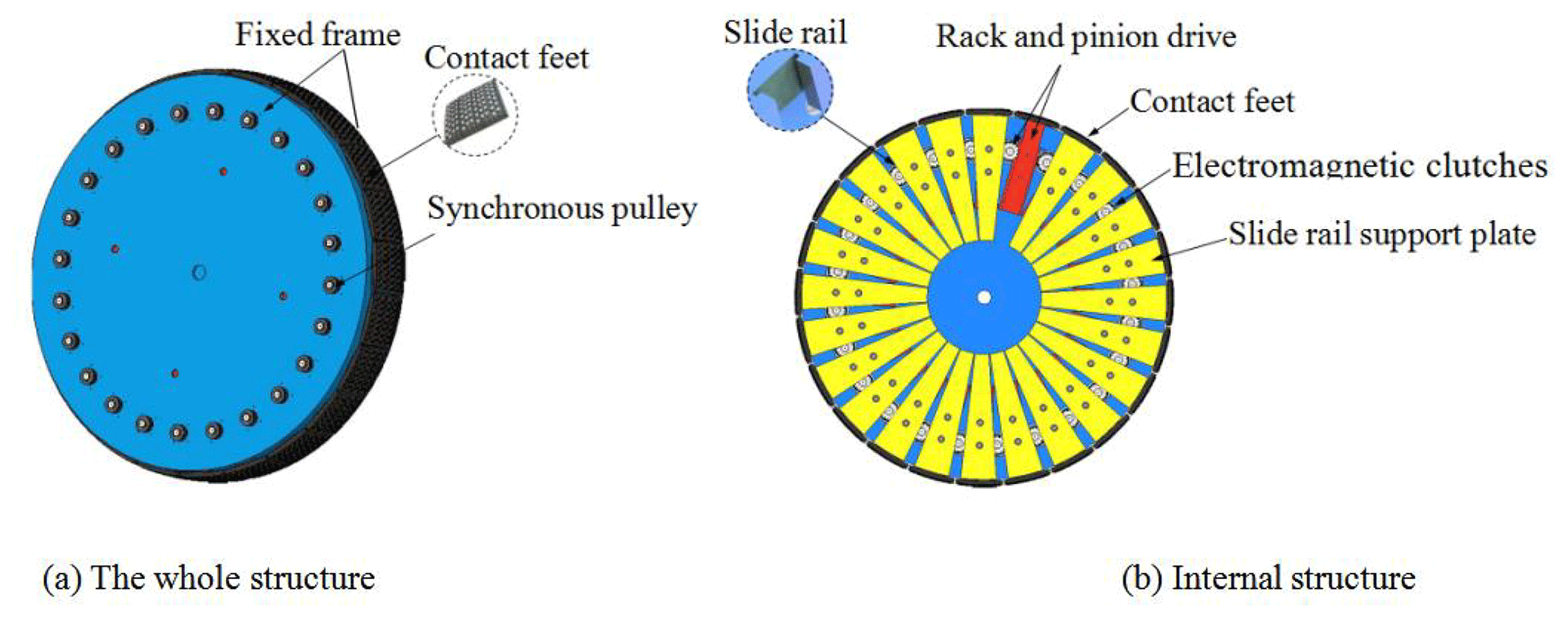
The leg telescopic structure is composed of two sets of fixed frames and 24 contact feet, as shown in Fig. 1a. Each set of fixed frames includes one fixed disk and 24 gears, racks, sliding support plates, and electromagnetic clutches, which are evenly distributed along the circumferential direction, as shown in Fig. 1b. Connect the same direction rack on the two sets of fixed frames with the contact foot through bolts to form a telescopic leg. The electromagnetic clutch cooperates with the gear and rack to realize the independent movement of each telescopic leg.
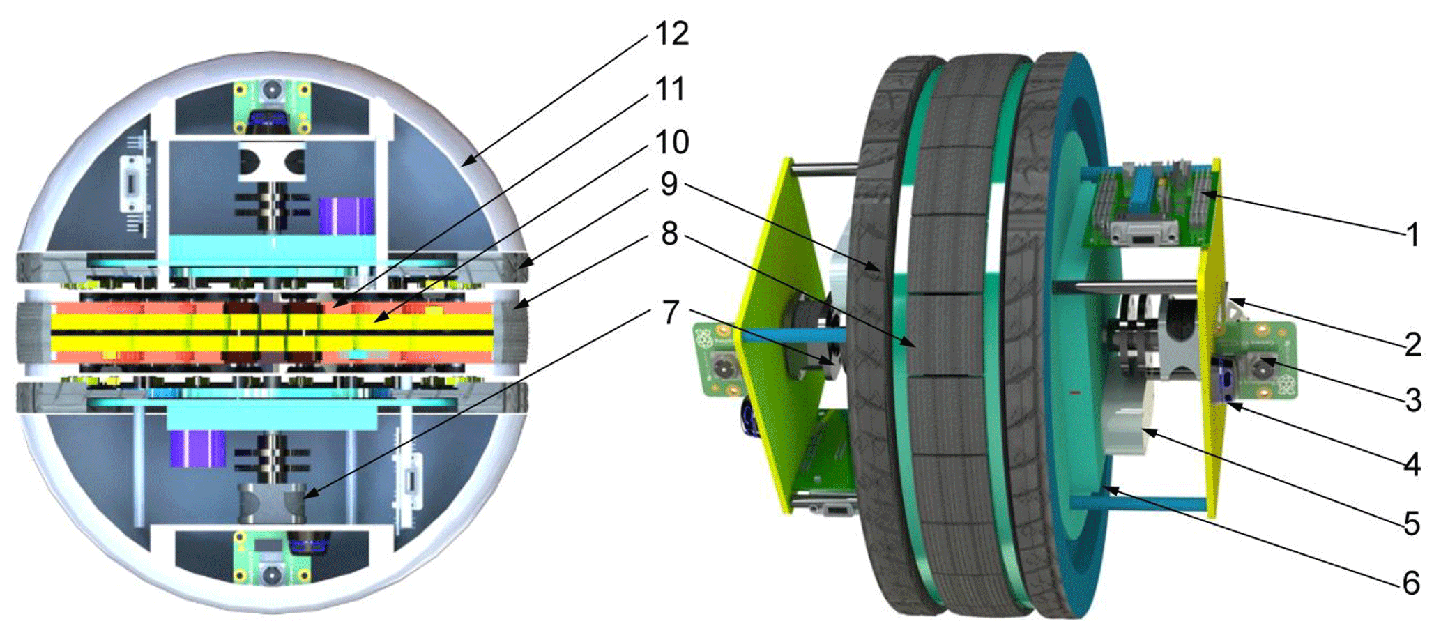
The overall structure of the wheel–leg deformation mechanism is shown in Fig. 2. The whole deformation mechanism includes the following: (1) control unit; (2) inertial measurement unit; (3) vision sensor; (4) laser radar; (5) lithium battery; (6) sealing cover; (7) drive motor; (8) leg contact foot; (9) rolling wheel; (10) slide rail support plate; (11) rack; and (12) enclosure. Relevant design parameters of wheel–leg deformation mechanism are shown in Table 1.
2.2 Mechanism of wheel-legged movement mode switching
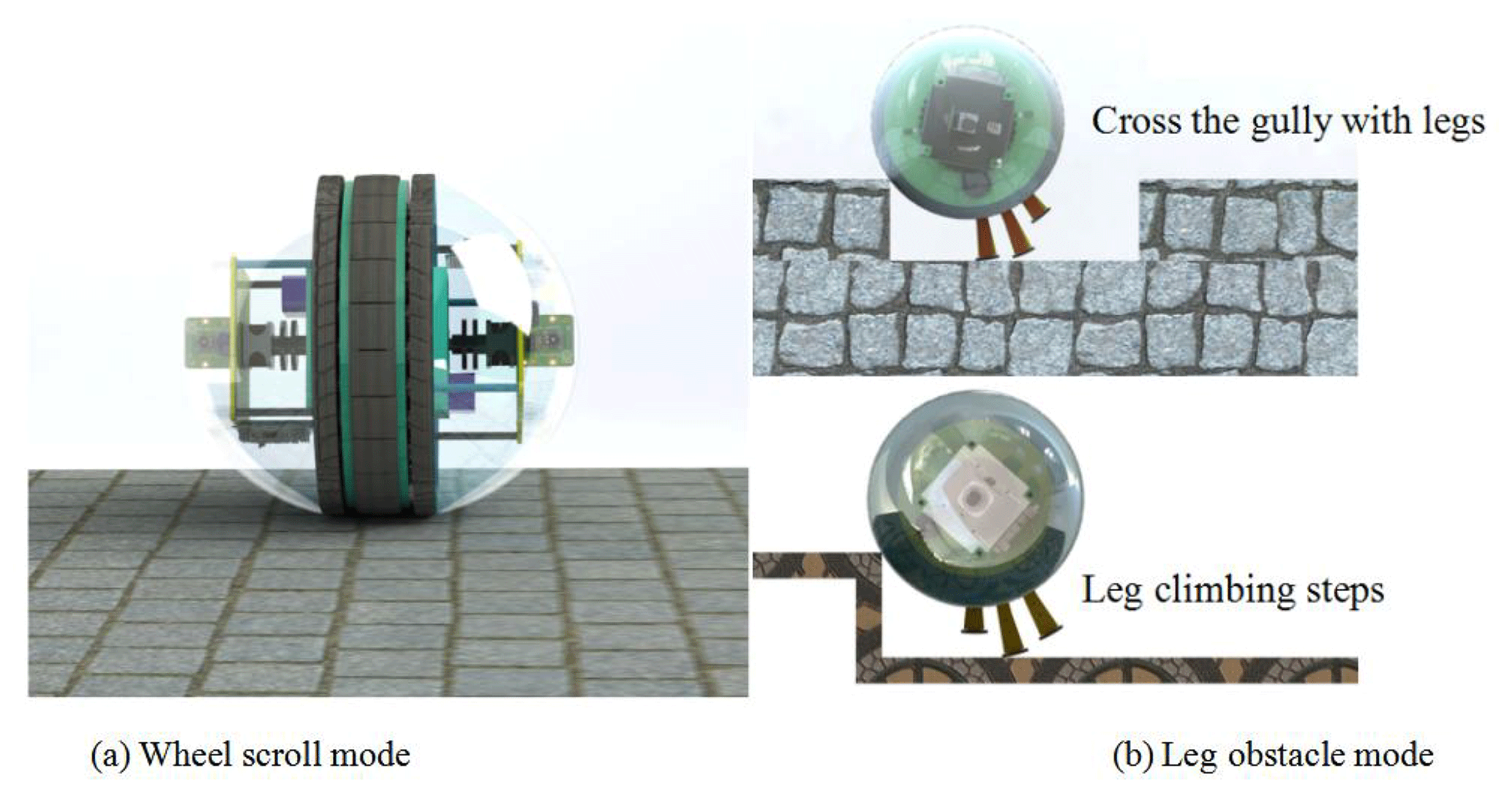
According to the application scenarios and design requirements of the wheel–leg deformation mechanism, the mechanism rolls forward on the flat road, as shown in Fig. 3a. When the rolling wheel cannot cross complex road conditions such as steps and gullies, it will switch to the leg type obstacle-crossing mode, as shown in Fig. 3b.
The following will introduce the working principles of the two motion modes in combination with the internal transmission system diagram of the mechanism, as shown in Fig. 4. Where I is the motor input shaft; A, B, C, and D are electromagnetic clutches; 1 is driving center wheel in leg mode; 2 is driving center wheel in rolling mode; 3, 4, 8, and 9 are gears; 5 is a rolling wheel; and 6 and 7 are timing pulleys.

2.2.1 Wheel scroll mode
The motor transmits the driving torque to the input shaft I, and the electromagnetic clutch A is energized. The power drives the rolling wheel 5 to rotate through the sun gear 2 and the planetary gear 4. Since the electromagnetic clutch B is in the power-off state, the driving torque cannot be transmitted to the synchronous pulley at the lower side of the electromagnetic clutch B, and the leg structure contracts inside the deformation mechanism, so that the mechanism can roll forward on the flat ground.
2.2.2 Leg obstacle mode
When the wheel–leg deformation mechanism encounters an obstacle that the rolling wheel cannot climb over, the electromagnetic clutch A is powered off, and the electromagnetic clutch B is switched from the power-off state to the power-on state. After the motor is regulated, the driving torque is transmitted to the lower synchronous pulley 6 of the electromagnetic clutch B through the gear 3 of the planetary gear train. The electromagnetic clutch C is energized, and the power is transmitted to the rack meshing with the gear 8 via the timing pulley 7, and the contact foot is extended. When the travel switch installed at the end of the rack is touched, the electromagnetic clutch B is cut off, the electromagnetic clutch D on the opposite side is energized, and the leg structure is retracted inside the mechanism.
2.3 Gait planning of legged obstacle walking
When the wheel–leg deformation mechanism encounters steps and gullies, the contact feet extend alternately to push the body upward. According to the nomenclature principle of leg mechanism, the contact legs extending alternately are defined as support legs and swing legs. The contact foot that is far away from the step, in contact with the ground, and plays a supporting role is called the support leg, and the contact foot that is near the step, in the extended state, and is not in contact with the ground is called the swing leg. Take climbing steps as an example, the obstacle-crossing process is divided into four stages: (1) the stage of the support leg 1 extension. When the body of the deformation mechanism touches the step, the contact foot (in the opposite direction of movement) closest to vertical line through centroid extends and the contact foot (support leg 1) collides with the ground to trigger the extension of its adjacent inner contact foot (swing leg 1), as shown in Fig. 5a. (2) The support leg 1 supports and pushes the fuselage upward. Support leg 1 extends to the maximum elongation, and then swing leg 1 contacts the ground, as shown in Fig. 5b. (3) The swing leg 1 is converted into a support leg 2. After the swing leg 1 contacts the ground, the support leg 1 retracts and the swing leg 2 starts to extend. The swing leg 1 supports and pushes the fuselage upward as the support leg 2, as shown in Fig. 5c. (4) Repeat the above process until the center of mass of the body crosses the boundary line of the obstacle, the contact foot retracts and climbs up the obstacle with the body, as shown in Fig. 5d.
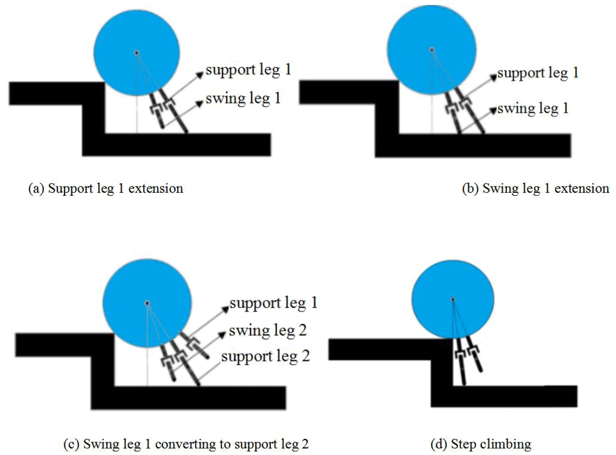
When the wheel–leg deformation mechanism goes down the step, the movement process of its leg structure is opposite to that of the upper step. When the mechanism goes over the gully, it can be regarded as the movement combination of the upper and lower steps.
When the wheel–leg deformation mechanism moves in the complex road environment, it needs to use the leg structure to extend alternately to push the fuselage over obstacles. The obstacle-surmounting performance and stable working conditions of the mechanism are analyzed.
3.1 Kinematic analysis of legged obstacle walking
The schematic diagram of the kth and k+1th movements of the support leg and the swing leg when the wheel–leg deformation mechanism crosses the obstacle is shown in Fig. 6. When the support leg just touches the ground, the extended length is OkAk=lsk, and the included angle between the support leg and the ground is αk. The centroid of the supporting leg extending out of the main body is Ck. The centroid of the body is Ok. The contact point between the mechanism body and the step is point B. The distance between the centroid of the main body and the contact point is BOk=R. The angle between the connecting line BOk and the ground is φk. When the extension of the support leg reaches the maximum, the length is , and the included angle between the support leg and the ground is αk+1. At this time, the swinging leg contacts the ground, and the extension length is . The centroid of the supporting leg extending out of the main body is The centroid of the body is Ok+1. The angle between the connecting line BOk+1 and the ground is φk+1. The coordinate system is established, the motion direction is the x axis, the vertical ground direction is the z axis, the coordinate origin is the contact point between the support leg 1 and the ground.

Assuming that the height of the step is H, the mass of the body is M, and the mass of the single leg is MT, the speed of leg extension is V. Let and . When the wheel–leg deformation mechanism crosses the obstacle, Eqs. (1)–(4) shall be satisfied.
Based on the instantaneous inelastic collision hypothesis, the energy equation and momentum moment equation are established when the support leg touches the ground and the support leg extends to the maximum. The equations are as follows:
It should be pointed out that when establishing the energy equation and momentum equation, only the main body and the supporting leg is considered, and the influence of the swinging leg is ignored. Use “−” to indicate before the impact between the contact foot and the ground occurs, “+” to indicate that the impact is just completed, and “k” to indicate the number of steps.
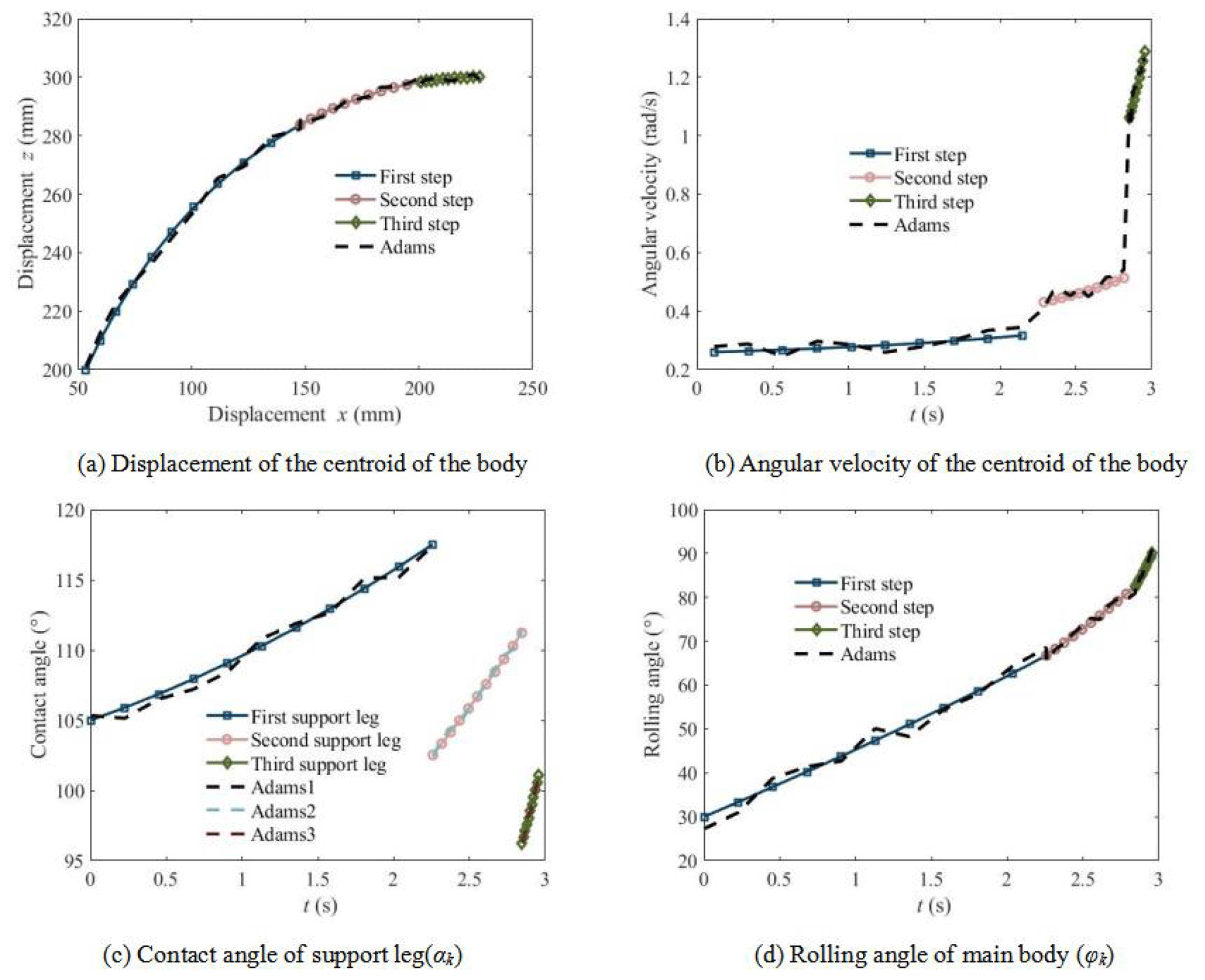
Assume that the step height is 100 mm and the leg extension speed is 50 mm s−1. Combined with the design parameters of the mechanism, the kinematic characteristics of the wheel–leg deformation mechanism over typical obstacles are studied using the above theory. At the same time, the dynamic simulation software ADAMS is used to simulate the actual movement process of the mechanical system to verify the correctness of the leg-type obstacle-climbing theory of the wheel–leg deformation mechanism and the rationality of the mechanical structure design. The comparison between theoretical calculation and simulation analysis results of motion parameters is shown in Fig. 7. It is shown that when climbing a step with a height of 100 mm, the mechanism shall be supported by three contact feet alternately. When the first supporting leg works, it is called the first step. When the second supporting leg works, it is called the second step. When the third supporting leg works, it is called the third step. The following parts are named in the same way.
The change of the displacement of the centroid of the main body during the climbing process is shown in Fig. 7a. It is shown that the displacement of the body's centroid is a continuous smooth curve, and the simulation curve is in good agreement with the theoretical curve. The alternation of the support legs do not affect the smooth climbing of the mechanism. The change of the angular velocity of the centroid of the main body with time is shown in Fig. 7b. It is shown that the alternation of the supporting legs will cause the step change of the angular velocity of the centroid. Even if the support leg is the same, the angular velocity changes with the extension length of the support leg. Different from the uniform rolling on the flat road, the climbing process of mechanism is a process of accelerating rolling. The angular velocity of simulation curve with some fluctuation is relatively consistent with the theoretical curve, which is caused by the collision between the leg extension and the ground. The change of the angle between the support leg and the ground with time is shown in Fig. 7c. It is shown that different support legs have different initial contact angles with the ground. The contact angle increases with the extension of the leg. The change of the rolling angle of the main body with time is shown in Fig. 7d. It is shown that the rolling angle increases gradually during rolling. The initial value of the roll angle is related to the step height. When the step height is equal to the body radius, the initial value of the roll angle is zero.
3.2 Analysis of obstacle-surmounting performance
When the wheel-legged deformation mechanism climbs an obstacle, different climbing methods can be adopted according to the height of the obstacle. (1) Roll-over mode: when the radius of the rolling wheel is far greater than the height of the step, the mechanism can climb over the step by rolling. (2) Obstacle crossing mode using support legs: when the step height is greater than the height that the rolling wheel can climb, but less than the extended length of the support leg, the leg structure is used for climbing. (3) Climbing mode with mixed wheels and legs: when the step height is greater than the extended length of the support leg, the leg structure can be used to raise the body height first, and then the rolling wheel can be used to climb over the step.
Note that the obstacle-surmounting performance of the wheel–leg hybrid mode can be obtained from the previous two modes. Therefore, only roll-over mode and obstacle-crossing mode using support legs are analyzed.
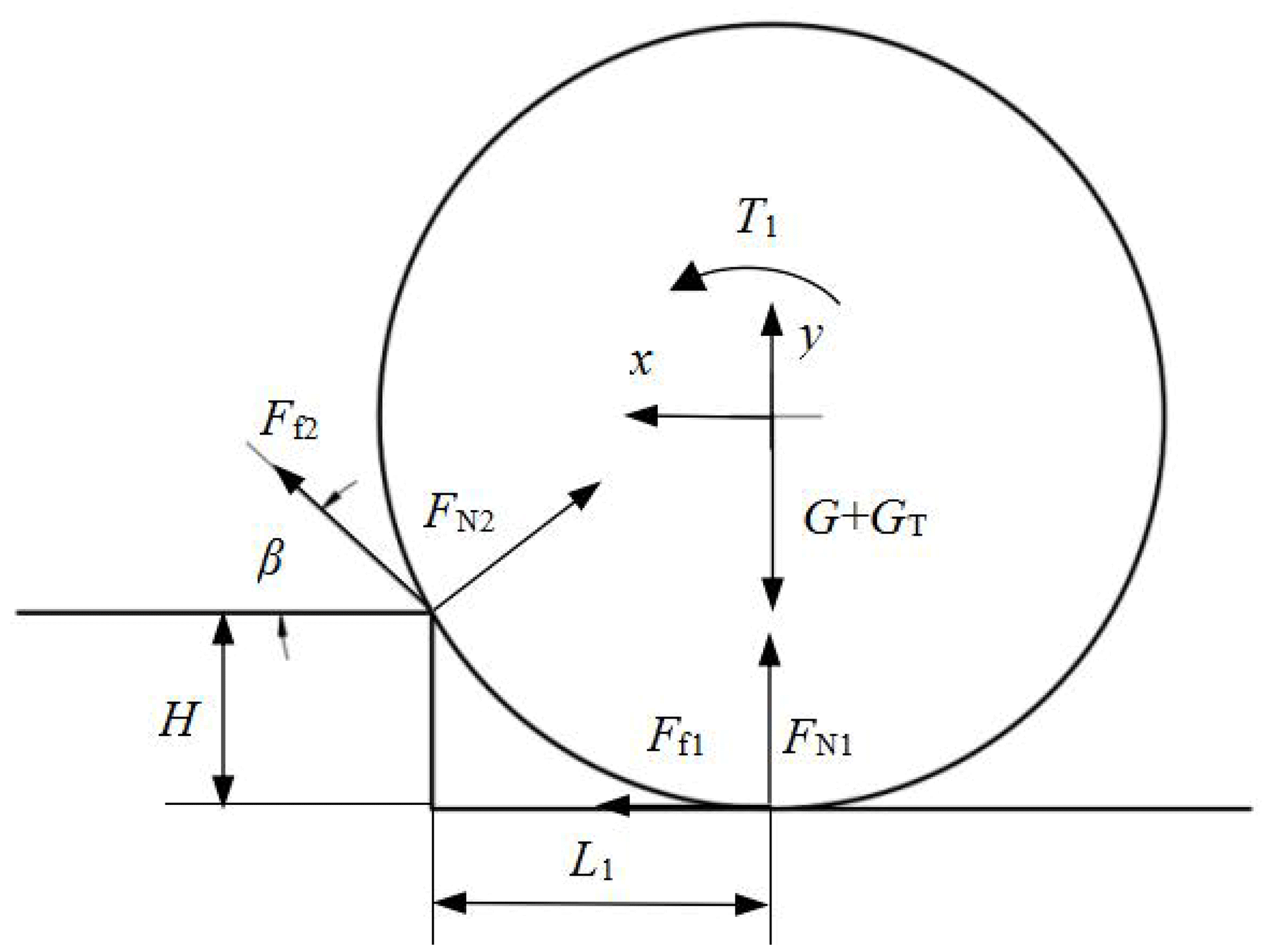
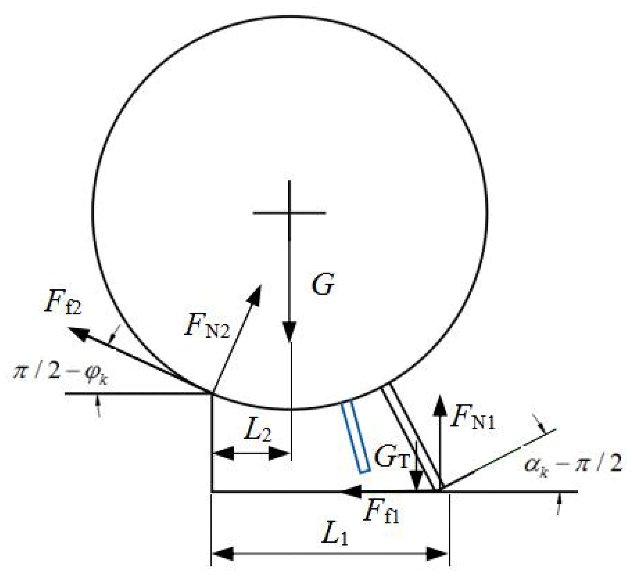
Firstly, the obstacle-surmounting dynamic model of the mechanism in rolling mode is established. Taking the overall system of the mechanism as the research object, the coordinate system is established at the center of the rolling wheel. The force on the mechanism is shown in Fig. 8. Assuming is the acceleration in the x, y direction and angular acceleration of the centroid of the main body, the equations of the force and moment are as follows:
where T1 is driving torque of rolling wheel, FN1 and FN2 are support forces of the ground and steps acting on the rolling wheel, Ff1, Ff2 is frictional force of the ground and steps acting on the rolling wheel, and β is the inclination angle between body and step, L1=Rsin α, .
Assuming ψ is the internal friction angle, the conditions that the mechanism does not slip at the contact point are as follows:
In addition, in order to ensure that the mechanism can climb the steps, the following conditions need to be met: ; ; . Therefore, the driving torque of the roller can be obtained as follows:
where .
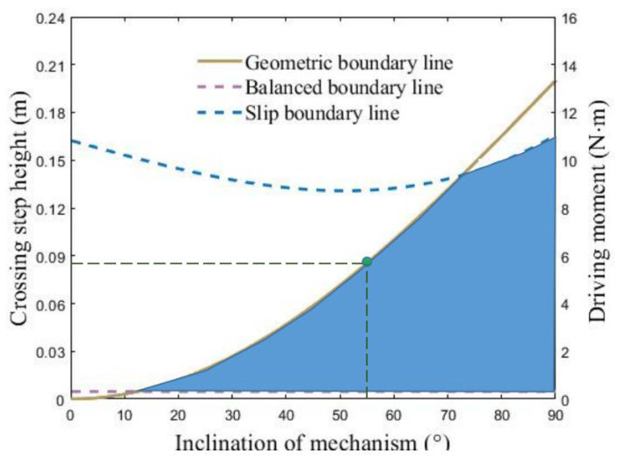
According to the geometric relationship in Fig. 8, the height range of the mechanism that can climb steps is . Let ψ=35∘, μ=0.1. The stable boundary line when rolling over the steps is shown in Fig. 9. It is shown that when the inclination angle of the mechanism increases, the height of the rolling climbing step increases, and the driving torque of the wheels also increases. According to the constraint condition that no slip occurs, the maximum inclination of the mechanism can be obtained as 54.28∘, thus the maximum climbing height of roll-over mode can be obtained as 87.36 mm.
Secondly, dynamic model of obstacle-crossing mode using support legs is established. The force on the mechanism is shown in Fig. 10. According to the geometric relationship, it can be obtained that the height range of support leg climbing steps is as follows:
The equations of the force and moment are as follows:
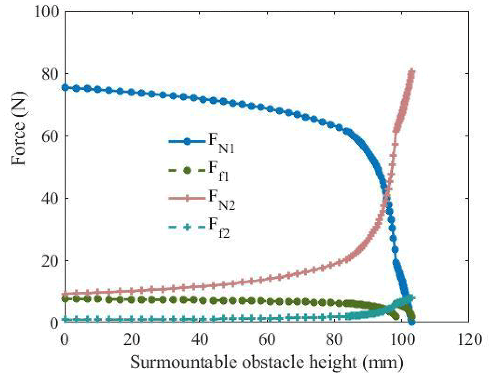
Let the height of the step be H=100 mm, the variation of force on the mechanism during climbing is shown in Fig. 11. It is shown that support force of the ground on the leg decreases with the increase of climbing height. When the climbing height is greater than 80 mm, the supporting force drops sharply. However, the supporting force of the steps on the main body increases with the increase of climbing height. When support leg 1 is switched to support leg 2, the supporting force and frictional force gradually increases or decreases. When support leg 2 is switched to support leg 3, the supporting force and frictional force change abruptly.
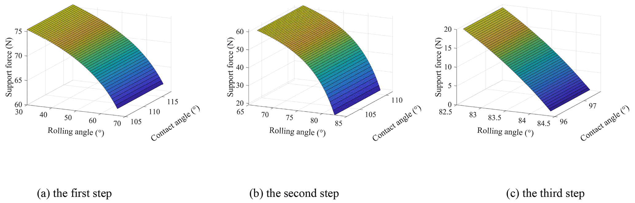
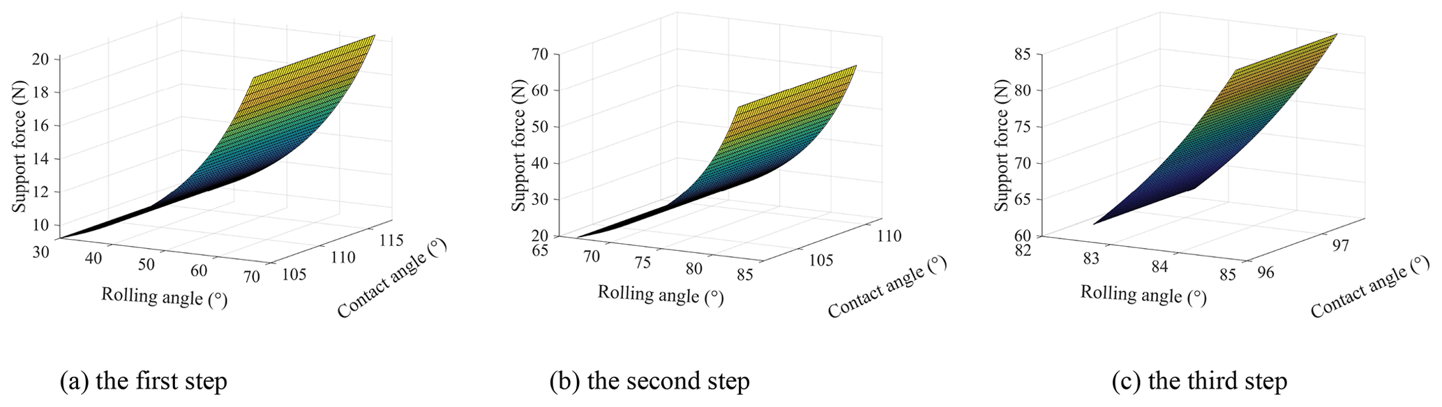
The supporting force of the ground on the leg changes with the rolling angle and contact angle, as shown in Fig. 12. It is shown that for the same support leg, the support force decreases with the increase of the rolling angle of the main body, while the change of the contact angle has little effect on the support force. When the rolling angle is 84.3∘, the support force on the leg is close to 0, and the wheel–leg deformation mechanism turns over the step. The supporting force of the step on the main body varies with the rolling angle and contact angle, as shown in Fig. 13. It is shown that the support force of the step increases with the increase of the rolling angle of the main body, and when the rolling angle is greater than 70∘, the support force increases sharply.

Let driving torque , the driving torque changes with the rolling angle and contact angle, as shown in Fig. 14. It is shown that the driving torque decreases with the increase of the rolling angle of the main body. That is to say, when the wheel–leg deformation mechanism climbs over the steps, the driving torque required is gradually reduced, and finally the climbing can be completed with the help of gravity.
3.3 Analysis of tipping stability during obstacle crossing
The wheel–leg deformation mechanism is often disturbed by external forces, environment, and other external factors when walking over obstacles, and may overturn. Therefore, the stability cone method is used to comprehensively evaluate the static and dynamic stability of the side line tipping and corner tipping of the wheel–leg deformation mechanism, in order to ensure the normal operation of the mechanism. The centroid P0 of the fuselage is taken as the apex of the stability cone, and the contact points Pi (i=1, … 3) between the deformation mechanism and the obstacle and the ground are regarded as the corners of the stabilizing cone. The coordinate system is established on the stable cone, take P0 as the origin, the vertical direction is the z axis, and the direction of mechanism movement is the x axis. The y axis is gotten by the right-hand rule. The stability cone model is shown in Fig. 15.

Assuming the vectors of contact points between the left and right rolling wheels and the obstacle are P1 and P3, and the contact points between the support leg and the ground are P2. The normal vector li of the tipping edge line ai is as follows:
where I is identity matrix.
In the process of obstacle crossing, it is assumed that the total external force received by the mechanism is Fr, and the total external moment received by the mass center of the main body is τr. The equivalent force of the total external force Fri, and the total external moment τri acting on the tipping edge line i is as follows:
When the wheel–leg deformation mechanism is under the action of equal force, the tipping angle of the sideline ai is defined as the angle γi, which is the angle between the equal force and the normal li. The tipping angle of the stable cone corner is defined as the angle ϕi, which is the angle between the equal force and Pi. The angle γi and the angle ϕi can be obtained by the following formula:
where , when , σi=1. Otherwise, .
Considering the global stability of the system, let , then the minimum stability angle of the whole system is
Comprehensively considering the side line tipping angle and corner tipping angle, the stability index of the wheel–leg deformation mechanism is
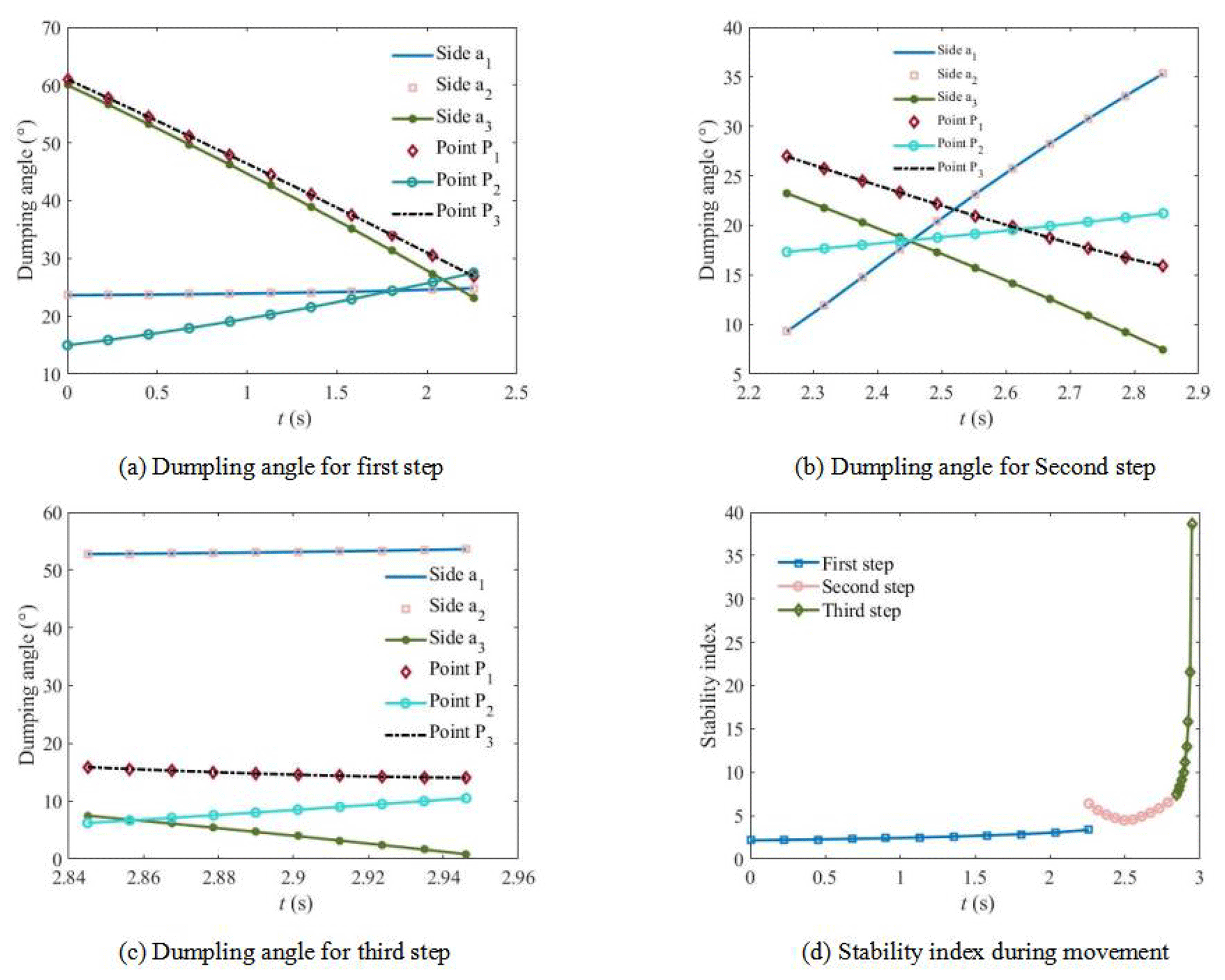
Without interference, the stability analysis results of the wheel–leg deformation mechanism are shown in Fig. 16. When support leg 1 works, the change of side line tipping angle and corner tipping angle with time is shown in Fig. 16a. It is shown that because of the symmetry of the structure, the tipping angles of the sidelines a1 and a2 are the same, and the corner P1 and P3 have the same tipping angle. The tipping angles of side line a3, corner P1, and P3 decrease with time. However, the tipping angle of the corner P3 increases with time. When support leg 2 works, the change of side line tipping angle and corner tipping angle with time is shown in Fig. 16b. It is shown that the tipping angle of sidelines a1 and a2 increases with time. The change of the tipping angle of the other sidelines and corners with time is similar to that of the support leg 1. When support leg 3 works, the change of side line tipping angle and corner tipping angle with time is shown in Fig. 16c. It is shown that the tipping angle of side line a3 gradually approaches 0∘ with the increase of time, and the tipping angles of other side lines and corners change little with time. The change of stability index with time during the climbing process of the wheel–leg deformation mechanism is shown in Fig. 16d. It is shown that when support leg 1 and support leg 2 work, the system is relatively stable. When the support leg 3 works, the system becomes extremely unstable. When t=2.95 s, the whole mechanism overturns along the side line a3; that is, the whole mechanism crosses the step.
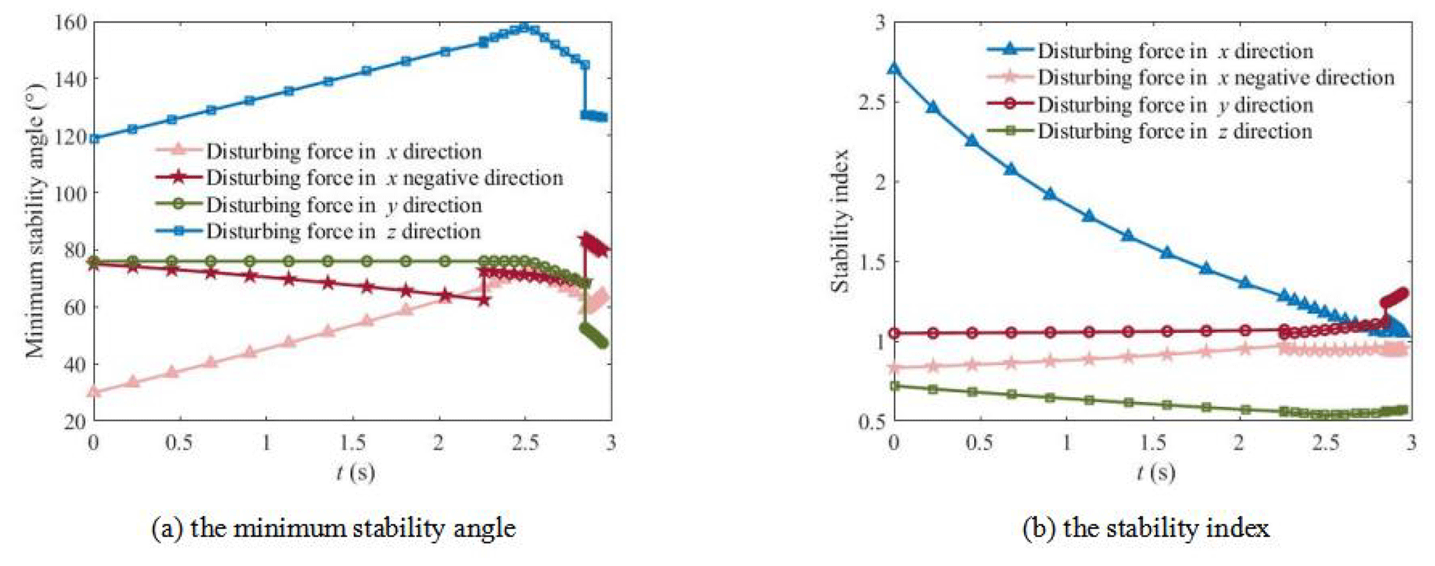
To test the anti-interference ability of the wheel–leg deformation mechanism, the interference force is applied in the positive and negative directions along the x axis, the positive direction of the y axis, and the positive direction of the z axis, respectively. Note that because the roller is symmetrical to the center of mass, the interference effect in the positive and negative directions of y axis is the same, so only the interference force in the positive direction of y axis is discussed. The interference effect in the negative direction of the z axis is the same as that of gravity, and the overturning stability is similar to that without interference. Therefore, only the interference force in the positive direction of the z axis is discussed. Let , , and , the change of the minimum stability angle of the system with time is shown in Fig. 17a. It is shown that the minimum stability angle will jump when the support legs alternate. When the disturbing force is applied along the positive direction of the x axis and the positive direction of the z axis, the minimum stability angle will increase with time. When the disturbing force is applied along the negative direction of the x axis and the positive direction of the y axis, the minimum stability angle will decrease with time. The change of the stability index of the system with time is shown in Fig. 17b. It is shown that when the disturbing force is applied along the positive direction of the x axis, the stability index will decrease with time. Other disturbing forces have little change with time. The existence of interference force has little influence on the stability of the system. This shows that the mechanism has good anti-interference ability.
In this paper, a wheel–leg deformation mechanism suitable for a complex road environment is designed. The switching principle of the wheels and legs, gait planning for leg-type obstacle-crossing, obstacle-climbing performance, and rollover stability are discussed. Combining theoretical analysis and dynamics simulation, the rationality of the wheel–leg deformation mechanism design and the feasibility of leg-type obstacle-crossing walking are verified. The main conclusions are as follows:
-
A new type of wheel–leg deformation mechanism based on gear transmission is proposed. The mechanism has high maneuverability of wheel rolling and high adaptability of leg obstacle climbing. When the road surface is flat, the roller mode is used to achieve fast forward speed. When encountering unstructured terrain such as steps and gullies, the support leg mode can be switched by the electromagnetic clutch to complete obstacle crossing.
-
The gait of support legs is planned and the kinematics characteristics of the mechanism are studied. It is shown that the wheel–leg deformation mechanism can surmount obstacles through alternate support of contact feet. The alternation of the support legs does not affect the smooth climbing of the mechanism, but will cause the step change of the angular velocity of the centroid. Different support legs have different initial contact angles which increase with the extension of the leg.
-
The obstacle-surmounting performance of roll-over mode and obstacle-crossing mode using support legs are analyzed. For roll-over mode, when the inclination angle of the mechanism increases, the height of the rolling climbing step increases and the driving torque of the wheels also increases. For obstacle-crossing mode using support legs, support force of the ground on the leg decreases with the increase of climbing height, while support force of the step on the main body increases with the increase of climbing height. The rolling angle of the main body has a greater impact on the support force and driving torque, while the contact angle between the legs and the ground has a small impact.
-
The stability cone method is used to comprehensively evaluate the static and dynamic stability of the wheel–leg deformation mechanism. It is shown that the closer the support leg is to the step, the smaller the stability angle of the mechanism along the side line a3 without external force interference so that the whole mechanism crosses the step. The analysis on the anti-interference ability of the mechanism shows that the existence of interference force has little influence on the stability of the system. The mechanism has good anti-interference ability.
The data that support the findings of this study are available from the corresponding author upon reasonable request.
MZ conceptualized the study, wrote the original draft of the paper, and reviewed and edited the paper. YS was responsible for data curation and validation.
The contact author has declared that neither of the authors has any competing interests.
Publisher's note: Copernicus Publications remains neutral with regard to jurisdictional claims in published maps and institutional affiliations.
This research has been supported by the Open Project of Anhui Province Key Laboratory of Special and Heavy Load Robot (grant no. TZJQR004-2022).
This paper was edited by Daniel Condurache and reviewed by two anonymous referees.
Aoki, T., Asami, K., Ito, S., and Waki, S.: Development of quadruped walking robot with spherical shell: improvement of climbing over a step, Robomech. J., 7, 22, https://doi.org/10.1186/s40648-020-00170-5, 2020.
Baishya, N. J., Bhattacharya, B., Ogai, H., and Tatsumi, K.: Design of an anti-slip mechanism for wheels of step climbing robots, Actuators, 10, 259, https://doi.org/10.3390/act10100259, 2021.
Chen, H., Wang, T., Ho, K., Ko, C., Lin, P., and Lin, P.: Development of a novel leg-wheel module with fast transformation and leaping capability, Mech. Mach. Theory, 163, 104348, https://doi.org/10.1016/j.mechmachtheory.2021.104348, 2021.
Cong, P., Liu, J., and Feng, X.: Mechanism design and simulation analysis of deformable wheeled Mobile Robot, Journal of Mechanical Transmission, 45, 76–83, https://doi.org/10.16578/j.issn.1004.2539.2021.08.011, 2021.
Ding, D. and Zhang, S.: Design and research of a variable-diameter wheel-legged obstacle overcoming robot, Mechanical Science and Technology for Aerospace Engineering, 1–8, https://doi.org/10.13433/j.cnki.1003-8728.20220014, online first, 2022.
Kim, Y., Kim, J., Kim, H. S., and Seo, T.: Curved-spoke tri-wheel mechanism for fast stair-climbing, IEEE Access, 7, 173766–173773, https://doi.org/10.1109/ACCESS.2019.2956163, 2019.
Kim, Y., Lee, Y., Lee, S., Kim, J., and Kim, H. S. T: Step: A new mobile platform with 2-DOF transformable wheels for service robots, IEEE-ASME T. Mech., 25, 1859–1868, https://doi.org/10.1109/TMECH.2020.2992280, 2020.
Lee, K., Ryu, S., Kim, C., and Seo, T.: A compact and agile angled-spoke wheel-based mobile robot for uneven and granular terrains, IEEE Robotics and Automation Letters, 7, 1620–1626, https://doi.org/10.1109/LRA.2022.3141204, 2022.
Lin, H. S., Lin, Y. M., and Lin, P. C.: Slip-model-based dynamic motion transition between different fixed points in one stride in a leg-wheel transformable robot, 2018 IEEE/RSJ International Conference on Intelligent Robots and Systems (IROS), 1–5 October 2018, Madrid, Spain, IEEE, https://doi.org/10.1109/IROS.2018.8594364, 2018.
Lv, Z.: Study on obstacle-surmounting performance of wheel type deformation wheel, Modern Manufacturing Engineering, 2020, 82–85, https://doi.org/10.16731/j.cnki.1671-3133.2020.06.014, 2020.
Mertyüz, R., Tanyldz, A. K., Tasar, B., Tatar, A. B., and Yakut, O.: FUHAR: A transformable wheel-legged hybrid mobile robot, Robot. Auton. Syst., 133, 103627, https://doi.org/10.1016/j.robot.2020.103627, 2020.
Ning, M., Xue, B., Ma, Z., Zhu, C., Liu, Z., Zhang, C., Wang, Y., and Zhang, Q.: Design, analysis, and experiment for rescue robot with wheel-legged structure, Math. Probl. Eng., 2017, 1–16, https://doi.org/10.1155/2017/5719381, 2017.
Ryu, S., Lee, Y., and Seo, T. W.: Shape-morphing wheel mechanism for step climbing in high speed locomotion, IEEE Robotics and Automation Letters, 5, 1977–1982, https://doi.org/10.1109/LRA.2020.2970977, 2020.
Sanchez, S. and Bhounsule, P. A.: Design, modeling, and control of a differential drive rimless wheel that can move straight and turn, Automation, 2, 98–115, https://doi.org/10.3390/automation2030006, 2021.
Song, Y., Hao, C., Yue, W., Sun, T., Lian, B., and Yang, Z.: Kinematic analysis and design of a novel transformable wheeled-legged mobile robot, Journal of Tianjin University (Science and Technology), 55, 111–121, 2022.
Sun, Y., Dou, G., Duan, W., Chen, X., Zheng, J., Xin, L., and Bai, L.: Involute-arc-leg for multi-legged robot: high stability and low energy consumption, Mech. Mach. Theory, 170, 104701, https://doi.org/10.1016/j.mechmachtheory.2021.104701, 2022.
Tan, N., Sun, Z., Mohan, R. E., Brahmananthan, N., Venkataraman, S., Sosa, R., and Wood, K.: A system-of-systems bio-inspired design process: conceptual design and physical prototype of a reconfigurable robot capable of multi-modal locomotion, Front. Neurorobotics, 13, 78, https://doi.org/10.3389/fnbot.2019.00078, 2019.
Teng, W.: Design of wheel leg deformation robot for disaster rescue, Value Engineering, 39, 211–214, 2020.
Tholapu, S., Sudheer, A. P., and Joy, M. L.: Kinematic modelling and structural analysis of a spherical robot: BALL-E, IOP Conf. Ser.-Mat. Sci., 1132, 12034, https://doi.org/10.1088/1757-899X/1132/1/012034, 2021.
Vina, A. and Barrientos, A.: C-legged hexapod robot design guidelines based on energy analysis, Appl. Sci., 11, 2513, https://doi.org/10.3390/app11062513, 2021.
Wang, T. H. and Lin, P. C.: A reduced-order-model-based motion selection strategy in a leg-wheel transformable robot, IEEE-ASME T. Mech., 27, 3315–3321, https://doi.org/10.1109/TMECH.2021.3126606, 2021.
Xie, Q., Liu, S., and Ma, X.: Design of a novel inchworm in-pipe robot based on cam-linkage mechanism, Adv. Mech. Eng., 13, 1069523785, https://doi.org/10.1177/16878140211045193, 2021.
Xu, Q., Xu, H., Xiong, K., Zhou, Q., and Guo, W.: Design and analysis of a bi-directional transformable wheel robot trimode, 2021 IEEE/RSJ International Conference on Intelligent Robots and Systems (IROS), 27 September–1 October 2021, Prague, Czech Republic, IEEE, https://doi.org/10.1109/IROS51168.2021.9636421, 2021.
Yamamoto, K. and Aoki, T.: Development of novel mobile robot with semicircular wheels, Robomech. J., 7, 32, https://doi.org/10.1186/s40648-020-00180-3, 2020.
Yuan, J., Wang, Z., Zhang, Z., Xing, Y., and Ji, A.: Mechanism design of a transformable crawling robot and feasibility analysis for the unstructured environment, Actuators, 11, 60, https://doi.org/10.3390/act11020060, 2022.
Zhai, J., Wu, F., Wei, X., and Luo, H.: Design and study of walking mechanism of deformable wheel-legged robot, Journal of Mechanical Transmission, 45, 157–161, https://doi.org/10.16578/j.issn.1004.2539.2021.01.026, 2021.
Zhang, L.: Research on wheel-legged hybrid mobile robot based on eccentric paddle-wheeled mechanism, Master thesis, Shanghai University, https://doi.org/10.27300/d.cnki.gshau.2021.000372, 2021.
Zhang, L. and Sun, Y.: Design, Modeling and performance evaluation of mobile robot based on eccentric paddle mechanism, J. Phys. Conf. Ser., 1802, 042018, https://doi.org/10.1088/1742-6596/1802/4/042018, 2021.
Zhang, S., Yao, J. T., Wang, Y. B., Liu, Z. S., Xu, Y. D., and Zhao, Y. S.: Design and motion analysis of reconfigurable wheel-legged mobile robot, Defence Technology, 18, 1023–1040, https://doi.org/10.1117/12.2625561, 2021.
Zeng, W., Xu, G., Jiang, H., and Gao, F.: Development of a novel variable-diameter wheel, Appl. Sci., 9, 4631, https://doi.org/10.3390/app9214631, 2019.