the Creative Commons Attribution 4.0 License.
the Creative Commons Attribution 4.0 License.
 | 04 Nov 2022
Surface modification and tooth contact analysis of variable hyperbolic circular-arc-tooth-trace cylindrical gears
Yongping Liu
Dengqiu Ma
To improve the bearing capacity and provide the mathematical model basis for vibration and noise reduction of the variable hyperbolic circular-arc-tooth-trace (VH-CATT) cylindrical gear, the tooth surface modification design method based on the parabolic forming blade and cutter inclination was proposed. The geometric design of inclined cutter was completed. The modified tooth surface equation was deduced, and the influence of modification parameters on tooth surface curvature characteristics was analysed further. The tooth contact analysis (TCA) was established, and the influence of modification parameters on the elliptical contact area was analysed. Research shows that the parabolic coefficient a and the parabolic vertex position u0 have effects on the main curvature of concave–convex tooth surface, both the tooth profile and the tooth line direction, but the cutter inclination angle only has influence on the curvature of the tooth line direction, and the influence is larger. The cutter inclination angle γ, parabola coefficient a, and parabolic vertex position u0 have certain influences on the elliptical contact area. The cutter inclination angle γ is the most important modification parameter to improve the bearing capacity, but the excessive cutter inclination angle will cause bridge contact, the value range cutter inclination γ can be determined based on the tooth line radius. The research results provide a technical basis for improving the bearing capacity of the VH-CATT cylindrical gear and optimising the design.
- Article
(23054 KB) - Full-text XML
- BibTeX
- EndNote


Tooth surface modification technology can improve the pressure distribution of tooth surface, reduce the meshing-in and meshing-out impact, and improve the stability of system. It is an important technical means to reduce vibration and noise (Guo et al., 2021; Peng et al., 2020). For example, Nie et al. (2019) proposed a kind of Ease-off topology modification method for hypoid gears to improve meshing performance, the load tooth contact analysis (TCA) results indicate that the modified tooth flank contact stress distribution is improved. Jia et al. (2021) proposed a tooth modification design method of vibration reduction for involute helical gears considering the measured load spectrum, and the results show that the amplitude of loaded transmission error and the meshing-in impact force are effectively reduced after optimum tooth modification. Jiang et al. (2021) proposed a design and analysis method of tooth surface dynamic anti-wear modification to improve the contact performance.
The variable hyperbolic circular-arc-tooth-trace (VH-CATT) cylindrical gear is a new gear transmission. The tooth direction line of the VH-CATT cylindrical gear is an arc line, the tooth profile of the middle cross section is involute, and the other sections are hyperbolic (Ma et al., 2019). When the tooth surfaces are loaded, the contact area generally appears as an ellipse (Ma et al., 2021a). At present, the VH-CATT cylindrical gear has rich achievements about the meshing principle, 3D modelling and contact performances, processing and manufacturing, product application, etc. For example, Tseng and Tsay (2005), Zhao et al. (2016), and Song et al. (2010) deduced the tooth surface equation based on the gear-meshing principle, respectively. Li Hou realised the machining simulation of the VH-CATT cylindrical gears based on UG (Unigraphics NX), but there are machining marks on the tooth surface (Wang et al., 2012), and the 3D accurate model of the VH-CATT cylindrical gears was established according to the mathematical model (Zhao et al., 2016). Ma et al. (2018, 2021b) proposed the meshing contact impact hypothesis of the VH-CATT cylindrical gear based on the contact dynamics theory and gear transmission physical model; the gear mesh contact impact model was set up further to obtain the VH-CATT cylindrical gear's meshing contact impact properties. Wei et al. (2020) established the contact stress calculation model of the VH-CATT cylindrical gear based on the Hertz contact theory, which provided a reference for the contact stress calculation of the VH-CATT cylindrical gear. In addition, Fuentes et al. (2014), Fuentes-Aznar et al. (2017), Zhang and Xie (2016), and Chen and Lo (2015) established a 3D model of the VH-CATT cylindrical gear to study the contact performances by the finite element method compared with the spur gear and helical gear.
However, there are still some restricting factors in the industrial application of the VH-CATT cylindrical gear. The contact area of the VH-CATT cylindrical gear is the elliptical area on load. However, the ratio of the elliptical long axis to the gear width is small, and the tooth width is not fully used for the gear contact load. At the same time, due to the manufacturing errors, installation errors, and bearing contact deformation, the meshing-in and meshing-out impact of the unmodified VH-CATT cylindrical gear is larger. Because of the lack of tooth surface modification design technology, the optimisation design of tooth surface, system vibration, and noise reduction, improvement of bearing capacity cannot be completed.
Therefore, the tooth surface modification design method of the VH-CATT cylindrical gear was proposed. The tooth surface equation of the modified VH-CATT cylindrical gear was deduced based on the gear-machining development principle and the influence law of modification parameters on the main curvature of the tooth surface contact point was analysed. The TCA model of the VH-CATT cylindrical gear was established and the influence of modification parameters on elliptical contact area was analysed. Considering design efficiency and machining economy, only the tooth surface of the driven gear was modified in TCA. The research content provides a technical basis for improving the bearing capacity of the VH-CATT cylindrical gear and optimising the design.
2.1 Cutter design of gear profile modification
To effectively reduce the meshing-in and meshing-out impact of the gear system, the parabolic modification curve is adopted for the tooth profile forming cutter blade, shown in Fig. 1. The second-, fourth- or higher-order parabola curve can be obtained by changing n (). In Fig. 1a, Δt is the addendum modification and Δr is the root modification; Odp is the parabola vertex position of the parabolic modification curve; u0 is the distance between the parabola vertex position and the pitch line of the unmodified straight blade. Figure 1b is the sectional view of the shaping blade. The expression of the shaping blade curve in the coordinate system OdpXdpYdpZdp can be written in the following way:
where a is the parabolic coefficient, the outer blade is positive and the inner blade is negative.
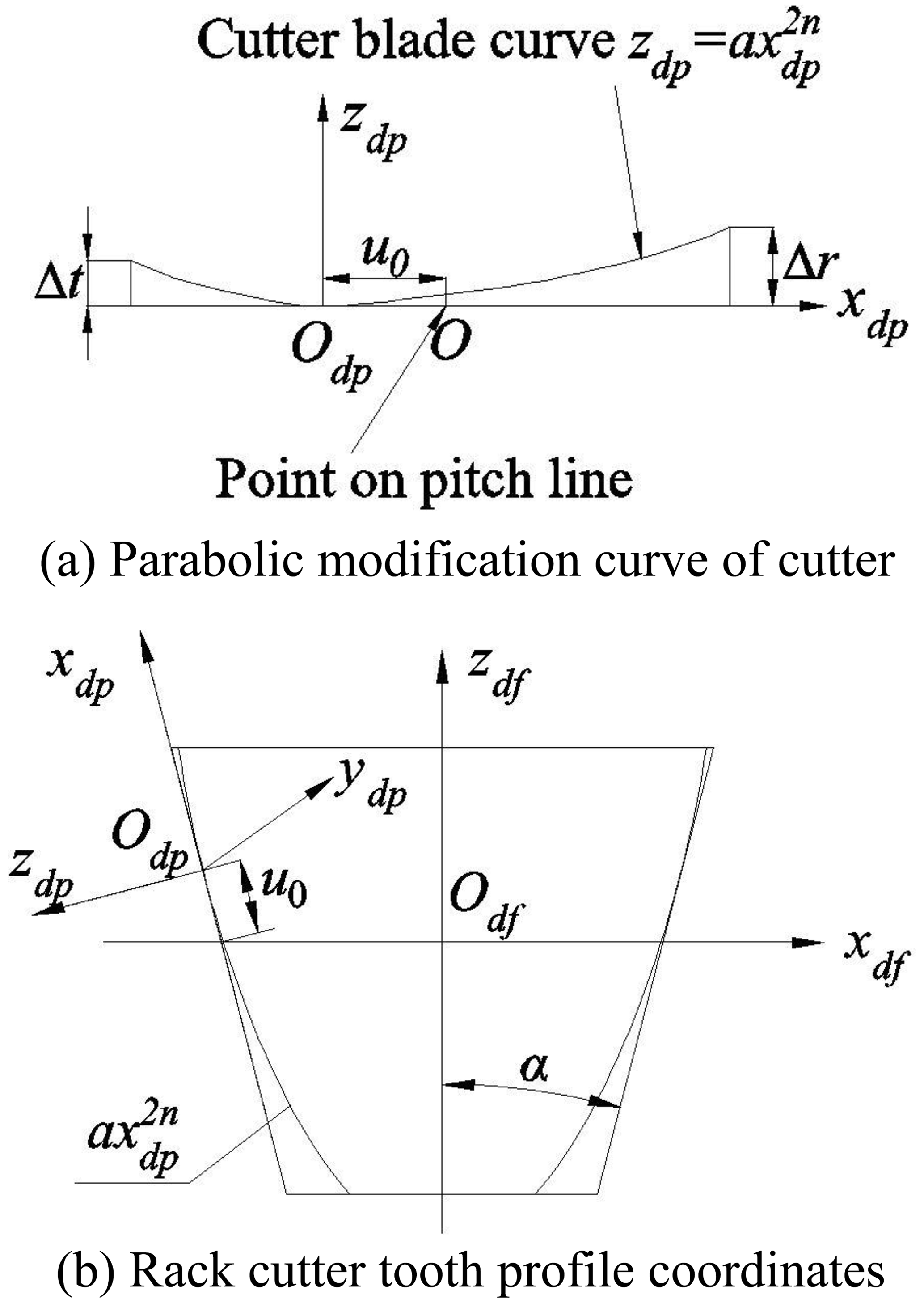
The parabolic blade profile in the coordinate system OdpXdpYdpZdp can be written as follows:
where the upper part of the symbol is the outer blade, and the lower part of the symbol is the inner blade.
2.2 Cutter head design of tooth line modification
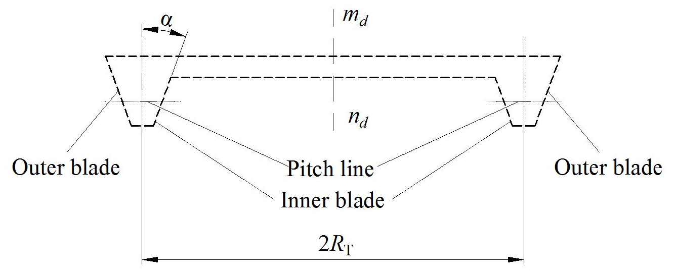
To increase the length of the contact line along the tooth line direction, a modification method of the VH-CATT cylindrical gear along the tooth line direction by the cutter-inclined milling is proposed. Figure 2 is the schematic diagram of the conventional milling cutter head for the VH-CATT cylindrical gear. The cutter head rotates around the axis mdnd, α is the included angle between the inner blade or the outer blade and the mdnd axis, the inner blade's pitch line radius is equal to , and the outer blade's pitch line radius is equal to . Figure 3 is the schematic diagram of the cutter-inclined milling for the VH-CATT cylindrical gear.
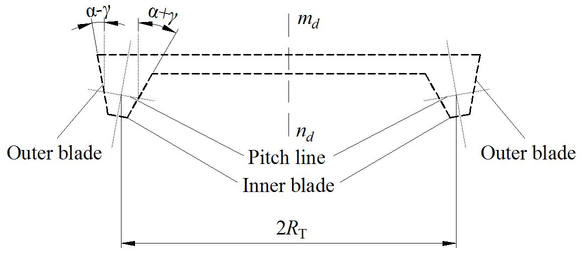
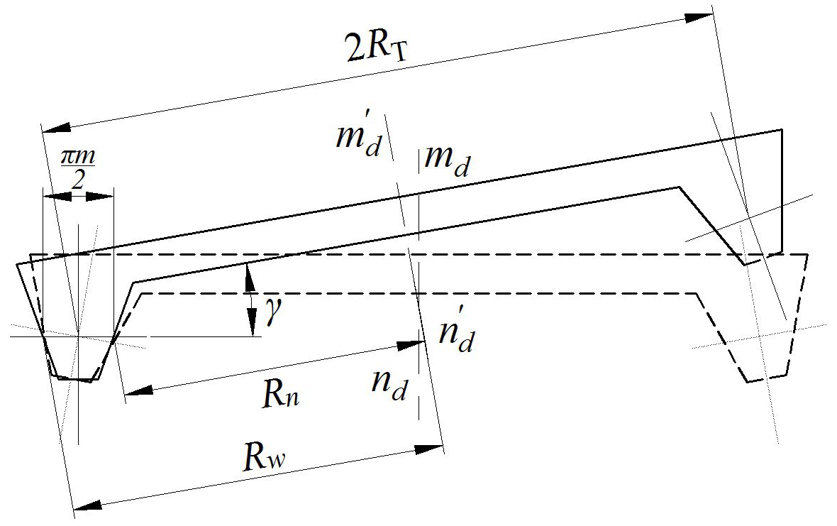
To ensure that the pitch line of the cutter blade is tangent to the pitch circle of the gear blank, when the inclined tool is installed as standard, the cutter head is installed at an inclination angle, shown in Fig. 4. At this time, the cutter head rotates around the axis . The direction of the cutter head's translation reciprocating motion is horizontal, and the included angle between the translation reciprocating motion and the cutter head rotating axis is , the included angle between the cutter blade and the axis is Eq. (3), the cone-apex angle of the inner-blade revolving surface is equal to α+γ, the cone-apex angle of the outer-blade revolving surface is equal to α−γ, RT is the distance from the tooth thickness point on the pitch line to rotation axis , Eq. (4) is the gyration radius of the inner and outer cutter blades. In Eqs. (3) and (4), the benchmark n is inner blade and w is outer blade:
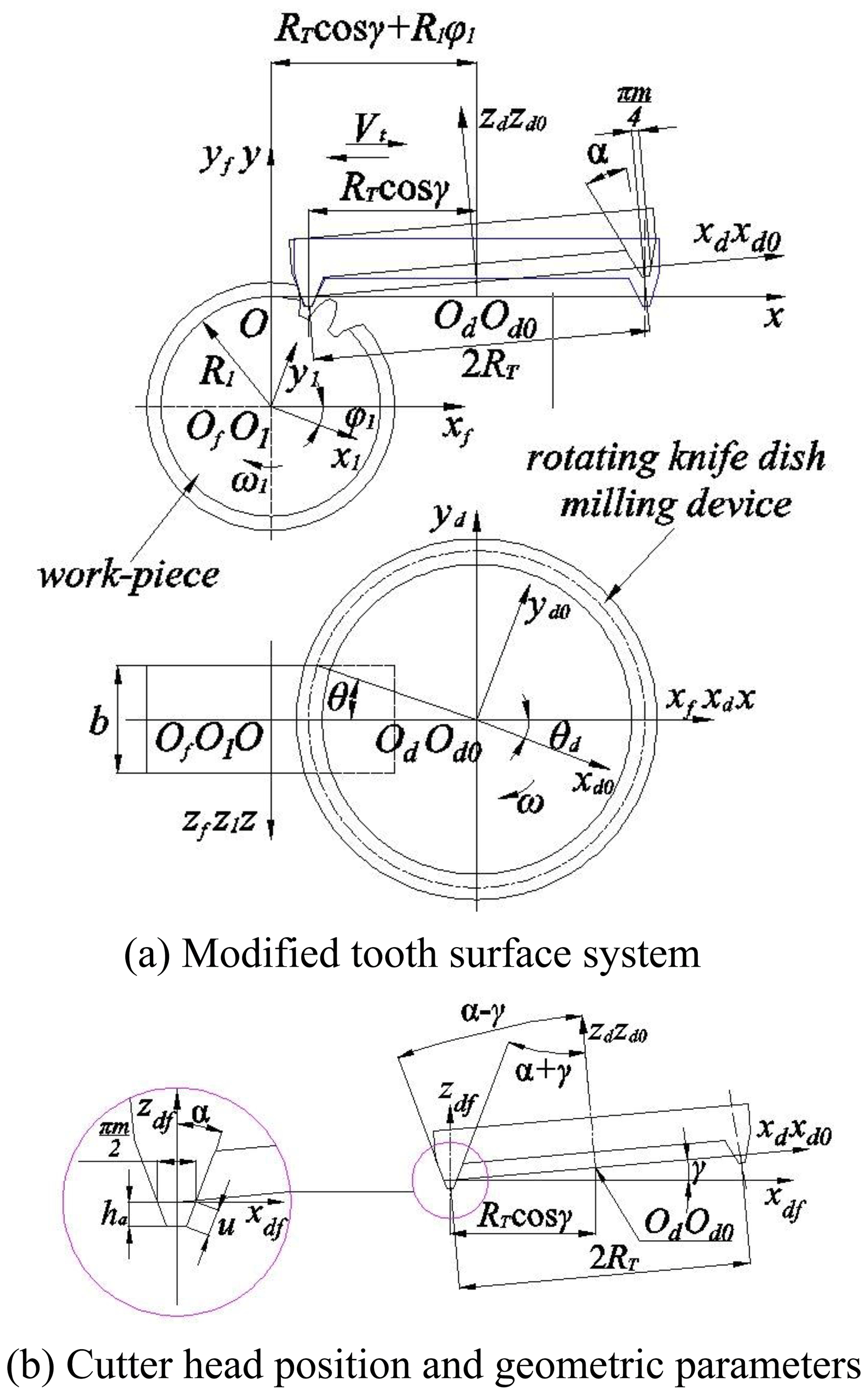
To derive the modified mathematical model of the VH-CATT cylindrical gear, the coordinate transformation system of the modified tooth surface is established, shown in Fig. 5. Figure 5b is the cutter head position and geometric parameters. The dynamic coordinate system of the gear blank is O1X1Y1Z1; Od0Xd0Yd0Zd0 is the dynamic coordinate system of the cutter; OdXdYdZd is the static coordinate system of the cutter; OfXfYfZf is the static coordinate system of the gear blank; and OXYZ is the intermediate coordinate system. The pitch circle radius is R1; m is the gear module; b is the gear width; ω is the angular velocity of the cutter head; ω1 is the gear blank's angular velocity; θd is the spreading angle of cutter head; and φ1 is the involute angle.
According to Eq. (2) and the coordinate transformation relationship shown in Fig. 5, the expression of the inclined cutter in OdXdYdZd can be written as follows:
According to Litvin (2008), the normal vector and relative speed at the meshing point of the modified tooth surface are Eqs. (6) and (7), respectively:
where ,
According to Litvin (2008), the product of relative speed and normal vector is zero:
Equation (9) is simplified by Eq. (8) and u is the solution of Eq. (9):
where
The MATLAB numerical calculation shows that there are virtual roots and 1 real root in Eq. (9). According to the structural characteristics and actual physical significance of the VH-CATT cylindrical gear, the real root is taken as u value. To get the modified tooth surface mathematical model of the VH-CATT cylindrical gear, it is necessary to transform the equation of inclined cutter surface in OdXdYdZd into O1X1Y1Z1. According to Fig. 5, the transformation matrix A1d from OdXdYdZd to O1X1Y1Z1 is Eq. (14):
So, the modified tooth surface equation can be expressed as follows:
where n is an integer such as 1, 2, and 3, and corresponds to the second-, fourth-, and sixth-order parabolic modified tooth surface equations, respectively.
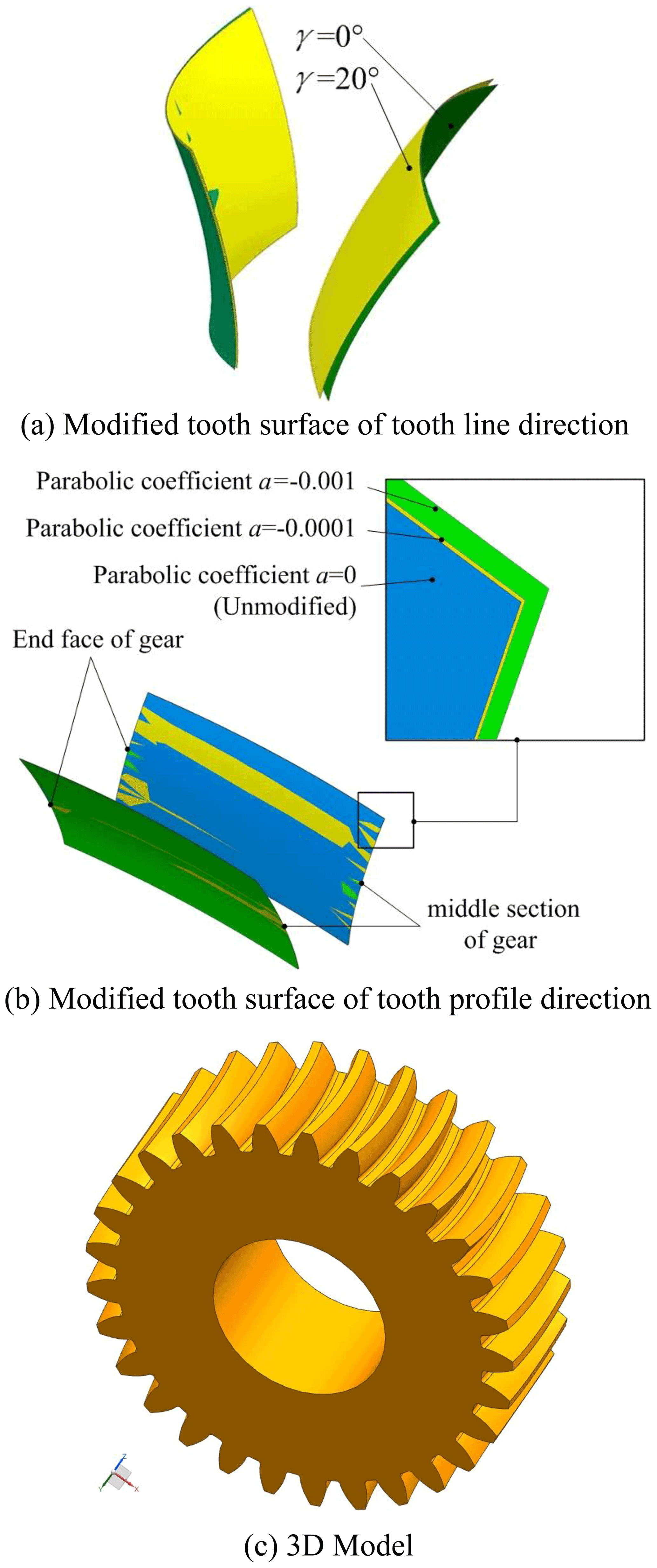
Figure 6 is the modified tooth surface. The important parameters are as follows: tooth number z=29, tooth width b=80 mm, pressure angle , modulus m=8 mm, tooth radius RT=200 mm. Figure 6a shows the comparison before and after modification of the tooth line direction. It can be seen that the cutter angle mainly affects the bending degree of the tooth. Figure 6b shows the comparison before and after the tooth profile modification. It can be seen that the tooth profile modification mainly changes the structural characteristics of tooth top and tooth root, a part of the material is cut off from the tooth root and tooth top, and the tooth thickness is reduced.
The curvature of the tooth surface is an important parameter which reflects the geometric characteristics of the tooth surface. The curvature characteristic analysis of the modified tooth surface plays an important role in the contact performance analysis. According to Ma et al. (2021a), the calculation expressions of the contact ellipse and principal curvature are Eqs. (16) and (17), respectively, and the meanings of parameters in the equations can be found in Ma et al. (2021a):
Taking the second-order parabolic profile modification tooth surface as the research object, the influence of the cutter inclination angle γ, parabolic coefficient a, and parabolic vertex position u0 on the curvature of the concave and convex tooth surfaces was analysed, shown in Figs. 7–12. According to Zhao et al. (2020), the involute angle value range of the concave tooth surface from tooth root to tooth top is −0.22 to 0.22, and the involute angle value range of the convex tooth surface from tooth top to tooth root is −0.22 to 0.22; tooth number z=29, pressure angle , modulus m=8 mm, tooth line radius RT=200 mm.
4.1 Influence of cutter inclination angle γ on the curvature
Figure 7 shows the influence of the cutter inclination angle γ on the main curvature along the tooth profile and tooth line direction of the modified concave tooth surface. Figure 8 shows the influence of the cutter inclination angle γ on the main curvature along the tooth profile and tooth line direction of the modified convex tooth surface. The cutter inclination angle γ is equal to 0, 5, 10, 15, 20∘, respectively. The parabolic coefficient a is equal to ±0.0005. The parabolic vertex position u0 is equal to 0 mm.

Figure 7Influence of cutter inclination angle γ on main curvature of modified concave tooth surface.
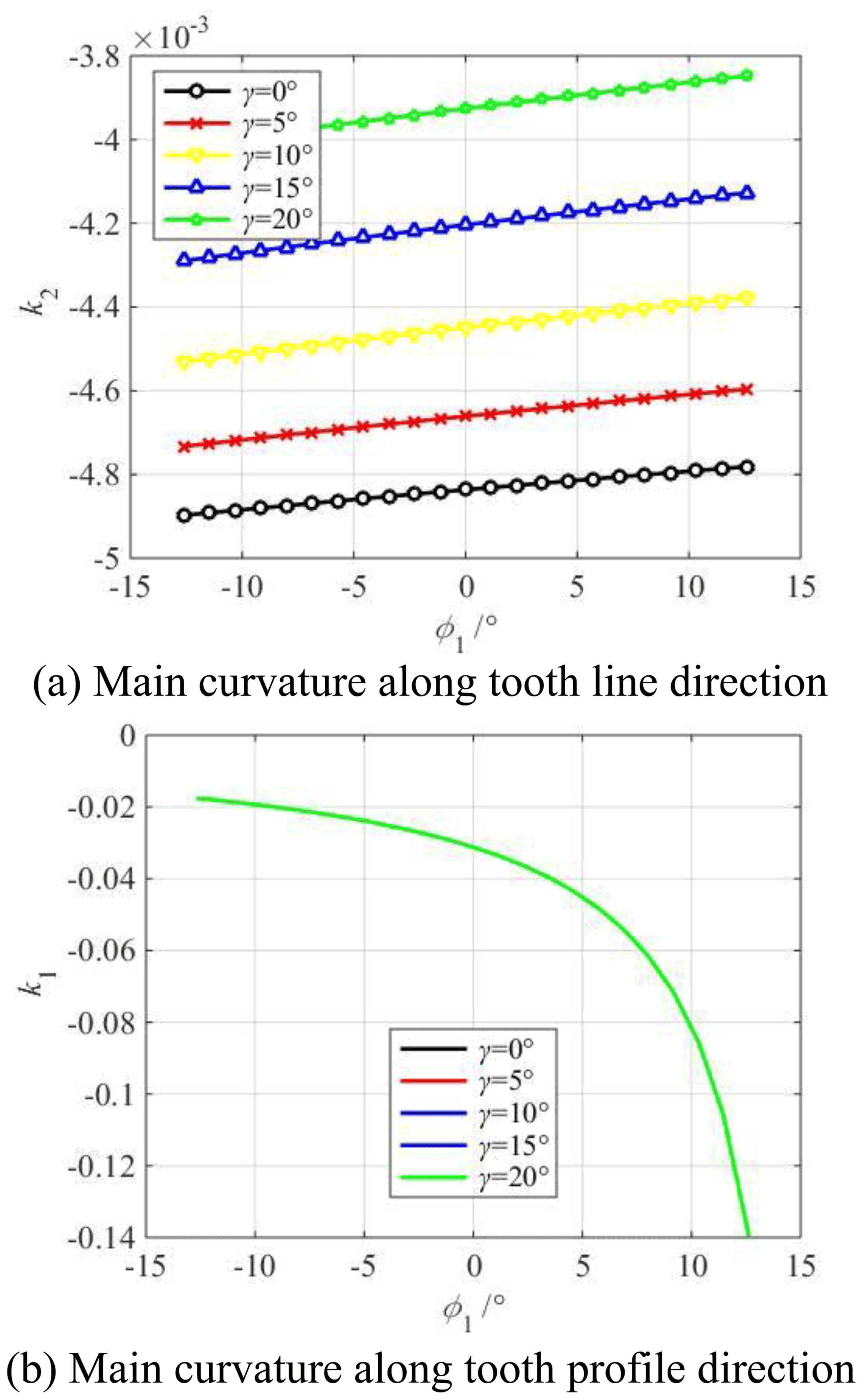
Figure 8Influence of cutter inclination angle γ on main curvature of modified convex tooth surface.
According to Figs. 7a and 8a, it is obvious that the main curvature along the tooth line direction of the concave tooth surface gradually decreases from the tooth root to the tooth top, and the main curvature along the tooth line direction of the convex tooth surface gradually increases from the tooth root to the tooth top. The reason for the increase or decrease in the main curvature is the following: the rotary surface of the concave tooth surface forming blade is an inverted cone, and the rotary surface of the convex tooth surface forming blade is a positive cone. At the same time, it can be seen that the main curvature along the tooth line direction of the concave tooth surface increases with the increase in the cutter inclination angle, and the main curvature along the tooth line direction of the convex tooth surface decreases with the increase in the cutter inclination angle. It indicates that the degree of the crescent bay increases, which has an important influence on the long axis of the contact ellipse.
According to Figs. 7b and 8b, the main curvature along the tooth profile direction gradually decreases from the tooth root to the tooth top. Theoretically, the curvature at the base circle is infinite. It can also be seen that the cutter inclination angle γ has no effect on the main curvature along the tooth profile direction regardless of the concave and convex tooth surfaces. The reason is the following: no matter how large the cutter inclination angle is, only the tooth line radius of the tooth surface forming is changed, but the change of the tooth line radius has no effect on the involute profile of the middle section.
4.2 Influence of parabolic coefficient a on the curvature
Figure 9 shows the influence of the parabolic coefficient a on the main curvature along the tooth profile and tooth line direction of the modified concave tooth surface. Figure 10 shows the influence of the parabolic coefficient a on the main curvature along the tooth profile and tooth line direction of the modified convex tooth surface. The parabolic coefficient a is equal to 0, ±0.0001, ±0.0005, ±0.001, respectively. The cutter inclination angle γ is equal to 0∘. The parabolic vertex position u0 is equal to 0 mm.

Figure 9Influence of parabolic coefficient a on main curvature of the modified concave tooth surface.

Figure 10Influence of parabolic coefficient a on main curvature of the modified convex tooth surface.
According to Figs. 9a and 10a, the tooth line direction's main curvature of the concave and convex tooth surfaces increases with the increase in the parabolic coefficient from the tooth root to the pitch circle. Contrastingly, it decreases with the increase in the parabolic coefficient from the pitch circle to the tooth top, and the closer the tooth root or tooth top is, the greater the effect of parabolic coefficient on the main curvature is. The reason is the following: the parabolic shaping blade cuts off part of the material on the tooth surface, and the cutting amount at the tooth root and tooth top is the largest, so the tooth line direction's main curvature of tooth surface is changed, and the parabolic coefficient has the greatest influence on the tooth line direction's main curvature at the tooth root and tooth top.
According to Figs. 9b and 10b, the tooth profile direction's main curvature of the concave and convex tooth surfaces increases with the increase in the parabolic coefficient from the tooth root to the tooth top, and the parabolic coefficient has a great influence on the tooth profile direction's main curvature of the tooth root. The reason is the following: the parabolic shaping blade cuts off part of the material on the tooth surface, the arch degree along the tooth profile direction increases, so the tooth profile direction's main curvature decreases. Moreover, because the curvature radius near the tooth root is small, the main curvature of the tooth profile near the tooth root changes greatly.
4.3 Influence of parabolic vertex position u0 on the curvature
Figure 11 shows the influence of the vertex position u0 on the main curvature along the tooth profile and tooth line direction of the modified concave tooth surface. Figure 12 shows the influence of the parabolic vertex position u0 on the main curvature along the tooth profile and tooth line direction of the modified convex tooth surface. The parabolic coefficient a is equal to ±0.001. The cutter inclination angle γ is equal to 0∘. The parabolic vertex position u0 is equal to −3, −1.5, 0, 1.5, 3 mm, respectively.
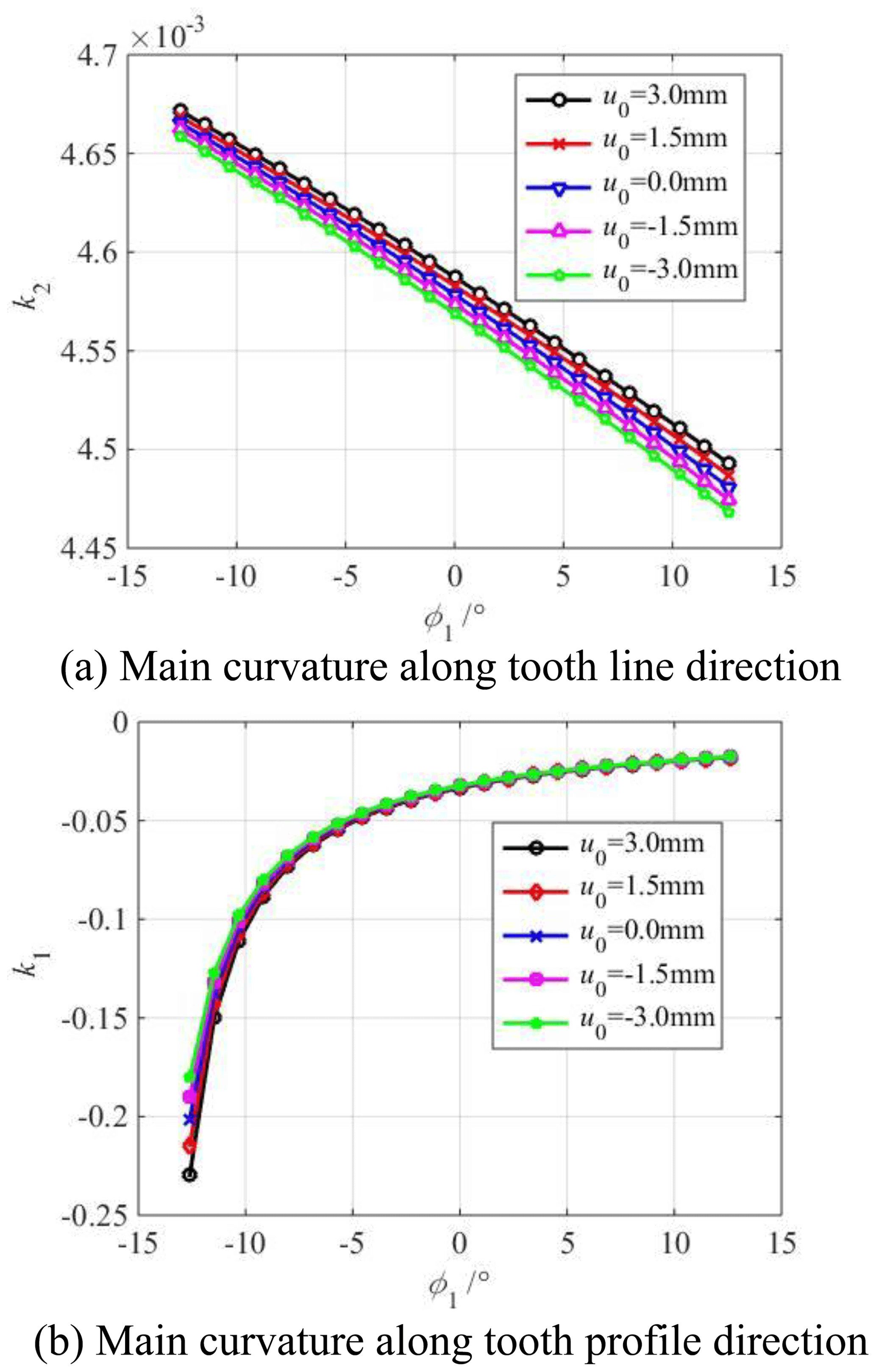
Figure 11Influence of parabolic vertex position u0 on the main curvature of the modified concave tooth surface.
According to Figs. 11a and 12a, the main curvature along the tooth line direction of the concave and convex tooth surfaces increases with the increase in the parabolic vertex position u0 from the tooth root to the tooth top. According to Figs. 11b and 12b, the main curvature along the tooth profile direction of the concave and convex tooth surfaces decreases with the increase in the parabolic vertex position u0 from the tooth root to the tooth top. The larger the parabolic vertex position u0 is, the closer to the tooth top the parabolic vertex is, the more material is removed near the root, the smaller the curvature radius of tooth profile direction is. In addition, the curvature radius near the tooth root is small, so the main curvature of the tooth profile near the tooth root changes greatly.
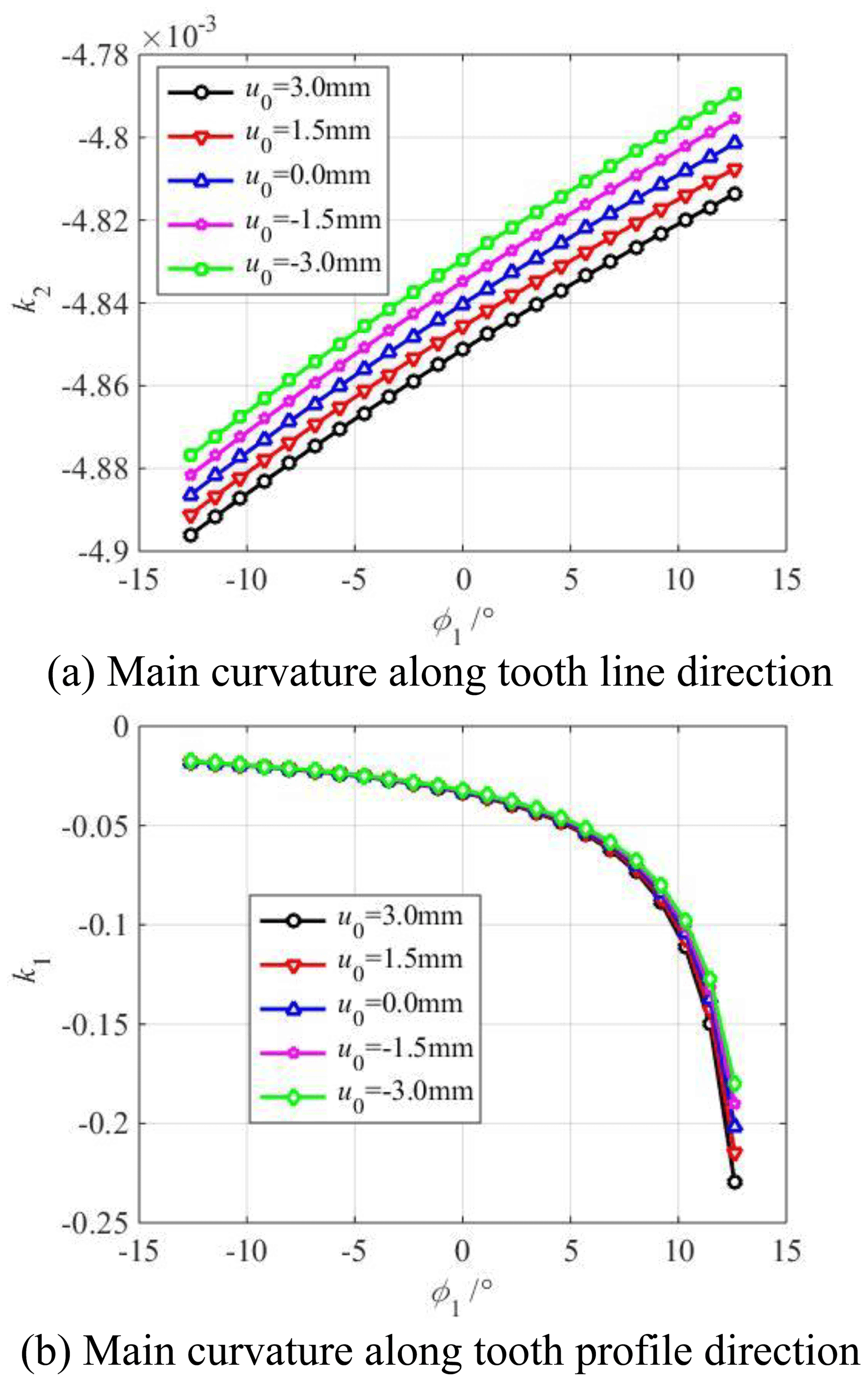
Figure 12Influence of parabolic vertex position u0 on the main curvature of the modified convex tooth surface.
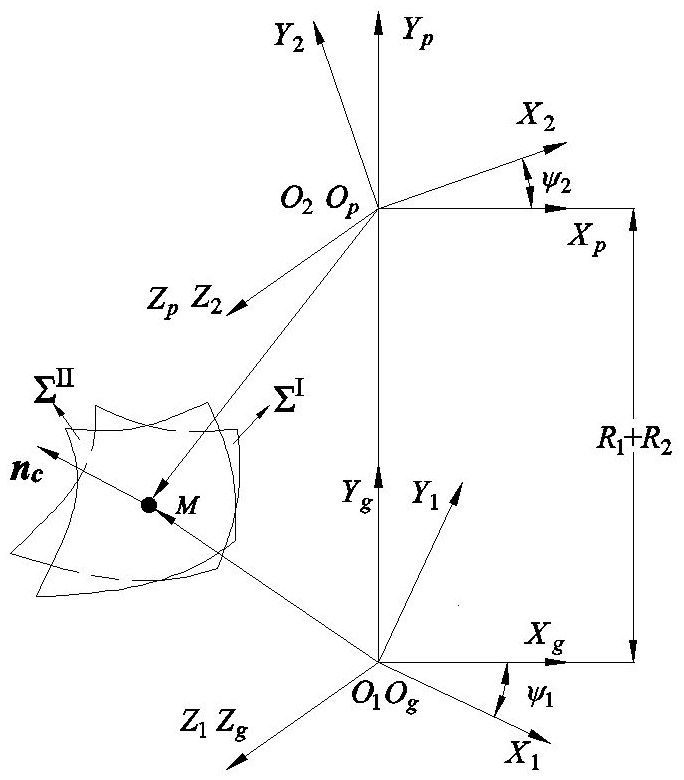
Because the ratio of the elliptic long axis to the gear width is small, the tooth width is not fully used for the gear contact load. To analyse the influence of modification on the elliptical contact area, it is necessary to accurately calculate the meshing points of the VH-CATT cylindrical gear transmission pair first. Therefore, the meshing transmission coordinate system of the VH-CATT cylindrical gear pair is established as shown in Fig. 13. The tooth surfaces of the driving gear are normal (unmodified) and the driven gear are modified. The tooth surface of the driving gear is ΣI and it is the unmodified tooth surface; ΣII is the tooth surface of the driven gear and it is the modified tooth surface; M is the contact point of the tooth surface; nc is the common normal of the contact point, ψ1 is the meshing angle of the driving gear; and ψ2 is the meshing angle of the driven gear. To establish the TCA model of the modified tooth surface, it is necessary to express the tooth surface equation and the normal vector in a fixed coordinate system. In this paper, the OgXgYgZg coordinate system is taken as the calculation fixed coordinate system.
Equation (18) is the tooth contact analysis model, there are 6 unknown variables such as θ1, φ1, ψ1, θ2, φ2, and ψ2 in the model. The driving gear angle ψ1 is the input quantity. According to the tooth top circle of the driven gear, the starting angle of the driving gear angle ψ1 is determined in OpXpYpZp. According to the tooth top circle of the driving gear, the end angle is determined in OgXgYgZg. Then θ1(ψ1), φ1(ψ1), θ2(ψ1), φ2(ψ1), and ψ2(ψ1) can be obtained by solving the nonlinear Eq. (18) and the coordinates of tooth contact points can be obtained further:
5.1 Influence of cutter inclination angle γ on the elliptical contact area
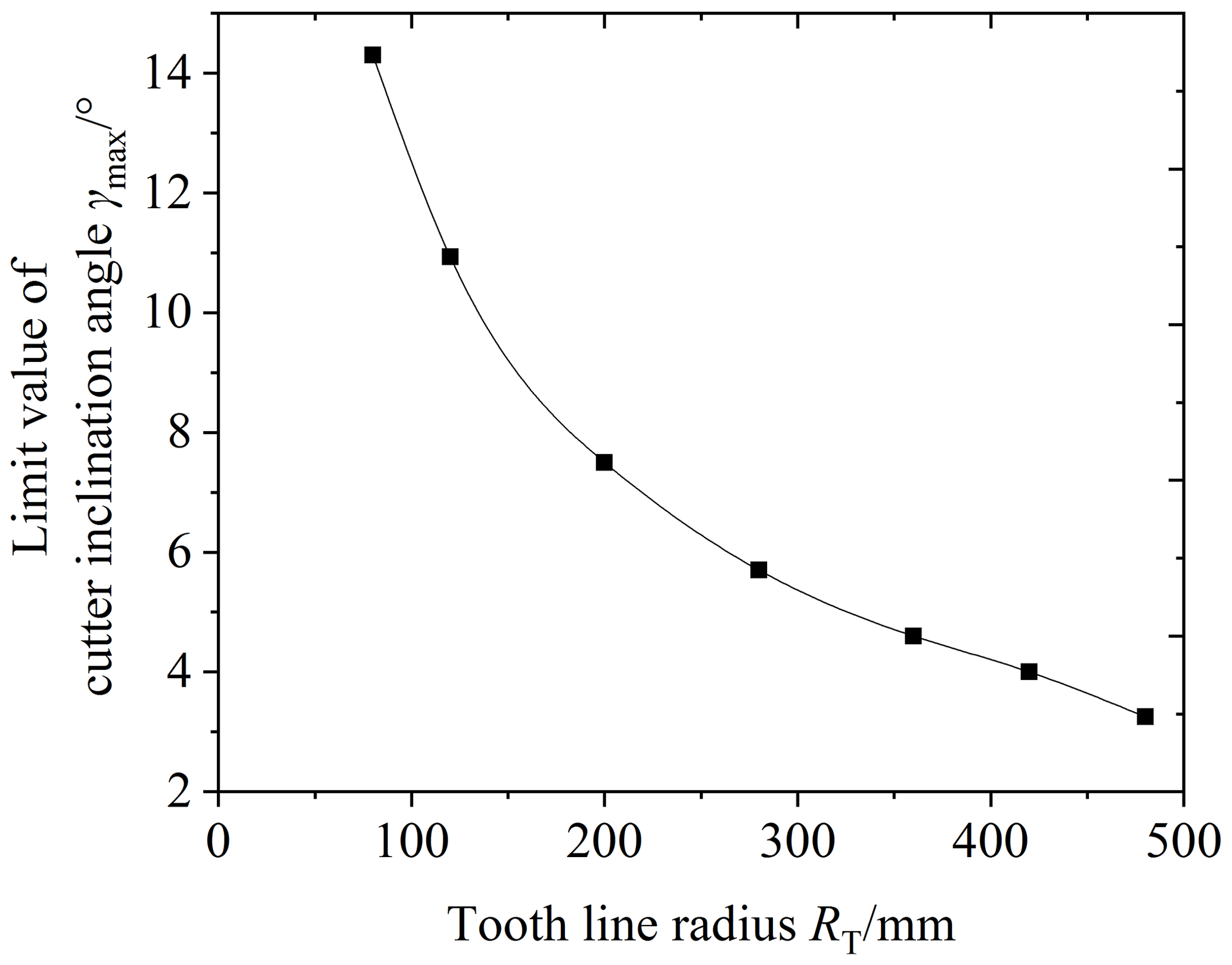
Figure 14 shows the influence of the cutter inclination angle γ on the elliptical contact area. The cutter inclination angle γ is equal to 0 (unmodified), 3, 5, and 7∘, respectively. According to Fig. 14, it is obvious that the elliptical contact area increases with the increase in the cutter inclination angle γ. When the cutter inclination angle γ is between 5 and 7∘, the elliptical contact area increases by a large scale. The reason is the following: when the cutter inclination angle γ increases, the curvature along the tooth line direction of the driven gear's convex tooth surface decreases, and the clearance between the driving and driven surfaces of the gear pair decreases. So the long axis of the contact ellipse increases, shown in Fig. 15. As a result, the elliptical contact area of the gear pair increases. Figure 16 shows the contact model of concave and convex tooth surfaces when the cutter inclination angle γ is equal to 5 and 20∘, respectively. It is obvious that Fig. 16a is the point contact and Fig. 16b is the “bridge” contact. The reason is the following: when the cutter inclination angle γ is too large, the curvature radius of the driven gear convex surface is larger than that of the driving gear concave surface. The “bridge” contact is a kind of contact form that cannot mesh correctly. Therefore, when the cutter inclination method is used to modify tooth surface, the cutter inclination angle γ cannot be greater than a certain limit angle γmax. Tooth surface clearance is an important factor for the elliptical contact area, the larger the tooth surface clearance is, the smaller the elliptical contact area is. The calculation method of tooth surface clearance is given in literature (Fang, 1998) and the calculation method is used to calculate the tooth surface clearance of the modified VH-CATT cylindrical gear system. Additionally, taking the end clearance approaching 0 for the first time (error within 10–4 mm) as the judgement standard, the limit value γmax corresponding to each tooth radius was obtained. Figure 17 shows the relationship between the limit value of cutter inclination angle and tooth line radius. It can be seen from the figure that the larger the tooth radius is, the smaller the limit value of cutter inclination angle is.
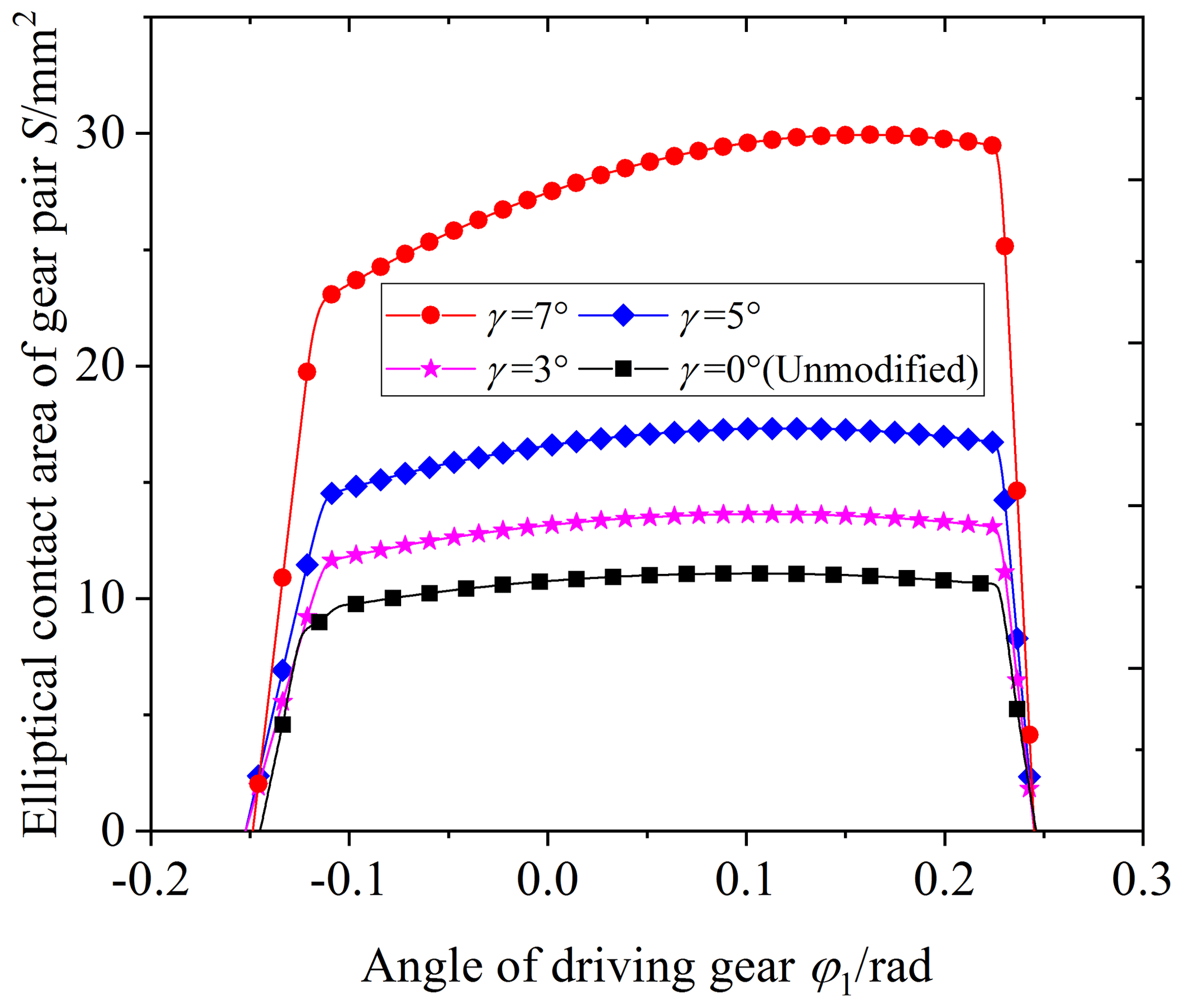
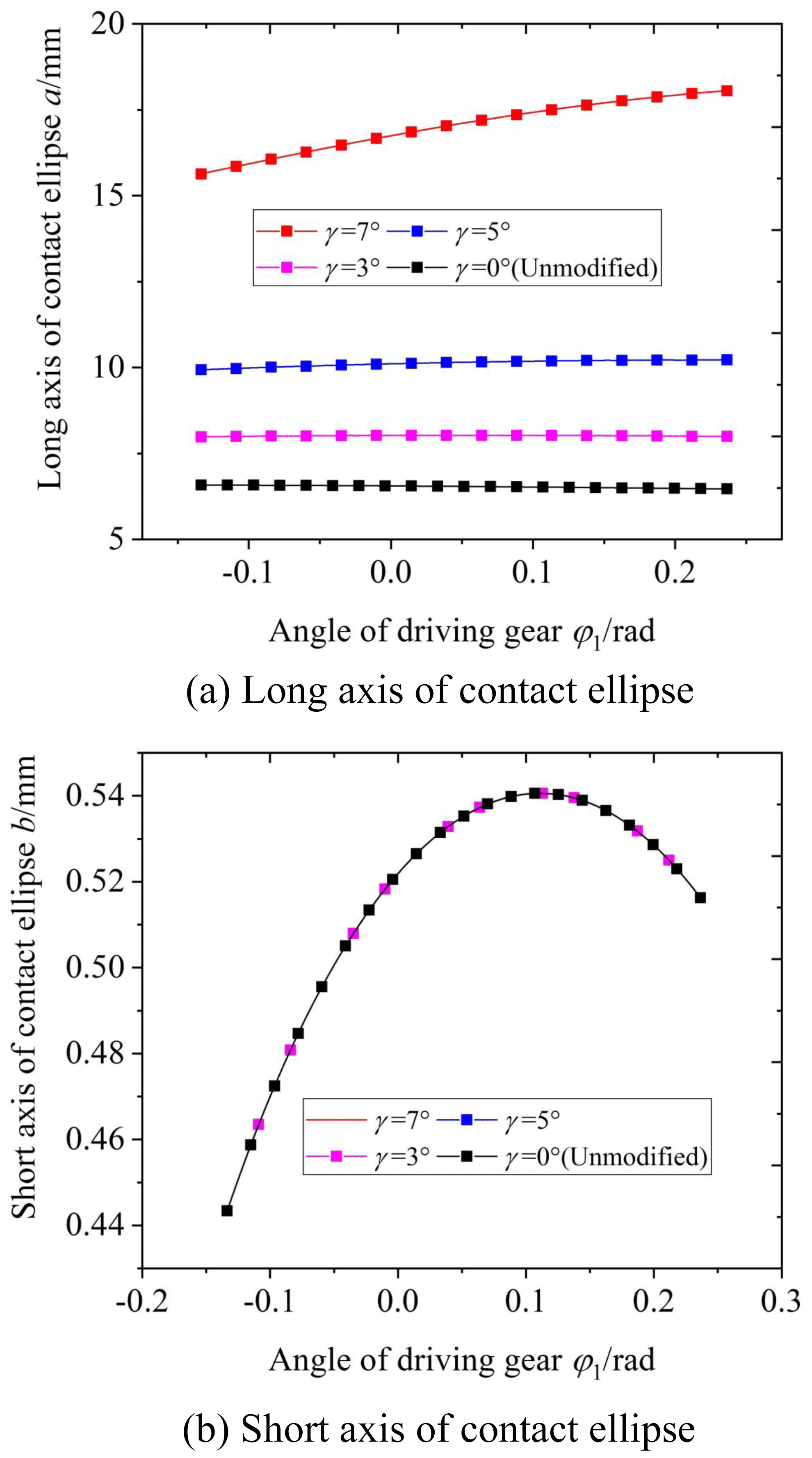
Figure 15Effect of cutter inclination angle γ on the long and short axes of the contact ellipse.
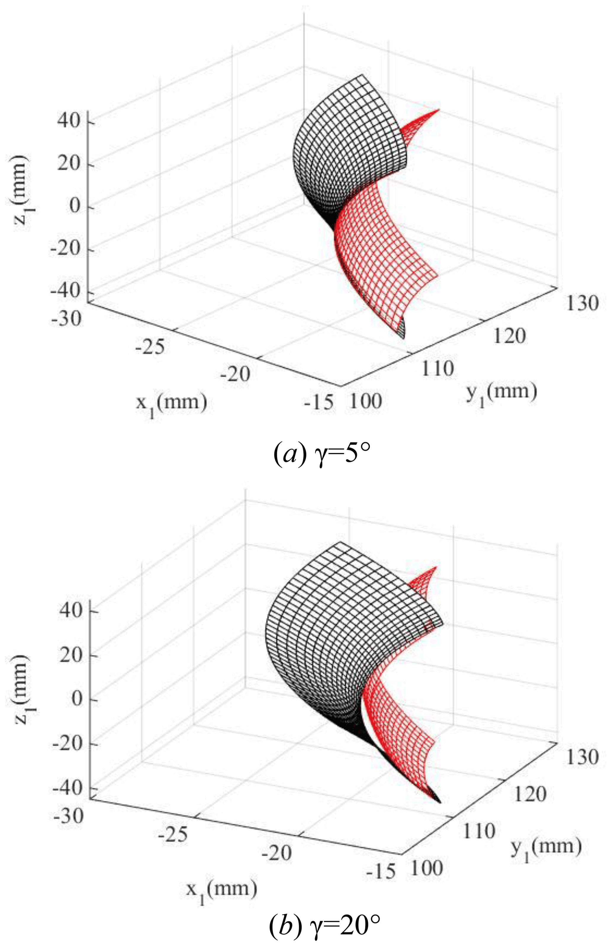
Figure 16Modified gear contact pair (black surface is the driving wheel, and red surface is the driven wheel).
5.2 Influence of parabolic coefficient a on the elliptical contact area
Figure 18 shows the influence of the parabolic coefficient a on the elliptical contact area. The parabolic coefficient a is equal to 0, −0.0001, −0.0005, and −0.001, respectively. According to Fig. 18, it is obvious that the elliptical contact area increases with the increase in the parabolic coefficient a when the contact point is between the tooth root and the pitch circle; it also increases with the decrease in the parabolic coefficient a when the contact point is between the pitch circle and tooth top. According to Figs. 10 and 19, the reason is the following: when the parabolic coefficient increases, the main curvature along the tooth line direction of the driven gear convex tooth surface decreases from the tooth top to the pitch circle, and the curvature radius increases; the main curvature along the tooth line direction of the driven gear convex tooth surface from the pitch circle to the gear top increases, and the curvature radius decreases. As a result, the long axis of the ellipse between the driving tooth root and the pitch circle increases, and the long axis of the ellipse between the pitch circle and the driving tooth top increases. Finally, it leads to the corresponding change of the elliptical contact area. At the same time, it can be seen that although the variation law of the short axis of the ellipse is consistent with that of the elliptical contact area, it is the long axis that mainly affects the contact area.
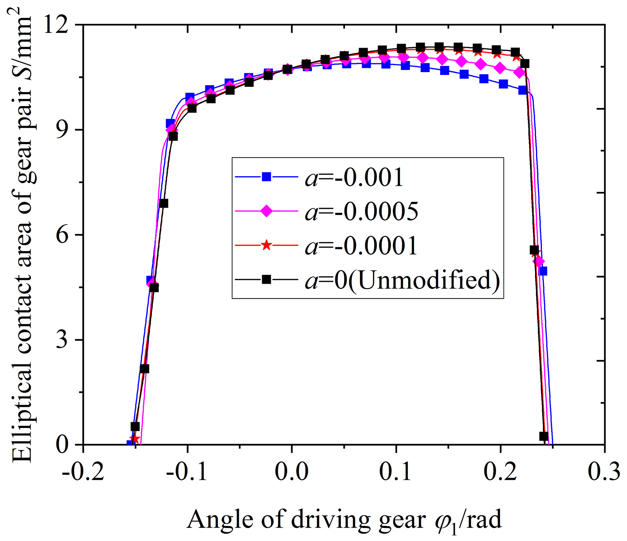
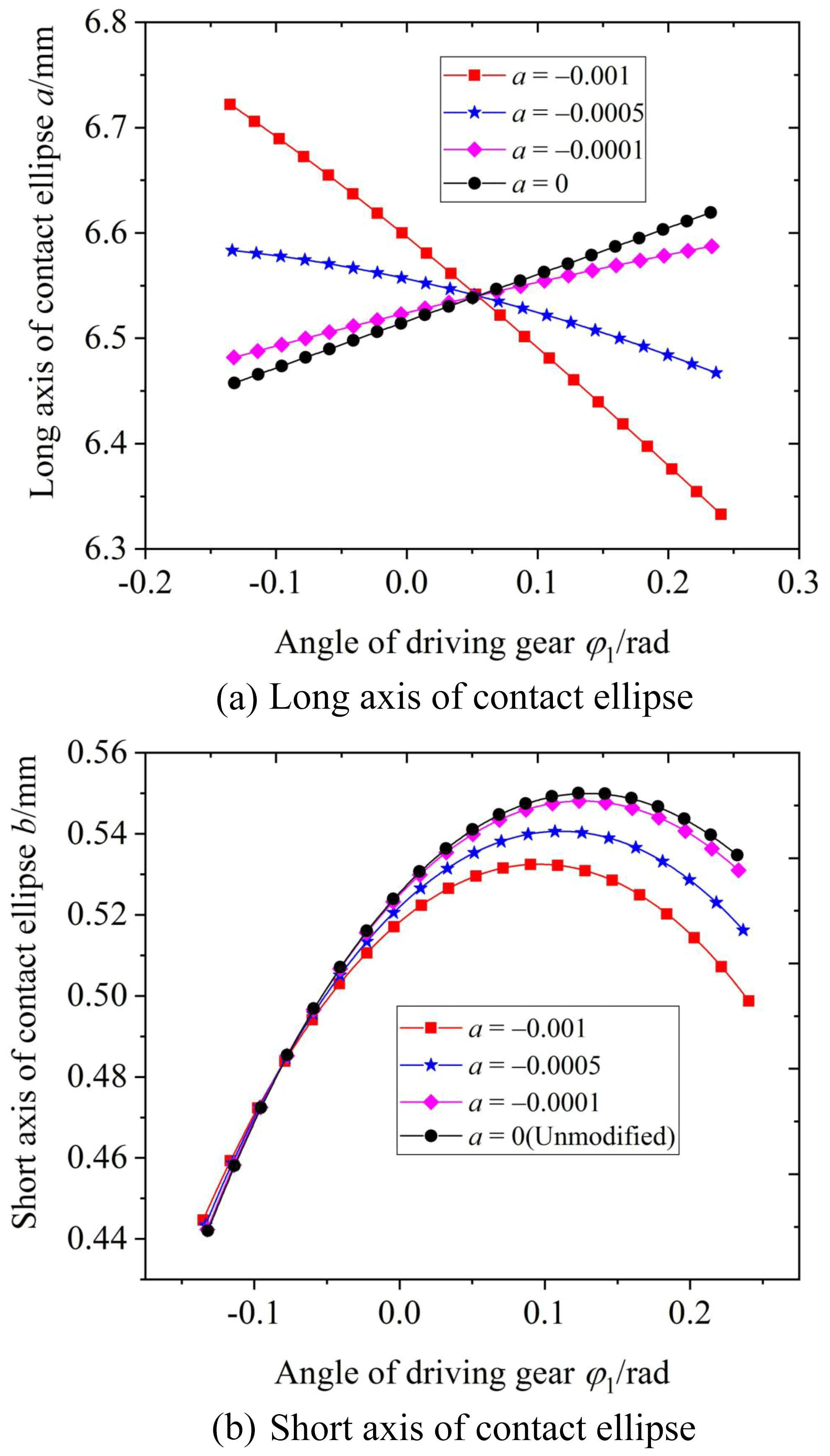
Figure 19Effect of parabolic coefficient a on the long and short axes of the contact ellipse.
5.3 Influence of parabolic vertex position u0 on the elliptical contact area
Figure 20 shows the influence of the parabolic vertex position u0 on the elliptical contact area. The parabolic vertex position u0 is equal to 3, 1.5, 0, −1.5, and −3 mm, respectively. From the graphs, it is obvious that the elliptical contact area decreases with the increase in the parabolic vertex position u0. According to Figs. 12 and 21, the reason is the following: when the parabolic vertex position u0 increases, the main curvature along the tooth line direction of the driven gear convex tooth surface gradually increases, and the curvature radius decreases. As a result, the tooth surface clearance between the driving and driven surfaces increases, the long axis of the contact ellipse decreases, and the elliptical contact area decreases. At the same time, it can be seen that the parabolic vertex position u0 has little influence on the short axis of the contact ellipse, and the main influencing factor of the contact area change is the long axis.

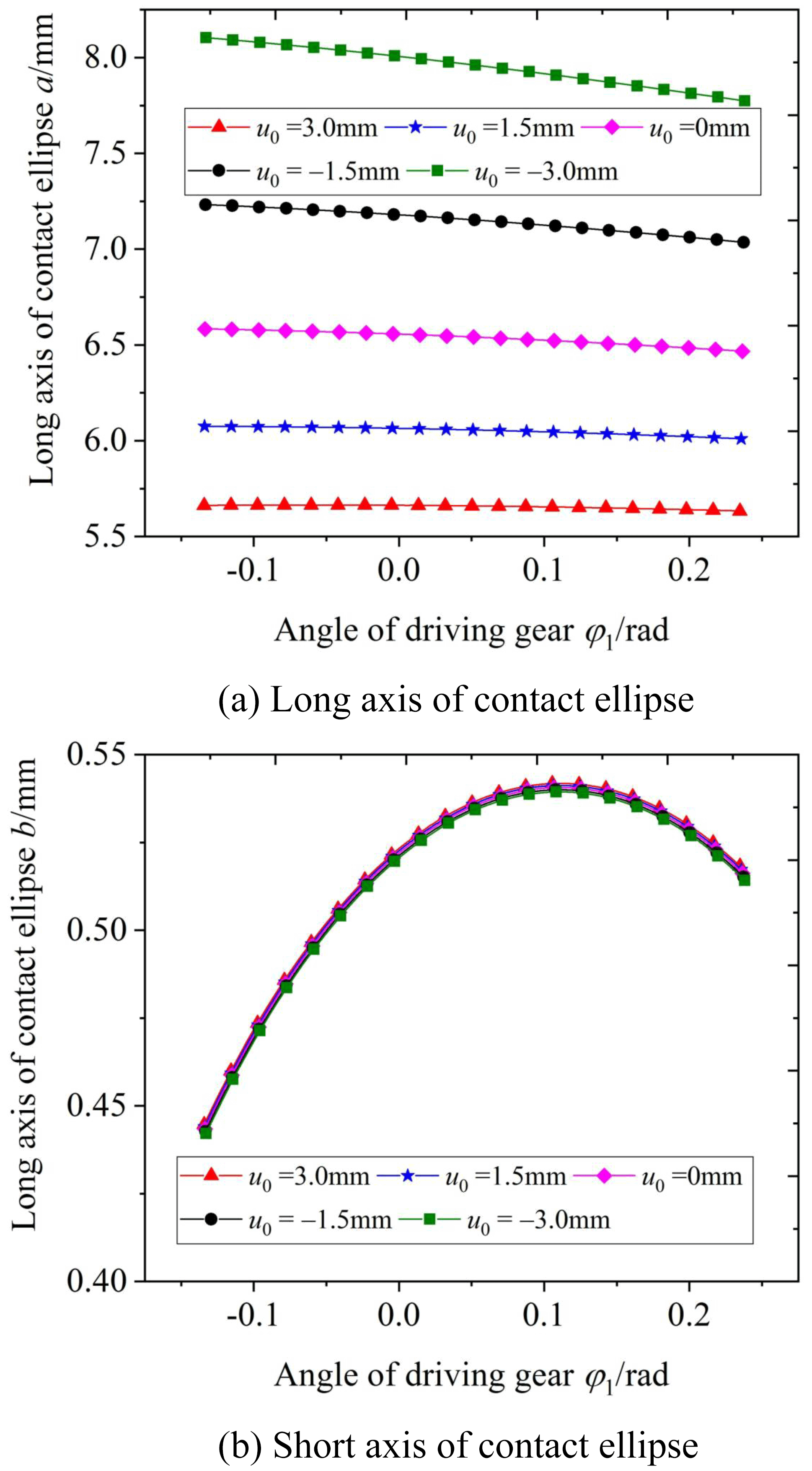
Figure 21Effect of parabolic vertex position u0 on the long and short axes of the contact ellipse.
This paper discusses the surface modification and tooth contact analysis (TCA) of the VH-CATT cylindrical gear. Firstly, the tooth surface modification method was proposed. Next, the modified tooth surface equation was deduced, and the 3D reconstruction is realised. Thereafter, the influence of modification parameters on curvature characteristics was analysed. Finally, the TCA model was established to discuss the influence of modification parameters on the elliptical contact area. The main conclusions can be expressed as follows.
-
The main curvature along the tooth line direction of the concave tooth surface increases with the increase in γ, and the principal curvature of the convex tooth surface is opposite, γ has no effect on the main curvature along the tooth profile. The main curvature along the tooth line direction increases with the increase in a from the tooth root to the pitch circle, but the change rule is opposite from the pitch circle to tooth top; the main curvature along the tooth profile direction increases with the increase in a. The main curvature along the tooth line direction increases with the increase in u0; the main curvature along the tooth profile direction decreases with the increase in u0.
-
The elliptical contact area increases with the increase in γ, and when γ is greater than a certain critical value and the contact form becomes a “bridge” contact, the elliptical contact area increases with the increase in the a between the tooth root and the pitch circle and decreases with the increase in a between the pitch circle to the tooth top. The elliptical contact area decreases with the increase in the value of u0.
-
The modified tooth surface mathematical model of the VH-CATT cylindrical gear can provide a mathematical basis for vibration and noise reduction of the system, and the cutter inclination method can effectively improve the bearing capacity of the system.
All the code and data used in this paper can be obtained upon request to the corresponding author.
DQ and YL conceived the presented idea. DQ and YL established an overall paper research framework and the model. DQ conducted data calculation for the overall paper. All the authors discussed the results and contributed to the final paper.
The contact author has declared that neither of the authors has any competing interests.
Publisher's note: Copernicus Publications remains neutral with regard to jurisdictional claims in published maps and institutional affiliations.
The authors would like to thank anonymous reviewers for their valuable comments and suggestions that enabled us to revise the paper.
This work supported by the National Natural Science Foundation China (grant no. 51765032), the Guizhou Provincial Science and Technology Projects (Qiankehejichu – ZK [2021] yiban 273), the Zunyi Normal University Serving Local Industrial Revolution Project (Zunshihedifangchanyezi [2020] 01), and the Zunyi Normal University 2021 Rural Revitalization Project (Qiaojiaohe KY Zi [2012] 017-5).
This paper was edited by Daniel Condurache and reviewed by three anonymous referees.
Chen, Y. C. and Lo, C. C.: Contact stress and transmission errors under load of a modified curvilinear gear set based on finite element analysis, P. I. Mech. Eng. C-J. Mec., 229, 191–204, https://doi.org/10.1177/0954406214532907, 2015.
Fang, Z.: Model and approach for loaded tooth contact analysis (LTCA) of gear drives, Journal of Mechanical Transmission, 2, 2–4+17+53, 1998.
Fuentes, A., Ruiz-Orzaez, R., and Gonzalez-Perez, I.: Computerized design, simulation of meshing, and finite element analysis of two types of geometry of curvilinear cylindrical gears, Comput. Meth. Appl. Mech. Eng., 272, 321–339, https://doi.org/10.1016/j.cma.2013.12.017, 2014.
Fuentes-Aznar, A., Ruiz-Orzaez, R., and Gonzalez Perez, I.: Comparison of spur, helical and curvilinear gear drives by means of stress and tooth contact analyses, Meccanica, 52, 1721–1738, https://doi.org/10.1007/s11012-016-0515-y, 2017.
Guo, R., Wei, Y., Liu, Y., Li, D., Yang, D., and Zhao, G.: Analytical solution to contact characteristics for a variable hyperbolic circular-arc-tooth-trace cylindrical gear, Mech. Sci., 12, 923–932, https://doi.org/10.5194/ms-12-923-2021, 2021.
Jia, C., Fang, Z., Yao, L., Zhang, J., and Lu, Z.: Tooth modification design for vibration reduction of involute helical gears considering experimental load spectrum, Journal of Central South University (Science and Technology), 52, 3184–3193, 2021.
Jiang, J., Liu, Z., and Liu, H.: Dynamic anti-wear design and analysis for hypoid gears with Ease-off flank modification, Journal of Mechanical Engineering, 57, 155–164, 2021.
Litvin, F. L.: Gear geometry and applied theory, Shanghai Science and Technology Press, Shanghai, China, 2008.
Ma, D., Wei, Y., and Ye, Z.: Mesh contact impact of circular arc tooth traces cylindrical gears, Journal of Vibration and Shock, 37, 123–131, https://doi.org/10.13465/j.cnki.jvs.2018.07.019, 2018.
Ma, D., Ye, Z., and Yang, H.: Tooth surface reconstruction and tooth profile geometric analysis of circular arc tooth trace cylindrical gears, T. Famena, 43, 29–44, https://doi.org/10.21278/TOF.43103, 2019.
Ma, D., Liu, Y., and Ye, Z.: Meshing Contact Impact Properties of Circular Arc Tooth Trace Cylindrical Gear Based on Rotating Knife Dish Milling Process, Math. Probl. Eng., 2021, 8819818, https://doi.org/10.1155/2021/8819818, 2021a.
Ma, D., Liu, Y., Ye, Z., Wei, Y., and Liu J.: Analysis of the tooth surface contact area of a circular arc tooth trace cylindrical gear under load, T. Famena, 45, 79–94, https://doi.org/10.21278/TOF.451018220, 2021b.
Nie, S., Jiang, C., Deng, X., Su, J., Yang, J., and Wang, J.: Flank modification method of hypoid gears with Ease-off topology correction, China Mechanical Engineering, 30, 2709–2715+2740, https://doi.org/10.3969/j.issn.1004-132X.2019.22.010, 2019.
Peng, X., Han, F., Qiao, X., Wang, X., and Kou, F.: Tooth surface active modification and edge contact analysis for face gear drives with helical pinion, Comput. Integr. Manuf., 26, 3040–3048, https://doi.org/10.13196/j.cims.2020.11.014, 2020.
Song, A., Wu, W., Gao, S., and Gao, W.: The ideal geometry parameters of arch cylindrical gear and its process method, Journal of Shanghai Jiaotong University, 44, 1735–1740, 2010.
Tseng, J. T. and Tsay, C. B.: Mathematical model and surface deviation of cylindrical gears with curvilinear shaped teeth cut by a hob cutter, J. Mech. Des.-T. ASME, 127, 982–987, https://doi.org/10.1115/1.1876437, 2005.
Wang, S. J., Hou, L., Dong, L., and Xiao, H. J.: Modeling and strength analysis of cylindrical gears with curvilinear shape teeth for manufacture, Journal of Sichuan University (Engineering Science Edition), 42, 210–215, https://doi.org/10.15961/j.jsuese.2012.02.029, 2012.
Wei, Y., Guo, R., and Liu, Y.: Analytical Calculation of the Tooth Surface Contact Stress of Cylindrical Gear with Variable Hyperbolic Circular Arc Tooth Trace, Symmetry, 12, 1318, https://doi.org/10.3390/SYM12081318, 2020.
Zhang, X. and Xie, Y.: Design, meshing characteristics and stress analysis of cylindrical gears with Curvilinear tooth profile, T. Famena, 40, 27–44, 2016.
Zhao, F., Hou, L., Duan, Y., Chen, Z., Chen, Y., and Sun, Z.: Research on the forming theory analysis and digital model of circular arc gear shaped by rotary cutter, Journal of Sichuan University (Engineering Science Edition), 48, 119–125, https://doi.org/10.15961/j.jsuese.2016.06.017, 2016.
Zhao, F., Hou, L., Chen, Y., and Luo, L.: Mathematical model and generating condition analysis of cylindrical gear with circular-arc-tooth-trace [J]. Journal of Jilin University (Engineering and Technology Edition), 50, 875–885, https://doi.org/10.13229/j.cnki.jdxbgxb20190058, 2020.
- Abstract
- Introduction
- Shaping tool design of tooth surface modification
- Mathematical model of modified tooth surface
- Curvature analysis of modified tooth surface
- Influence of modification parameters on elliptical contact area
- Conclusion
- Code and data availability
- Author contributions
- Competing interests
- Disclaimer
- Acknowledgements
- Financial support
- Review statement
- References