the Creative Commons Attribution 4.0 License.
the Creative Commons Attribution 4.0 License.
 | 14 Sep 2022
A new sensorless control strategy of the PMLSM based on an ultra-local model velocity control system
Zihao Zhang
Shengdi Feng
Jinsong Wang
Xiaoqiang Guo
Hexu Sun
To improve the control performance and dynamic response of the permanent magnet linear synchronous motor (PMLSM), a new sensorless control strategy of the PMLSM with the ultra-local model velocity control system is designed in this paper. Firstly, a model-free speed controller (MFSC) is constructed based on the principle of the ultra-local model. Meanwhile, based on the traditional sliding-mode observer (SMO), the back-electromotive force (BEMF) in the SMO is optimized by the model reference adaptive system (MRAS) to improve the observed speed information of the PMLSM. This control strategy improves the dynamic response ability and stability of the PMLSM system. Compared with the traditional motor control strategy, this design gets rid of the dependence on mechanical sensors, improves the dynamic response ability of the PMLSM, and reduces the velocity tracking error. The superiority of the control system is verified by simulation and experiment. Compared with the traditional dual proportional–integral (PI) control system and SMO, the new control strategy can improve the dynamic response performance of the PMLSM, enhance the stability, and track the speed information of the PMLSM with low error to reduce the chatter.
- Article
(3246 KB) - Full-text XML
- BibTeX
- EndNote


In recent years, due to the continuous progress of science and technology and the continuous development of industrial technology, the permanent magnet linear synchronous motor (PMLSM) has been widely used in various fields of social production, such as the vehicle manufacturing industry, intelligent robot control, manufacturing and production processes (Wen et al., 2020; Dong et al., 2021). The PMLSM has the characteristics of fast dynamic response and high control accuracy, giving it greater advantages in the control of the linear drive system than the rotating motor connected with a ball screw (Xu et al., 2020; Zhao et al., 2021). In the closed-loop control system of the PMLSM, the control performance is often closely related to the accuracy and timeliness of the speed information of the feedback side mover. Because the installation of traditional mechanical sensors will bring defects such as increased cost, increased installation difficulty, and limited application occasions, it is of great significance to apply a sensorless control strategy to the closed-loop motion control of the PMLSM to achieve efficient, reliable, and low-cost direct drive control (Sun et al., 2021).
To solve the problem of multi-disturbance and coupling in the nonlinear complex control systems, some intelligent control strategies of the PMLSM are proposed (Li et al., 2021b; Dan et al., 2021). Modern control strategies widely used in the PMLSM include the sliding-mode control (SMC; Zhang et al., 2022), model-predictive control (Li et al., 2021a), model-free control (Li et al., 2021; Gao et al., 2022; Hashjin et al., 2021) and model reference adaptive control (MRAC; Chen et al., 2019). The model-free control algorithm is a new data-driven control method. It only relies on the input and output variables measured by the controlled system in real time to analyze and design the controller and does not depend on any mathematical model information of the controlled system. Compared with other intelligent control strategies, this control strategy has a simpler structure and better control performance (Wang et al., 2022; Zhang et al., 2021).
To realize the high-precision control of the PMLSM and reduce the dependence on mechanical sensors, the sensorless control strategy of the PMLSM is necessary for its application in various high-precision control technologies and direct drive systems (Zhou et al., 2022). The sensorless control strategy usually uses the observer based on the back-electromotive force (BEMF) of the PMLSM to extract the speed information of the mover (Jayaramu et al., 2021). Common observers include the sliding-mode observer (SMO; Cheng et al., 2022; Sun et al., 2019), extended state observer (Qu et al., 2021), disturbance observer (Cho and Nam, 2020), and adaptive observer (Nair and Narayanan, 2020). Among them, the SMO method is easy to realize and has strong robustness. Meanwhile, the SMC has strong robustness, which is very helpful to the design of the observer. However, the traditional SMO has a high frequency of chattering (Xu et al., 2021; Gong et al., 2020).
This design presents a new sensorless control strategy for the PMLSM based on the ultra-local model velocity control. Compared with the traditional PMLSM strategy, this system first designs a model-free speed controller (MFSC) based on the ultra-local model, which improves the dynamic response performance of the PMLSM and has strong stability. Secondly, the traditional SMO is often designed by a sliding-mode variable structure system. The new SMO designed in this paper optimizes the BEMF of the PMLSM through the model reference adaptive system (MRAS), to reduce the chatter in the PMLSM system and reduce the observation error of the velocity information in the PMLSM. Simulation analysis and experimental verification show that this PMLSM control strategy has better dynamic response performance and lower speed observation error than the dual proportional–integral (PI) controller and SMO.
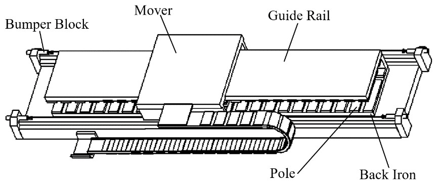
The PMLSM in this design is the surface-mounted PMLSM in Fig. 1.
For the d–q coordinate system, the stator voltage equation of the PMLSM is as follows:
In the Eq. (1), ud and uq represent the stator voltage components of the d–q axes in the PMLSM; Ld and Lq represent the inductive components of the d–q axes in the PMLSM; id and iq represent the current components of the d–q axes in the PMLSM; Rs represents stator resistance in the PMLSM; ωc represents angular velocity of the PMLSM; v represents operating speed in the PMLSM; τ represents polar moment in the PMLSM; and ψf represents permanent magnet flux of the PMLSM.

3.1 Construction of the ultra-local model
The traditional first-order ultra-local model can be obtained as follows (Fliess and Join, 2013):
where, u is the control variable of the system and y is the output variable of the system, α is a nonphysical scale factor of the model, and H is the interference part of the system.
By rewriting Eq. (2), u can be expressed as shown in Eq. (3):
where y∗ is the expected output of the system; is the estimated value of H in the system; and ζ is given by the proportional controller. In Eq. (4),
where represents the tracking error of the system.
When using a PI controller, Eq. (3) can be rewritten as Eq. (5):
where Kp is the proportional gain.
The Laplace transform of Eq. (2) is obtained:
Differentiate both sides of Eq. (6) with respect to s, and obtain the following:
After eliminating the influence of noise in the time domain and multiplying Eq. (7) by s2, the inverse Laplace transform is carried out, and the estimated value of the unknown part of the control system in the time domain is
where Z is a value within the sampling period, depending on the sampling period and noise, where .
3.2 The MFSC of PMLSM
The ultra-local model in the PMLSM is constructed based on Eq. (2) as follows:
where Hq represents the unknown part of the internal and external interference factors of the PMLSM, αq represents the stator current coefficient of the q axis in the PMLSM. The following equation can be obtained by rewriting Eq. (8):
where is the estimated value of in the PMLSM system, and Ts represents the sampling time in the PMLSM system.
The value is estimated and calculated online by Eq. (10). Meanwhile, the d-axis reference value in the PMLSM system is set to 0 and the complex trapezoid equation is used for calculation:
where c represents the sampling step size of the PMLSM system, represents the current sampling value in the PMLSM and ν[n] represents the speed sampling value in the PMLSM.
The current estimation of the q axis for the MFSC in the PMLSM system can be calculated by Eq. (5):
where represents the current estimation of the q axis; and v are the reference value and actual value of the operating speed of the PMLSM system, respectively. Figure 2 shows the block diagram of the MFSC system based on the PMLSM ultra-local model.
To simplify the structure of the PMLSM system and reduce the chattering phenomenon in the traditional SMO, this design optimizes the BEMF of the PMLSM through the MRAS based on the traditional SMO.
4.1 Establishment of traditional SMO
Since the motor used in this paper is a surface-mounted PMLSM, there is . Equation (1) can be rewritten to obtain the following equation:
where q denotes the differential operator, eα and eβ are the extended BEMFs in the PMLSM. Meanwhile, the following equation is satisfied:
To observe the BEMF of the PMLSM with SMO, the voltage equation of Eq. (13) is rewritten into the state equation of current:
To obtain the estimated value of the extended BEMF, Eq. (15) is rewritten:
where and are observations of the stator current. The error of the current in the PMLSM can be obtained by subtraction between Eqs. (15) and (16):
where and represent the observation errors of the current. The SMC law is designed as follows:
where .
When the state variables of the observer reach the sliding surfaces and , the observer state will always remain on the sliding surface. According to the equivalent control principle of the SMC, the control quantity at this time can be regarded as the equivalent control quantity. The observed values of the BEMF in the two-phase stationary coordinate system are as follows:

4.2 Optimization of BEMF based on MRAS
By taking the derivative of Eq. (14), the following equation can be obtained:
Since the change speed of the motor is very slow, it can be determined that . In combination with Eq. (14), the above equation can be simplified as follows:
Taking Eq. (21) as the reference model of the adaptive law of the BEMF, the adjustable model is established as follows:
where is the estimate value of ωc, and are expressed by the following equation:
where l>0. The following equation can be obtained by making a difference between Eqs. (22) and (21):
where, ,.
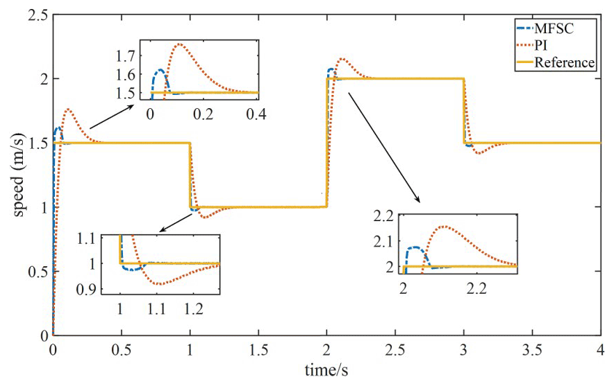
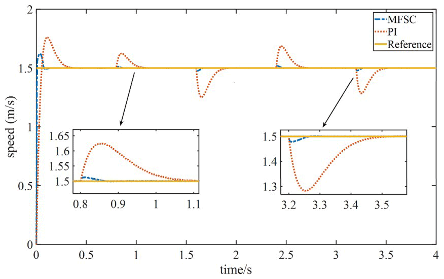
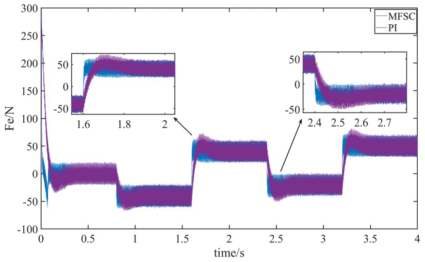
Figure 8The thrust waveforms of the two controllers under variable load motion are compared.
According to Popov's hyperstability theory, to prove whether the system is stable, the following two conditions must be met: (1) The transfer function matrix of the system is strictly a positive definite; (2) Popov's integral inequality , holds, where , , is any finite real number.
For condition (1), the transfer function matrix of the system is
Equation (25) shows that the transfer function is strictly a positive definite and condition (1) holds.
For condition (2), it is assumed that the mechanism of the adaptive law of the MRAS is as follows:
When substituting V and W into η(0,t1) of condition (2), the following is obtained:
The combination of Eqs. (26) and (27) obtains the following:
For η1(0,t1) in Eq. (28),
where ke is an arbitrary value and satisfies . According to inequality,
where it can be proved that .
For η2(0,t1) in Eq. (28), let . According to Eq. (30) and the arbitrary value of F2(ve,t), it can also be proved that . From the above proof process, it can be concluded that condition (2) of Popov's hyperstability theory holds, proving that the system is stable. According to Eq. (28), and , the adaptive law of the system can be obtained as follows:
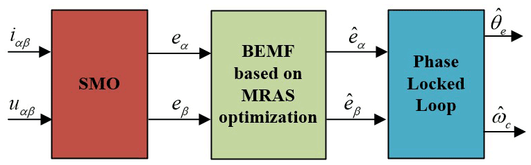
By selecting an appropriate value of l, the adjustable model shown in Eq. (22), which is established by taking the observed value of the BEMF output by the traditional SMO as the reference model, can obtain a relatively smooth BEMF after being adjusted by the adaptive law of Eq. (31), thereby further reducing the chattering phenomenon of the SMO. The SMO system block diagram based on the MRAS optimization is shown in Fig. 3.


4.3 Design of phase-locked loop
In this paper, the speed information in the BEMF is extracted by a phase-locked loop (PLL). Set
The error signal in the PLL is
The value of is minimal when the system approaches the steady state. Assuming , after normalization, the error signal of the observer is
The closed-loop transfer equation of the PLL from to θe is as follows:
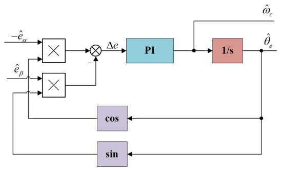
where , . The PI controller's bandwidth is represented by ωn and kpki represent normal numbers. Figure 4 shows the system block diagram of the PLL.

5.1 System simulation
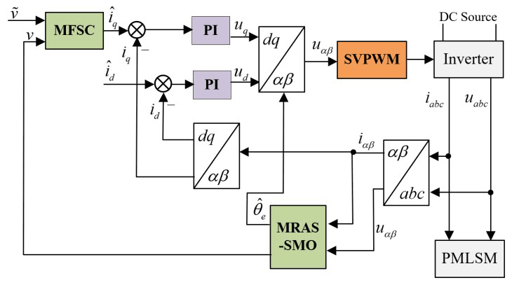
The design is verified by the MATLAB/Simulink simulation platform. The model of this control strategy in the simulation platform is constructed according to the motor parameters in Table 1. By comparing the speed waveform and load thrust waveform of the MFSC controller based on the ultra-local model and the traditional PI controller designed in this design under variable speed motion and variable load motion,the designed MFSC controller is shown to have better dynamic response ability. On this basis, the SMO based on the MRAS optimization is added and compared with the traditional SMO to observe the speed tracking performance of the two observers under variable speed motion. Figure 5 shows the establishment of this design. The system sampling time is 1 µs.
A. Change speed
To test the dynamic response ability of the PMLSM system in the case of increase and decrease in speed, the system performs variable speed movement in the order of 1.5 → 1 → 2 → 1.5 m s−1. Figure 6 shows the speed waveform changes of the MFSC controller and the PI controller in the case of the variable speed motion. In Fig. 6, the overshoot and settling time of the MFSC controller is less than that of the PI controller when the speed suddenly increases to 2 m s−1. For example, the speed overshoot of the MFSC controller is about half of that of the PI controller, and the settling time is about one-fourth of that of the PI controller. It can be concluded that the MFSC controller has better dynamic response ability and control performance than the PI controller.
B. The speed remains unchanged and the load changes
To test the anti-disturbance ability of the PMLSM system under sudden load increase and sudden load drop, 40, 80, 60, 70 N, loads are applied in sequence under the given system speed of 1.5 m s−1. Figure 7 shows the speed waveforms of the MFSC controller and the PI controller under sudden load increase and sudden load decrease. In Fig. 7,the dynamic drop amount and settling time of the MFSC controller are far less than that of the PI controller. Therefore, the anti-disturbance ability of the MFSC controller is stronger than that of the PI controller.
The thrust waveforms of the MFSC controller and PI controller under variable load motion is shown in Fig. 8. In this figure, the MFSC controller's thrust waveform is smoother than that of the PI controller and can reach the load value quickly with almost no overshoot. It can be seen that the MFSC controller is more stable than the PI controller.
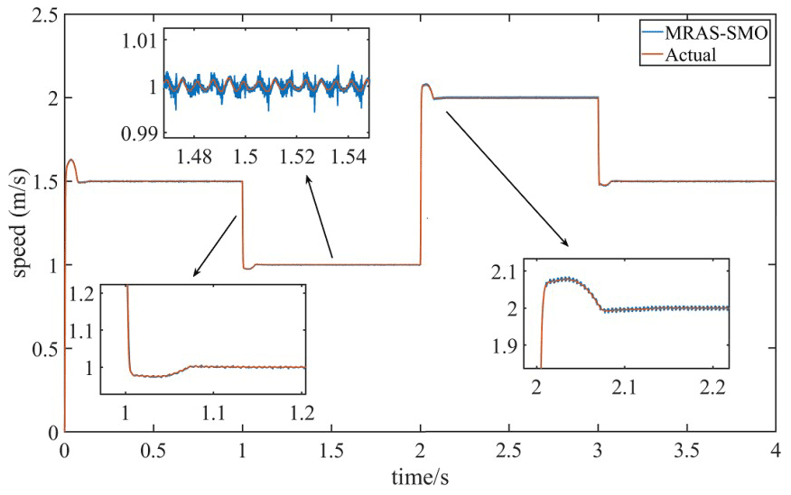
C. Observer comparison
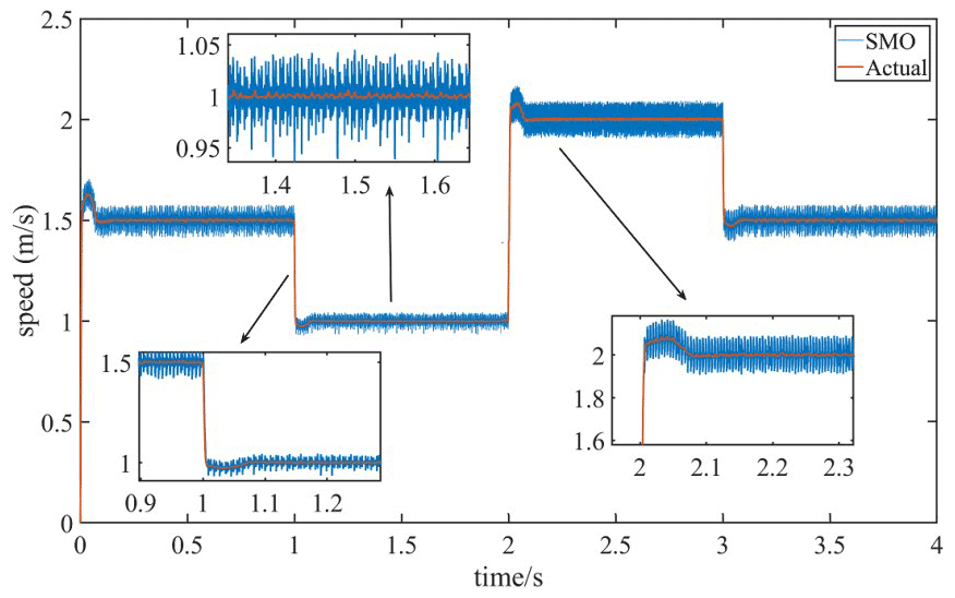
To compare the speed tracking performance of the designed SMO based on the MRAS optimization and the traditional SMO, the speed observed by the two observers is compared with the actual speed when the system is moving at variable speed. Figures 9 and 10 are speed tracking performance comparison charts of the MRAS–SMO and SMO, respectively. In Figs. 9 and 10, the estimated speed waveform of the MRAS–SMO is closer to the actual speed waveform than that of the SMO, with less jitter and a more stable waveform. When the system speed is stable at 1 m s−1, the buffeting amplitudes of the estimated velocity waveforms of the MRAS–SMO and SMO are 0.003 and 0.007 m s−1, respectively. Therefore, the velocity tracking performance of the MRAS–SMO is better than that of the SMO.
5.2 Experimental
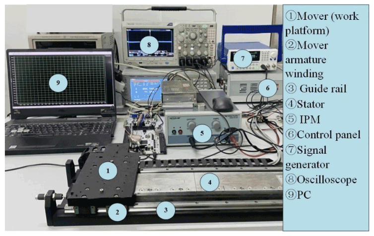
This design is verified by using a TMS320F28335 digital processing chip to achieve control, as shown in Fig. 11. During the operation of the PMLSM, the built-in mechanical sensor transmits the current signal to the control board for closed-loop control operation. Compare the waveform used by the observer and the performance of the motor in the process of variable speed tracking. The PMLSM's parameters in the experimental process are the same as the linear motor parameters set in the simulation.
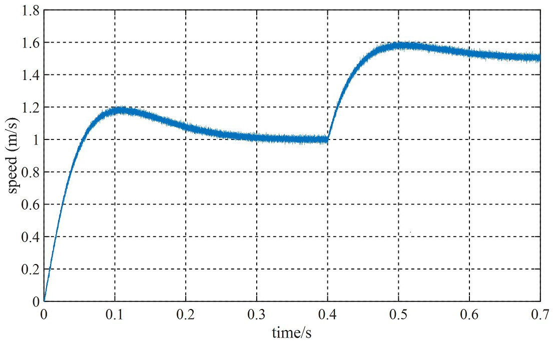
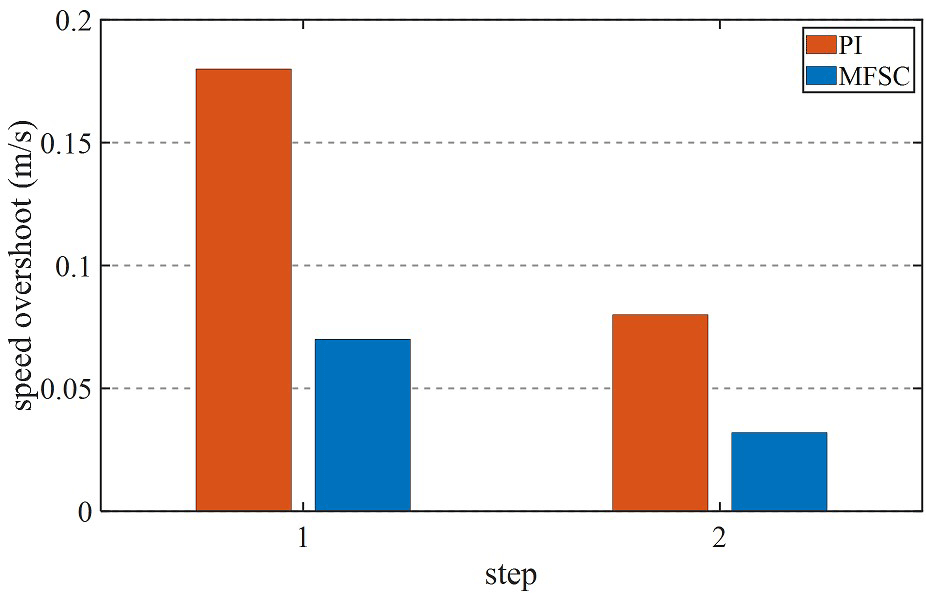
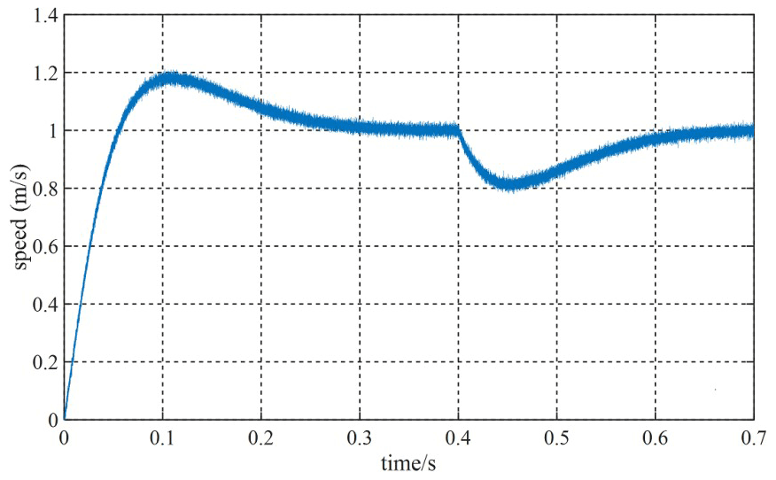
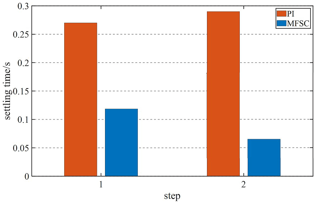
Given the fact that the system speed is 1 m s−1, and the speed will be increased to 1.5 m s−1 at 0.4 s, Figs. 12 and 13 are velocity waveforms of the PI controller and the MFSC controller under variable velocity motion, respectively. Figures 14 and 15, respectively show the speed overshoot and settling time of MFSC controller and PI controller under variable speed movement through bar charts. It can be seen in Figs. 14 and 15 that the speed overshoot and settling time of the MFSC controller in the two stages of the variable velocity motion are less than those of the PI controller. Relative to the PI controller, the MFSC controller has better dynamic response ability.
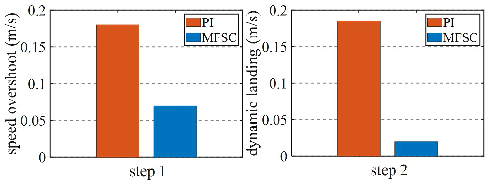
Given the system speed of 1 m s−1, apply 60 N load at 0.4 s. Figures 16 and 17 show the speed waveforms of the two controllers under the load motion. Figures 18 and 19, respectively show the speed overshoot, dynamic landing and settling time of the two controllers in the load movement through bar charts. It can be seen from Figs. 18 and 19 that the speed overshoot, dynamic landing and settling time of the MFSC controller in the two stages of load motion are smaller than those of the PI controller, and the MFSC controller has better anti-disturbance ability and stability than the PI controller.
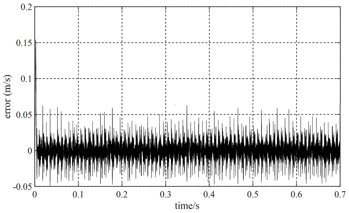
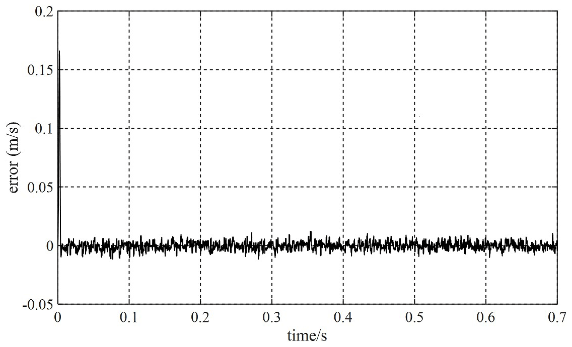
Based on the MFSC controller, the MRAS–SMO and the SMO are added, respectively, and the velocity tracking ability of the two observers is compared when the given velocity of the PMLSM is 1 m s−1. Figures 20 and 21 show the velocity tracking errors of the SMO and MRAS–SMO, respectively. Compared with Figs. 20 and 21 and relative to the SMO, the MRAS–SMO has less of a velocity tracking error. This indicates that the MRAS–SMO has a smaller tracking error than the SMO.
To solve the problems of speed fluctuation, slow response, sensor dependence and mechanical jitter in the PMLSM motion, a new sensorless control strategy based on the ultra-local model speed control is proposed in this design. The MFSC is designed based on the ultra-local model. Meanwhile, the MRAS is used to optimize the BEMF observed in the traditional SMO, to reduce the chatter and enhance the speed tracking performance. Simulation analysis and experimental results show that, relative to the PI controller and the SMO, the control system can get rid of the dependence on mechanical sensors, improve the stability and dynamic response ability of the system, and reduce the tracking error of the system speed. The limitation of this design is when the linear motor is running at high speed, the speed waveform has a chattering phenomenon, which should be further improved in future research. In conclusion, this control strategy has a reference value for the PMLSM system control structure.
As the research results in this article will be used as the basis for further exploration in subsequent work, the relevant codes will not be disclosed.
The simulation conditions and relevant parameters are given in Table 1, and the effective data obtained are represented in the form of waveform diagrams (Figs. 6–21).
ZL and HS were responsible for writing, reviewing, and editing the paper; supervision; project management; and funding acquisition. ZZ and JW were responsible for developing the methods, running simulations, carrying out experimental verification, and writing the original draft of the paper. SF and XG were responsible for writing the manuscript and confirming the information.
The contact author has declared that none of the authors has any competing interests.
Publisher's note: Copernicus Publications remains neutral with regard to jurisdictional claims in published maps and institutional affiliations.
The authors are grateful to the National Nature Foundation of China (grant nos. 51877070, U20A20198, and 51577048) and the Natural Science Foundation of Hebei Province (grant no. E2021208008) for their support. The platform of Hebei University of Science and Technology is also acknowledged. Moreover, the authors wish to thank the reviewers for their comments, which helped us complete the revision of the article.
This work has been supported by the National Natural Science Foundation of China (grant nos. 51877070, U20A20198, and 51577048); the Natural Science Foundation of Hebei Province of China (grant no. E2021208008); the Talent Engineering Training Support Project of Hebei Province (grant no. A201905008); and the National Engineering Laboratory of Energy-saving Motor and Control Technique, Anhui University (grant no. KFKT201901).
This paper was edited by Zi Bin and reviewed by two anonymous referees.
Chen, S.-Y., Chiang, H.-H., Liu, T.-S., and Chang, C.-H.: Precision Motion Control of Permanent Magnet Linear Synchronous Motors Using Adaptive Fuzzy Fractional-Order Sliding-Mode Control, IEEE-ASME T. Mech., 24, 741–752, https://doi.org/10.1109/TMECH.2019.2892401, 2019.
Cheng, H., Sun, S., Zhou, X., Shao, D., Mi, S., and Hu, Y.: Sensorless DPCC of PMLSM Using SOGI-PLL-Based High-Order SMO With Cogging Force Feedforward Compensation, IEEE Transactions on Transportation Electrification, 8, 1094–1104, https://doi.org/10.1109/TTE.2021.3109018, 2022.
Cho, K. and Nam, K.: System Identification Method Based on a Disturbance Observer Using Symmetric Reference Trajectories in PMLSM-Based Motion Systems, IEEE Access, 8, 216197–216209, https://doi.org/10.1109/ACCESS.2020.3042343, 2020.
Dan, H., Zeng, P., Xiong, W., Wen, M., Su, M., and Rivera, M.: Model predictive control-based direct torque control for matrix converter-fed induction motor with reduced torque ripple, CES Transactions on Electrical Machines and Systems, 5, 90–99, https://doi.org/10.30941/CESTEMS.2021.00012, 2021.
Dong, F., Zhao, J., Zhao, J., Song, J., Chen, J., and Zheng, Z.: Robust Optimization of PMLSM Based on a New Filled Function Algorithm With a Sigma Level Stability Convergence Criterion, IEEE T. Ind. Inform., 17, 4743–4754, https://doi.org/10.1109/TII.2020.3020070, 2021.
Fliess, M. and Join, C.: Model-free control, Int. J. Control, 86, 2228–2252, https://doi.org/10.1080/00207179.2013.810345, 2013.
Gao, S., Wei, Y., Zhang, D., Qi, H., Wei, Y., and Yang, Z.: Model-Free Hybrid Parallel Predictive Speed Control Based OnUltralocal Model of PMSM for Electric Vehicles, IEEE T. Ind. Electron., 69, 9739–9748, https://doi.org/10.1109/TIE.2022.3159951, 2022.
Gong, C., Hu, Y., Gao, J., Wang, Y., and Yan, L.: An Improved Delay-Suppressed Sliding-Mode Observer for Sensorless Vector-Controlled PMSM, IEEE T. Ind. Electron., 67, 5913–5923, https://doi.org/10.1109/TIE.2019.2952824, 2020.
Hashjin, S. A., Corne, A., Pang, S., Ait-Abderrahim, K., Miliani, E.-H., and Nahid-Mobarakeh, B.: Current Sensorless Control for WRSM Using Model-Free Adaptive Control, IEEE Transactions on Transportation Electrification, 7, 683–693, https://doi.org/10.1109/TTE.2020.3030111, 2021.
Jayaramu, M. L., Suresh, H. N., Bhaskar, M. S., Almakhles, D., Padmanaban, S., and Subramaniam, U.: Real-Time Implementation of Extended Kalman Filter Observer With Improved Speed Estimation for Sensorless Control, IEEE Access, 9, 50452–50465, https://doi.org/10.1109/ACCESS.2021.3069676, 2021.
Li, X., Wang, Y., Guo, X., Cui, X., Zhang, S., and Li, Y.: An Improved Model-Free Current Predictive Control Method for SPMSM Drives, IEEE Access, 9, 134672–134681, https://doi.org/10.1109/ACCESS.2021.3115782, 2021.
Li, Z., An, J., Zhang, Q., Liu, H., and Sun, H.: Design of PMSLM Position Controller Based on Model Predictive Control Algorithm, IEEE Access, 9, 78835–78846, https://doi.org/10.1109/ACCESS.2021.3083521, 2021a.
Li, Z., Wang, J., An, J., Zhang, Q., and Zhu, Y.: Variable Gain Cross-Coupling Control System of Dual-Axis PM Synchronous Linear Motor Based on Model Predictive Speed and Current Integrated Controller, in: Proceedings of the 13th International Symposium on Linear Drives for Industry Applications (LDIA), Wuhan, China, 1–3 July 2021, 1–6, https://doi.org/10.1109/LDIA49489.2021.9505734, 2021b.
Nair, R. and Narayanan, G.: Stator Flux Based Model Reference Adaptive Observers for Sensorless Vector Control and Direct Voltage Control of Doubly-Fed Induction Generator, IEEE T. Ind. Appl., 56, 3776–3789, https://doi.org/10.1109/TIA.2020.2988426, 2020.
Qu, Y., Lu, J., Li, H., and Niu, X.: Sensorless Control of Permanent-Magnet Linear Synchronous Motor Based on Modified Linear Extended State Observer, in: 2021 13th International Symposium on Linear Drives for Industry Applications (LDIA), Wuhan, China, 1–3 July 2021, 1–6, https://doi.org/10.1109/LDIA49489.2021.9505766, 2021.
Sun, J., Cao, G.-Z., Huang, S.-D., Peng, Y., He, J., and Qian, Q.-Q.: Sliding-Mode-Observer-Based Position Estimation for Sensorless Control of the Planar Switched Reluctance Motor, IEEE Access, 7, 61034–61045, https://doi.org/10.1109/ACCESS.2019.2913702, 2019.
Sun, X., Wu, M., Yin, C., Wang, S., and Tian, X.: Multiple-Iteration Search Sensorless Control for Linear Motor in Vehicle Regenerative Suspension, IEEE Transactions on Transportation Electrification, 7, 1628–1637, https://doi.org/10.1109/TTE.2021.3052989, 2021.
Wang, P., Yuan, X., and Zhang, C.: An Improved Model Free Predictive Current Control for PMSM With Current Prediction Error Variations, IEEE Access, 10, 54537–54548, https://doi.org/10.1109/ACCESS.2022.3175501, 2022.
Wen, T., Wang, Z., Xiang, B., Han, B., and Li, H.: Sensorless Control of Segmented PMLSM for Long-Distance Auto-Transportation System Based on Parameter Calibration, IEEE Access, 8, 102467–102476, https://doi.org/10.1109/ACCESS.2020.2998731, 2020.
Xu, W., Junejo, A. K., Tang, Y., Shahab, M., Rahman Habib, H. U., and Liu, Y., and Huang, S.: Composite Speed Control of PMSM Drive System Based on Finite Time Sliding Mode Observer, IEEE Access, 9, 151803–151813, https://doi.org/10.1109/ACCESS.2021.3125316, 2021.
Xu, X., Sun, Z., Du, B., and Ai, L.: Pole Optimization and Thrust Ripple Suppression of New Halbach Consequent-Pole PMLSM for Ropeless Elevator Propulsion, IEEE Access, 8, 62042–62052, https://doi.org/10.1109/ACCESS.2020.2984281, 2020.
Zhang, K., Wang, L., and Fang, X.: High-Order Fast Nonsingular Terminal Sliding Mode Control of Permanent Magnet Linear Motor Based on Double Disturbance Observer, IEEE T. Ind. Appl., 58, 3696–3705, https://doi.org/10.1109/TIA.2022.3162571, 2022.
Zhang, Y., Jin, J., and Huang, L.: Model-Free Predictive Current Control of PMSM Drives Based on Extended State Observer Using Ultralocal Model, IEEE T. Ind. Electron., 68, 993–1003, https://doi.org/10.1109/TIE.2020.2970660, 2021.
Zhao, J., Mou, Q., Zhu, C., Chen, Z., and Li, J.: Study on a Double-Sided Permanent-Magnet Linear Synchronous Motor With Reversed Slots, IEEE-ASME T. Mech., 26, 3–12, https://doi.org/10.1109/TMECH.2020.2987106, 2021.
Zhou, S., Li, Y., Shi, L., Guo, K., Zhang, M., and Liu, J.: Sensorless Control of Segmented Long Stator PMLSM Based on Inductance Disturbance Compensation, in: 2022 IEEE 5th International Electrical and Energy Conference (CIEEC), Nangjing, China, 27–29 May 2022, 1865–1869, https://doi.org/10.1109/CIEEC54735.2022.9846495, 2022.
- Abstract
- Introduction
- The structure and mathematical model of the PMLSM
- Establishment of the MFSC for the PMLSM
- Design of improved SMO
- Simulation and experimental of the PMLSM system
- Conclusion
- Code availability
- Data availability
- Author contributions
- Competing interests
- Disclaimer
- Acknowledgements
- Financial support
- Review statement
- References