the Creative Commons Attribution 4.0 License.
the Creative Commons Attribution 4.0 License.
 | 08 Aug 2022
An innovative device for enlarging the allowable misalignment for screwing tasks
Hao-Tien Ku
Yu-Hsun Chen
To ensure the repeatability in a screwing task, the robot manipulators have to be calibrated regularly. If the allowable position error of the manipulator is increased, then the frequency of stopping a production line and calibrating the manipulators can be lower; therefore, the cost can be also decreased. This paper presents an innovative device for enlarging the allowable misalignment (DEAM) with five mechanisms, namely detecting, trigger, positioning, pin-and-stopper, and screwing mechanisms. By scanning around the target threaded hole, the screw can be precisely positioned at the location where the hole is detected by the probe. The motion and force analysis are carried out and verified through computer-aided simulation, and the sensitivity of the linkage tolerance is analyzed to ensure that the output position error of the mechanism does not affect the function of the device. Finally, the performance of the innovative device is verified by prototype testing, and the allowable misalignment is enlarged by about 6 times for an M6 screw.
- Article
(6098 KB) - Full-text XML
- BibTeX
- EndNote


Robot manipulators have been widely used for screw-mounting tasks to improve productivity and quality stability in the industry in recent years. However, errors inevitably occur during robot arm movement, creating a distance between the actual arrival point of the manipulator and the target point. Transmission error accumulates as the robot arm executes a task repeatedly.
In order to solve this problem and improve the motion repeatability of the robot arm, many calibration methods for robot manipulators were developed. An overview of robot arm calibration shows that the improvement of arm accuracy by calibration will be limited by repeatability and calibration accuracy (Roth et al., 1987). Veitschegger and Wu (1988) propose a system for correcting and compensating the arm error that measures the position of the reference point of the special tool at the end of the arm and calculates the motion error of the robot arm. Zhong and Lewis (1995) report an autonomous calibration system with a probe at the end of the robot arm which continuously measures the distance between the robot arm and the reference plane and calculates its motion and positioning accuracy. Omodei et al. (2001) provide a correction method to improve the repeatability by using a static robot arm pose comparison. Wu (2004) presents the arm rotation angle correction system with the photosensitive element of the Digital versatile disc (DVD) read–write head to detect the rotation angle of the arm joints. Liu et al. (2009) propose a portable calibration system that uses a laser at the end of the arm to shoot at a position-sensing instrument installed on a platform and measure the accuracy of the arm's movement. Li et al. (2009) published a digital system with a special range finder at the end of the robot arm for measuring the distance and calculating the positioning accuracy of the arm. Ginani and Motta (2011) report a universal robot arm calibration system consisting of the following four parts: robot arm, measuring instrument, computer calculation, and controller, which can be applied to any type of robot arm. Nubiola and Bonev (2014) present a 6D measurement system, which uses a commercially available telescopic club and two special fixtures with three magnetic ball sockets to calculate the arm position and the distance between the six magnetic ball sockets and the base fixture ball sockets. Cai et al. (2018) provide the application of a touch panel in a new system for calibrating the robot arm. However, although the existing methods are helpful for calibrating the repeatability of a manipulator, the production line has to be suspended for correction, which inevitably reduces the production line capacity and causes additional costs.
Another point of view of solving this problem is by adding adaptive mechanisms/devices onto the end-effector to adjust the error. Lee (2005) presents a new type of variable remote center compliance (VRCC) that can easily change the position of the compliance center and lock itself according to the working environment. Lai and Zhu (2016) published an analytical model for a class of remote center compliance (RCC) mechanisms in order to evaluate the compliance properties and rotational precision of the mechanism. Kim et al. (2021) proposed a robotic assembly integrated with displacement sensor on a RCC device to detect the three translation and three rotation components generated by external forces and torques applied to the device. Unfortunately, there are no exciting RCC devices that can be used for a screwing task since they can only carry out an inserting motion without rotation.
In order to lower the frequency of stopping a production line for calibrating the manipulators and completing the whole screwing task efficiently, an innovative device for enlarging the allowable misalignment (DEAM), with the functions of hole detecting, screw positioning, and screw locking, is presented. This paper is organized as follows: Sect. 2 introduces the mechanism design concept of the DEAM. Section 3 proposes the derivation of equations for motion analysis based on vector loop method. Section 4 shows the comparison of the theoretical and simulated results of motion trajectory. Section 5 derives the mechanical error equations to analyze the sensitivity of the dimensional tolerance for the linkage. Section 6 conducts an energy method to calculate the force required to drive the linkage. Section 7 shows the operation and performance of the prototype. Section 8 concludes the results of this study and states the advantages of the proposed device.
Different from most viewpoints that improving arm precision and calibrating is best, the solution proposed in this study is a device that enlarges the allowed tolerance amount of error of the robot arm. In order to perform the functions of hole detecting, screw positioning, and screw locking, the design requirements are listed as follows:
-
A detector is driven to go around an area near the threaded hole.
-
Once the detector reaches the hole, it is moved away, and a screw is moved to the position where the hole is located.
-
A screwdriver is moved to touch the screw in order to screw it inside the workpieces.
-
All of the links in the device return to the initial position.
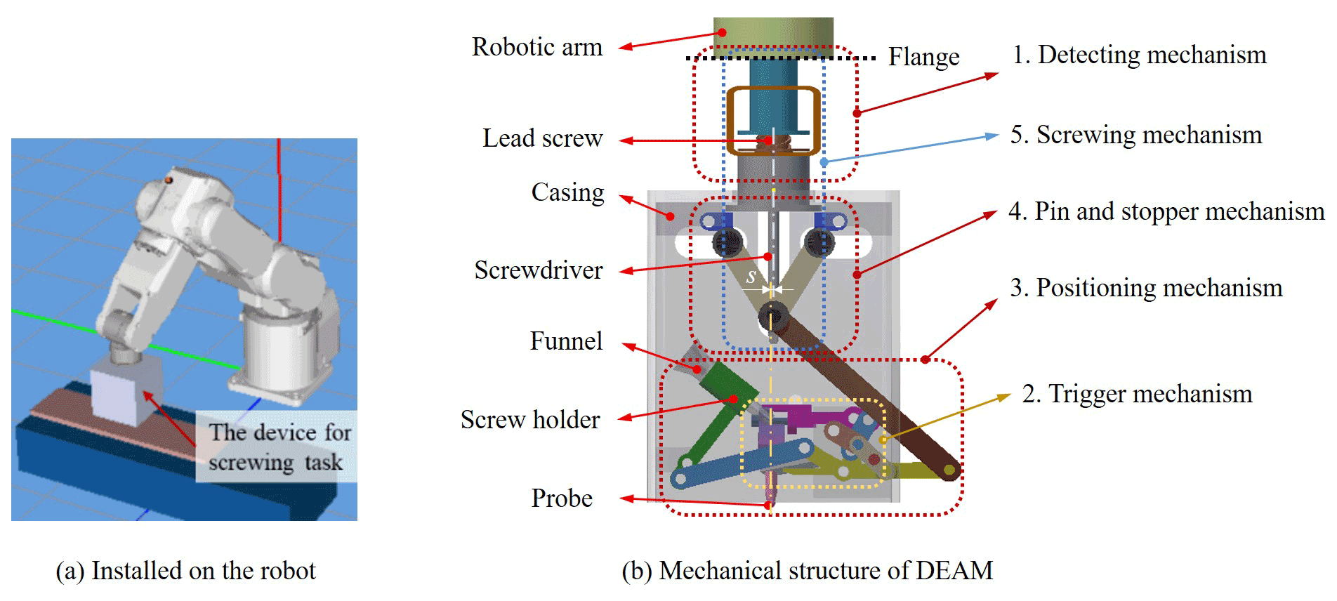
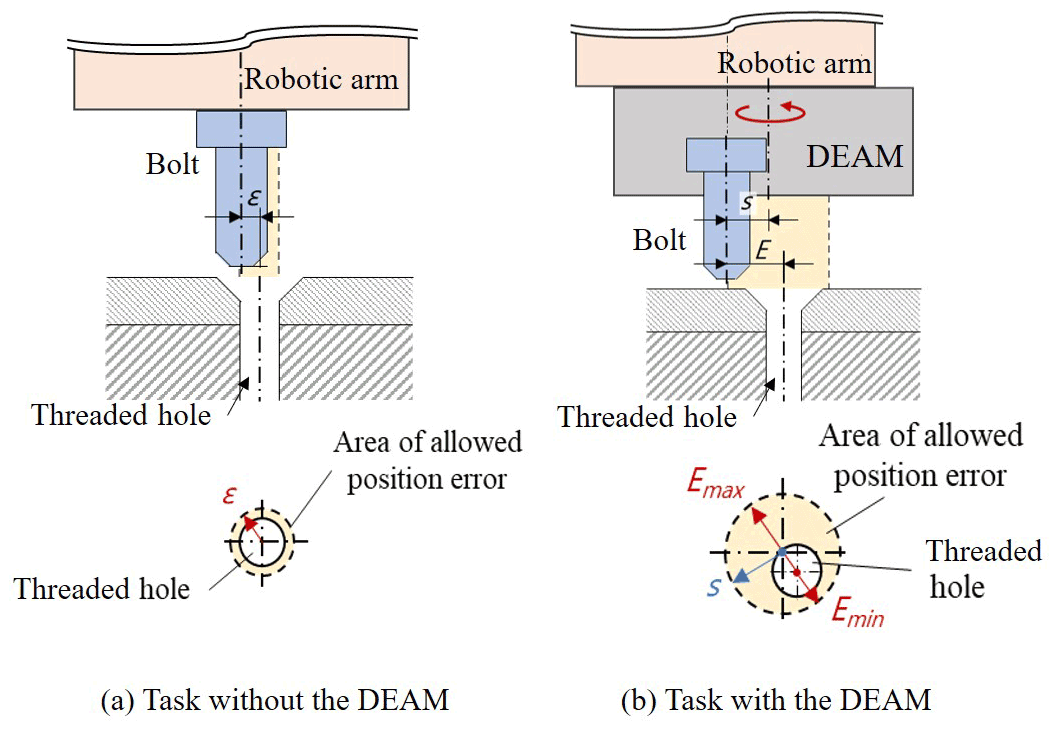
The input motion of the device is provided by the robot arm when it presses downward. As shown in Fig. 1a, the device is attached to the flange of robot arm through a lead screw. Figure 1b shows the structure layout of the device with five mechanisms, namely detecting, trigger, positing, pin-and-stopper, and screwing mechanisms. The original area of the allowed position error ε is shown in Fig. 2, and it can be 1 mm for an M6 screw with a chamfer, for example. By applying the proposed DEAM, there is an offset s between the center line of the leading screw and the probe; therefore, a circle area with radius s is generated as the allowed position error. When the offset s is bigger than the error tolerance ε, then the allowed position error is enlarged. For instance, if s is set as 3 mm, the then maximum of error Emax is 4 mm, and the minimum of error Emin is 2 mm, where Emax means that the vector from the central lines of the leading screw to that of the plunger is parallel to the original error. Emin refers to the case when the two vectors are in opposite direction.
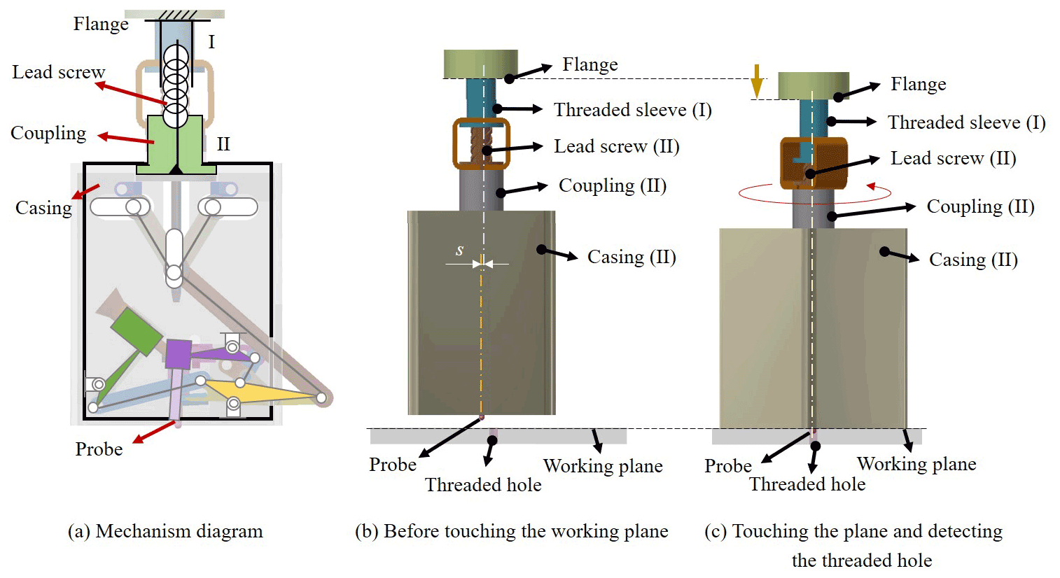
For the first design requirement, a detecting mechanism is composed of a threaded sleeve (link I), a lead screw attached to a coupling and a casing of the device (link II), and a probe at the bottom, as in the mechanism structure shown in Fig. 3a. When the arm goes downward, the device with the probe rotates on the axis of the leading screw. There is a distance s between the central lines of the leading screw and the probe, so the probe moves along a circle with radius s to search for the threaded hole.
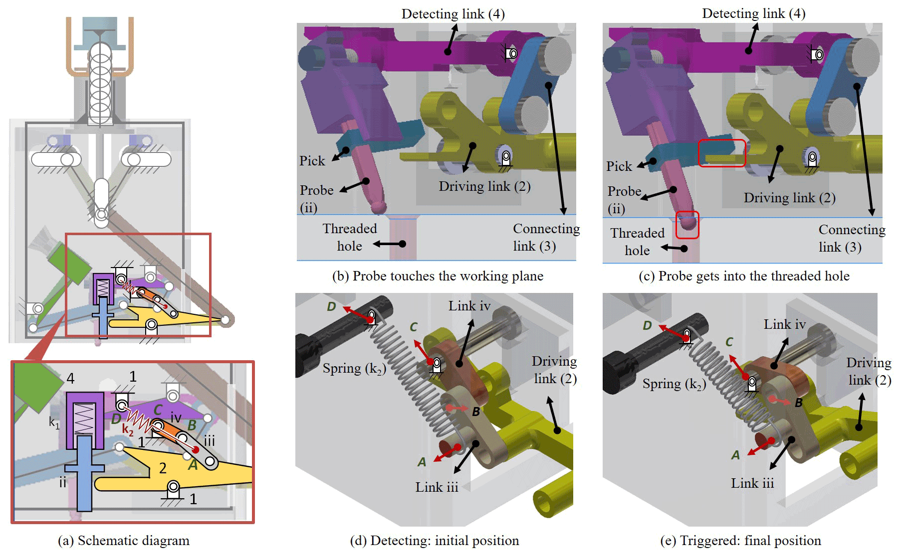
For the second design requirement, the screw-positing mechanism is driven by the trigger mechanism with a plunger, as shown in Fig. 4a. A plunger (link 4) is composed of a cylinder, a compression spring (k1), and a probe with a pick. When the probe reaches the target threaded hole, it moves downward by a small amount, and this small displacement makes the pick achieve the driving link, as Fig. 4b and c show. It is used as a signal that achieves the screw-positioning mechanism. The structure of the trigger mechanism, Fig. 4a, consists of the casing (link 1), a driving link (link 2), and two connecting links (links iii and iv). At the initial position, the four points A, B, C, and D are almost collinear, where the points A and D are the two ends of the spring (k2), B is the revolute joint between links iii and iv, and C is the pivot of link iv. Therefore, the tension spring (k2) has its (almost) largest elastic potential pulling the driving link (link 2) at the initial position, as Fig. 4b and d show. When the probe is ejected downward slightly, Fig. 4c, the driving link is pulled by the tension spring (k2) to reach its final position fast, Fig. 4e, to achieve the screw-positing mechanism and put the screw in the threaded hole. The driving link (link 2) is shared by the trigger mechanism (Fig. 4) and screw-positioning mechanism (Fig. 5). Once the driving link is rotated by the spring (k2) of the trigger mechanism, it provides the input motion of the screw-positioning mechanism, as Fig. 5a and b show. The screw-position mechanism is composed of six links, including the casing (link 1), the driving link (link 2), two connecting links (links 3 and 5), a detecting link with the plunger (link 4), and a link with screw holder (link 6). The final position of the screw attached on link 6 is at the initial position of the probe; therefore, the screw can be positioned at the location where the threaded hole is detected by the probe.
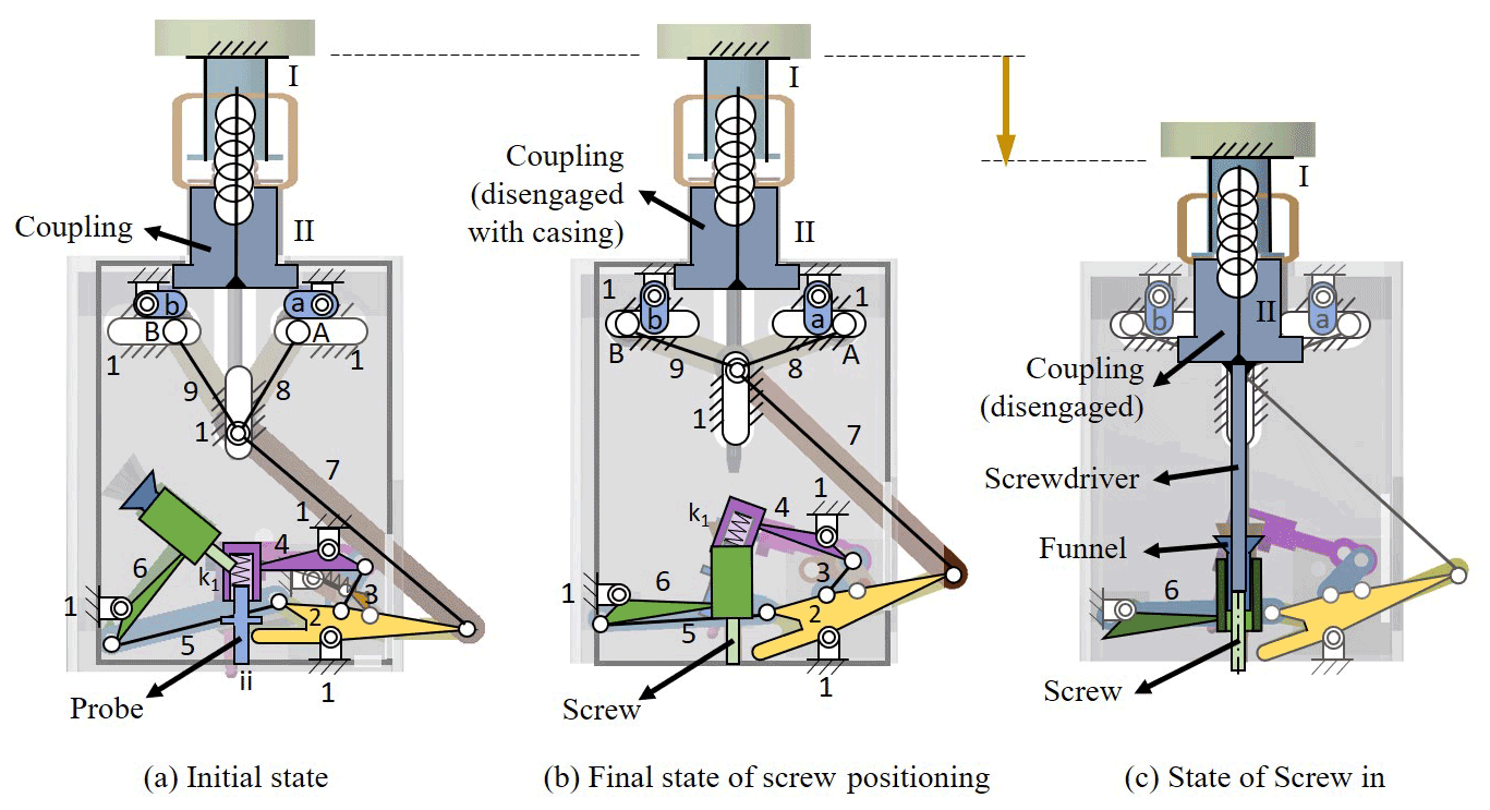
For the third design requirement, a pin-and-stopper mechanism and a screwing mechanism with a screwdriver are equipped under the lead screw with a coupling. As Fig. 5a and b show, a pin-and-stopper mechanism is set at the top of DEAM, including the casing with three slots (link 1), the driving link (link 2), three kinematic links (links 7–9), and two stoppers (links a and b). At the original position (Fig. 5a), the coupling with the lead screw is engaged with the casing of the device, and the stoppers (a and b) are clamped by the pins (A and B) and the coupling, respectively. Once the driving link (line 2) is acted on by the trigger mechanism, it also makes the pins (A and B) move to both sides (Fig. 5b). At the same time, stoppers a and b rotate, and the coupling disengages with the casing by moving downward (Fig. 5c). Then, the coupling switches to transmit the rotation of lead screw to the screwdriver. With the robotic arm moving downward, the screwdriver contacts the screw through the funnel and locks it in the threaded hole. For the fourth requirement, a jig with a specific geometric shape is designed to make all links return to the initial position and put a new screw to the holder.
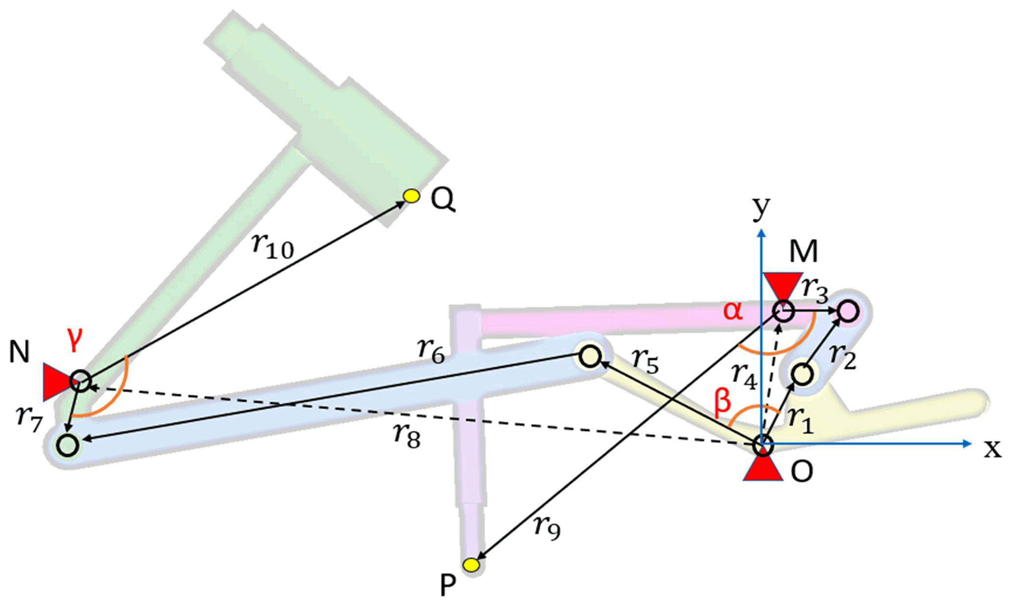
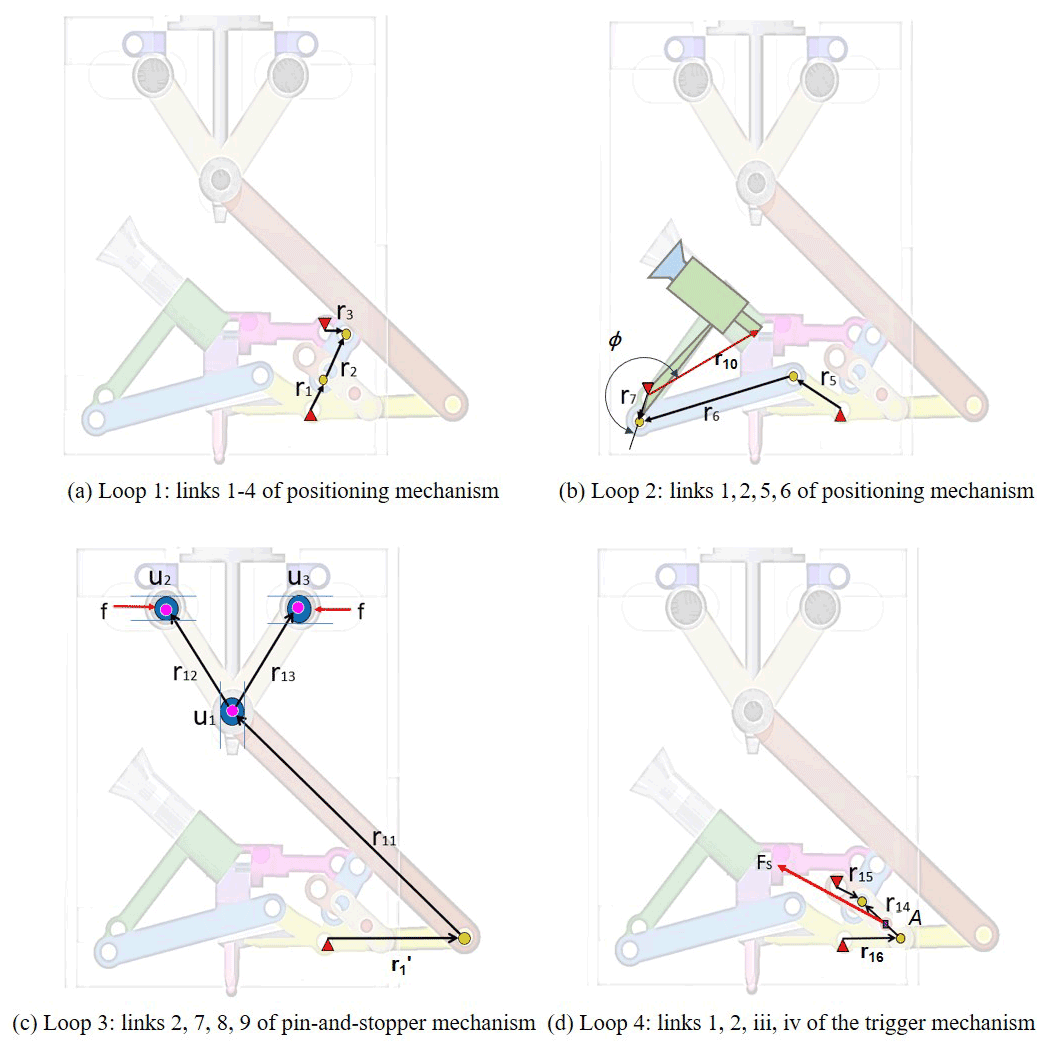
In order to check that the motion of the screw-positioning mechanism can achieve the expected function, the vector loop method is used, as shown in Fig. 6. The mechanism is divided into two independent loops to determine the movement of the plunger and the holder with a screw. The extreme points of the probe and screw holder are labeled with points P and Q, respectively. Therefore, the equations representing each loop are expressed as follows, where θi is defined as the angle between vector ri and the x axis.
For the first loop, Eq. (1) can be extended as follows:
The input and output parameters are θ1 and θ3, respectively. Since the length of the links ri () and the fixed angle θ4 are given, the angular position of the output link θ3 can be determined.
where
Therefore, the initial position of the probe P can be expressed as follows:
where M(Mx,My) is the pivot of the detecting link with the probe, and the angular position θ9 can be expressed as .
For the second loop, the input and output parameters are θ5 and θ7, respectively. The length of the links ri (i= 5–8) and the fixed angle θ8 are given. Similarly, the angular position of the output link θ7 can be determined through Eq. (2) as follows:
where
Since the vector r1 and r5 are the same link, the angular position θ5 can be expressed as .
Moreover, the output of the whole mechanism is the position of the holder with a screw, which is represented by the point Q and the vector r10. The final position of the holder Q can be expressed as follows:
where point N(Nx,Ny) is the pivot of the link with the screw holder, and the angular position θ10 can be expressed as .
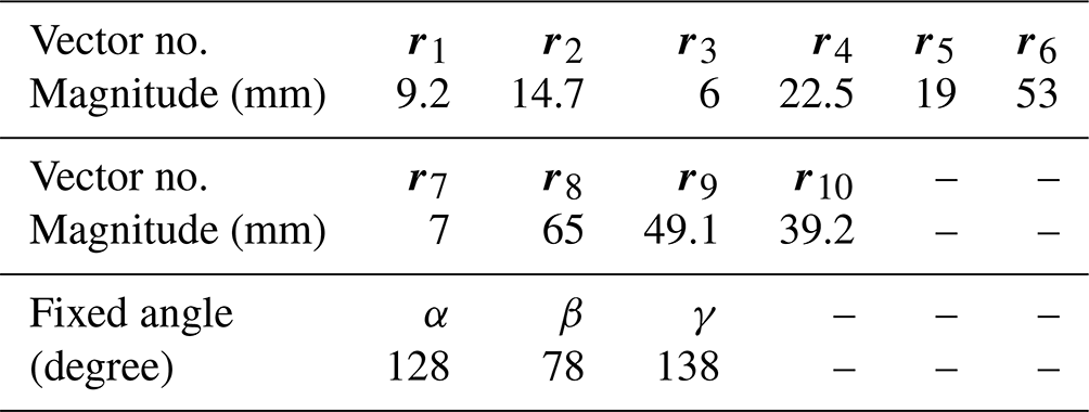
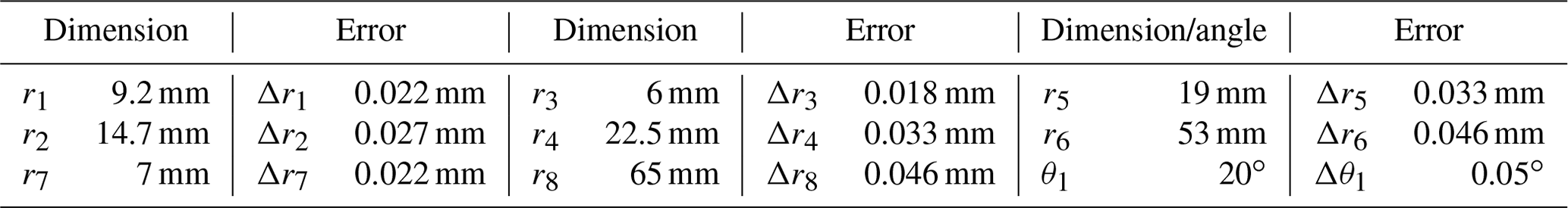
With the consideration of the design specifications, the feasible dimensional parameters of the mechanism are defined, as listed in Table 1. The input motion of this mechanism can be measured as θ1 from 70 to 90∘.
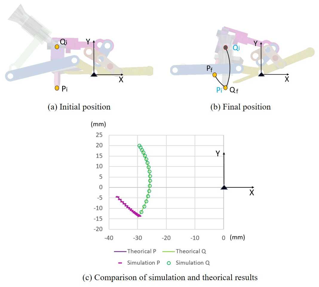
In order to verify the function of the screw-positioning mechanism, the software Inventor is used for building a 3D model for motion simulation. Figure 7 shows the motion trajectory of the points P and Q and the numerical results of both theory and simulation. The initial position of point P (labeled as Pi) is (−29.40, −13.68), and the final position of point Q (labeled as Qf) is (−29.40, −13.29). As the result, the mechanism positions the screw to land at the same coordinate where the probe detected a hole with the error of about smaller than 0.01 mm on the x axis. The error in the y direction is not a prioritized concern in this section since it will be eliminated by the pressure of the manipulator in the screwing task.
Since the actual performance of this device can be affected by the dimensional tolerance of all the linkages, the manufacturing and assembling accuracy requirements for each linkage need to be considered. In this section, the mechanism is divided into two four-bar loops. Both four-bar loops can be verified by substituting two sets of known dimension factors into the set of equations derived from the method proposed in Hsu and Chung (2021) and Choubey and Rao (1987).
There will be a length error (Δr1, Δr2, Δr3, and Δr4) in each link due to manufacturing inaccuracy and input motion error (Δθ1) due to control inaccuracy, and they will cause error Δθ3 in the output angle θ3. Substituting those errors into Eqs. (6)–(8) and can be rewritten as follows:
After simplification (since Δ≈0, sinΔθ3=Δθ3, cosΔθ3=1, and ), the equation of output error Δθ3 can be obtained as follows:
The error equations ΔA, ΔB, and ΔC are derived as follows:
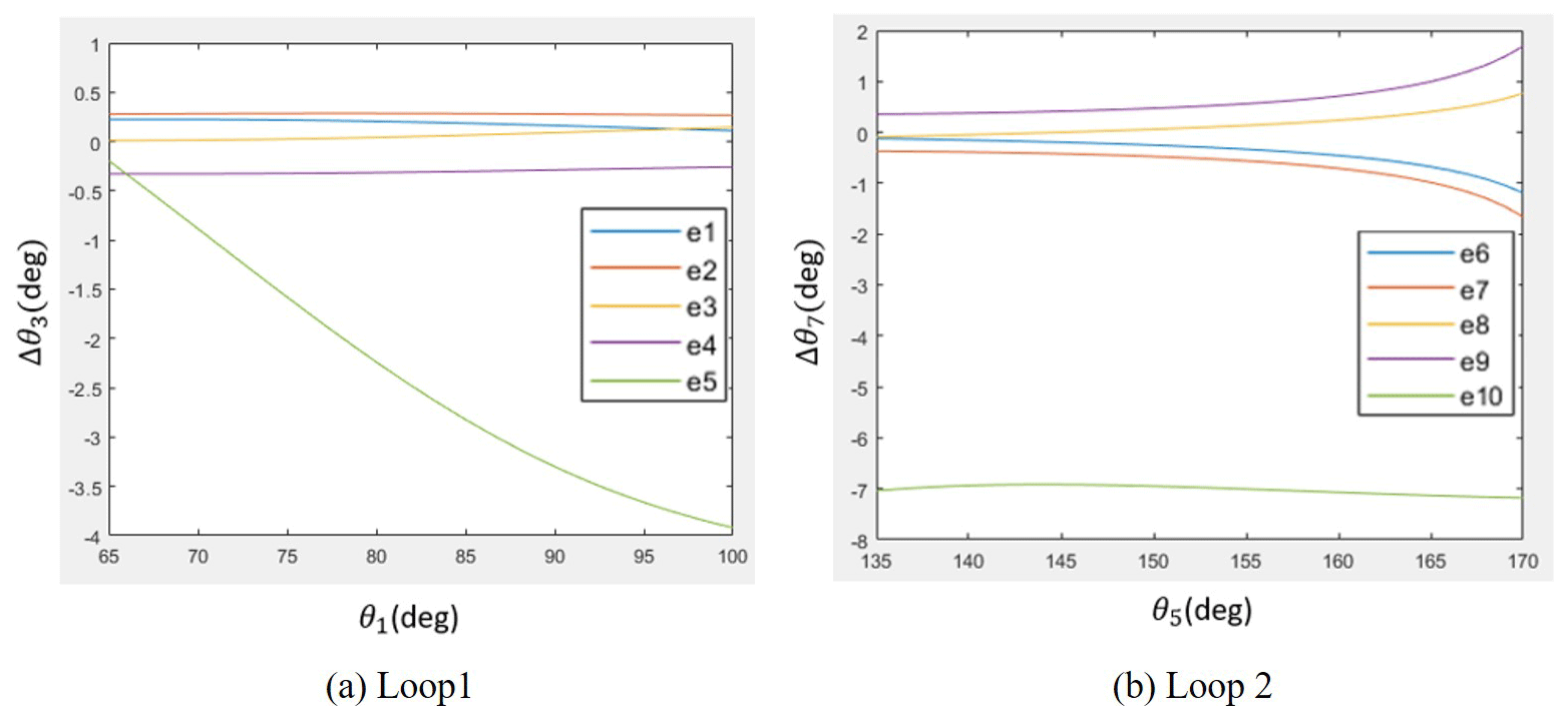
Next, substituting ΔA, ΔB, and ΔC into Eq. (15), the output error Δθ3 caused by each small error existing in the link parameters Δr1, Δr2, Δr3, Δr4, and Δθ1 are considered separately. The errors are set according to IT8 standard as shown in Table 2; hence, five equations of output error e1−e10 with regard to the input angle θ1 can be formulated. Like the numerical result shown in Fig. 8, the maximum output error caused by the input angle error θ1 is about −4 ∘ for loop 1 and −7 ∘ for loop 2. The output error caused by the length errors are within ± 0.5 ∘ for loop 1 and smaller than ± 2 ∘ for loop 2. This result indicates that the output error is by far more sensitive to the input angle error Δθ1 than it is to all the length errors.
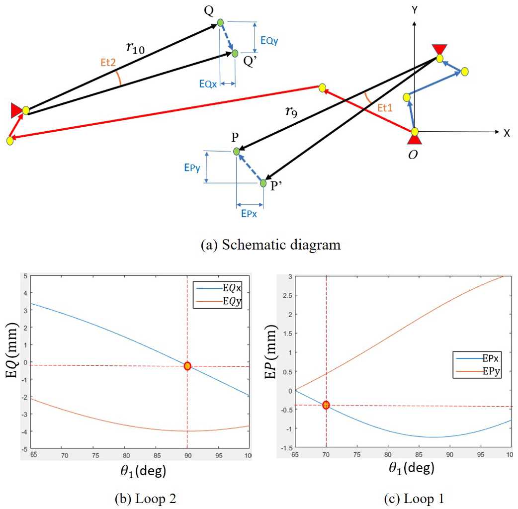
The output angle errors e1−e5 in loop 1 are summed up as E1, and e6−e10 in loop 2 are summed up as E2, where we substitute E1 and E2 into Eqs. (9) and (14), respectively. The position errors of points P and Q with regard to the input angle θ1 can be measured as EP and EQ, respectively.
The position output error of point P does not affect the screw-positioning and locking performance, since it only needs to be removed away from the hole before point Q arrives. As shown in Fig. 9, when θ1=70∘ (initial position), the output position error of point P is about −0.4 mm on the x axis. When θ1=90∘ (final position), the output position error of point Q is about −0.2 mm on the x axis.
Combining the two errors, the result shows that the screw-positioning error is about 0.2 mm, which is still smaller than the radius of M6 screw positioning. This is the extreme case obtained, assuming all the length errors and input angle errors are maximum and in the same direction. This kind of extreme case is unlikely to occur, since the length errors and input angle errors are usually in different directions.
During the operation of this device, besides the downward force of the robotic arm being converted into a rotary motion through the lead screw, all the other mechanism motions are driven by the tension spring (k2). In order to make sure that the device operates as designed, the specification of the spring should be selected according to the force analysis. Since the movement of the mechanism in the device starts at rest, the energy method is used to analyze the static force of the planar mechanism to provide reference data for the selection of springs in subsequent prototype.
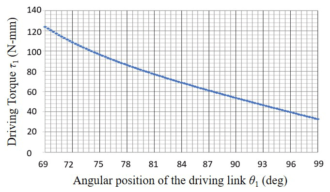
The screw-positioning mechanism proposed in this study is driven by a spring of the trigger mechanism, as shown in Fig. 4, in which each joint of a grounded input link simultaneously drives the movement of other links. The four joints of the input link are incident to four independent loops with the vectors r1, r5, , and r16, respectively. The motion and force characteristics are analyzed separately in each loop to obtain the sum of the required input torque as shown in Fig. 10, and then the appropriate spring force required to drive the linkage (Fs) can be determined, where , . The friction forces provided by the coupling are also considered during the simulation, since they are much bigger than other resistance forces.
The angular velocity of the links ω2−ω15 and the linear velocity of the pins sliding in the slots can be listed as functions of the input angular velocity ω1 as follows:
where θ1, θ5, θ10, and θ16 are located at the driving links; therefore, each difference between these four angles is constant.
With the angular velocity of each link, the velocity of the mass centers vGi (i= 1–16) can be calculated, as listed in Eqs. (25)–(36).
The torque required to drive the linkage at the beginning position can be calculated by static force analysis from the following:
By prototype testing, the force required to rotate the device by pressing down on the flange is 19.6 N, and the friction coefficient between the pin and the slot of the casing is 0.1; therefore, the friction force f is about 0.98 N for each pin. Moreover, for the screw in mechanism shown in Fig. 5c, the screwdriver is lowered to the screw for about 0.4 s; that is, the input link of the screw-positioning mechanism has to complete the action from initial to the final positions (θ1 from 70 to 90∘) within 0.4 s. The minimum required ω1=0.87 rad s−1, taking ω1=1 rad s−1 with the input angular velocity greater than the minimum requirement as a numerical example. Dimensions of the vectors and the mass of links are listed in Tables 2 and 3, respectively. The spring force can be determined from Eq. (37) in that FS=13.5 N.
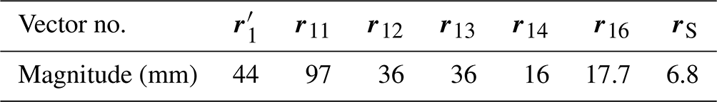

The input link r1 is split into r1, r5, , and r16 during the calculation of velocities in order to simplify the process, and the mass center rG1 and the mass of r1 are applied only once in the force calculation. During simulation, the torque required to drive the mechanism with regard to θ1 is as shown in Fig. 11 and is about 120 N mm at the beginning, which is close to the torque obtained through the theoretical analysis in Eq. (37). Based on the analysis result, a spring with a stiffness of 1 N mm−1 is selected, which is extended by 15 mm at the beginning position providing a force of 13.5 N, which is bigger than theoretical spring force FS needed to drive the linkage.

Prototype testing is carried out with five steps, as shown in Fig. 12. An M6 hexagon socket cap screw is used in this testing, and the target threaded hole is located on a smooth working plane. Before the device contacts the working plane, all of the links stay at the balancing position, and the plunger is set a little bit lower than the bottom of outer case, as shown in Fig. 12a. First, when the device is placed on the surface of the working plane, the position of plunger is close to the target threaded hole with an error E, as shown in Fig. 12b. With the reacting force from the working plane, the plunger is lifted slightly. Second, the flange of the robot presses downward, and the device rotates through the transmission of the leading screw, Fig. 12c. The plunger slides along a curved path on the working plane but does not cause any movement of the mechanisms inside the device. Third, once the plunger reaches the hole, without the reaction force from the plane, the plunger goes downward to move inside the hole. The inertia of this motion acts on the trigger mechanism, the links of clutch mechanism are activated, and therefore the outer case stops rotating (Fig. 12d). Moreover, the screw-positioning mechanism is also driven by the spring of trigger mechanism. The screw is placed in the hole by the screw holder. Finally, the coupling with a screwdriver goes down until it reaches the funnel on the screw holder. Since the outer case is fixed by the clutch mechanism, the rotation of leading screw drives the coupling directly to screw in the hole (Fig. 12e). The prototype was tested repeatedly with misalignment from 0 mm (the probe goes into the hole originally) to 4 mm. As the result, when the position error s is less than 3 mm, the whole motion procedure and proposed functions could be completed in more than 80 % of the testing. In the case of failed test, the device could detect the position of the threaded hole, but the motion of screw-positioning was not stable. Besides, when the misalignment increases to more than 3 mm, the probability of successful screw-positioning drops below 30 %. Compared to the situation of the screwing task without DEAM, the allowable misalignment for the M6 screw is measured at about 0.5 mm. Therefore, the feasibility of the proposed design concept is verified.
In order to lower the frequency of suspending and calibrating the robot manipulator, an innovative device for enlarging the allowed position error is presented in this paper, including the functions of hole detecting, screw positioning, and screw locking.
It is cheaper than the vision system and easier to assemble than most RCC devices. In total, five mechanisms are proposed to achieve the functions, including the detecting mechanism with a lead screw engaged to the casing of the device, a four-bar trigger mechanism with a spring, a six-bar screw-positioning linkage with a plunger and a screw holder, a pin-and-stopper linkage with a coupling that plays a rule of a clutch, and the screw-in mechanism with a screwdriver. Kinematic analysis of the critical screw-positioning mechanism is made to verify its function and check the effort of tolerance. To sum up, this mechanism is able to place the screw at the position where the plunger reached a threaded hole with an error smaller than 0.2 mm in the horizontal direction. Although the design can be improved through dimensional synthesis, the feasibility of the mechanism is checked to execute the screwing task. The sensitivity with respect to dimensional errors and input angle errors have been analyzed to determine the manufacturing accuracy for the prototype. Force analysis has been conducted to select the proper spring to drive the mechanism. Since the results have been verified through prototype testing with M6 screw, the allowable position error can be enlarged to 3 mm by this innovative design, which is enlarged by about 6 times than the original task without DEAM. This device has the potential for being widely applied in production lines to lower the cost after improving its operational stability.
All software code and data included in this study are available upon request to the corresponding author.
YHC conceived the study conception and design procedure. HTK made a kinematic analysis, collected the data, and interpreted the results.
The contact author has declared that neither of the authors has any competing interests.
Publisher’s note: Copernicus Publications remains neutral with regard to jurisdictional claims in published maps and institutional affiliations.
The authors are grateful to the Ministry of Science and Technology (Taipei, Taiwan; grant no. MOST 108-2218-E-011-031-MY2), for the support of this work.
This research has been supported by the Ministry of Science and Technology, Taiwan (grant no. MOST 108-2218-E-011-031-MY2).
This paper was edited by Daniel Condurache and reviewed by two anonymous referees.
Cai, Y., Gu, H., Li, C., and Liu, H. S.: Easy industrial robot cell coordinates calibration with touch panel, Science Direct on Robotics and Computer-Integrated Manufacturing, 50, 276–285, 2018.
Choubey, M. and Rao, A. C.: Synthesizing Linkages with Minimal Structural and Mechanical Error Based upon Tolerance Allocation, Mech. Mach. Theory, 17, 91–97, 1981.
Ginani, L. S. and Motta, J. M. S. T.: Theoretical and practical aspects of robot calibration with experimental verification, J. Braz. Soc. Mech. Sci., 33, 15–21, 2011.
Hsu, K. L. and Chung, J. Y.: A Modular Method for Mechanical Error Analysis of Planar Linkages Composed of Class II Assur Group Kinematic Chains, ASME Journal of Mechanisms Robotics, 14, 014503, https://doi.org/10.1115/1.4051703, 2021.
Kim, U., Park, D. I., Jo, G., Jeong, H., Kim, H. S., Song, S. H., and Park, C.: Displacement Sensor Integrated Into a Remote Center Compliance Device for a Robotic Assembly, IEEE Access, 9, 43192–43201, 2021.
Lai, L. J. and Zhu, Z. N.: Modeling and Analysis of a Compliance Model and Rotational Precision for a Class of Remote Center Compliance Mechanisms, Appl. Sci, 6, 388, https://doi.org/10.3390/app6120388, 2016.
Lee, S. C.: Development of a new variable remote center compliance (VRCC) with modified elastomer shear pad (ESP) for robot assembly, IEEE T. Autom. Sci. Eng., 2, 193–197, 2005.
Li, A., Wang, W., and Wu, D.: Calibration of a robot-based measuring system, in: IEEE International Conference on Robotics and Biomimetics (ROBIO), Guilin, China, 19–23 December 2009, 1361–1364, https://doi.org/10.1109/ROBIO.2009.5420864, 2009.
Liu, Y., Xi, N., Zhao, J., Nieves-Rivera, E., Jia, Y., Gao, B., and Lu, J.: Development and sensitivity analysis of a portable calibration system for joint offset of industrial robot, in: 2009 IEEE/RSJ International Conference on Intelligent Robots and Systems, St. Louis, MO, 10–15 October 2009, 3838–3843, https://doi.org/10.1109/IROS.2009.5353951, 2009.
Nubiola, A. and Bonev, L. A.: Absolute robot calibration with a single telescoping ballbar, Precis. Eng., 38, 472–480, 2014.
Omodei, A., Legnani, G., and Adamini, R.: Calibration of a measuring robot: Experimental results on a 5 DOF structure, J. Robotic Syst., 18, 237–250, 2001.
Roth, Z., Mooring, B., and Ravani, B.: An overview of robot calibration, IEEE Journal on Robotics and Automation, 3, 377–385, 1987.
Veitschegger, W. K. and Wu, C. H.: Robot calibration and compensation, IEEE Journal on Robotics and Automation, 4, 643–656, 1988.
Wu, C. Y.: Rotation angle of the robot arm calibration system and calibration method, Master Dissertation, Department of Mechanical Engineering, National Chung Hsing University, Taichung, https://hdl.handle.net/11296/n6c5fb (last access: 12 December 2021), 2004.
Zhong, X. L. and Lewis, J. M.: A new method for autonomous robot calibration, in: Proceedings of 1995 IEEE International Conference on Robotics and Automation, Nagoya, Japan, 21–27 May 1995, 2, 1790–1795, https://doi.org/10.1109/ROBOT.1995.525529, 1995.
- Abstract
- Introduction
- Design concept
- Motion analysis of the screw-positioning mechanism
- Simulation and numerical results
- Sensitivity analysis of the screw-positioning mechanism
- Force analysis
- Prototype testing
- Conclusions
- Code and data availability
- Author contributions
- Competing interests
- Disclaimer
- Acknowledgements
- Financial support
- Review statement
- References