the Creative Commons Attribution 4.0 License.
the Creative Commons Attribution 4.0 License.
 | 05 Aug 2022
Design and analysis of a hollow-ring permanent magnet brake for robot joints
Ruoyu Tan
Jieji Zheng
Bin Yu
Baoyu Li
Dapeng Fan
Xin Xie
An electromagnetic brake is the key basic component to ensure the safety of robot joints. The conventional electromagnetic brake mostly uses a set of springs to provide braking force and solenoid power to provide a recovery force, which makes this kind of brake with large thickness and small braking torque that is not conducive to the application in light and small joint components. In many design processes, unclear understanding of the machine-electric-magnetic coupling characteristics leads to relatively simple theoretical models and inaccurate theoretical results, which do not provide more help for subsequent designs. In this paper, a hollow-ring type permanent magnetic power-loss protection brake, integrated inside a joint assembly, is designed. The brake uses rare earth Nd–Fe–B permanent magnets to provide braking suction instead of ordinary spring packs, and achieves motion guidance and braking torque transmission by means of leaf spring. Combined with the deformation model of the leaf spring and the magnetic circuit models of the brake under the power-on and power-off conditions, the overall coupling dynamics model of the brake is established. The theoretical results are compared through finite-element software, and a prototype is produced for experimental testing. Finally, the accuracy and validity of the theoretical model are verified, providing a theoretical and experimental basis for the design of this type of brake.
- Article
(3996 KB) - Full-text XML
- BibTeX
- EndNote


In mechanical joints, the brake is the main component to ensure the safety of the equipment. Its function is to ensure that the mechanical joint itself and the end load do not collide unpredictably when the mechanical joint loses power or control, and to maintain the position and attitude of the mechanical joint when it is not working. Whether it is a large robotic arm used on the International Space Station (NASA's Canadarm2) (Gibbs and Office, 2002; Sallaberger, 1997), Japan's Experiment Module Robot System (JEMRMS; Matsueda et al., 2002) and the European Robotic Arm (ERA; Verhoeven, 1999); a small robotic arm used for space experiments and maintenance (Italy's SPIDER, Mugnuolo et al., 1998, and EUROPA, Mugnuolo et al., 1999, Europe's DEXARM, Magnani et al., 2006); or a domestically designed space robotic arm (The robotic arm system of Beijing University of Posts and Telecommunications, Shao et al., 2006, and Harbin Institute of Technology's space robot system, Cheng et al., 2017), the joints are equipped with brakes to ensure the safety of the joints and the equipment.
The two types of brakes that are conventionally used in mechanical joints, are gear pin brakes and friction disc brakes. The gear pin brake is a simple and low-cost construction, with a solenoid driving the pin in contact with the chuck. However, in robotic arm applications, there is a holding gap problem and a certain residual torque. In the brake release process, special control logic is required to ensure that the brake is released under load. Friction disc brakes are the traditional solution and are usually driven by electromagnetic force (Jin et al., 2019).
Friction disc brakes have received extensive attention in recent years and many studies have been carried out on these brakes by companies or institutions at home and abroad. The Mayr company has developed an electromagnetic friction brake, which uses spring force to generate the braking torque. When the arm is in normal operation, the solenoid is energised. Under the electromagnetic suction, the brake discs overcome the spring elasticity to separate from the brake pads, at which point no braking torque is generated. When braking is required, the solenoid coil is de-energised and the brake discs meet the wear-resistant brake housing by spring force, thus generating a braking torque. The brake used in the European Space Agency's ERA uses eight springs to generate the braking torque, which varies between 0.7 and 1.1 N m. The friction material is ceramic and the friction plate is based on AISI 420 stainless steel, to which a thin film of chromium oxide (Cr2O3) is applied using the thermal spray method. The wires come out along the outside of the brake and does not use a hollo-ring construction. The German Aerospace Centre (DLR) has designed a lightweight robotic arm. Initially, a piezoelectric brake was used, which was effective and weighed only 70 g, but its braking performance deteriorated under certain humidity conditions. Therefore, a conventional electromagnetic spring brake solution was adopted (Hirzinger et al., 2001). Yasa et al. (2014) have designed a brake inside a robot joint, which provides braking force via two springs. The electromagnetic suction generated by energising the coil separates the friction disc from the brake housing. The article presents a simple analysis and simulation of the proposed brake in terms of mechanical, electrical, and thermal aspects, and finally verifies the theoretical and finite-element calculation results through experiments. Kumar et al. (2017) designed a permanent magnet electromagnetic brake for an aerospace vehicle. This brake uses a spring to provide the braking force, and the electromagnetic force generated by the solenoid overcomes the spring force to draw back the brake disc. The brake disc is then locked on the brake housing by a permanent magnet embedded in the brake, allowing the motor to operate normally. When braking is required, the solenoid is energised in the opposite direction to counteract the permanent magnetic force (FPM). The spring force pushes the brake disc out again to achieve braking. Compared to conventional electromagnetic brakes, this brake improves the energy efficiency of the system by consuming power only during switching time. In addition, the article presents a simple analysis and simulation of the entire brake, and finally verifies it through experiments, which is a guide to the design of this type of brake. Harbin Institute of Technology has designed a brake with a double-sided disc friction brake. The brake relies on spring force as the braking force and the friction torque is provided by two annular friction plates and a cylindrical friction column. One end of the friction column is placed between the two friction plates and the other end is connected to the rotating shaft. The rotating shaft drives the friction column to rotate with it. When braking, the solenoid is de-energised and one side of the friction plate squeezes the friction column under the action of spring force to meet the other side of the friction plate. The two friction plates together with the intervening friction column generate the braking torque. When the brake is not working, the solenoid is energised to generate electromagnetic suction to pull back one side of the friction plate, causing the friction plate, the friction column, and the other friction plate to separate, and the braking torque then disappears. The brake is experimentally measured to have a braking torque of around 0.5 N m and a weight of around 270 g (Li, 2015). As can be seen from the above examples, conventional electromagnetic brakes rely on a spring set to generate the braking torque, and these brakes usually have the disadvantages of being thick, having a small braking torque and being difficult to assemble and maintain.
Due to the use of spring packs to provide braking force, the braking force generated by the spring packs needs to be overcome all the time during non-braking conditions. This requires the coils to be continuously fed with a high current, since this type of brake always needs to be maintained at a high-power level during operation. In order to install the spring packs, these brakes usually have the disadvantages of being thick, having a small braking torque and being difficult to assemble and maintain, which leads to it being less suitable for use in light mechanical joints.
In this paper, a hollow-ring permanent magnet brake integrated into the robot joint is proposed. In contrast to conventional spring electromagnetic brakes, this brake uses rare earth Nd–Fe–B to provide braking suction instead of conventional spring packs. In the braking state, the brake armature is suctioned onto the brake housing. A leaf spring is used as the resetting element for the brake armature. This design allows the brake to require much less axial space, which not only reduces the overall axial dimensions of the mechanical joint, but also provides more than 1.5 times the braking torque for the same volume as the conventional electromagnetic-spring friction braking principle. When the coil is energised, a reverse electromagnetic force is generated to counteract the braking suction, the leaf spring provides the return force and only a very small deflection stroke is generated during the suction and release process, ensuring that the brake armature is released quickly and accurately in the braking position. Compared to conventional wire routing ways, the hollow-ring routing avoids the exposure of conductors to electromagnetic radiation and the disadvantage of having to leave a margin at each joint.
Furthermore, a coupled dynamics model of the proposed brake is developed from machine-electric-magnetic aspects. The leaf spring is firstly modelled and the expressions for the deformation angle and deflection are derived. The equivalent magnetic circuits of the brake are modelled under power-on and power-off states, respectively. The variation of the permanent and electromagnetic fields inside the structure and the magnetic flux trend are analysed. A theoretical model is built for the variation of magnetic flux and flux density in the working air gap with the movement of the braking armature under two states. Expressions for the braking suction on the braking armature in the sucking and separation process are derived from the energy storage perspective.
The 3D model of the brake is simulated by means of the finite-element software, and some key parameters affecting the performance of the brake are calculated and compared with the results of the established theoretical models. Finally, the accuracy and validity of the theoretical models are verified through experiments.
Figure 1a shows a partial cross-sectional view of the mechanical joint. The brake body is mounted on the mounting base in the joint and the brake armature is connected to the motor rotor through a leaf ring, which transmits axial displacement and prevents circumferential rotation. The permanent magnet ring is embedded in the body of the brake and provides permanent magnetic suction for the brake. When the motor is powered off, the brake body and the brake armature are absorbed to achieve a holding brake on the motor rotor and lock the motor. When the motor is in powered on, the coil of the brake is energised to produce an electromagnetic force to counteract the permanent magnetic suction and the brake body is separated from the brake armature, which rotates with the motor rotor. Figure 1b shows an exploded view of the brake.
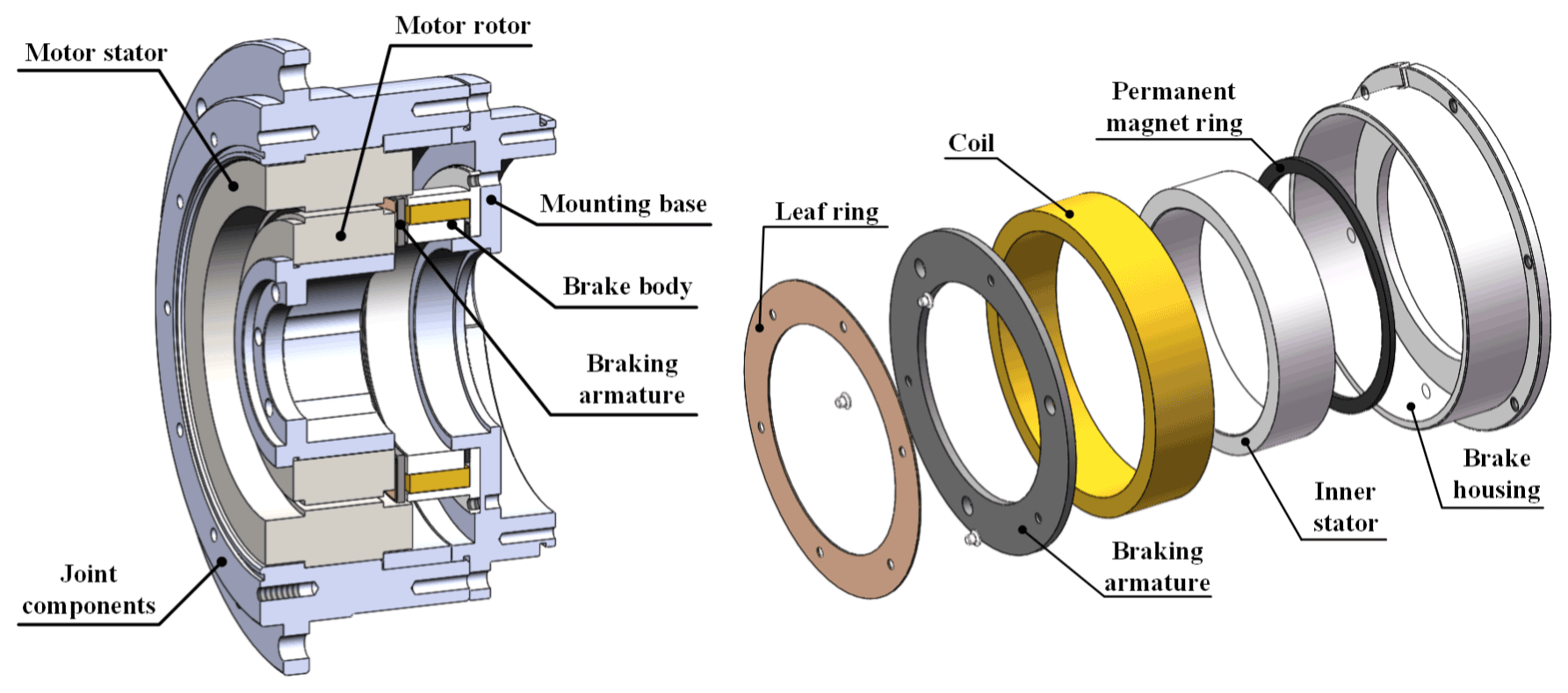
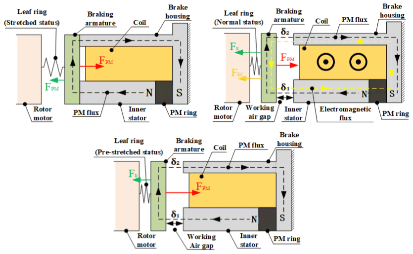
Figure 2a shows the magnetic circuit of the brake in the power-off suction state. The permanent magnet ring always generates a permanent magnetic flux, which together with the brake armature, the brake housing and the inner stator form a permanent magnetic circuit. When the motor is powered off, only permanent magnet fluxes are generated by the permanent magnets in the circuit. The permanent magnetic force (FPM) overcomes the elasticity of the flexible ring to keep the brake armature attached to the brake housing and the inner stator. The structural characteristics of the flexible ring itself result in a relatively low stiffness in the axial direction and relatively high stiffness in the circumferential direction of rotation, thus providing support and guidance for the axial movement of the brake armature and rotational resistance for the circumferential movement.
Figure 2b shows that in the power-on state of the motor, after the coil is energised, an electromagnetic flux equal in magnitude to the permanent magnet flux and opposite in direction is generated in the structural circuit as a counteracting flux. The total magnetic flux in the working air gaps is reduced, the suction force is weakened, the brake armature is pulled back to the working position by the restoring force of the flexible ring, and the brake armature rotates with the rotation of the motor.
Figure 2c shows the situation when the motor suddenly loses power and goes from the operating state to the braking state. At this point, the brake is simultaneously de-energised, the electromagnetic flux disappears and the structure and working air gap are filled with permanent magnetic flux again. The brake armature is re-activated by the suction force and overcomes the elasticity of the leaf spring itself and is then absorbed by the brake housing and the inner stator, completing the power-loss braking action.
3.1 Modelling of leaf spring
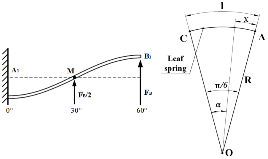
The leaf spring connects the brake armature and the motor rotor by alternating wave crests and wave troughs, and the connection point is equally symmetrical at 360∘ n−1, where n refers to the number of the fixed points. For simplicity of analysis, the ring piece was taken at 360∘ n−1 and n= three equally divided parts for analysis. The specific structure is shown in Fig. 3a. The six connection points are evenly distributed on the leaf spring as shown, with A1, A2 and A3 connected to the rotor and B1, B2 and B3 connected to the brake armature. When the brake armature is subjected to the axial suction of the permanent magnet, it acts equally on points B1, B2 and B3 to deform the leaf ring at the same time.

From the mechanics of materials, the 120∘ ring segment can be equivalent to a typical antisymmetric beam for analysis, as shown in Fig. 3b. Consider A1 and A2 as fixed points, and B1 as one of the connection points connected on the brake armature. The brake armature is driven by the suction force F to deform the leaf ring axially, which is equivalent to the suction acting at point B1 (mid-point of the beam in the diagram). If the section from 0 to 60∘ of the deformed beams is taken directly as a typical cantilever beam structure for analysis, the boundary condition restriction of zero deformation at the A2 fixed point is ignored.
With a small size, small axial deformation and uniform deformation of the leaf spring, the superposition method can be used to first obtain the maximum deformation angle and deflection of the leaf spring in the interval from A1 to point M (0–30∘ section) and then the maximum deformation angle and deflection in the interval from M to B1 (30–60∘) by means of the deformation antisymmetric principle, as shown in Fig. 4a.
Under suction, in the range of 120∘, the deformation of the leaf spring at each point can be calculated by direct integration according to the approximation differential equations for deflection lines of beams:
where M(x) is the bending moment at each point of the leaf ring, E is the modulus of elasticity of the ring material, I is the moment of inertia of the section of the ring, and C and D are determined by the boundary support conditions of the leaf ring.
According to the leaf spring structure, the boundary support conditions are
where θ(x) is the angle of deformation of the leaf ring, in the direction parallel to the axial direction, w(x) is the deflection of the leaf ring, in the direction parallel to the axial direction and A is the fixed point of the ring piece, with a deformation of 0.
In the range 0–60∘, the leaf spring structure is shown in Fig. 4b, and M can be expressed as
where FB is the suction force at point B, F is the total suction force from the permanent magnet and . R is the distance from FB to the centre of the circle of the leaf spring, α is the angle corresponding to section 0 to of the leaf spring, and x is the length of the arc corresponding to .
When x=0, C and D can be obtained as follows:
The final deformation angle and deflection models of the leaf ring are
The deformation angle and maximum deflection of the leaf spring along the axial direction in the range of 0–30∘ under the suction of the permanent magnet can be obtained. According to the principle of structural antisymmetric and symmetric deformation, the deformation angle and maximum deflection of the entire flexible ring sheet along the axial direction are further obtained from 30 to 60 and 60 to 120∘.
3.2 Modelling of magnetic circuit
3.2.1 Modelling of the magnetic circuit in power-off state
According to the actual working conditions, the power-off state is divided into just power-off state and maintained power-off state for analysis. The power-off state refers to the moment when the brake changes from the working power-on state to the power-off state. At this time, only the permanent magnetic flux generated by the permanent magnet ring remains inside the structure, but there is still a working air gap between the brake armature and the braking body. The leaf spring is still in a stretched state, as shown in Fig. 2c. The brake armature is subjected to permanent magnetic suction. When the suction force is greater than the elastic force of the flexible ring piece, the brake armature is sucked onto the brake body. At this time, the working air gap is reduced to 0, and the device enters the suction state, as shown in Fig. 2a. Due to the simultaneous axial force at the three points (B1, B2, B3) of the leaf spring, the working air gap δ1 is always equal to δ2. From the analysis above, the equivalent magnetic circuit of the process is established.
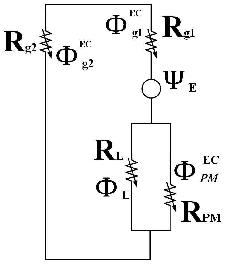
As shown in Fig. 5, the magnetomotive force of the permanent magnet ring in the figure is expressed as ΨPM, the internal resistance is expressed as RPM, the generated permanent magnetic flux is expressed as φPM, and the magnetic flux passing through the working air gap can be expressed as , where . The leakage magnetism in the structure can be equivalently expressed as leakage magneto-resistance, denoted as RL. The materials of the inner stator, brake housing and brake armature are soft magnetic alloys. Compared with permanent magnets and air, the relative magnetic permeability of soft magnetic alloys is much higher than that of permanent magnets and air (a million times). Therefore, the reluctance of stator, brake housing and brake armature can be ignored in the model.
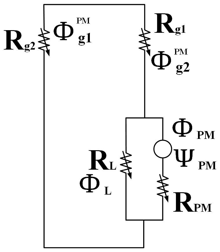
According to Kirchhoff's law
Combining the equivalent magnetic circuit model with the magnetic circuit theory,
where ΨPM is the magnetomotive force of the permanent magnet ring in the magnetic circuit, φPM is the total magnetic flux generated by the permanent magnet ring, RPM is the internal resistance of the permanent magnet ring, RL is the leakage magnetic resistance, φL is the leakage magnetic flux, Rg1 is the air reluctance of the working air gap between the inner stator and the brake armature, Rg2 is the air reluctance of the working air gap between the brake housing and the brake armature, φg is the magnetic flux between the working air gap, and σ is the magnetic flux leakage coefficient, which is usually an empirical value and varies from 1 to 10, depending on the magnetic circuit in the structure.
From the Eqs. (9), (10), (17), the leakage reluctance and the magnetic flux in the working air gap can be expressed as
The magnetic resistance of the working air gaps δ1 and δ2 can be expressed as
where Br is the residual magnetisation of the permanent magnet ring, LPM is the thickness of the permanent magnet ring, u0 is the relative permeability in vacuum, ur is the relative permeability of the permanent magnet ring, APM is the cross-sectional area of the permanent magnet ring, δ0 is the initial working air gap, δ is the distance that the brake armature moves in the working air gaps, Ag1 is the area corresponding to the area between the inner stator and the brake armature, and Ag2 is the area corresponding to the area between the brake housing and the brake armature.
Combining the electromagnetic theory and substituting Eqs. (12), (13) into Eq. (11) gives an expression for the magnetic flux in the working air gaps:
From the above equations, the magnetic flux density between working air gap δ1 and working air gap δ2 can respectively be expressed as follows:
3.2.2 Modelling of the magnetic circuit in power-on state
When the brake is energised, the coil generates an electromagnetic flux inside the inner stator, in the opposite direction to the permanent flux, which is used to counteract the permanent flux, as shown in Fig. 2b. Based on the magnetic path in the structure, an equivalent magnetic circuit is created (see Fig. 6).
The electromagnetic force of the energised coil is denoted as ΨE. The magnetic flux through the working air gap can be expressed as (). Magnetic flux leakage can be expressed as magnetic flux leakage reluctance, denoted as RL. The reluctance of the inner stator, brake housing and brake armature is ignored.
According to Ohm's law, the electromagnetic fluxes through the working air gaps (δ1, δ2) and the permanent magnet ring are equal:
where is the electromagnetic flux through the permanent magnet ring and φL is the leakage flux in the structure.
According to Kirchhoff's law
where ΨE=NI, N is the number of turns of the coil and I is the energising current.
From Eqs. (18), (19) and (20), it is obtained that
According to Eqs. (18), (21) and (22), the expression of leakage flux can be obtained as follows:
From Eqs. (20)–(22) combined with Eqs. (12)–(24) in the previous section, the magnetic flux expression in the working air gap δ after power-on state can be obtained,
After power-on state, the magnetic flux density between the working air gap δ1 and the working air gap δ2 can be expressed as
3.2.3 Overall magnetic circuit
The previous two sections modelled the magnetic circuit in the power-off and power-on states, expressing the equations for the variation of magnetic flux and flux density as a function of working air gap distance, respectively. Combining Eqs. (14) and (23) gives an expression for the magnetic flux in the working air gaps of the overall magnetic circuit. Combining Eqs. (15), (16), (24) and (25), an expression for the magnetic flux density in the working air gaps of the overall magnetic circuit can be obtained.
The above three equations represent the variation of magnetic flux and flux density with distance in the working air gaps in any state of the brake, providing the necessary data for the subsequent analysis of the brake suction.
3.3 Modelling of brake suction and braking torque
This section analyses the braking suction of permanent magnet rings from the perspective of energy storage. According to the energy conversion theory, the braking suction can be calculated from the energy stored in the system, being expressed as Wf(ψ,Y), where ψ is the flux vector of all excitation sources, and δ is the displacement of the brake armature taken. The braking suction Fδ in the δ direction is calculated as
The stored energy is distributed in the whole space where the magnetic field is. To the magnetic media, with constant and loss-free permeability, the stored energy per unit volume Wf can be expressed as
where B is the flux density, H is the magnetic field, and μ is the permeability of the magnetic media.
From Eq. (30) above, we notice that the stored energy density decreases with the increase in the permeability of the magnetic media, which means that the larger the permeability of the magnetic media is, the less the stored energy density will be. The brake armature, the inner stator and the brake housing all have very high permeability and the internal reluctance is neglected. Consequently, the energy can only be stored in the working air gaps.
The total stored energy can be expressed as
where n is the number of reluctance in one electromagnetic actuator system and φ is the flux flowing through the reluctance Rm.
From Fig. 2a–c, we see that all the flux vectors from excitation coils and the permanent magnets flowing through their reluctance are expressed as
The total stored energy in the system can be calculated as
According to Eqs. (30) and (33), the actuating force in x direction from one electromagnetic system is expressed as
Based on Eq. (34), the analysis of the braking torque of the brake armature in the suction state can be continued. When the brake armature is in the suction state (δ=0), the brake coil is not energised and the number of ampere turns is expressed as NI=0. Combined with Eq. (26), it can be known that when the brake is in the braking state, the braking suction force is
The frictional force between the brake armature and the brake body is
and the braking torque can be expressed as
where μ is the friction coefficient between the brake armature and the brake body and R is the distance from the suction to the centre of the ring disc circle.
In this chapter, finite-element software is used to analyse the key parameters, such as the deformation and the stiffness of the leaf spring, the magnetic flux in the brake working air gap, the magnetic flux density, the braking suction of the brake, and the relationship between the input current and the braking suction. The simulation calculations were carried out and compared with the theoretical calculation results.
4.1 Stiffness simulation of leaf spring
Equation (6) can be used to calculate the deflection of the leaf spring along the axial direction after being subjected to suction by the given parameters. The material of leaf spring is 316L stainless steel and the other structural parameters are shown in Table 1.

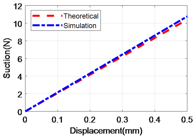
As shown in Fig. 7, the suction force corresponding to the displacement of the brake armature in the working air gap is obtained.
The ring is deformed in the axial direction. When the displacement is 0.5 mm, the required suction force is 10.77 N. The stiffness curve is obtained by fitting the data of the simulation results. The simulation stiffness of leaf spring Ksim is 20.83 N mm−1.
Substituting the design parameters in Table 1 into Eq. (6), the corresponding deflections of the leaf spring under the different forces can be obtained. The theoretical stiffness of leaf spring KTheo=21.52 N mm−1. The two stiffness curves are shown in Fig. 8, and the difference between the theoretical and simulated stiffness is 3.2 %.
4.2 Permanent magnet suction simulation
The magnetic permeability of magnetic materials varies non-linearly with the magnetic field strength. In order to make the simulation results closer to the real results, this electromagnetic simulation chooses to use the magnetisation curve (BH curve) of the corresponding material when the material permeability is defined. The magnetic saturation phenomenon existing in the structure can be reflected by the simulation results, and the magnetic flux density distribution in the working air gap can also be reflected more accurately. The simulation parameters are shown in Table 2.
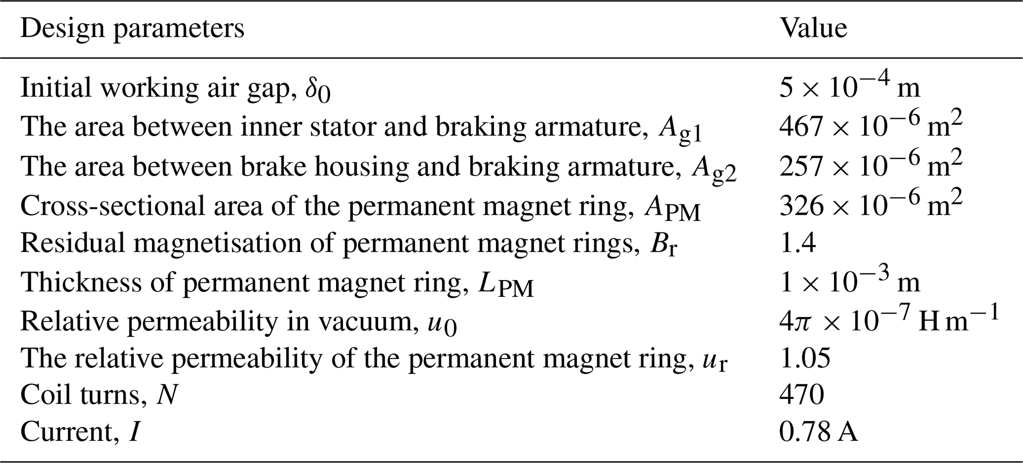
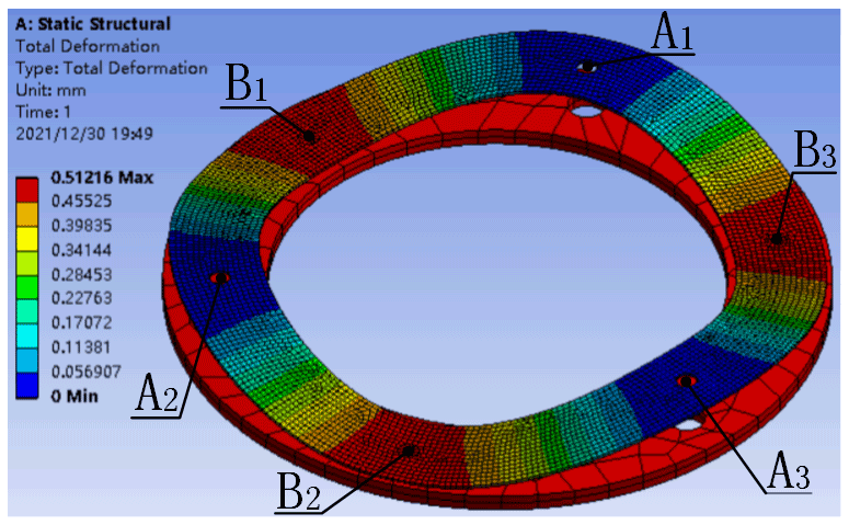
Figure 9 shows the cross-section view of magnetic flux density and the trend view of magnetic flux distributed in the brake when it is not energised. The working air gaps δ1 and δ2 are simulated from 0 to the maximum working air gap of 0.5 mm, and the corresponding average magnetic flux densities and are obtained. The relationship between the simulated working air gap and the magnetic induction can be obtained.
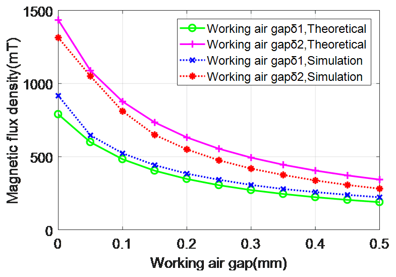
By substituting the design parameters in Table 2 into Eqs. (15) and (16) to obtain the average magnetic flux densities and in the working air gaps δ1 and δ2, where , the curve of the theoretical working air gap and its corresponding magnetic induction intensity is obtained.
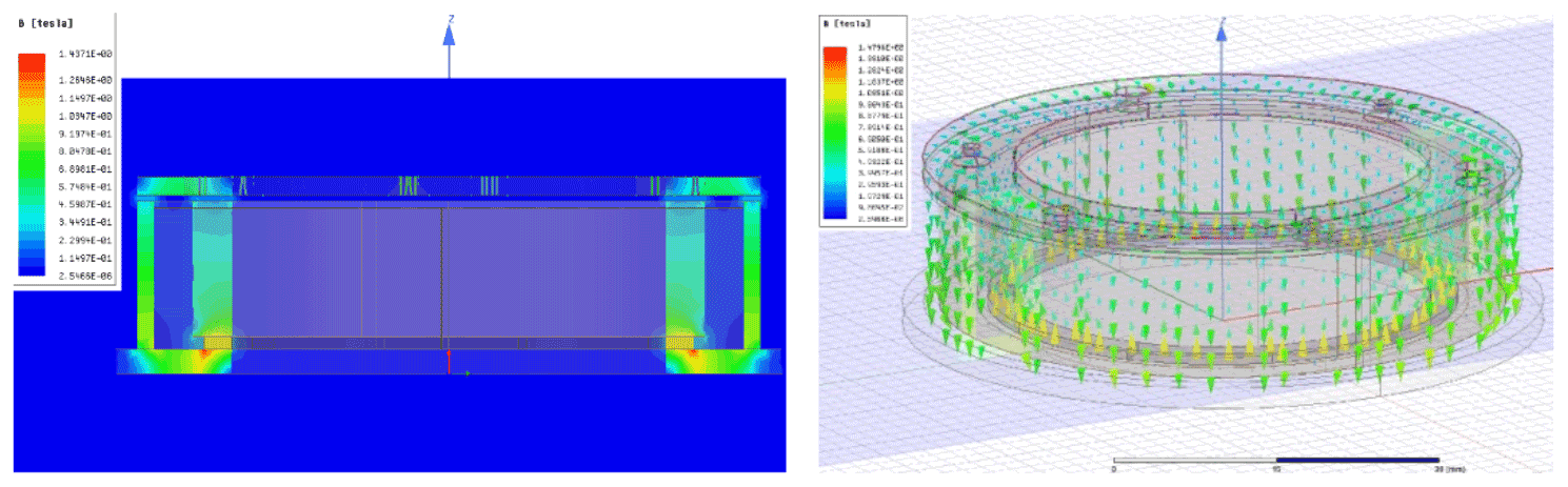
Figure 10 shows the corresponding curves of different working air gap distances and magnetic flux density obtained by simulation calculation and theoretical derivation. When the working air gap is δ=0.5 mm, the magnetic flux densities in air gaps δ1 and δ2 are received through theoretical derivation and simulation calculation as 189, 343 and 222, 281 mT, respectively. When the working air gap δ=0, the flux densities are 789, 1434 and 916, 1314 mT. From this we notice that the magnetic flux density decreases with the increase in the working air gap distance.
The suction of the permanent magnet ring corresponding to the brake armature between 0 and 0.5 mm working air gap can be calculated by the finite-element simulation software, and the relationship between the simulated suction and the working air gap can be obtained by data fitting. Substituting the design parameters in Table 2 into Eq. (35), the theoretical suction-working air gap relationship can be derived. As shown in Fig. 11, when the working air gap δ=0, the suction force N, which is obtained by simulation. This is greater than the suction force N obtained by theoretical deduction. When the maximum working air gap δ=0.5 mm, the suctions N and N. The difference between the two results is 4.9 %.
When the brake is powered on, the brake armature is kept at the maximum working air gap under the pulling force of the leaf spring. After the brake is powered off, the suction N, which is larger than the elastic force of 10.77 N at the maximum working air gap 0.5 mm simulated in Sect. 4.1. At the maximum working air gap, the braking suction overcomes the elastic force of the leaf spring to pull the brake armature back to the braking position.

Figure 11Relationship between working air gap and suction for theoretical derivation and simulation calculation.
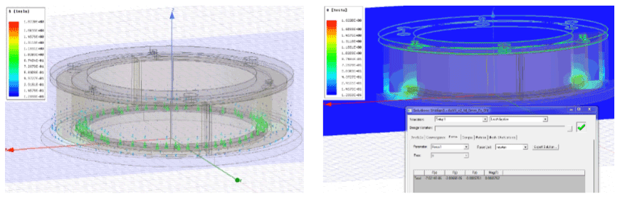
Figure 12a shows the distribution of the electromagnetic flux generated instantaneously in the structure when a current of 0.78 A is applied to the coil (470 turns × 0.78 A) and the brake armature is sucked on the brake body. As can be seen from Fig. 12b, the simulation results show that the permanent magnetic flux in the working air gaps is almost completely cancelled out, which means the suction is close to zero.
By substituting the design parameters in Table 2 into Eqs. (23), (26)–(28) and (34), the electromagnetic flux in the working air gaps after energisation can be calculated as Wb. The total flux in air gap is Wb after cancellation.
Both the total flux densities and the suction forces in the working air gaps δ1 and δ2 can be obtained as Bg1=0.016 T, Bg2=0.028 T, Fδ1=1.06 N, and Fδ2=1.93 N, respectively. The total suction is then 2.99 N
When energising the coil, the electromagnetic flux cancels out the permanent magnetic flux and the suction in the working air gaps is reduced to 0.01 N as a result of the simulation calculation and 2.99 N from the theoretical derivation. Both results are less than the restoring force (10.77 N) of the leaf spring simulated at the maximum tensile force (when δ=0) in Sect. 4.1, and the brake armature can be separated from the brake body under this tensile force.
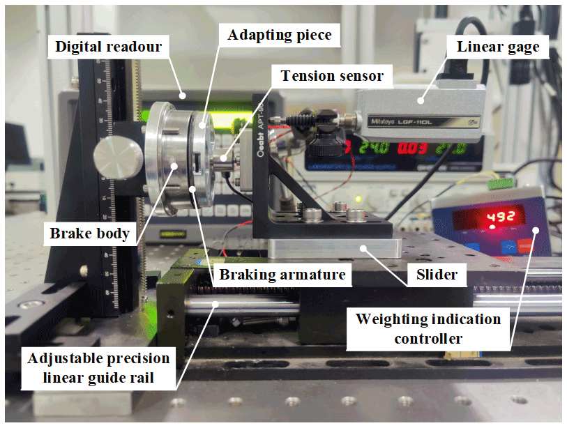
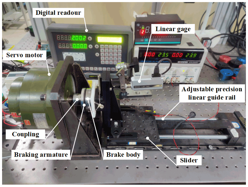
To verify the functionality of the proposed permanent magnet brake mechanism, a hardware platform is built. The experiment mainly tests the stiffness of the flexible ring in the working direction, the suction force of the brake armature under different working air gaps, and the maximum braking torque of the designed brake. A tension sensor (model: Viste VL13; measuring range: 20 kg; resolution: 0.8 %), a weighting indication controller (model: ST550LC-1), a linear gage (Model: Mitutoyo LGF-110-B, measuring range: 10 mm; resolution: 1 µm), a grating digital readout, rare earth permanent magnet DC servo motor (model: 130LCX-2), DC servo driver (model: AMC30A8), adapting piece, adjustable precision linear guide rail (resolution: 1 µm), an external power source, and a switch are used.
5.1 Stiffness test of leaf spring
In the stiffness evaluation, as shown in Fig. 13, the brake armature is connected to the adapting piece through the leaf spring, and the adapting piece is fixedly connected with the tension sensor and then installed on the precision slider of the adjustable guide rail. A linear gage is used to measure the moving distance of the slider on the adjustable guide rail.
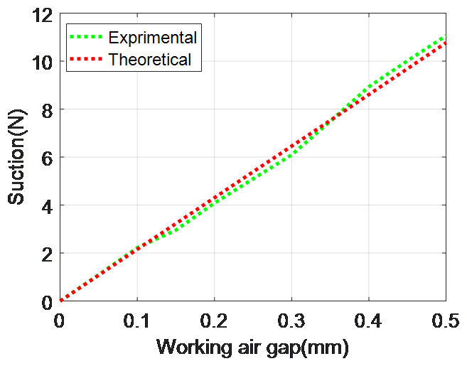
The experimental results show that when the working air gap is 0.5 mm, the suction force on the brake armature is 11.06 N. The comparison between the experimental and theoretical results of the stiffness of the leaf ring is shown in Fig. 14. The experimental stiffness of the leaf ring is KExp=22.22 N mm−1, which is 3.1 % different from the theoretical stiffness KTheo=21.52 N mm−1. The theoretical model is verified since the two stiffness curves have a good agreement.
5.2 Permanent magnet suction test
The braking armature is directly fixed with the adapting piece. A tension sensor is connected to the adapting piece and the precision slider to measure the suction force on the brake armature. A linear gage is used to measure the moving distance of the precision slider, as shown in Fig. 15.

By measuring the suction corresponding to different working air gaps, the relationship between the suction force of the brake and the working air gap can be obtained. In Sect. 4.2, the results of the theoretical model are compared through simulation calculations, and the results are generated through the comparison of three results.
As shown in Fig. 16, the curves of the experimental results curves are lower overall than curves of the theoretical and simulation results, but the overall trend of the three curves is almost the same. When the brake is in power-off state, the maximum suction of the experiment is 248.3 N, which is smaller than the theoretical result of 326.2 N and the simulation result of 410.1 N. However, when the working air gap is 0.5 mm, the maximum suction of the experiment is 15.7 N, which differs from the theoretical result of 18.7 N and the simulation result of 19.6 N by 3 and 3.9 N, respectively.
The theoretical and simulation means are more ideal in terms of boundary condition setting, which leads to large suction results when the brake is in the suction state. However, the overall trend of the three curves is relatively consistent. The established theoretical model has a certain reference for the actual design.
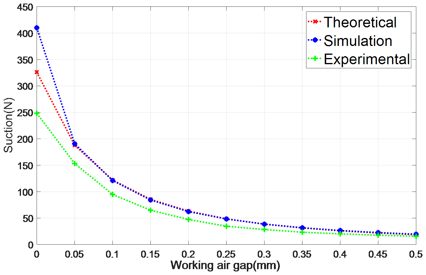
Figure 16Relationship between working air gap and suction for theoretical, simulation and experimental results.
5.3 Braking torque test
Constant current is supplied to the servomotor via the drive to output a given torque (motor torque factor KT=0.73 N m A−1, drive conversion factor KI=1.13 A V−1), as shown in Fig. 17. The brake armature is fixed to the motor output shaft via a coupling and the motor rotation drives the brake armature together. The brake body is connected to the slider. The brake body is mounted on the slider.
The maximum braking torque of the brake can be measured by adjusting the output torque of the servomotor and finally the maximum braking torque of the designed brake, MExp=1.39 N m.
The theoretical maximum braking torque can be calculated from Eqs. (34)–(37) in Sect. 3.2 and Table 1, which is MTheo=1.55 N m. The difference between the theoretical and experimental torque is 10.3 %. The main reason for this is that the theoretical suction is greater than the experimental suction in the power-off state, and the friction coefficient is an empirical value, which is different from the actual material.
The theoretical models are verified by means of finite-element software. The results are as follows.
-
The difference between the theoretical and simulation stiffness of the leaf ring is 3.2 %.
-
Two curves for the variation of magnetic flux density with distance in the working air gaps are generated by simulation. Comparing the theoretical curves, the trend is basically the same.
-
The relationship between the brake suction force and the working air gap is obtained by simulation. Comparing the theoretical results, the curve trend is basically the same, and at the maximum working air gap, the difference between the theoretical and simulation suction force results is 4.6 %.
-
After the system loses power, the brake suction can overcome the elastic force of the leaf ring and pull the braking armature back to the braking position at the maximum working air gap. After the power-on state, the electromagnetic flux cancels the permanent magnetic flux, and the suction in the working air gaps is reduced to 2.99 N for theory and 0.01 N for simulation. The difference between the two results is 2.98 N, indicating that the simulation and theoretical results correspond to each other.
It is experimentally verified that the actual stiffness of the leaf spring differed from the theoretically derived stiffness by 3.1 %. It is verified by experiments that the relationship between the theoretical suction and the working air gap is basically the same as the actual measured relationship. The maximum braking torque of the designed brake is 1.55 N m, which is 7.7 % different from the theoretically derived maximum braking torque.
No data sets were used in this article.
RT, XX and DF contributed to the conception of the study. RT mainly wrote this paper. JZ helped RT to perform the data analyses and wrote the manuscript. BY helped RT to perform the analysis with constructive discussions. BL helped RT to perform the experiment.
The contact author has declared that none of the authors has any competing interests.
Publisher’s note: Copernicus Publications remains neutral with regard to jurisdictional claims in published maps and institutional affiliations.
The authors would like to thank the support from the key laboratory of science and technology, National University of Defense Technology (NUDT).
This research has been supported by the National Key Research and Development Program of China (grant no. 2019YFB2004700).
This paper was edited by Guowu Wei and reviewed by two anonymous referees.
Cheng, Z., Jin, M. H., Liu, Y. C., Zhang, Z., L Yu, L., and Hong, L: Singularity Robust Path Planning for Real Time Base Attitude Adjustment of Free-floating Space Robot, International Journal of Automation and Computing, 14, 169–178, https://doi.org/10.1007/s11633-017-1055-1, 2017.
Gibbs, E. G. and Office, W.: Canada and the international space Station program: overview and status, Acta Astronaut., 51, 591–600, 2002.
Hirzinger, G., Albu-Schaffer, A., Hahnle, M., Schaefer, I., and Sporer, N.: On a new generation of torque controlled light-weight robots, IEEE Int. Conf. Robot., 4, 3356–3363, https://doi.org/10.1109/ROBOT.2001.933136, 2001.
Jin, Y., Kou, B., Li, L., Li, C., Pan, D., and Song, K.: Analytical Model for a Permanent Magnet Eddy-Current Brake With Transverse Edge Effect, IEEE Access, 7, 61170–61179, https://doi.org/10.1109/ACCESS.2019.2915973, 2019.
Kumar, B., Sivakumar, K., Rao, Y. S., and Karunanidhi, S.: Design of a New Electromagnetic Brake for Actuator Locking Mechanism in Aerospace Vehcile, IEEE T. Magn., 53, 1–6, https://doi.org/10.1109/TMAG.2017.2707242, 2017.
Li, G.: Research on Modular Compliant Joint of Light Weight Robotic Arm, Master Thesis, Harbin Institute of Technology Mechatronic Engineering (China), 2015.
Magnani, P., Rusconi, A., Gonzalez, J. F., Campo, P., Chomicz, R., Magnani, G., Avionica, S. G., Sener Ingeniería, and Marco, S.: Design and Development of an Integrated Joint for the Dextrous Robot Arm, International Conference on Robotics and Automation, http://www.xueshufan.com/publication/2182155975 (last access: 1 August 2022), 2006.
Matsueda, T., Kuraoka, K., Goma, K., Sumi, T., and Okamura, R.: JEMRMS system design and development status, Telesystems Conference, http://ieeexplore.ieee.org/document/148052 (last access: 1 August 2022), 2002.
Mugnuolo, R., Pippo, S. D., Magnani, P. G., and Re, E.: The SPIDER manipulation system (SMS) The Italian approach to space automation, Robot. Auton. Syst., 23, 79–88, https://doi.org/10.1016/s0921-8890(97)00061-4, 1998.
Mugnuolo, R., Bracciaferri, F., Didot, F., Colombina, G., and Pozzi, E.: EUROPA – External Use of Robotics for Payloads Automation, Artificial Intelligence, Robotics and Automation in Space, http://www.researchgate.net/publication/268460235_Europa_External_Use_of_RObotics_For_Payloads_Automation (last access: 1 August 2022), 1999.
Sallaberger, C.: Canadian space robotic activities, Acta Astronaut., 41, 239–246, https://doi.org/10.1016/s0094-5765(98)00082-4, 1997.
Shao, Z., Sun, H., Jia, Q., Ping, Y., and Tan, Y.: Development of a General 2-DOF Space Module, IEEE/RSJ Int. C. Int. Robot., 2006, 1002–1007, https://doi.org/10.1109/IROS.2006.281782, 2006.
Verhoeven, D.: SPACE STATION: Space mechanisms and tribology for the joints of the European Robot Arm (ERA), 8th European Space Mechanisms and Tribology Symposium, http://www.researchgate.net/publication/253554591_SPACE_STATION_Space_mechanisms_and_tribology_for_the_joints_of_the_European_Robot_Arm_ERA (last access: 1 August 2022), 1999.
Yasa, Y., Sincar, E., Ertugrul, B. T., and Mese, E.: Design considerations of electromagnetic brakes for servo applications, IEEE International Symposium on Industrial Electronics, 214, 768–774, https://doi.org/10.1109/ISIE.2014.6864709, 2014.
- Abstract
- Introduction
- Structural design and working principle
- Mechanical-electric-magnetic coupling dynamics modelling
- Finite-element analysis (FEA) comparison
- Experimental verifications
- Conclusion
- Data availability
- Author contributions
- Competing interests
- Disclaimer
- Acknowledgements
- Financial support
- Review statement
- References