the Creative Commons Attribution 4.0 License.
the Creative Commons Attribution 4.0 License.
 | 03 Aug 2022
Design of an origami-based cylindrical deployable mechanism
Long Huang
Peng Zeng
Lairong Yin
Juan Huang
In this paper, an innovative cylindrical deployable mechanism (DM) based on rigid origami is presented, which is used to design a parabolic cylindrical deployable antenna. The mechanism can be deployed from the cuboid folded configuration to the cylindrical unfolded configuration with only one actuator. First, an innovative deployable string is proposed based on different types of four-vertices origami unit cells and kirigami techniques. By considering the units as 6R single-loop mechanisms, the kinematics of the origami unit cells are analyzed. Through the connection of identical deployable strings, the cylindrical DM is constructed, and its mobility is analyzed utilizing the screw theory. Then the proposed DM is used to design a parabolic cylindrical deployable antenna. A number of pillars are installed on the panels of the DM, and their lengths are determined to fit the required parabolic cylindrical surface. To verify the feasibility of the design, a scaled prototype of the deployable antenna is constructed.
- Article
(7476 KB) - Full-text XML
- BibTeX
- EndNote


Deployable mechanism (DM) refers to a kind of mechanism that can be deployed from the folded configuration into the desired configuration in a specific manner. The ability of configuration change enables DMs to be widely applied to aerospace engineering, civil engineering, and medical equipment, such as space antennas and reflectors (You and Pellegrino, 1997; Song et al., 2017; Andrews et al., 2020; Ma et al., 2021), solar panels (Kuang et al., 2004; Kumar and Pellegrino, 2012), retractable rooftops (Kassabian et al., 1999; Delaney, 2014; Cai et al., 2019), and emergency shelters (Kiper et al., 2015; Cai et al., 2015). Large-scale DMs are usually constructed by assembling similar modules with specific connecting approaches. Typical modules include scissor mechanisms (Bai et al., 2013; Sun et al., 2014) and single-loop mechanisms such as Bennett mechanisms (Chen and You, 2008; Song et al., 2017), Mycard mechanisms (Liu and Chen, 2009), Bricard mechanisms (Lee, 1996), Sarrus-like mechanisms (Chen et al., 2013; Lu et al., 2016), and also include origami patterns such as the Miura-ori pattern (Gattas et al., 2013), the waterbomb pattern (Lee et al., 2021), the Resch pattern (Yang et al., 2022), and the cuboid-twist pattern (Hull, 2014). These modules are usually connected by sharing links or kinematic pairs (Soykasap et al., 2004; Huang et al., 2021a; Zhao et al., 2009; Tian et al., 2010).
In recent years, researchers have proposed and analyzed various DMs that can be deployed in one to three dimensions. You and Pellegrino (1996) proposed a one-dimensional deployable mast based on the pantograph; the stiffness of the mast in the deployed configuration can be strengthened through passive cables. Ding et al. (2013) reported a deployable prism with half-closed polyhedron characteristics based on the polyhedral linkages and introduced the combination method between prism cells. Based on the Hoekens straight-line linkage, Lu et al. (2014) proposed a series of one-dimensional deployable prisms, which can keep the dimension of the cross-section while being deployed. Zhao et al. (2018) designed a reconfigurable extended joint to optimize a deployable articulated mast and proposed a method of sequentially assembling reconfigurable extended joints to increase the mast's stiffness. Kim et al. (2021) proposed a deployable truss based on scissor-like elements, and this truss can be stored in a flat form, which greatly improves the packaging efficiency. For two-dimensional deployable reflectors, You and Pellegrino (1997) developed a support structure for a large deployable mesh reflector, which has a small shape error. Huang et al. (2012) introduced several efficient methods for the mobile connection between deployable single-loop mechanisms and also proposed a novel approach to eliminate the overconstraints in large DMs. Qi et al. (2016) proposed a one-degree-of-freedom (1-DOF) deployable ring with a high packaging efficiency by taking a set of planar six-bar linkages as the module. Lu et al. (2017) designed a deployable network with cylindrical surface based on Bennett linkages and introduced the connection method of units in detail. Song et al. (2019) constructed a 1-DOF cable-truss hybrid double-layer DM using equilateral Bennett linkages and planar symmetric four-bar linkages, which improves the stiffness of the mechanism without losing portability. Han et al. (2019) proposed five new types of ring truss DMs, which enriched the configurations of deployable antennas. Huang et al. (2021b) presented a novel type of 2-DOF single-loop mechanism based on the Sarrus mechanism, and obtained a series of cylindrical DMs with two DOFs.
In comparison with the one-dimensional and two-dimensional DMs, the three-dimensional DMs has significant size changes in three directions. Based on prismatic joints, Agrawal et al. (2002) proposed a class of deployable polyhedrons of given shape. Kiper (2009) proposed several new linkages based on the Fulleroid, which can be applied to the construction of deployable polyhedral mechanisms. Yang and Chen (2018) proposed a convertible DM by appropriately configuring the movable joint, which can realize the 1-DOF transformation between a tetrahedron and a truncated tetrahedron. In addition, Chen et al. (2018) proposed a 1-DOF shape transformation between two paired polyhedrons by introducing 6R spatial links. Xiu et al. (2020) presented a Sarruss-like overconstrained spatial eight-bar linkage and an associated Fulleroid-like DM.
DMs composed of origami patterns have seen a surge in interest from researchers in recent years. Lang (2004) improved the diffractive lens of space telescopes with an unique combined origami creases, which have the advantages of being lightweight and deployable. Karni and Pellegrino (2007) proposed a small-span deployable roof with low cost and light weight by combing the scissor linkage and a concertina-like origami pattern. Tachi (2010) reported a deployable corridor for connecting the openings of two separate buildings with different sizes and orientations using the generalized degree-4 vertices origami. Wilson et al. (2013) proposed two schemes for designing a sunshield concept based on the Kresling folding pattern and the Miura–Tachi folding pattern separately. Maanasa and Reddy (2014) proposed a deployable tent, which can be deployed in 1 min under a single-person operation. Zirbel et al. (2015) reported a deployable solar array based on the Hanaflex crease pattern, which greatly reduced the storage volume. Cai et al. (2015) proposed an origami-based deployable shelter and analyzed its geometry and motion. Liu et al. (2016) developed a family of deployable prismatic structures by assembling degree-4 vertices and proposed the general design method of deployable prismatic structures. Gattas et al. (2017) proposed a deployable arch bridge based on origami and explored its bearing capacity. Wang et al. (2018, 2021) proposed a Sym-kiri network based on the Yoshimura origami pattern, which was applied to the space cylindrical deployable structure. Based on the waterbomb pattern, Lee et al. (2021) proposed a transformable wheel with a high load capacity. Georgakopoulos et al. (2021) comprehensively introduced emerging research on origami-based deployable antennas and summarized the main advantages and important challenges of origami antennas.
The cylindrical DM is one of the most widely used structures. The reported designs are usually based on the linkage mechanisms, especially the Bennett mechanism, which can achieve a high packaging efficiency and meet the requirements of lightweight design. However, the hinge arrangement of such mechanisms usually concentrates on the end of the links, which is a challenge for the installation of the hinges and the assurance of the overall stiffness of the mechanism. Therefore, it is necessary to develop more cylindrical DMs based on origami since the hinges of origami structures are distributed at the edge of the panels. In this paper, an innovative type of 1-DOF cylindrical DM is proposed by combining different degree-4 vertices origami unit cells. The DM can realize the transformation from the cuboid folded configuration to the cylindrical surface configuration with only one actuator. In comparison with the reported Bennett networks, the dispersed hinge arrangement of the proposed DM makes it easier to achieve higher stiffness.
The rest of this paper is organized as follows. In Sect. 2, the research methodology is described. In Sect. 3, the innovative origami-based deployable string is proposed, and its kinematics are discussed in detail. In Sect. 4, the cylindrical DM is constructed by connecting identical deployable strings. In Sect. 5, the proposed DM is used to design a parabolic cylindrical deployable antenna, and the scaled prototype of the antenna is manufactured to verify the feasibility of the design.
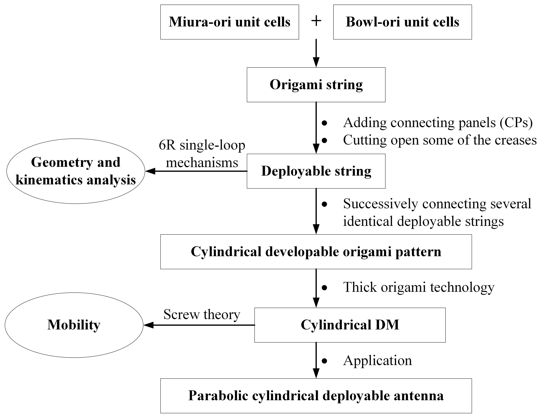
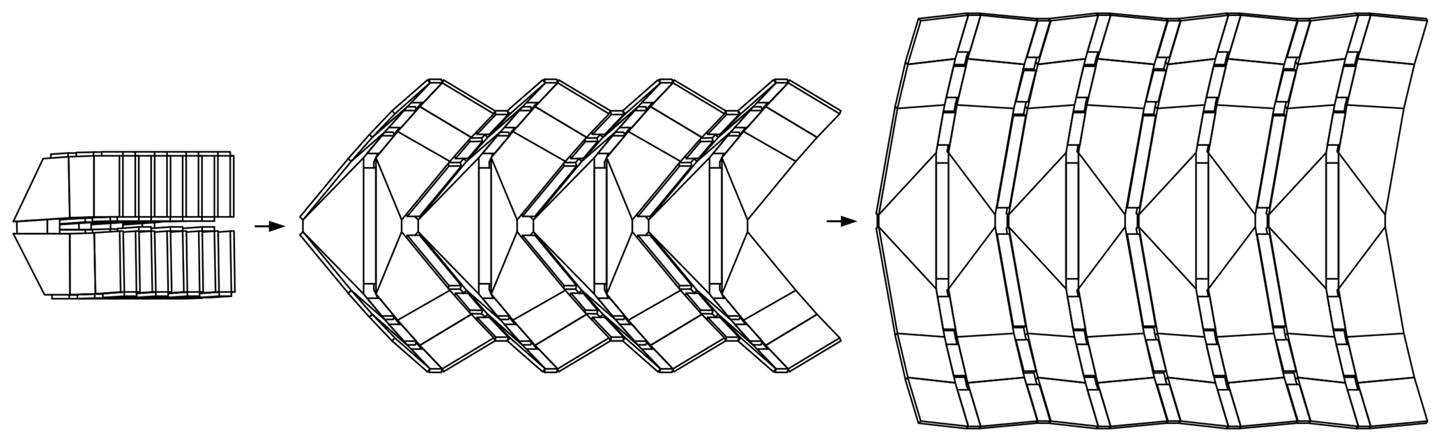
This paper mainly involves the design and analysis of a cylindrical DM. First, an origami string is constructed by combining two Miura-ori unit cells and four Bowl-ori unit cells. By adding connecting panels (CPs) and cutting open some of the creases, the origami string gradually evolves into a deployable string. Then, by considering the unit cells of the deployable string as 6R single-loop mechanisms, the geometry and kinematics of the deployable string are analyzed in detail. Further, a cylindrical developable origami pattern is constructed by successively connecting several identical deployable strings. Through thick origami technology, the final cylindrical DM is obtained, and its mobility is analyzed utilizing screw theory. Finally, the proposed DM is used to design a parabolic cylindrical deployable antenna.
To make the above description more intuitive, the schematic representation of the research workflow is given, as shown in Fig. 1.
3.1 Two types of 4-vertices
The origami pattern is a combination of many origami n-vertices – unit cells where n creases connected to n rigid panels meet at a point. Origami vertices can be classified into Euclidean origami and non-Euclidean origami (Waitukaitis et al., 2020). In essence, the sum of sector angles (the angle formed by adjacent creases, as shown in Fig. 2) in the Euclidean vertex is equal to 2π, while the sum of sector angles in the non-Euclidean vertex is not. In other words, the Euclidean origami pattern can be directly obtained by folding the paper, namely the pattern is flat-deployable, while the non-Euclidean origami pattern cannot be obtained by folding procedures unless it goes through specific tailoring and gluing.
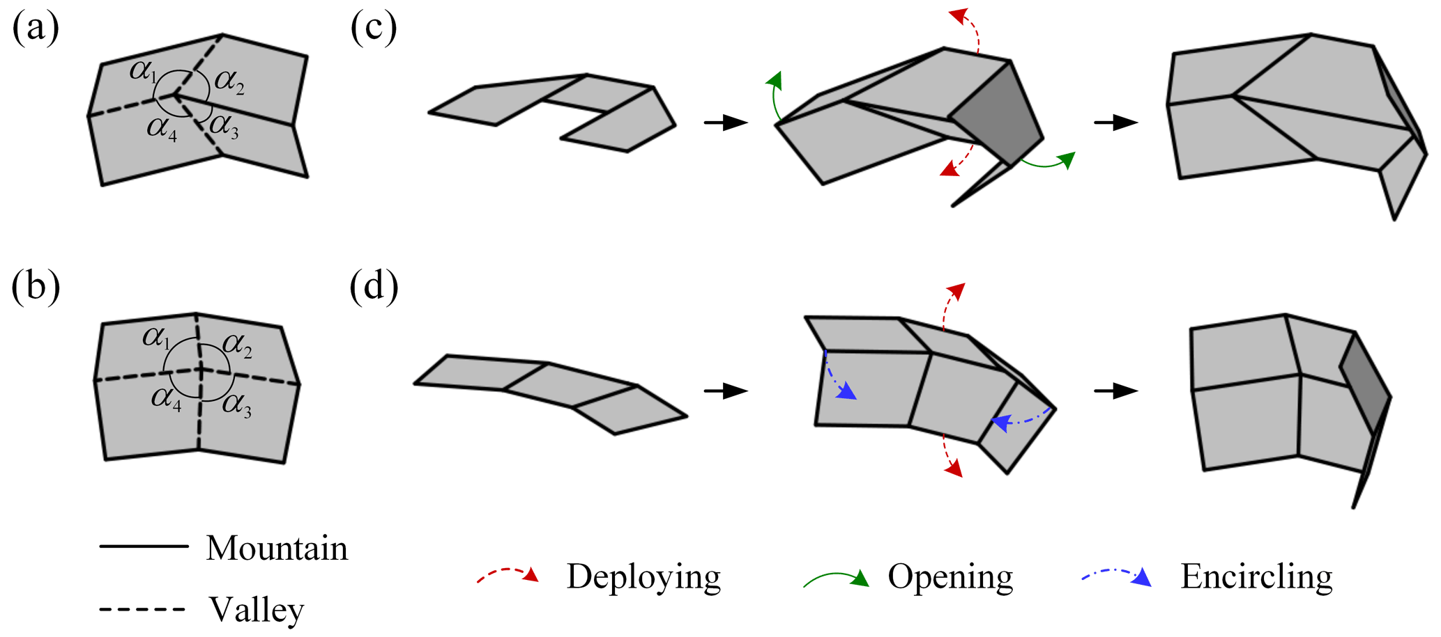
Figure 2Two types of 4-vertices origami unit cells and the corresponding combined origami patterns: (a) the Miura-ori unit cell, (b) the Bowl-ori unit cell, (c) the combination of two Miura-ori unit cells and their motion pattern, and (d) the combination of two Bowl-ori unit cells and their motion pattern.
Typical 4-vertices unit cells of Euclidean origami and non-Euclidean origami are shown in Fig. 2, where the unit cell in Fig. 2a is Miura-ori, and the unit cell in Fig. 2b can be named Bowl-ori due to its deployed shape. The combination of two Miura-ori unit cells can realize the deploying-opening motion (Fig. 2c). In comparison, the combination of two Bowl-ori unit cells can realize the deploying-encircling motion (Fig. 2d) (Huang et al., 2022).
3.2 Design of the deployable string
An origami string can be obtained by combining two Miura-ori unit cells and four Bowl-ori unit cells, which is a slender structure with two symmetrical planes, as shown in Fig. 3a. The combined motion of the deploying-opening and the deploying-encircling enables the origami string to realize the transformation from the flat configuration to the arc configuration. The origami string consists of four types of panels, namely the middle isosceles trapezoidal panels (MPs), the right angle trapezoidal panels (RPs), the isosceles trapezoidal panels (IPs), and the end rectangular panels (EPs). For the convenience of kinematic analysis, the geometrical parameters of the panels are defined in Fig. 3b. Specifically, the long base and the height of MPs are denoted by l1 and h1, and the base angle of MPs is denoted by α (). The short base of RPs is denoted by l2. The long base and the base angle of RPs are denoted by l3 and β () separately. The length of EPs is denoted by l4.
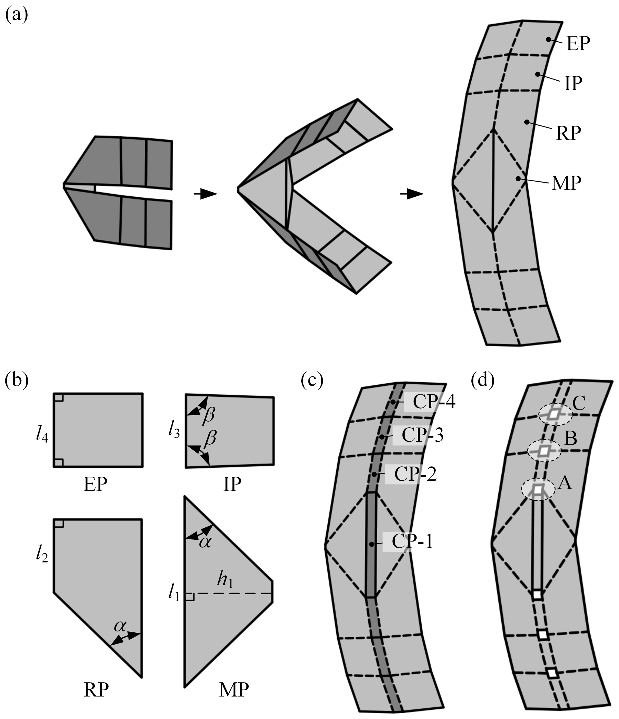
Figure 3Design of the deployable string: (a) an origami string consisting of two Miura-ori unit cells and four Bowl-origami unit cells and its deployment process; (b) four types of panels that make up origami string and their geometrical parameters, where α, ; (c) adding CPs (CP-i, i = 1–4) in the middle of the origami string; and (d) the deployable string after cutting open the creases.
Furthermore, the structure of the origami string is optimized to facilitate its engineering application. First, as shown in Fig. 3c, a row of CPs (CP-1 to CP-4) with width l is added in the middle of the origami string to improve its functionality, which is also convenient for the design of its thick-panel model (Hull and Tachi, 2017). Then, to reduce the overconstraints and the number of hinges in the physical model, all the creases between CPs in this pattern are cut open. Finally, the deployable string is obtained as shown in Fig. 3d. There are three units (A, B, and C) with different parameters in the deployable string, where unit A evolves from the Miura-ori unit cell, and units B and C both evolve from the Bowl-ori unit cell. Thus, they are marked as UM-A, UB-B and UB-C separately.
3.3 Kinematic analysis of the deployable string
From the mechanism point of view, UM-A, UB-B and UB-C can be considered as the 6R single-loop mechanism by taking the panels as links and the creases as revolute joints. The D–H coordinate frames Fi are established on the equivalent mechanisms, as shown in Fig. 4, where the Zi-axis is along the creases; the Xi-axis is along the common perpendicular between Zi and Zi+1 (it is perpendicular to the plane expanded by Zi and Zi+1 if Zi and Zi+1 intersect). It is noteworthy that the subscript i+1 is replaced with 1 when i equals 6. The twist angle αi denotes the angle from Zi to Zi+1, positively about Xi; the joint variable θi denotes the rotation angle from Xi−1 to Xi, positively about Zi. In addition, the link length ai(i+1) denotes the distance of the common perpendicular between Zi and Zi+1 along Xi, and the offset di denotes the distance from Xi−1 to Xi along Zi. Therefore, according to the geometrical parameters of UM-A, we have
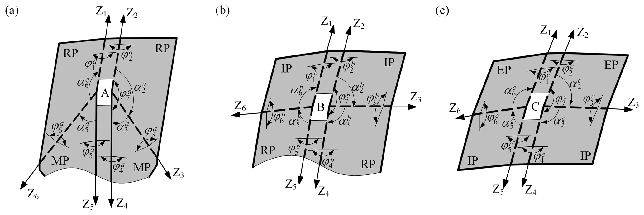
Figure 4Three units with different parameters in the deployable string and their DH parameters: (a) UM-A, (b) UB-B, and (c) UB-C. (, k = a, b, and c) denotes the dihedral angle between two panels connected by joint i in unit k. Specially, is the dihedral angle between two CPs in unit k.
Similarly, the DH parameters of UB-B and UB-C are as follows:
UM-A, UB-B, and UB-C satisfy the following kinematic equation:
where Qi(i+1) denotes the transformation matrix from Fi to Fi+1, and I3 is the 3×3 identity matrix. Substituting Eq. (1) into Eq. (4), the solution of the kinematic relationship is expressed as
where the joint variable θi belongs to since the panels cannot penetrate through each other in the deployable string; thus, we have for the valley crease and for the mountain crease. Equation (5) indicates that there is only one independent joint variable in UM-A, thus it is a 1-DOF mechanism, which is verified in Appendix A. Combining Eq. (5) and screw theory, we can obtain
where represents the joint variable of rotation between CP-1 and CP-2. In addition, according to Feng et al. (2018), the relationship between the joint variable θi and the dihedral angle between two panels connected by joint i (marked as φi) is described as
Thus, combining Eqs. (5)–(7), the relationship between dihedral angles in UM-A can be obtained as
Similarly, combining Eqs. (2)–(4) and Eq. (7), we have
During the deployment of the string, two MPs in UM-A undergo deploying motion, while two CPs (CP-1 and CP-2) undergo opening motion. This deploying-opening motion can be characterized in terms of two variables, i.e., and , where represents the angle between two MPs, . According to Eq. (8), their relationship can be obtained as shown in Fig. 5a. It can be concluded from the figure that the opening velocity increases gradually if the deploying velocity is uniform, and the base angle of MPs α affects the velocity range of the opening motion; as α increases, the velocity range increases. Similarly, the deploying-encircling motion of UB-B and UB-C can also be characterized. According to Eqs. (9) and (10), the relationship between and is shown in Fig. 5b, while the relationship between and is shown in Fig. 5c. If the deploying velocity is uniform, the encircling velocity increases gradually. As the base angle of IPs β increases, the velocity range of the encircling motion increases.
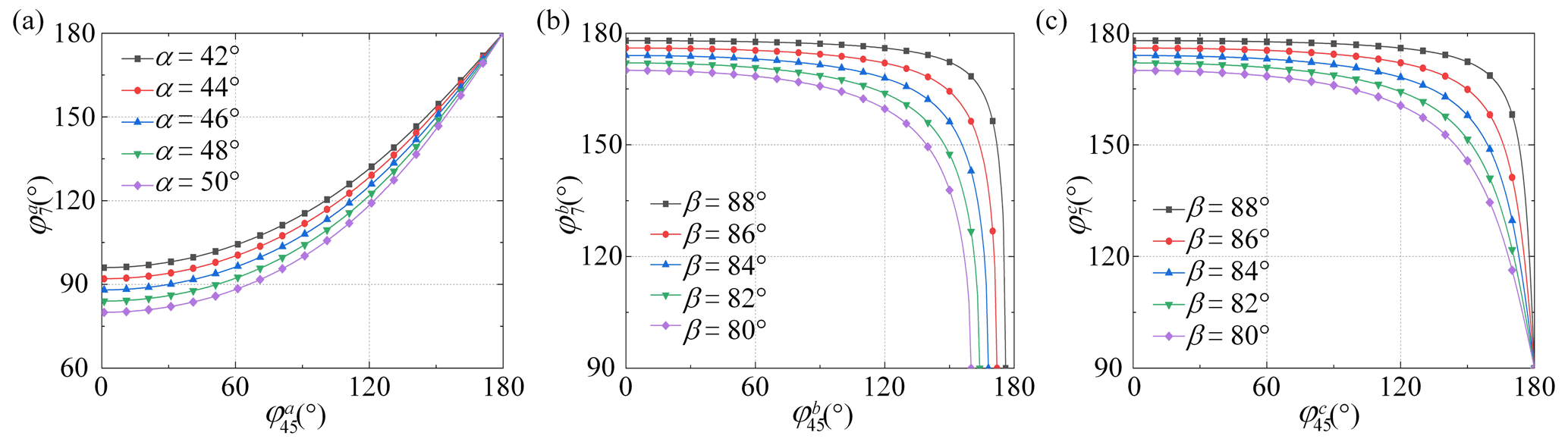
Figure 5Kinematic analysis of the deployable string: (a) the relationship between and in UM-A; (b) the relationship between and in UB-B; and (c) the relationship between and in UB-C, where and represent the angle between two RPs and two IPs separately. , .
4.1 Cylindrical deployable origami pattern
In this section, several identical deployable strings are successively connected through CPs (CP-5 to CP-7) to form the cylindrical developable origami pattern shown in Fig. 6a. This combined developable origami pattern retains the motion pattern of the deployable string, namely it can also realize the transformation from the folded configuration to the cylindrical configuration.
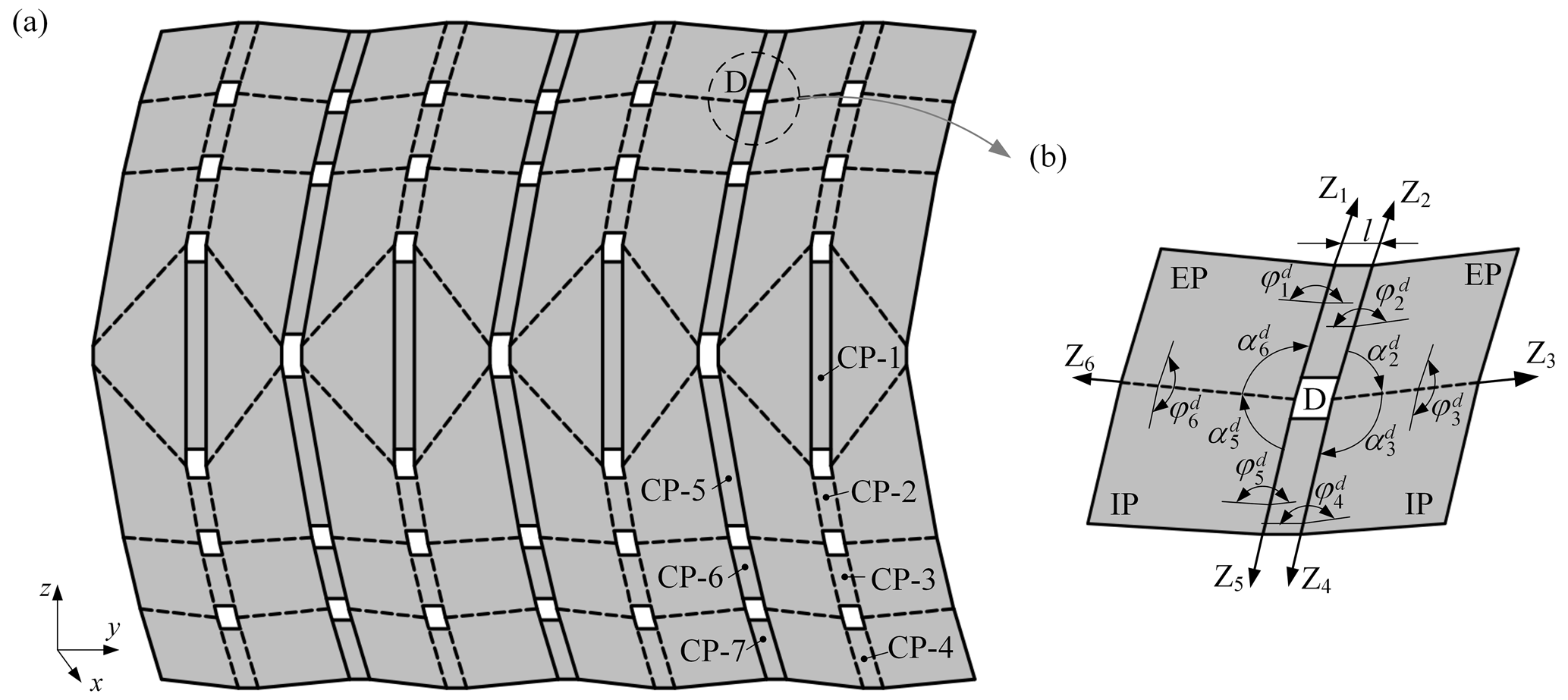
Figure 6Cylindrical deployable origami pattern: (a) the origami pattern composed of four identical deployable strings, (b) US-D.
In comparison with the deployable string, the combined developable origami pattern includes a new class of units, as shown in Fig. 6b, which is formed in the connection of two deployable strings. It can be regarded as the derivative of the Saddle-ori unit cell – a four-vertices unit cell of non-Euclidean origami, which unfolds in a saddle shape (Waitukaitis et al., 2020), and it is named by US. By considering it as a 6R single-loop mechanism, we obtain its DH parameters as
Combining Eqs. (4), (7) and (11), we have
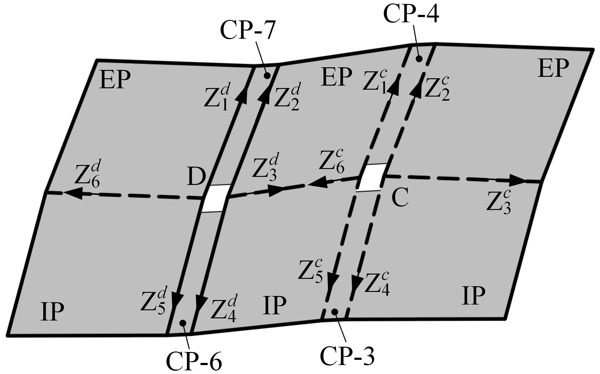
UB-C and the US-D are connected through common panels and form a combined mechanism shown in Fig. 7. Obviously, equals . Substituting this equation into Eqs. (10) and (12) yields
which indicates that and , namely CP-4 is parallel to CP-7, and CP-3 is parallel to CP-6. Similarly, it can be proved that CP-2 is parallel to CP-5 in the cylindrical deployable origami pattern shown in Fig. 6a. In other words, all CPs in the pattern are always perpendicular to the xoz plane during the deployment.
4.2 Thick-panel model of the deployable origami pattern
It is noteworthy that the above discussion deals with the zero-thickness origami pattern, and the DM requires nonzero-thickness panels. There are three types of units in the deployable origami pattern (UM, UB, and US), which are thickened with different methods. For UB, since the motion directions of all panels are on the same side of the pattern, the material is added to the other side to thicken the panels to the required thickness, as shown in Fig. 8d. For UM, after the same thickening operation, the volume of the panels near the hinge is trimmed to avoid interference (Denavit and Hartenberg, 1955), as shown in Fig. 8e. Unlike UB, the rotational axes in US need to be rearranged after the thickening operation, as shown in Fig. 8f.
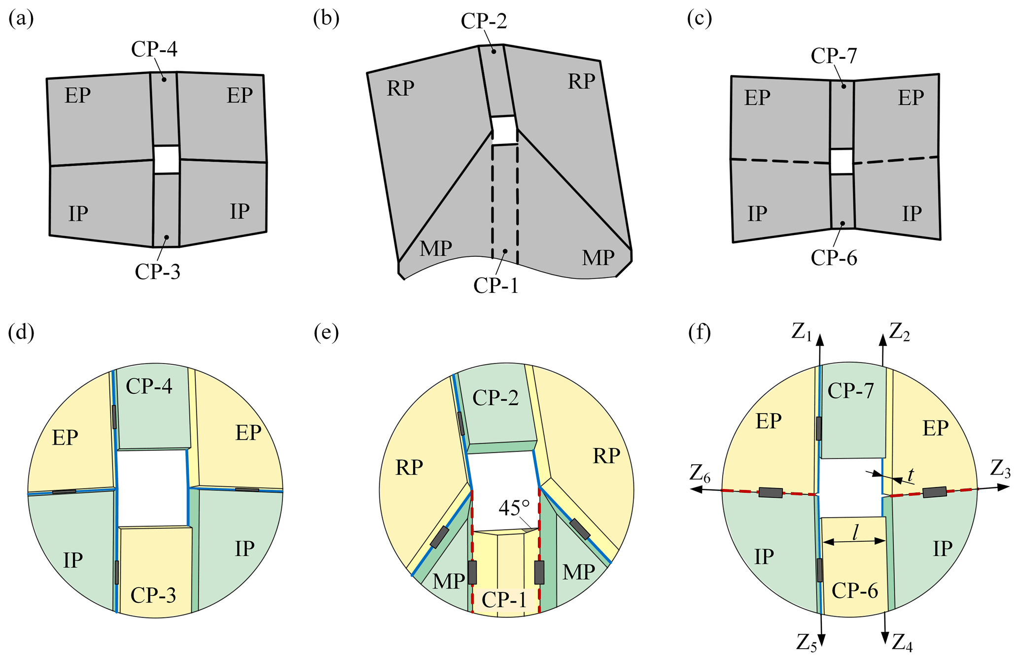
Figure 8Three types of units in the deployable origami pattern and the corresponding thick-panel model.
The thick-panel models of UM and UB have the same kinematics as their zero-thickness origami pattern since the thickening operation does not change the position of the rotational axes. For US, the influence of the thickening operation on the kinematic model is discussed as follows. The DH parameters of the thick-panel model of US-D are
Combining Eqs. (4), (7), and (14), we have
It is clear that Eq. (12) for the zero thickness of US-D and Eq. (15) for its thick-panel model are identical; thus, these two linkages are kinematically equivalent. Combining the above thickening operations, the cylindrical DM is obtained as shown in Fig. 9, which is proven to be 1-DOF according to the mobility analysis in Appendix A.
In this section, an example of the parabolic cylindrical deployable antenna is introduced, which mainly consists of three parts: the cylindrical DM, the pillars, and the cable layer, where the pillars can be used as nodes and be connected with the cable layer, and the cable layer is used to fit the required surface. The cylindrical DM is hollowed out to meet the lightweight requirement of the deployable antenna, as shown in Fig. 10a. Each pillar is vertically installed on the CP, as shown in Fig. 10b. Since all CPs in the cylindrical DM are perpendicular to the xoz plane, the axes of all pillars are always parallel to xoz plane during the deployment. The height of pillars (marked as Hp) depends on the target parabolic cylindrical surface, and the number of pillars depends on the accuracy requirement of the antenna reflector.
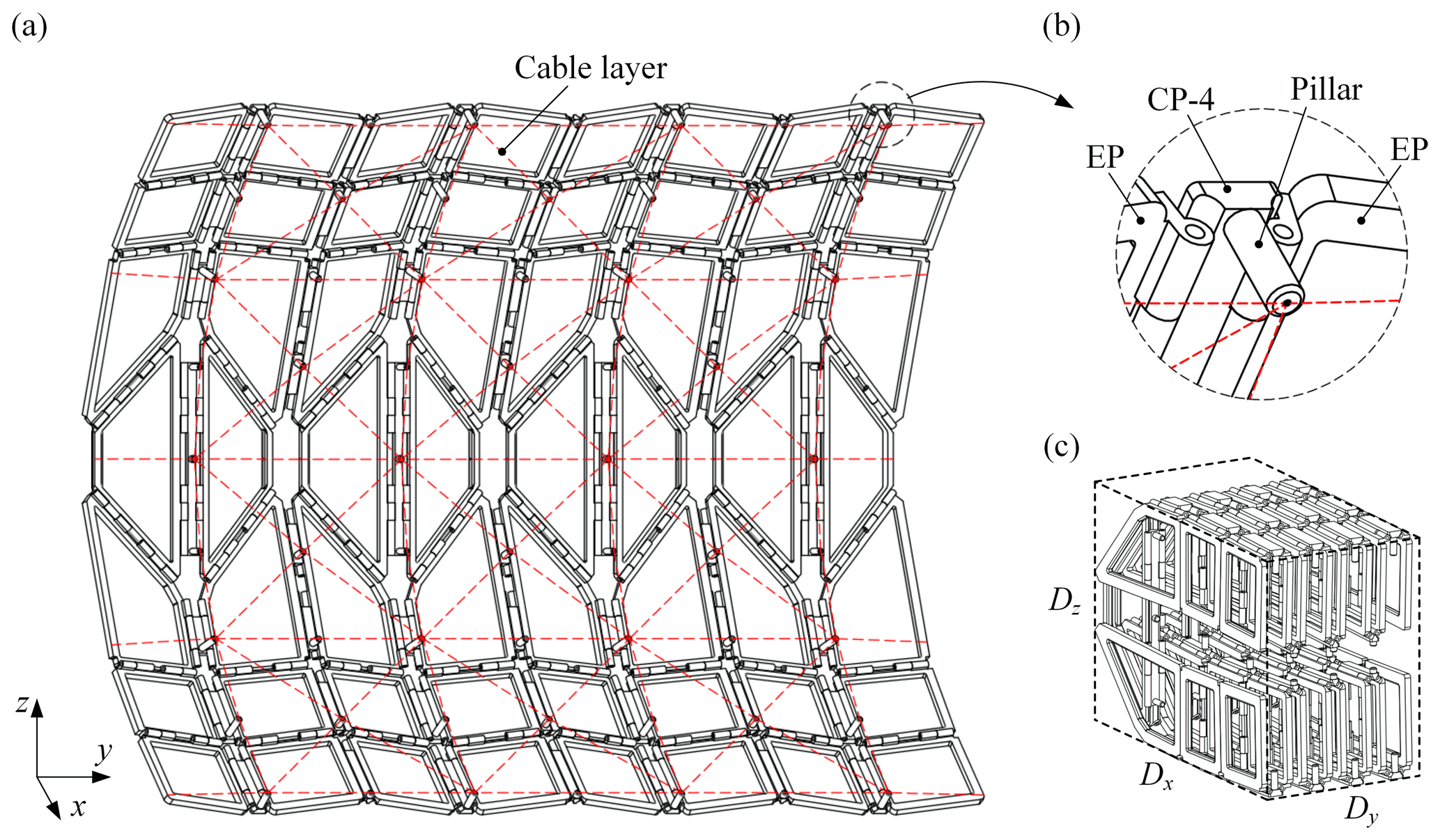
Figure 10The parabolic cylindrical deployable antenna: (a) the deployable antenna, (b) the pillar installed on CP, (c) the fully folded configuration of the antenna.
The reflection area and the fully folded volume of the antenna are determined by the parameters of the panels and the number of the deployable string (marked as N). The parameters of panels include l1, l2, l3, l4, l, h1, t, α, and β, where t represents the thickness of panels. The reflection area of the antenna depends on the size of panels and N; the reflection area increases when the size of each panel or N increases. As shown in Fig. 10c, the antenna can be fully folded into a cuboid with . The dimension of the cuboid in the x-axis (Dx) is mainly determined by h1, l2, l3, and l4, i.e., . The dimension of the cuboid in the y-axis (Dy) is determined by t, l, and N, i.e., . Besides, the dimension in the z-axis (Dz) is approximately equal to l1.
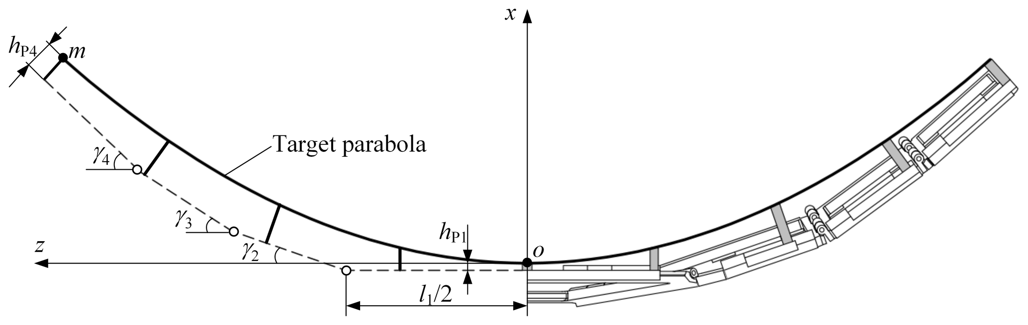
Furthermore, the relationship between the panel parameters, Hp and the target parabolic cylindrical surface is discussed. The cross-section of the deployable antenna is shown in Fig. 11, where hPi (i=1 and 4) denotes the height of the pillar installed on CP-i (marked as Pi). The coordinate system xoz is set up at the end of P1, and the angle between CP-i (i = 2–4) and the z-axis is denoted by γi. According to Eqs. (8)–(10), we obtain , , and . Therefore, the coordinates of the point m (the end of P4) can be expressed as
Then we obtain the equation of the target parabola as
Based on the above discussion, the following parameters are determined for the scaled antenna prototype to verify the feasibility of the design: N=4, l1=150 mm, l2=50 mm, l3=50 mm, l4=50 mm, l=10 mm, h1=60 mm, t=4 mm, α=44∘, β=88.52∘, hP1=5 mm, and hP4=13 mm. The panels are 3D printed with photosensitive resin material and hinged through metal pins; the pillars are integrated with CPs; the cables are fixed at the end of the pillars by screws, as shown in Fig. 12. The parabolic equation of the scaled antenna prototype is z2=533.47x, and its focal length is 133.37 mm. The scaled antenna prototype has a reflection area of 2.1×105 mm2 and a folded volume of 3.2×106 mm3.
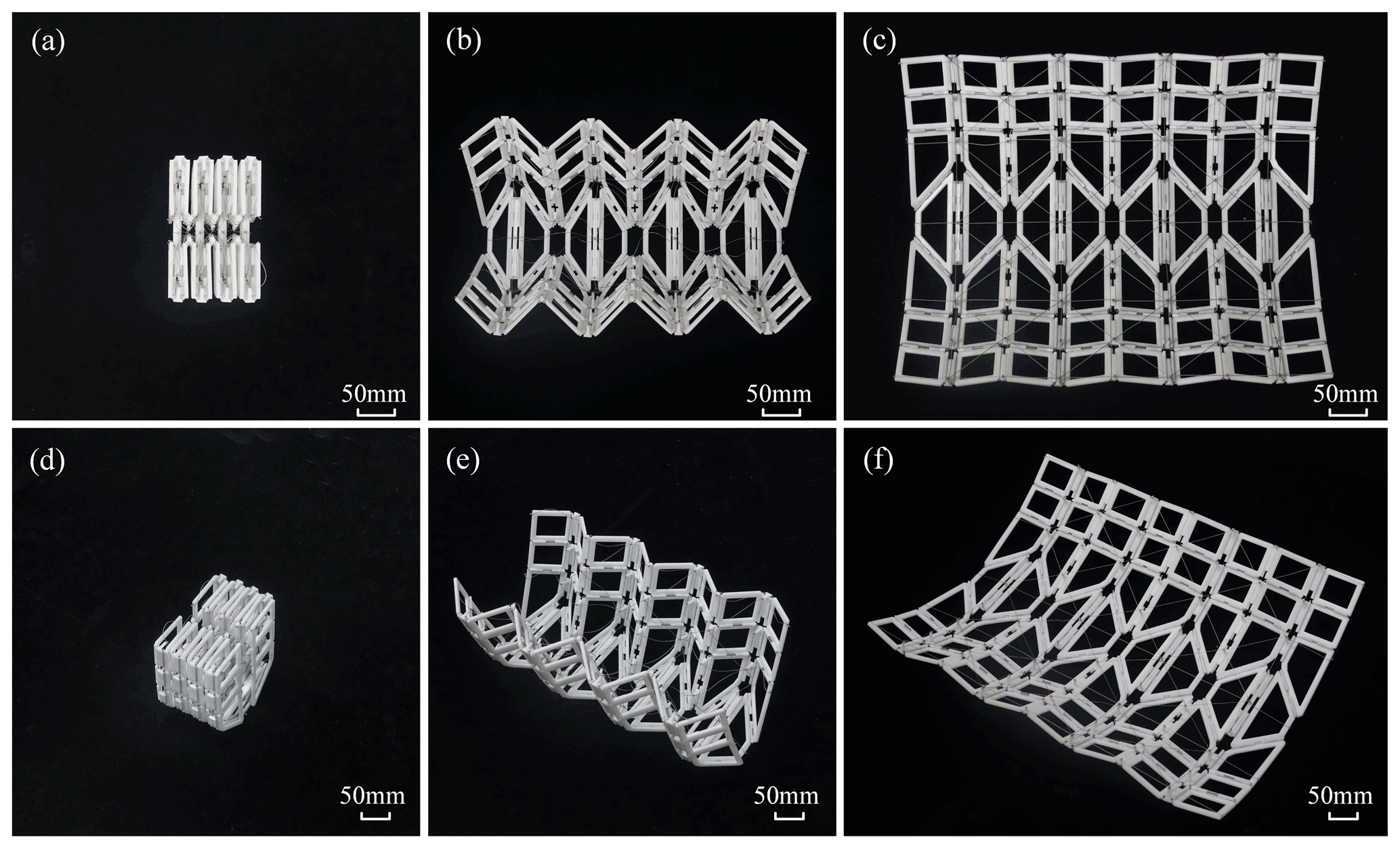
The complete deploying process of the scaled prototype is displayed in Fig. 12a–f, where panels (d)–(f) show views from a different direction at the same deployment position. As shown in Fig. 12d and f, the surface formed by cables at the working position is close to the target parabolic cylinder. During the experiment, the scaled prototype of the proposed antenna was deployed successfully, and there was no motion deviation in the whole deploying process, indicating that the DOF of the design remained at 1 in the whole motion cycle. Besides, the prototype demonstrates smooth foldability and deployability during the development, which proves the feasibility of the design.
In this paper, an innovative cylindrical DM that can be deployed from the cuboid-folded configuration to the cylindrical configuration is presented. The basic module of the cylindrical DM is a deployable string, which evolves from the origami string by adding CPs and cutting open some of the creases. In comparison with the DMs based on Bennett linkages, the dispersed hinge arrangement of the origami units makes the proposed DM easier to achieve higher stiffness. By considering the units as the 6R single-loop mechanism, we analyzed the kinematics and mobility of the deployable string along with the DM. The research shows that the proposed design has a stable deployment process with one DOF. Furthermore, the cylindrical DM is applied to the design of a parabolic cylindrical deployable antenna, and a scaled prototype of the antenna is constructed. The prototype demonstrates the smooth foldability and deployability in its motion, which proves the feasibility of the design.
In future work, more comprehensive theoretical research and experimental evaluation of the parabolic cylindrical antenna will be the focus, including the structural optimization and the research on the robustness performance. In addition, the application potential of the proposed DM in other engineering fields also deserves to be studied, such as the design of deployable roofs and temporary shelters.
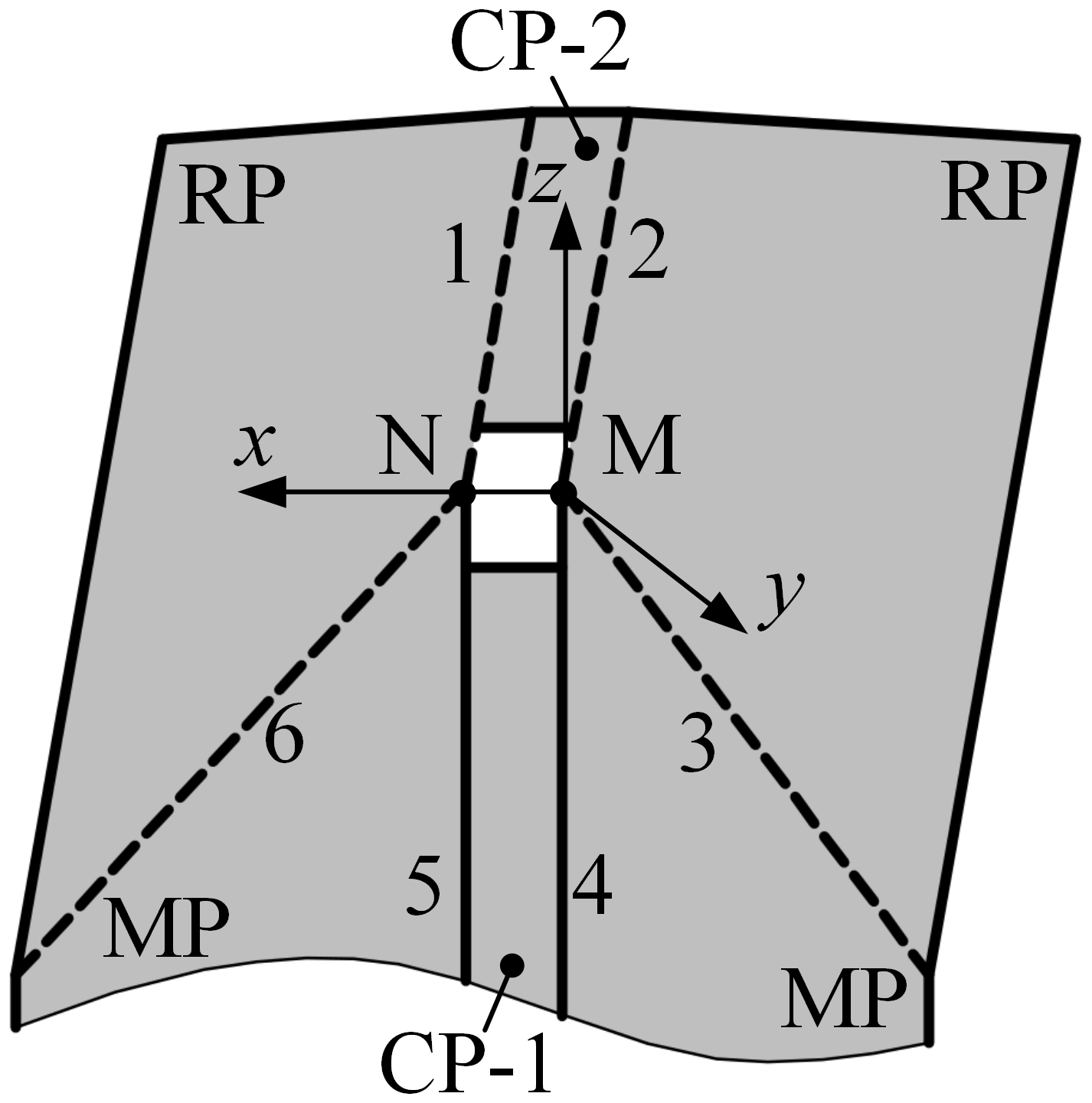
Screw theory is used to analyze the mobility of the deployable string (Huang and Xia, 2006; Huang et al., 2021c; Wei et al., 2010). As shown in Fig. A1, creases 2–4 of UM-A intersect at point M, and creases 5, 6, and 1 intersect at point N. The coordinate system M-xyz is set up at point M, where the x-axis is along , the y-axis is along crease 4, and the z-axis is obtained by the right-hand rule. Therefore, the screw motion equation of UM-A is as follows:
where ωi represents the revolute velocity of crease i (i=1, 2, …, 6), and $i represents the motion screw of the ith crease.
Equation (A1) can be described in matrix form as
Substituting Eq. (A2) into Eq. (A3), the rank of the matrix $ can be obtained, which is equal to five, namely there is one reciprocal screw in UM-A
Therefore, UM-A has one overconstraint. The mobility of UM-A can be obtained using the following formula (Zeng et al., 2015):
where M represents the mobility, n represents the number of components including the frame, g represents the number of kinematic pairs, and fi represents the DOF of crease i. Similarly, UB-B and UB-C can also be proved to be 1-DOF.
Furthermore, the mobility of the deployable string is analyzed. The topological constraint graph of the deployable string is shown in Fig. A2, where the circles represent panels, the arrows represent creases, Ui (i=1, 2, …, 6) represents the unit i, $ij (i=1, 2, …, 6; j=1, 2, …, 6) represents the motion screws of crease j in unit i.
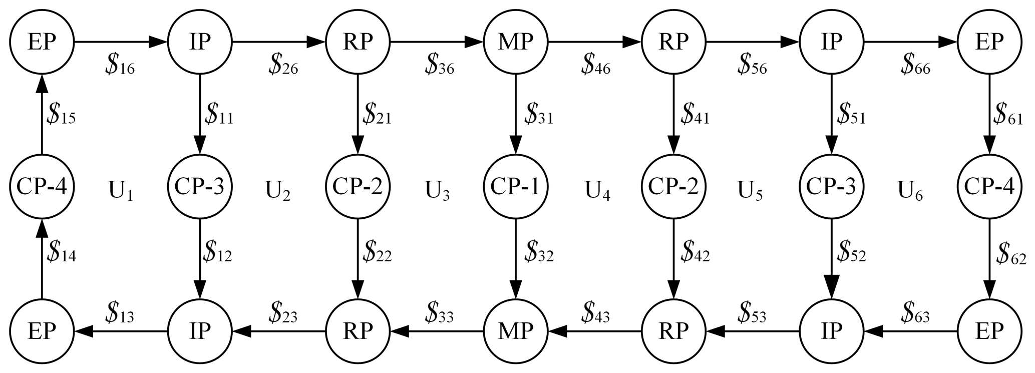
Based on Eq. (A1), the following screw equations can be obtained as
where ωij (i=1, 2, …, 6; j=1, 2, …, 6) represents the revolute velocity of crease j in unit i. The above equations can be presented in matrix forms as
The mobility of the deployable string can be obtained using the following formula (Wei et al., 2010):
where nc is the number of creases, namely the number of rows in the matrix $′, which is equal to 26, and the rank of the matrix $′ is equal to 25. Therefore, it can be concluded that the mobility of the deployable string is one during the folding process.
The mobility of the cylindrical DM can be obtained by analyzing the structure shown in Fig. A3, where = A, B; i=1, 2, …, 6) represents the closed-loop Ki, and $ (K = A, B; i=1, 2, …, 6; j=1, 2, …, 6) represents the motion screws of crease j in closed-loop Ki.

Figure A3Topological constraint graph of the structure consisting of one deployable string, two rows of CPs, and the panels connected to the CPs in the next deployable string.
Based on Eq. (A1), the following equations can be obtained:
where (K = A, B; i=1, 2, …, 6; j=1, 2, …, 6) represents the revolute velocity of crease j in the closed-loop Ki. The above equations are presented in matrix form as
The rank of the matrix $′′ is 43, and, thus, the cylindrical DM is 1-DOF according to Eq. (A8).
All the data used in the manuscript can be obtained on request from the corresponding author.
LH proposed the idea and methodology, PZ derived the equations, and LY and JH wrote this paper.
The contact author has declared that none of the authors has any competing interests.
Publisher's note: Copernicus Publications remains neutral with regard to jurisdictional claims in published maps and institutional affiliations.
This work has been financially supported by the National Natural Science Foundation of China (Project nos. 51805047 and 52175003), the Natural Science Foundation of Hunan Province (Project no. 2021JJ40259), the Hunan Young Talents Program (no. 2020RC3035), and the Outstanding Youth Program of Hunan Education Department (Project nos. 20B307 and 20B017).
This research has been supported by the National Natural Science Foundation of China (Project nos. 51805047 and 52175003), the Natural Science Foundation of Hunan Province (Project no. 2021JJ40259), the Hunan Young Talents Program (no. 2020RC3035), and the Outstanding Youth Program of Hunan Education Department (Project nos. 20B307 and 20B017).
This paper was edited by Daniel Condurache and reviewed by two anonymous referees.
Agrawal, S. K., Kumar, S., and Yim, M.: Polyhedral single degree-of-freedom expanding structures: design and prototypes, J. Mech. Design, 124, 473–478, https://doi.org/10.1115/1.1480413, 2002.
Andrews, D. W., Magleby, S. P., and Howell, L. L.: Thickness-utilizing deployable hard stops for origami-based design applications, Mech. Sci., 11, 395–410, https://doi.org/10.5194/ms-11-395-2020, 2020.
Bai, G., Liao, Q., Li, D., and Wei, S.: Synthesis of scaling mechanisms for geometric figures with angulated-straight elements, P. I. Mech. Eng. C-J. Mec., 227, 2795–2809, https://doi.org/10.1177/0954406213478280, 2013.
Cai, J., Deng, X., Xu, Y., and Feng, J.: Geometry and motion analysis of origami-based deployable shelter structures, J. Struct. Eng., 141, 06015001, https://doi.org/10.1061/(ASCE)ST.1943-541X.0001238, 2015.
Cai, J., Zhang, Q., Feng, J., and Xu, Y.: Modeling and kinematic path selection of retractable kirigami roof structures, Comput.-Aided Civ. Inf., 34, 352–363, https://doi.org/10.1111/mice.12418, 2019.
Chen, G. M., Zhang, S. Y., and Li, G.: Multistable Behaviors of Compliant Sarrus Mechanisms, J. Mechanisms Robotics, 5, 021005, https://doi.org/10.1115/1.4023557, 2013.
Chen, Y. and You, Z.: On mobile assemblies of Bennett linkages, P. R. Soc. A, 464, 1275–1293, https://doi.org/10.1098/rspa.2007.0188, 2008.
Chen, Y., Yang, F., and You, Z.: Transformation of polyhedrons, Int. J. Solids Struct., 138, 193–204, https://doi.org/10.1016/j.ijsolstr.2018.01.012, 2018.
Delaney, F.: Deployment mechanism for a retractable roof system for a large building structure, U.S. Patent, 8,635,813, 2014.
Denavit, J. and Hartenberg, R. S.: A kinematic notation for lower-pair mechanisms based on matrices, J. Appl. Mech., 22, 215–221, https://doi.org/10.1115/1.4011045, 1955.
Ding, X., Yang, Y., and Dai, J. S.: Design and kinematic analysis of a novel prism deployable mechanism, Mech. Mach. Theory, 63, 35–49, https://doi.org/10.1016/j.mechmachtheory.2013.01.001, 2013.
Feng, H. J., Peng, R., Ma, J. Y., and Chen, Y.: Rigid Foldability of Generalized Triangle Twist Origami Pattern and Its Derived 6R Linkages, J. Mechanisms Robotics, 10, 051003, https://doi.org/10.1115/1.4040439, 2018.
Gattas, J. M., Lv, W., and Chen, Y.: Rigid-foldable tubular arches, Eng. Struct., 145, 246–253, https://doi.org/10.1016/j.engstruct.2017.04.037, 2017.
Gattas, J. M., Wu, W., and You, Z.: Miura-base rigid origami: parameterizations of first-level derivative and piecewise geometries, J. Mech. Design, 135, 111011, https://doi.org/10.1115/1.4025380, 2013.
Georgakopoulos, S., Zekios, C., Sattar-Kaddour, A., Hamza, M., Biswas, A., Clark, B., Ynchausti, C., Howell, L., Magleby, S., and Lang, R.: Origami Antennas, IEEE Open Journal of Antennas and Propagation, 2, 1020–1043, https://doi.org/10.1109/OJAP.2021.3121102, 2021.
Han, B., Xu, Y., Yao, J., Zheng, D., Guo, X., and Zhao, Y.: Configuration synthesis of hoop truss deployable mechanisms for space antenna based on screw theory, AIP Adv., 9, 085201, https://doi.org/10.1063/1.5115219, 2019.
Huang, H., Deng, Z., and Li, B.: Mobile assemblies of large deployable mechanisms, Journal of Space Engineering, 5, 1–14, https://doi.org/10.1299/spacee.5.1, 2012.
Huang, L., Liu, B., Yin, L. R., Zeng, P., and Yang, Y. H.: Design and validation of a novel cable-driven hyper-redundant robot based on decoupled joints, Journal of Robotics, 2021, 5124816, https://doi.org/10.1155/2021/5124816, 2021a.
Huang, L., Liu, B., Yin, L., and Wang, J.: A Novel Single-Loop Mechanism and the Associated Cylindrical Deployable Mechanisms, Symmetry, 13, 1255, https://doi.org/10.3390/sym13071255, 2021b.
Huang, L., Yin, L., Liu, B., and Yang, Y.: Design and error evaluation of planar 2DOF remote center of motion mechanisms with cable transmissions, J. Mech. Design, 143, 013301, https://doi.org/10.1115/1.4047519, 2021c.
Huang, L., Zeng, P., Yin, L., Liu, B., Yang, Y., and Huang, J.: Design and kinematic analysis of a rigid-origami-based underwater sampler with deploying-encircling motion, Mech. Mach. Theory, 174, 104886, https://doi.org/10.1016/j.mechmachtheory.2022.104886, 2022.
Huang, Z. and Xia, P.: The mobility analyses of some classical mechanism and recent parallel robots, in: International Design Engineering Technical Conferences and Computers and Information in Engineering Conference, Pennsylvania, USA, 10–13 September 2006, 977–983, https://doi.org/10.1115/DETC2006-99109, 2006.
Hull, T. C.: Counting mountain-valley assignments for flat folds, arXiv [preprint], https://doi.org/10.48550/arXiv.1410.5022, 2014.
Hull, T. C. and Tachi, T.: Double-line rigid origami, 11th Asian Forum on Graphic Science (AFGS2017), 6–10 August 2017, Tokyo, https://doi.org/10.48550/arXiv.1709.03210, 2017.
Karni, E. and Pellegrino, S.: A retractable small-span roof based on thin-walled lightweight spatial units, International Journal of Space Structures, 22, 93–106, https://doi.org/10.1260/026635107781482596, 2007.
Kassabian, P. E., You, Z., and Pellegrino, S.: Retractable roof structures, P. I. Civil Eng.-Str. B, 134, 45–56, https://doi.org/10.1680/istbu.1999.31252, 1999.
Kim, T. H., Suh, J. E., and Han, J. H.: Deployable truss structure with flat-form storability using scissor-like elements, Mech. Mach. Theory, 159, 104252, https://doi.org/10.1016/j.mechmachtheory.2021.104252, 2021.
Kiper, G.: Fulleroid-like linkages, in: Proceedings of EUCOMES 08, 423–430, Springer, Dordrecht, https://doi.org/10.1007/978-1-4020-8915-2_51, 2009.
Kiper, G., Gürcü, F., Korkmaz, K., and Söylemez, E.: Kinematic design of a reconfigurable deployable canopy, Mech. Mach Sci., 24, 167–174, https://doi.org/10.1007/978-3-319-09411-3_18, 2015.
Kuang, J., Meehan, P. A., Leung, A. Y. T., and Tan, S.: Nonlinear dynamics of a satellite with deployable solar panel arrays, Int. J. Nonlin. Mech., 39, 1161–1179, https://doi.org/10.1016/j.ijnonlinmec.2003.07.001, 2004.
Kumar, P. and Pellegrino, S.: Deployment and retraction of a cable-driven rigid panel solar array, J. Spacecraft Rockets, 33, 836–842, https://doi.org/10.2514/3.26846, 2012.
Lang, R. J.: Origami: Complexity in creases (again), Eng. Sci., 67, 5–19, 2004.
Lee, C. C.: Kinematic analysis and dimensional synthesis of general-type Sarrus mechanism, JSME Int. J. C-Mech. Sy., 39, 790–799, https://doi.org/10.1299/jsmec1993.39.790, 1996.
Lee, D. Y., Kim, J. K., Sohn, C. Y., Heo, J. M., and Cho, K. J.: High-load capacity origami transformable wheel, Sci. Robot., 6, eabe0201, https://doi.org/10.1126/scirobotics.abe0201, 2021.
Liu, S., Lv, W., Chen, Y., and Lu, G.: Deployable prismatic structures with rigid origami patterns, J. Mech. Robot., 8, 031002, https://doi.org/10.1115/1.4031953, 2016.
Liu, S. Y. and Chen, Y.: Myard linkage and its mobile assemblies, Mech. Mach. Theory, 44, 1950–1963, https://doi.org/10.1016/j.mechmachtheory.2009.05.001, 2009.
Lu, S., Zlatanov, D., Ding, X., and Molfino, R.: A new family of deployable mechanisms based on the Hoekens linkage, Mech. Mach. Theory, 73, 130–153, https://doi.org/10.1016/j.mechmachtheory.2013.10.007, 2014.
Lu, S., Zlatanov, D., Ding, X., Molfino, R., and Zoppi, M.: Novel deployable mechanisms with decoupled degrees-of-freedom, J. Mech. Robot., 8, 021008, https://doi.org/10.1115/1.4031639, 2016.
Lu, S., Zlatanov, D., and Ding, X.: Approximation of cylindrical surfaces with deployable Bennett networks, J. Mech. Robot., 9, 021001, https://doi.org/10.1115/1.4035801, 2017.
Ma, X., Li, Y., Li, T., Dong, H., Wang, D., and Zhu, J.: Design and analysis of a novel deployable hexagonal prism module for parabolic cylinder antenna, Mech. Sci., 12, 9–18, https://doi.org/10.5194/ms-12-9-2021, 2021.
Maanasa, V. L. and Reddy, S. L.: Origami-innovative structural forms & applications in disaster management, Int. J. Curr. Eng. Technol., 4, 3431–3436, 2014.
Qi, X., Huang, H., Li, B., and Deng, Z.: A large ring deployable mechanism for space satellite antenna, Aerosp. Sci. Technol., 58, 498–510, https://doi.org/10.1016/j.ast.2016.09.014, 2016.
Song, X., Deng, Z., Guo, H., Liu, R., Li, L., and Liu, R.: Networking of bennett linkages and its application on parabolic cylindrical deployable antenna, Mech. Mach. Theory, 109, 95–125, https://doi.org/10.1016/j.mechmachtheory.2016.10.019, 2017.
Song, X., Guo, H., Liu, S., Meng, F., Chen, Q., Liu, R., and Deng, Z.: Cable-truss hybrid double-layer deployable mechanical network constructed of Bennett linkages and planar symmetric four-bar linkages, Mech. Mach. Theory, 133, 459–480, https://doi.org/10.1016/j.mechmachtheory.2018.12.003, 2019.
Soykasap, O., Watt, A. M., and Pellegrino, S.: New deployable reflector concept, in: 45th AIAA/ASME/ASCE/AHS/ASC Structures, Structural Dynamics & Materials Conference, California, USA, 19–22 April 2004, https://doi.org/10.2514/6.2004-1574, 2004.
Sun, Y. T., Wang, S. M., Mills, J. K., and Zhi, C. J.: Kinematics and Dynamics of Deployable Structures with Scissor-Like-Elements Based on Screw Theory, Chin. J. Mech. Eng. (Engl. Ed.), 27, 655–662, https://doi.org/10.3901/CJME.2014.0519.098, 2014.
Tachi, T.: Geometric considerations for the design of rigid origami structures, in: Proceedings of the International Association for Shell and Spatial Structures (IASS) Symposium 2010, Shanghai, China, 8–12 November 2010, 458–460, 2010.
Tian, D., Liu, R., and Deng, Z.: Spatial geometry modeling of truss structure and analysis of connection deviation for deployable truss antenna, in: 2010 International Conference on Measuring Technology and Mechatronics Automation, Changsha, China, 13–14 March 2010, 427–432, https://doi.org/10.1109/ICMTMA.2010.548, 2010.
Waitukaitis, S., Dieleman, P., and van Hecke, M.: Non-euclidean origami, Phys. Rev. E, 102, 031001, https://doi.org/10.1103/PhysRevE.102.031001, 2020.
Wang, C., Li, J., and You, Z.: A kirigami-inspired foldable model for thick panels, in: The 7th international meeting on origami in science, mathematics and education (7OSME), Oxford, United Kingdom, 5–7 September 2018, 715–730, 2018.
Wang, C., Li, J. L., and Zhang, D. W.: Optimization design method for kirigami-inspired space deployable structures with cylindrical surfaces, Appl. Math. Model., 89, 1575–1598, https://doi.org/10.1016/j.apm.2020.07.005, 2021.
Wei, G. W., Ding, X. L., and Dai, J. S.: Mobility and Geometric Analysis of the Hoberman Switch-Pitch Ball and Its Variant, J. Mech. Robot., 2, 031010, https://doi.org/10.1115/1.4001730, 2010.
Wilson, L., Pellegrino, S., and Danner, R.: Origami sunshield concepts for space telescopes, in: 54th AIAA/ASME/ASCE/AHS/ASC Structures, Structural Dynamics, and Materials Conference, Boston, Massachusetts, 8–11 April 2013, AIAA Paper No. 2013-1594, https://doi.org/10.2514/6.2013-1594, 2013.
Xiu, H., Wang, K., Wei, G., Ren, L., and Dai, J. S.: A Sarrus-like overconstrained eight-bar linkage and its associated Fulleroid-like platonic deployable mechanisms, P. I. Mech. Eng. C-J. Mec., 234, 241–262, https://doi.org/10.1177/0954406218816343, 2020.
Yang, F. and Chen, Y.: One-DOF transformation between tetrahedron and truncated tetrahedron, Mech. Mach. Theory, 121, 169–183, https://doi.org/10.1016/j.mechmachtheory.2017.10.018, 2018.
Yang, F., Zhang, M., Ma, J., You, Z., Yu, Y., Chen, Y., and Paulino, G. H.: Design of Single Degree-of-Freedom Triangular Resch Patterns with Thick-panel Origami, Mech. Mach. Theory, 169, 104650, https://doi.org/10.1016/j.mechmachtheory.2021.104650, 2022.
You, Z. and Pellegrino, S.: Cable-Stiffened Pantographic Deployable Structure Part 1: Triangular Mast, AIAA J., 34, 813–820, https://doi.org/10.2514/3.13144, 1996.
You, Z. and Pellegrino, S.: Cable-stiffened pantographic deployable structures part 2: mesh reflector, AIAA J., 35, 1348–1355, https://doi.org/10.2514/2.243, 1997.
Zeng, D. X., Lu, W. J., and Huang, Z.: Over-constraint and a Unified Mobility Method for General Spatial Mechanisms Part 1: Essential Principle, Chin. J. Mech. Eng. (English Edn.), 28, 869–877, https://doi.org/10.3901/CJME.2015.0527.076, 2015.
Zhao, J. S., Chu, F. L., and Feng, Z. J.: The mechanism theory and application of deployable structures based on SLE, Mech. Mach. Theory, 44, 324–335, https://doi.org/10.1016/j.mechmachtheory.2008.03.014, 2009.
Zhao, L., Wang, H., Chen, G., and Huang, S.: Sequentially assembled reconfigurable extended joints: self-lockable deployable structure, J. Aerospace Eng., 31, 04018103, https://doi.org/10.1061/(ASCE)AS.1943-5525.0000877, 2018.
Zirbel, S. A., Trease, B. P., Thomson, M. W., Lang, R. J., Magleby, S. P., and Howell, L. H.: Hanaflex: a large solar array for space applications, in: Micro-and Nanotechnology Sensors, Systems, and Applications VII, Maryland, United States, 22 May 2015, 179–187, https://doi.org/10.1117/12.2177730, 2015.