the Creative Commons Attribution 4.0 License.
the Creative Commons Attribution 4.0 License.
 | 17 Mar 2022
Study on multi-degree of freedom dynamic vibration absorber of the car body of high-speed trains
Jinsong Zhou
Dao Gong
Yuanjin Ji
To absorb the vibration of the car body of the high-speed train in multiple degrees of freedom, a multi-degree of freedom dynamic vibration absorber (MDOF DVA) is proposed. Installed under the car body, the natural frequency of the MDOF DVA from each DOF can be designed as a DVA for every single degree of freedom of the car body. Hence, a 12-DOF model including the main vibration system and an MDOF DVA is established, and the principle of Multi-DOF dynamic vibration absorption is analyzed by combining the design method of a single DVA and genetic algorithm. Based on a high-speed train dynamics model including an under-car-body MDOF DVA, the vibration control effect on each DOF of the MDOF DVA is analyzed by the virtual excitation method. Moreover, a high static and low dynamic stiffness (HSLDS) mount is proposed based on a cam–roller–spring mechanism for the installation of the MDOF DVA due to the requirement of the low vertical dynamic stiffness. From the dynamic simulation of a non-linear model in the time domain, the vibration control performance of the MDOF DVA installed with a nonlinear HSLDS mount on the car body is analyzed. The results show that the MDOF DVA can absorb the vibration of the car body in multiple degrees of freedom effectively and improve the running ride quality of the vehicle.
- Article
(2290 KB) - Full-text XML
- BibTeX
- EndNote


A gigantic source of discomfort for passengers comes from the vibration of the car body of high-speed trains. Much research on the vibration control of car body has been mainly dedicated to improving its ride quality, from which it is expected to select an optimal set of suspension parameters or design a piece of equipment for vibration control. As a classical passive control element, dynamic vibration absorber (DVA) (Thompson, 2008; Ren, 2001; Seto, 2013), which is also denoted as the tuned mass damper (TMD), is widely used in bridge, aviation, and other engineering fields. Richiedei et al. (2022) proposed a comparative study and a review of the main TMD techniques proposed in the recent literature by discussing them through some numerical examples. Elias et al. (2017) reviewed descriptions of the dynamic behavior and distinguishing features of various DVA systems and proposed that the TMDs have a potential for improving the wind and seismic behaviors of prototype civil structures. The control mechanism of DVA is used to suppress the vibration of the rail vehicle system. Gong et al. (2013) proposed to design an underframe device as a DVA of the vehicle body to suppress the elastic vertical bouncing vibration of the car body. By the same principle, a method of multi-mode vibration control for car body by using the onboard and suspended devices as DVAs was studied (Gong et al., 2017). Tomioka et al. (2010) designed the longitudinal vibration of the frame as a DVA for the vertical bending vibration of the car body. And it is proved that the vibration of the car body is reduced effectively by numerical simulation analysis and experimental research. Shi et al. (2014) modeled the car body as an Euler–Bernoulli beam and apply DVA theory to restrain the elastic vibration of car body for high-speed electric multiple units. The advantage of the elastic vibration suppression method was verified by a laboratory test on the full-scale test rig.
Previous research on the car-body vibration control with DVA concentrates on the elastic vibration rather than the rigid vibration, because of the limitation from the stiffness of the mounting components. The DVA for the elastic car-body vibration control is usually aimed at a frequency band around 10 Hz, while the rigid one is much lower than that, with a general figure of 1 Hz. To achieve such a low frequency, it is supposed to install the DVA with extremely low dynamic stiffness components. But the traditional linear elastic element, the static deflection, is too large to be implemented. And this contradiction can be solved by a nonlinear component with high static stiffness and low dynamic stiffness (HSLDS). The HSLDS was first proposed more than 30 years ago under the name of quasi-zero stiffness (QZS) (Alabuzhewv et al., 1989). Due to its complex mechanical characteristics, a single component can hardly obtain equivalent mechanical characteristics. Instead, a negative stiffness mechanism is used in parallel with a positive stiffness elasticity, so that it exhibits HSLDS characteristics near the equilibrium position. According to the form of negative stiffness structure, HSLDS mounts can be achieved by using three parallel springs (Carrella et al., 2012), disc springs (Meng et al., 2015), or cam–roller–spring (Zhou et al., 2015), etc. Danh et al. (2014) proposed to apply HSLDS to car seat suspension, which can effectively widen the vibration isolation frequency band and then achieve low-frequency vibration isolation. Lee et al. (2016) proposed to apply the negative stiffness for vibration isolation of high-speed vehicles to improve ride comfort by changing the structure of the bogie frame. Sun et al. (2019a) proposed to connect high-speed car body to under-chassis equipment by HSLDS components to reduce the negative impact of the excitation source equipment on the vibration of the car body.
Combining DVA with HSLDS mounts, Sun et al. (2019b) proposed a 2-degree-of-freedom DVA under a high-speed car body to absorb the bouncing and pitching vibration and designed an HSLDS element to install the low-frequency 2-DOF DVA. Herein is proposed a multi-degree of freedom DVA (MDOF DVA) to absorb multiple degrees of freedom of vibration of the main vibration system simultaneously with one object. The main content of this paper is organized as follows: in Sect. 2, a 12-DOF model based on two objects is built, and the design method of DVA is combined with a genetic algorithm to analyze the principle of MDOF DVA. In Sect. 3, a high-speed vehicle dynamic model is established, and the vibration absorption performance of MDOF DVA on the rigid vibration of the car body is analyzed by the virtual excitation method. To meet the low dynamic stiffness requirements of the MDOF DVA, an HSLDS mount is designed based on the cam–roller–spring mechanism in Sect. 4. A time-domain integral simulation analysis model with the consideration of the nonlinear characteristics of the HSLDS mount is established in Sect. 5 by MATLAB/SIMULINK software, and a simulation experiment is utilized to analyze the vibration control performance of MDOF DVA on the high-speed car body. Conclusions are in Sect. 6.
2.1 Modeling
A typical DVA consists of assistant mass, springs, and dampers. In a system with DVA, the assistant mass vibrates along with the vibration of the main system. The force applied to the main system is opposite to the external excitation force due to the dynamic effect of the DVA. Thereby, the vibration of the main system is suppressed because the combined force applied to the main system is reduced.
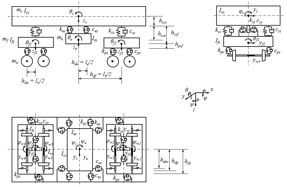
The schematic diagram of an MDOF DVA is shown in Fig. 1. The lower object is the main vibration system, and the upper object is the assistant mass as a DVA. Both the main system and the assistant mass are regarded as 6-DOF bodies. The assistant mass is connected to the main system through four points by elastic mounts. Four points under the main system are installed at the earth coordinates by elastic elements. Based on the structural model, mathematical equations are established to analyze the vibration absorption effect of the DVA on the main system.
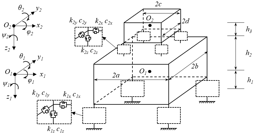
By using the matrix assembly method (Zhou, 2012), the mathematical differential equations of the multi-DOF DVA structural model can be obtained as follows:
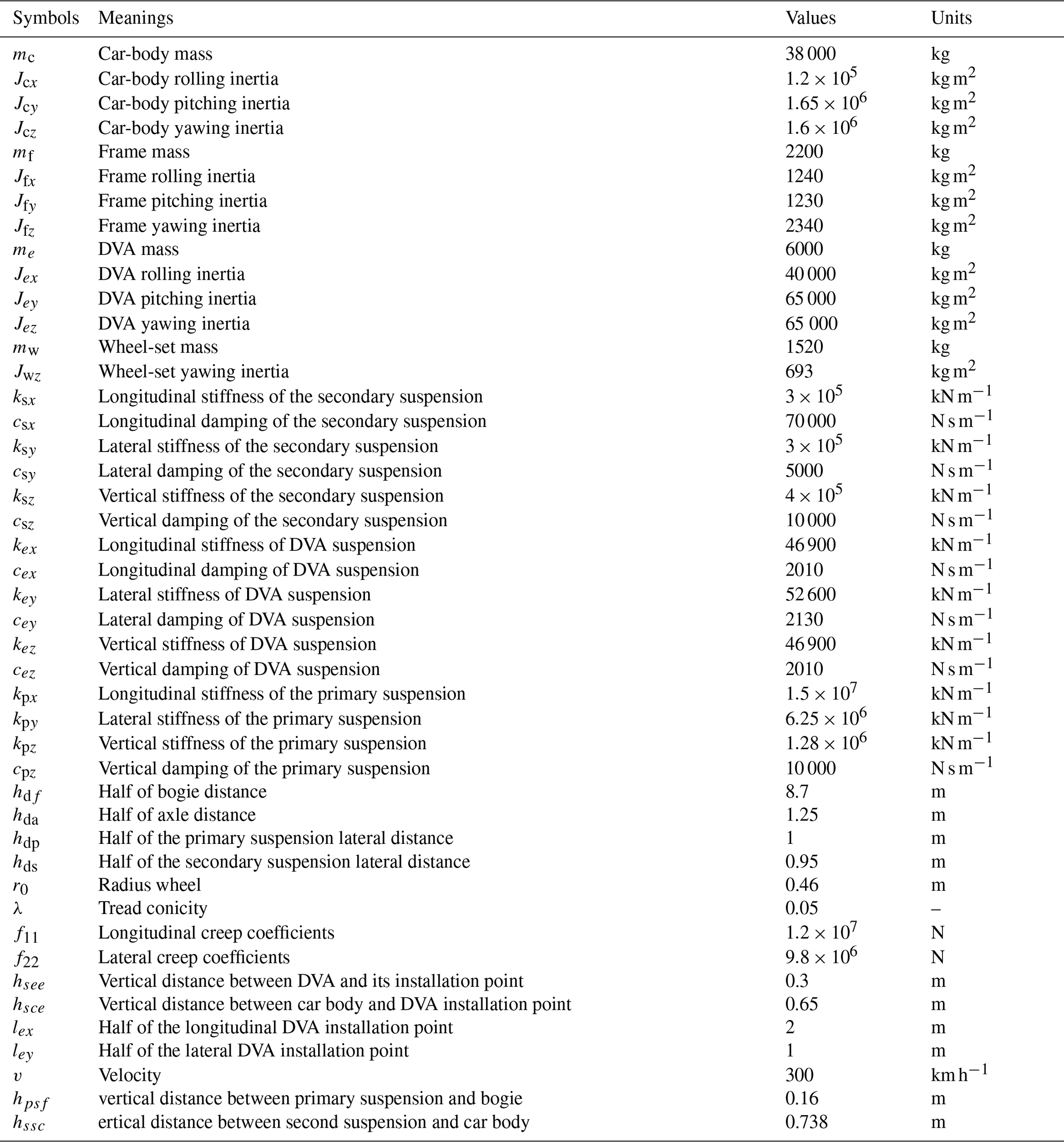
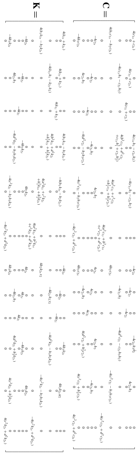
The symbols, meanings, and default values involved in the equations are shown in Appendix Table A1. By writing the above equation into a compact form, the following equation is obtained:
where . M, C, and K are the mass matrix, damping matrix, and stiffness matrix of the system, respectively, which are shown in Appendix C. With the character of the stiffness matrix K, the vertical motion and yaw of the system are completely decoupled from the movements in the other directions. By combing Eqs. (3) and (9), the DVA of vertical motion can be obtained according to the design principle of a single degree of freedom DVA (Seto, 2013). By the same principle, the yaw DVA can be obtained from Eqs. (6) and (12). Similarly, the remaining 4 degrees of freedom of the assistant system can also be designed as a dynamic vibration absorber of the main system theoretically.
2.2 Vibration shape and frequency analysis of the main system
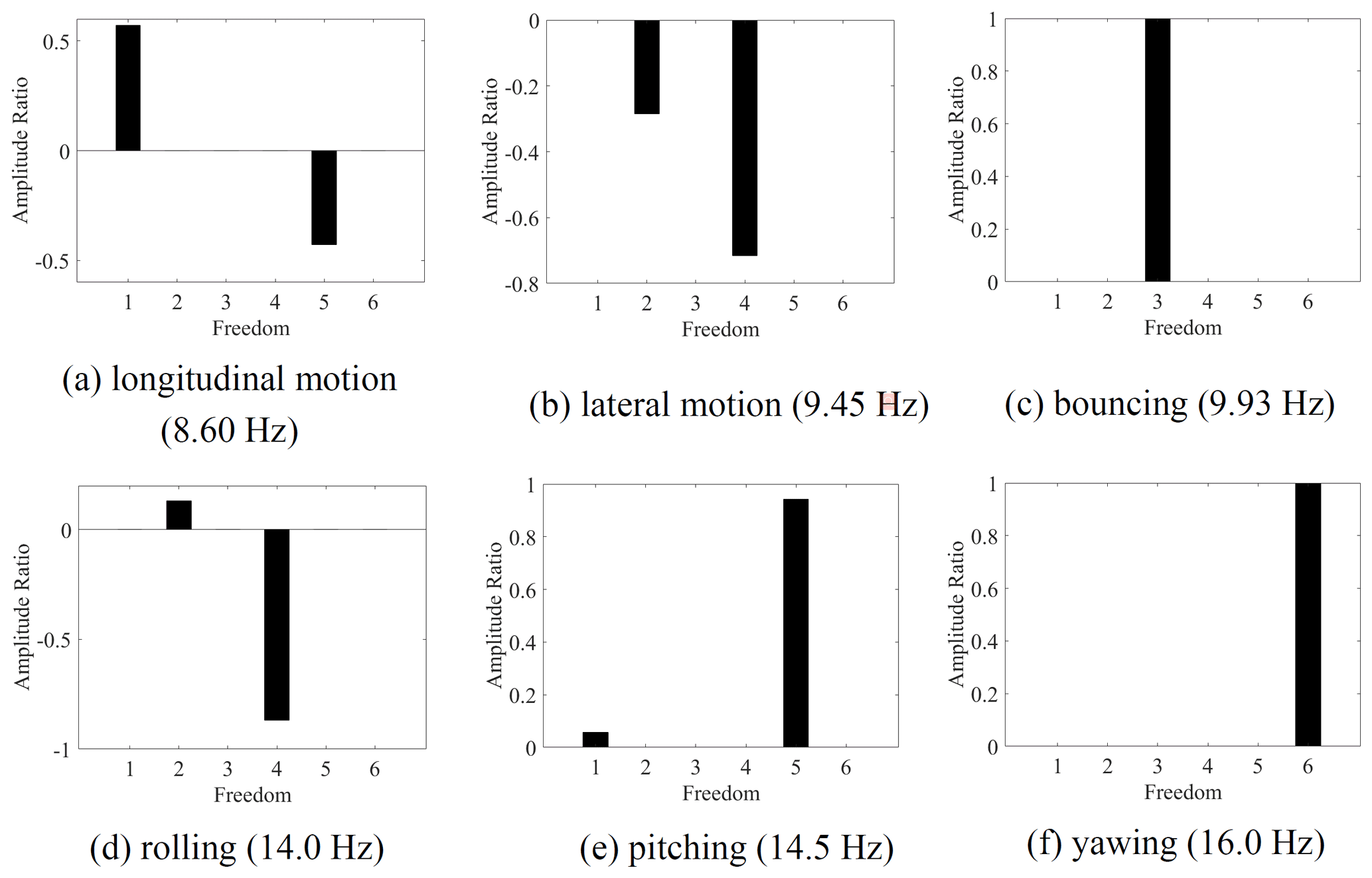
To obtain the design target frequency of the DVA, it is necessary to analyze the natural frequency of the main system in each degree of freedom without the assist system. A 6-DOF equation describing the vibration of the main system can be obtained by removing the assist system in Fig. 1. The natural vibration frequencies of the main system and the corresponding vibration shape (Xia et al., 2019) are shown in Fig. 2. From that, the lateral motion (the second vibration shape) is coupled vibration with rolling mode (the fourth vibration shape), and the longitudinal motion (the first vibration shape) is coupled vibration with pitching mode (the fifth vibration shape).
2.3 Parameter design and optimization of MDOF DVA
According to the design principle of a single DVA based on acceleration (Seto, 2013), the natural frequency of the MDOF DVA can be set as Eq. (14):
where is the natural frequency of the DVA of each DOF. μi is the mass ratio or inertia ratio of the DVA to the main system. The undamped natural frequency of the MDOF DVA without the consideration of couple vibration can be expressed as Eq. (15):
It can be noticed that the natural frequency of all DOFs is decided by six parameters, i.e., k2x, k2y, k2z, h3, c, and d. Therefore, an MDOF DVA that absorbs the vibrations of the main system in 6 DOFs can be designed based on the natural frequency in each DOF of the assist system. However, the six parameters are related to each other. Some parameters may be unreasonable when the frequency is selected as the design target. For example, due to space constraints, the geometric parameters h3,c, and d need to be designed within a certain range. To ensure the stability of the system, the stiffness parameters k2x, k2y, and k2z cannot be negative.
The acceleration frequency response function (FRF) is obtained to evaluate the vibration absorption performance of the MDOF DVA, as shown in Eq. (16).
where H(ω) is the acceleration FRF, and De is the excitation input matrix, which is shown in Appendix D. Φ is the input position matrix; ω is the angular frequency. The input position matrix is different when calculating the acceleration FRF of different degrees of freedom. For longitudinal motion FRF, the expression of the input position matrix is .
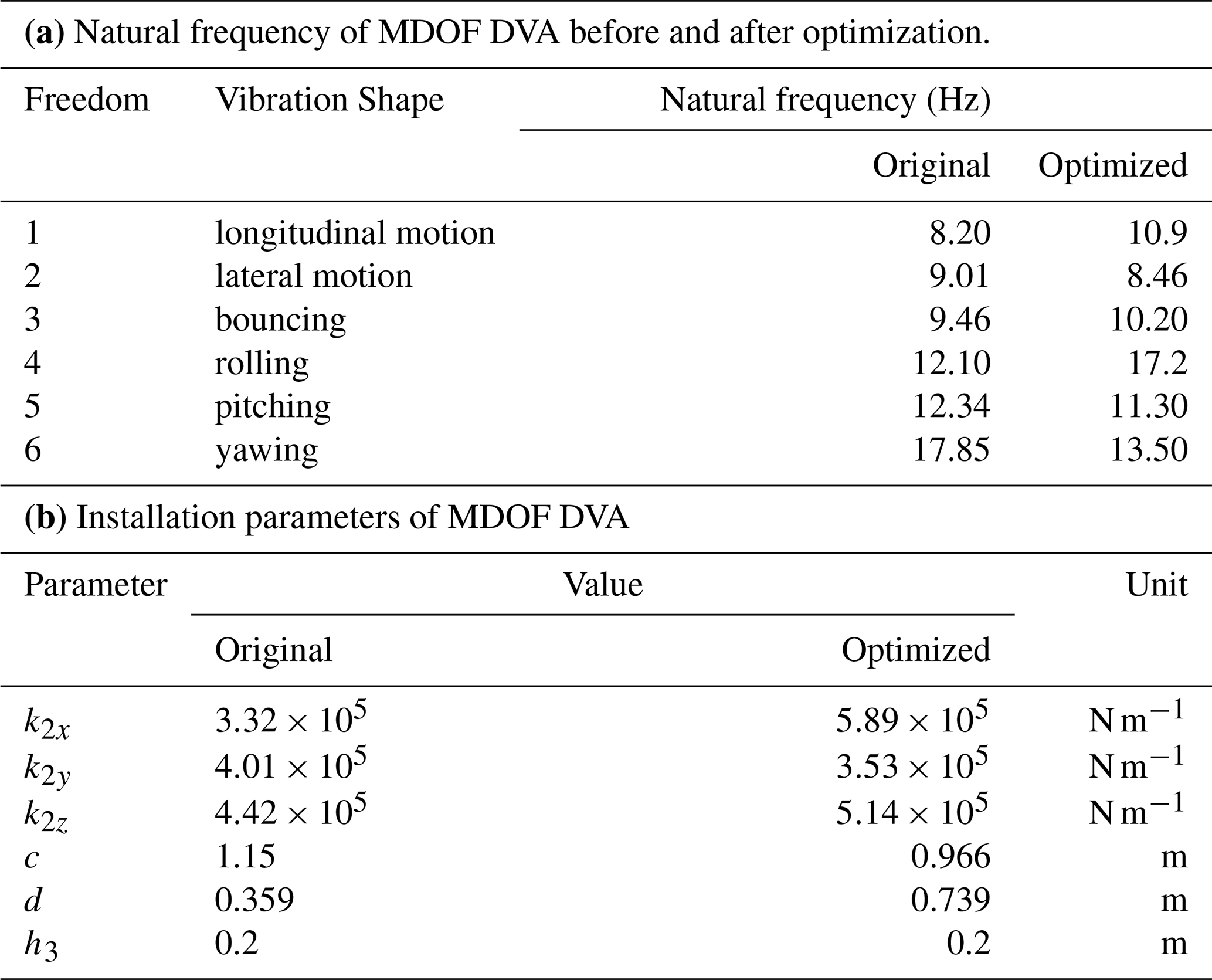
The natural frequency and installation parameters of the MDOF DVA can be calculated by Eqs. (14)–(15) and the natural frequency of the main system which is shown in Fig. 2. However, the result calculated by this method will appear a complex result, which is not reasonable. Therefore, here we set h3 equal to 0.2 m and calculate the natural frequency of all the DOFs except for yawing by Eq. (14). Then, the installation parameters of MDOF DVA can be obtained as Table 1b. After that, the natural frequency of yawing can be calculated according to Table 1b. The original natural frequency of the MDOF DVA is shown in Table 1a.
The acceleration FRFs of each DOF of the main system are calculated by Eq. (16), as shown in Fig. 3. The damping ratio with a value of 0.06 of the MDOF DVA is selected, and the installation stiffness is determined by the natural frequency. In Fig. 3, the dashed line stands for the acceleration FRFs of the main system without MDOF DVA, and the dash-dotted line is the calculation result with the original parameters of the MDOF DVA. As can be seen from that, the vibration of the longitudinal motion, bouncing, pitching and yawing has a certain but not optimal effect of vibration absorption after using the original MDOF DVA. In contrast, the vibration of lateral motion and rolling has little effect, due to the unconsidered damping of the main system in the MDOF DVA parameter design and the coupling vibration between lateral motion and rolling vibration.
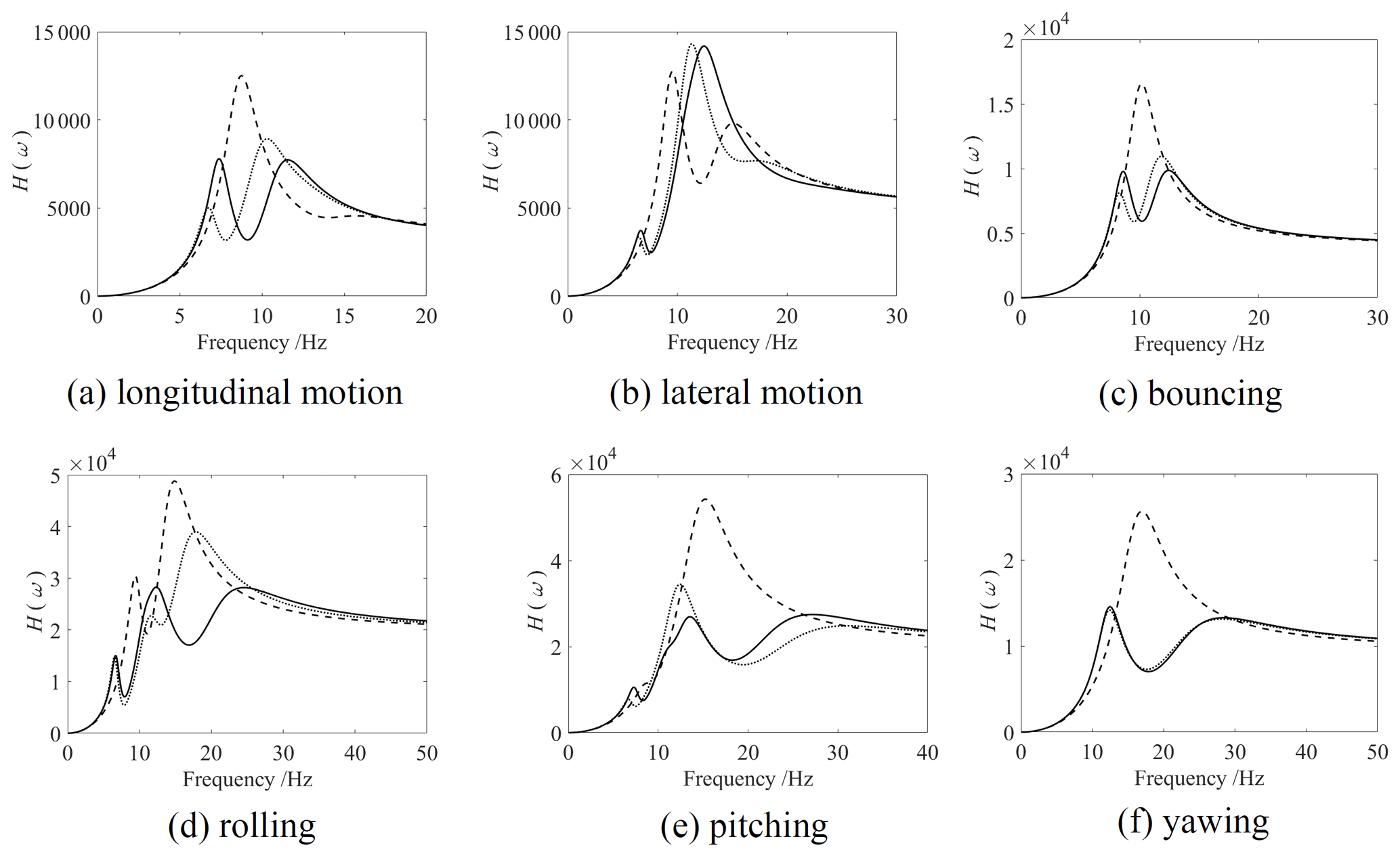
Figure 3Acceleration FRF of the main system. Dashed line: without MDOF DVA; dotted line: with original MDOF DVA; solid line: with optimized MDOF DVA.
Based on the original MDOF DVA parameters, a genetic algorithm is utilized to optimize the natural frequency in each DOF of MDOF DVA. The objective function and constraints can be set as
where Hi stands for the acceleration FRF of each DOF of the main system, and αi is a weight coefficient.
By setting αi=1 (i=1–6), the optimized natural frequency and installation parameters of MDOF DVA are calculated, which are shown in Table 1a and b, respectively. The optimized acceleration FRFs of the main system are shown in Fig. 3 with the solid line. It illustrates that the optimal vibration absorption effects of longitudinal motion, bouncing, rolling, pitching are achieved after optimization. Compared with the results without MDOF DVA, the peak values of the 4 DOFs are declined by 37.7 %, 40.5 %, 42.1 %, and 49.4 %, respectively. The amplitude of lateral motion increases due to its coupling vibration with rolling, and the optimization process of the genetic algorithm makes the FRF peak value of rolling greatly reduced, while the FRF peak value of lateral motion increases to a certain extent. The yawing vibration is not much different from the vibration absorption effect before optimization. This is due to the limitation of the parameters, which makes it difficult to further optimize the yawing vibration. As shown in Fig. 3, MDOF DVA can simultaneously absorb the vibration of multiple DOFs of the main system, but the existence of coupling vibration and the limitation of the parameters make it difficult to absorb all the vibration shapes at the same time.
3.1 Model establishment of a high-speed train
A high-speed train dynamic model is established to analyze the vibration suppression performance of the MDOF DVA for the car body, the schematic diagram of which is shown in Fig. 4. The model has 28 DOFs that include four wheel sets which consider the lateral motion and yawing (4×2 DOFs), two bogies, one car body, and one MDOF DVA which considers lateral motion, bouncing, rolling, pitching, and yawing (5×4 DOFs). In the simulation analysis, it is assumed that the wheel set is close to the rail surface in the vertical direction, and the vertical irregular excitation is applied through the axle box (Zhou, 2012). The lateral irregularities are imposed by the wheel–rail linear contact relationship.
The completed dynamic model is shown in Appendix B. The parameters and their meanings in the model are shown in Appendix Table A2. By extracting the coefficients from the equations and writing the equations into a compact form, the following equation is obtained:
where Mt, Ct, and Kt are the mass matrix, damping matrix, and stiffness matrix of the vehicle system, respectively. Dw stands for excitation input matrix, and Yw stands for the track irregularity.
3.2 Vibration shape and frequency analysis of the high-speed train
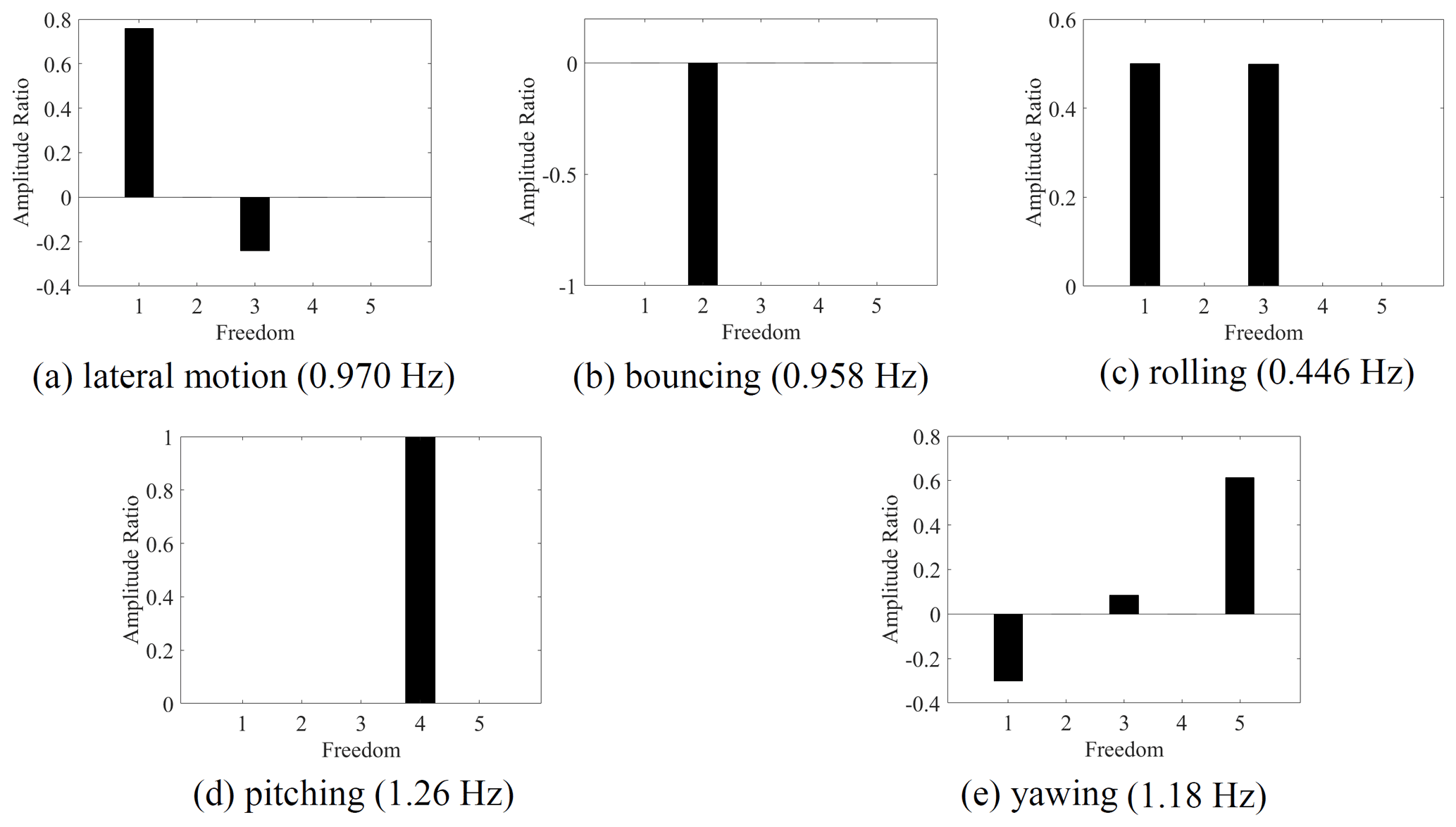
The vibration shape of the high-speed train without DVA is obtained for the frequency design of the MDOF DVA. As shown in Fig. 4, a high-speed vehicle model with 23 DOFs is established for eigenvalue and vibration shape analysis without DVA, and the results are shown in Fig. 5. It illustrates that the lateral motion is coupled vibration with rolling. When the two DOFs vibrate in the same direction, it is the upper core rolling, as shown in Fig. 5c; when they vibrate in the opposite direction, it is the lower core rolling, as shown in Fig. 5a. For the clarity of the subsequent description, considering the amplitude ratio of the coupled modes, the upper core rolling mode is regarded as rolling, and the lower core rolling mode is regarded as lateral motion.
3.3 Track irregularity input
Track irregularity is the main excitation of the vehicle system during the operation of the high-speed train. Track irregularity excitation is input to the vehicle system through the wheel sets, and a time delay exists between each wheel set. The acceleration power spectral density (PSD) of each DOF is applied to evaluate the vibration of the car body for investigating the vibration absorption performance of MDOF DVA. The calculate method is
where stands for conjugate matrix, (⋅)T stands for transpose matrix, S is the acceleration PSD of each DOF of the car body, and ψ is a coordinate transformation matrix. Y is related to vehicle system parameters, excitation input matrix, and input time delay. The expression of Y is
where Dw is the excitation input matrix, Td is the time delay matrix, and SFF(ω) is the PSD of track irregularity. The high-speed track irregularity is adopted in the model (Zhou, 2012), the vertical and lateral PSD of which are as follows:
where Ω is spatial circular frequency (rad m−1), Av is m rad−1, Aa is m rad−1, Ωc is 0.8246 rad m−1, and Ωr is 0.206 rad m−1.
3.4 Optimal design of MDOF DVA for the high-speed train
A genetic algorithm is utilized to optimize the parameters of the MDOF DVA. Due to the space limitation of the chassis of the car body, here the original parameters of the MDOF DVA do not need to be calculated based on Eq. (15) and Table 1, but they set the parameter constraint range and use a genetic algorithm to optimize the parameters of the MDOF DVA. Considering that the installation height of the DVA is usually close to the bottom of the car body, the installation height parameter hsee can be set to a constant value. Limited by installation space, the half of the longitudinal lex and lateral spans ley and the installation stiffness kex, key, kez of the three directions need to set a constraint range. The objective function and constraints can be set as
where Si stands for the power spectrum density (PSD) of each DOF of the car body, and βi is a weight coefficient.
The optimized natural frequency and the installation parameters of the MDOF DVA can be obtained according to the optimization steps as shown in Table 2a and b, respectively.
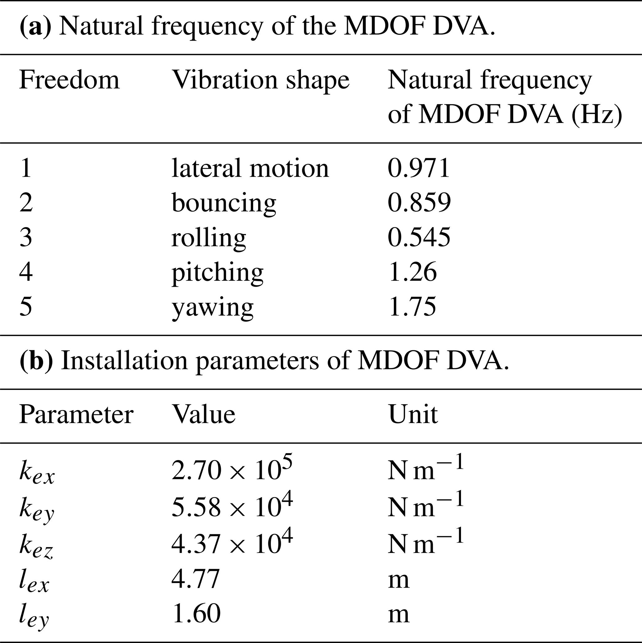
Figure 6 shows the comparison of the acceleration PSD of the car body with the optimized MDOF DVA and without DVA. In the simulation, the installation damping ratio of the DVA is set as 0.06. This is because the damping ratio of natural rubber is 0.05–0.075 (Sun, 2016), and if the damping ratio is too high, the rubber is easy to be heated and the process of aging and creep will be accelerated. Figure 6a and b illustrate that after the MDOF DVA is applied, the maximum of the lateral motion and bouncing acceleration PSD change from one to two equal values, indicating that the lateral motion and bouncing modes achieved the optimal vibration absorption. The maximum of the lateral motion decreases from 0.045 (m s−2)2 Hz−1 to 0.0035 (m s−2)2 Hz−1, with a reduction of 92.2 %. The maximum of the bouncing mode decreases from 0.041 (m s−2)2 Hz−1 to 0.0063 (m s−2)2 Hz−1, with a reduction of 84.6 %. It can be seen from Fig. 6c that the rolling vibration mode has a certain vibration absorption effect, but it is not optimal. It lies a cause that the rolling vibration is coupled with lateral motion, which makes it difficult to optimize both simultaneously. Figure 6d demonstrates that the pitching vibration is well suppressed. Figure 6e indicates that the yawing mode has no obvious vibration absorption effect because it is difficult to design the natural frequency of the yawing mode to the optimal vibration-absorbing due to the limitation of the parameter constraint range. All in Fig. 6 show that the MDOF DVA can absorb multiple vibration modes of the car body at the same time, and some of them can achieve optimal vibration absorption. However, the limitation of parameter constraint range and coupling vibration makes it impossible to design all vibration modes at the same time as the optimal DVA of the car body.
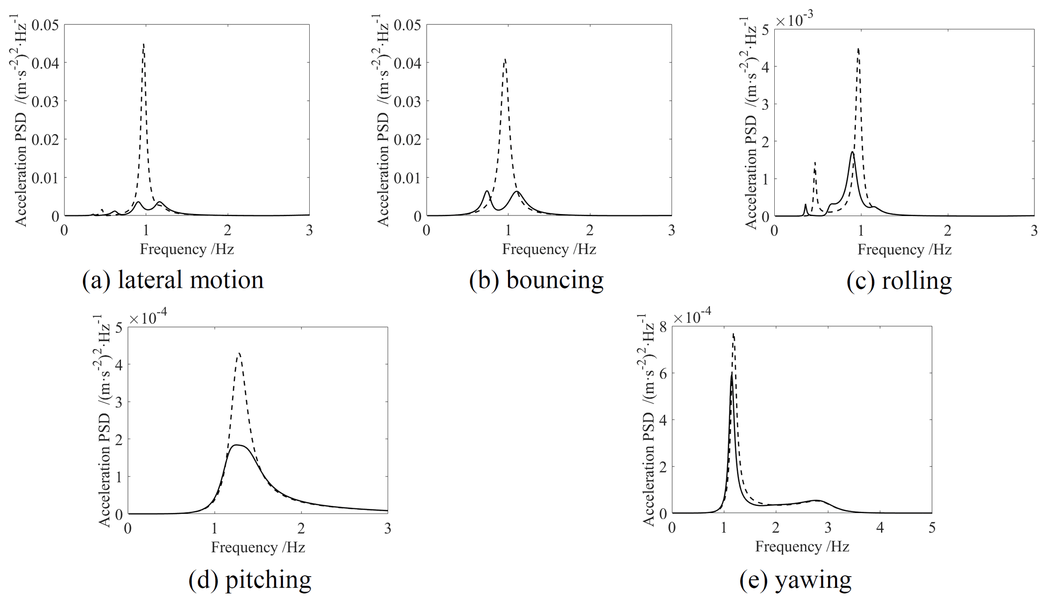
Figure 6PSD of each DOF of the car body. Dashed line: without MDOF DVA; solid line: with optimized MDOF DVA.
With linear elastic isolators as the installation mounts of the MDOF DVA, the relationship of parameters of a DVA is written as
where m, kz, fz, and δst are mass, vertical installation stiffness, installation frequency, and static deflection respectively; n is the mounting number, which is set as 4 in this research. Equation (24) shows that the vertical installation frequency directly determines the vertical stiffness and the static deflection. The static deflection would be extremely large if the vertical installation frequency were relatively low. According to the main vertical vibration frequency of the MDOF DVA with a value of 0.859 Hz, the static deflection is 0.337 m with the linear elastic isolators. It is obvious that such a large static deflection is difficult to apply in engineering.
Hence, a high static and low dynamic (HSLDS) mount based on a cam–roller–spring mechanism is proposed. The schematic figure of the HSLDS mount is shown in Fig. 7. It is composed of a negative stiffness structure and a positive stiffness spring. The negative stiffness structure is composed of roller guide support, lateral springs, and rollers. The vertical dynamic stiffness of the HSLDS mount is given by the sum of the dynamic stiffness of the negative stiffness structure and the vertical spring. In addition, a height adjuster is set to arrange that the midpoint of the curved surface is in contact with the roller when the isolated object is placed in equilibrium. Different from the design of a QZS isolator in Sun et al. (2019a), this type of mount is intended for an HSLDS mount with low positive stiffness near the equilibrium position in this research.
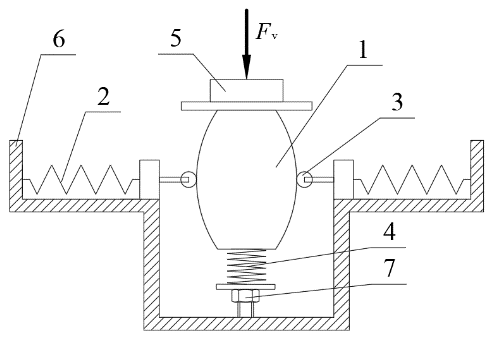
Figure 7Schematic design of the HSLDS mount based on target force curve (1 – roller guide support, 2 – lateral spring, 3 – roller, 4 – vertical spring, 5 – isolated object, 6 – fitting seat, 7 – height adjuster).
The left and right guides are assumed to be symmetrical, and the force analysis of the left guide is used as an example, as shown in Fig. 8. This produces a negative stiffness in the vertical direction when the roller guide surface is convex, as shown in Fig. 8a. In this case, when the isolated object moves upwards, and the vertical component of the force exerted by the rollers is also upward, which corresponds to a negative stiffness.
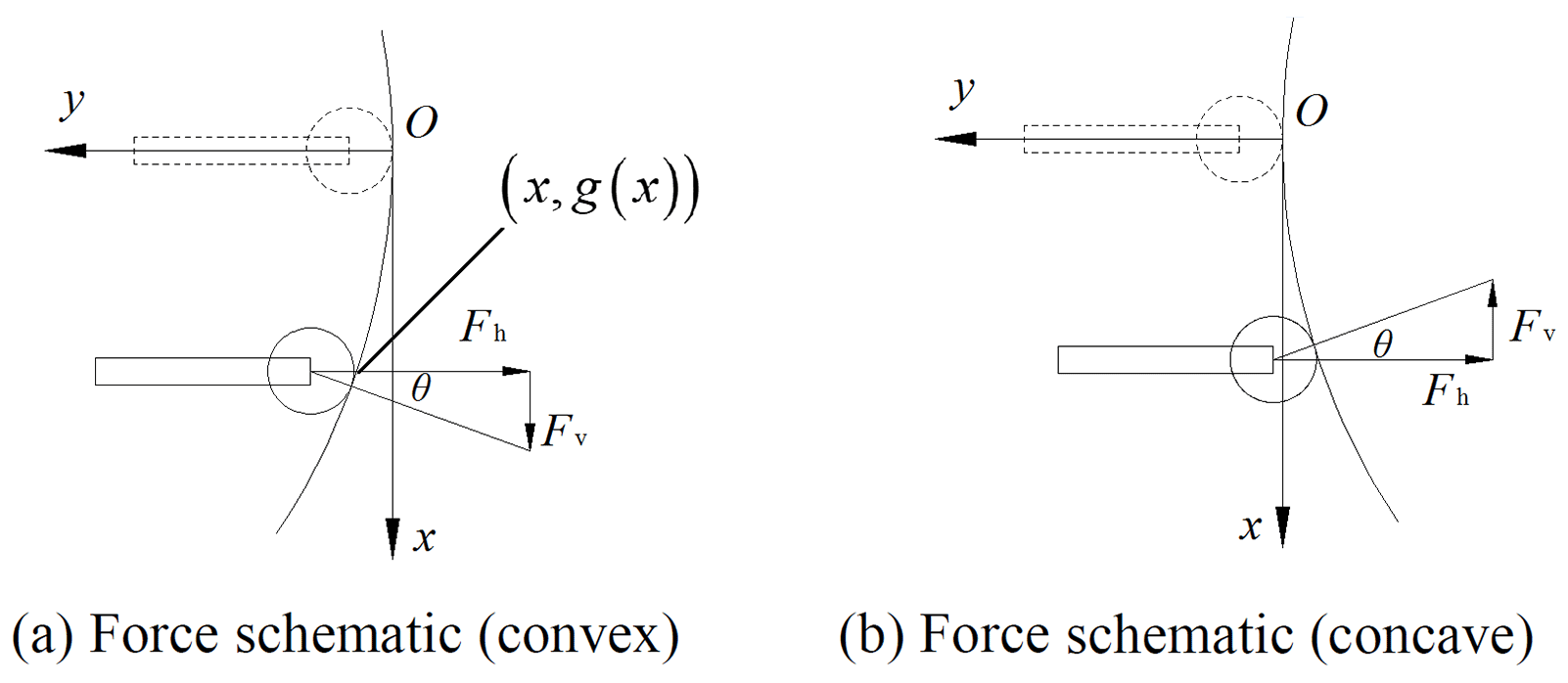
The shape of the guide surface is defined by the function y=g(x). It can be assumed that the effect of the roller radius on the system is negligible. As shown in Fig. 8a, the contact point is (x, g(x)) when the deflection of the isolated object from the equilibrium position is x (g is negative in Fig. 8a). The gradient at the contact point is g′(x), which is equal to tan θ. The spring deformation can be expressed as Δl+g(x), where Δl is the initial pre-deformation of the lateral springs. Based on the force analysis, the force of the mount in the vertical direction can be expressed as
where , kv is the stiffness of the vertical spring, and is the stiffness of the lateral spring for one side. Rearranging Eq. (25) and integrating both sides, it can be obtained as follows:
where C is a constant. According to the desired equilibrium condition, the boundary conditions of Eq. (26) are f (0) =g(0) = 0 and C= 0. For a specific target force curve, the corresponding roller slide curve can be obtained by numerical calculation. Equation (26) can be regarded as a quadratic polynomial equation in g(x), and the solution can be obtained as
It can be verified that the same result can be acquired according to the force analysis of Fig. 8b.
According to the installation parameters of the optimized MDOF DVA in Table 2, the vertical stiffness of which is 4.37×10⁴ N m−1. To obtain a component with a high static stiffness while the dynamic stiffness is kez near the equilibrium position, the target force curve can be set as
By differentiating Eq. (28), the stiffness of the HSLDS mount can be obtained as
By assuming the static deflection as δst , and setting , the following equation can be obtained when the displacement of the suspension object is equal to its static deflection:
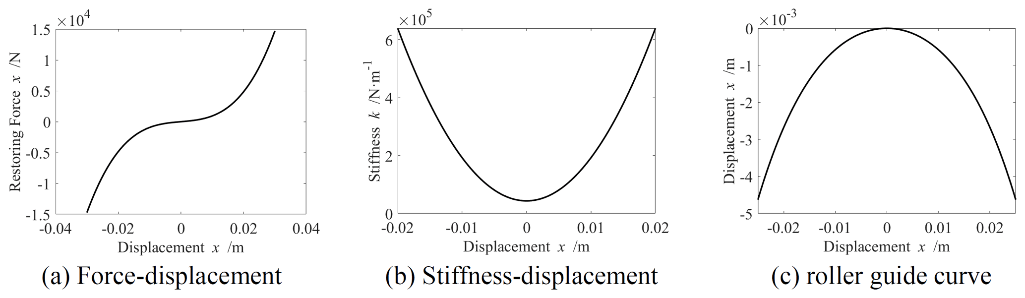
By setting δst= 0.03 m, the mechanical and stiffness characteristics of the HSLDS mount are obtained as Fig. 9a and b, respectively. It can be seen from Fig. 9a that when the displacement is 0.03 m, and the restoring force of the HSLDS mount is mg . Figure 9b illustrates that the stiffness of the HSLDS mount is kez at the equilibrium position. The roller guide curves of the HSLDS mount obtained according to Eq. (27) for Δl=0.1 m, kh=kv, is shown in Fig. 9c. It can be found that the use of HSLDS mount as the installation component of MDOF DVA can reduce the static deflection from 0.337 to 0.03 m, with a reduction of 91 %.
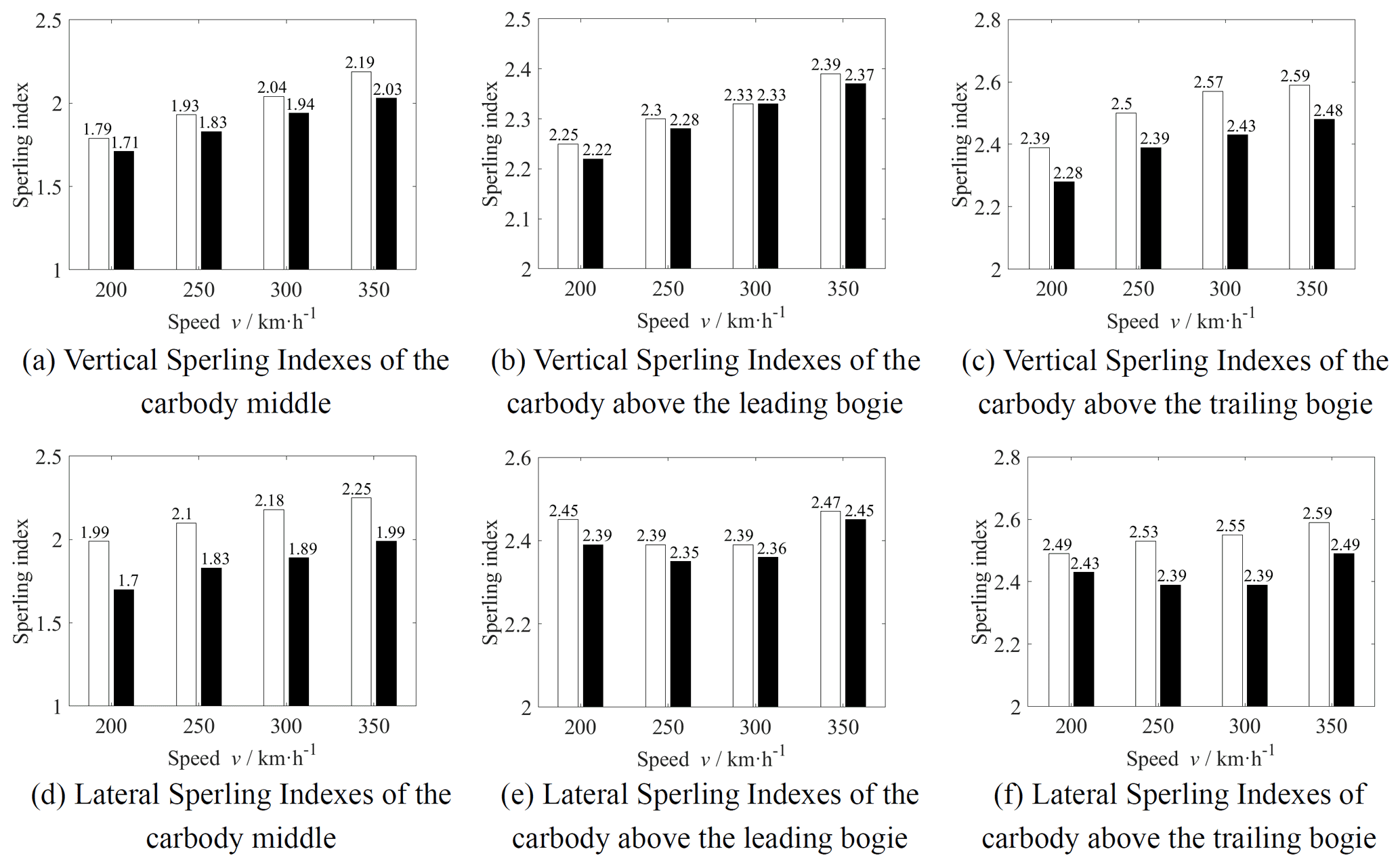
Figure 10Sperling indexes of different connection methods (white column – with MDOF DVA; black column – without DVA).
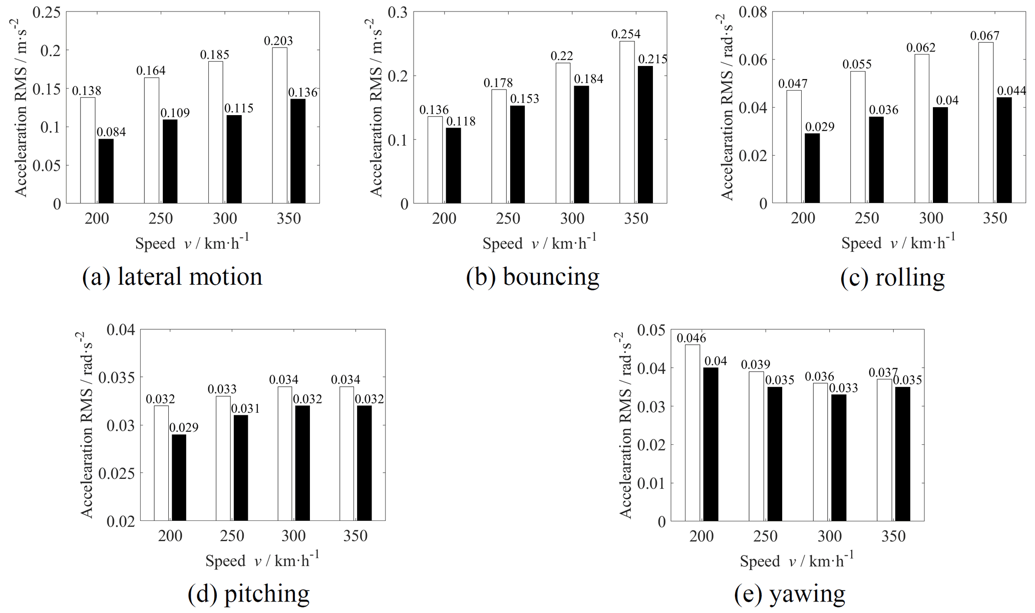
Figure 11Acceleration rms values of different connection methods (white column – with MDOF DVA; black column – without DVA).
In Sect. 3, the mounting component of the MDOF DVA is a linearly elastic spring. To verify the vibration absorption performance of the MDOF DVA when the installation components are HSLDS mounts, a nonlinear simulation experiment is applied in this section.
A nonlinear time-domain high-speed train model is established by MATLAB/SIMULINK software based on Fig. 4. Using the object-oriented modeling method, the vehicle dynamics system components can be divided into four categories (Zhou, 2012): (1) structure, (2) suspension, (3) wheel–rail contact, and (4) track input. The structure category includes one car body, one MDOF DVA, two bogies, and four wheel sets. The suspension category is eight primary suspensions, four secondary suspensions, and four springs for MDOF DVA. The wheel–rail contact category considers the linear wheel–rail contact relationship. Track input is a time-domain spectrum that is translated according to the PSD of high-speed track irregularity. The nonlinear force characteristics of the HSLDS mount are built in the simulation model by interpreted function.
The Sperling indices (Deng et al., 2019) of the car body with and without MDOF DVA are shown in Fig. 10 at different operating speeds. It can be seen from the figure that the vertical and lateral Sperling indices at the car body middle and above the trailing bogie have certain improvements after MDOF DVA is applied. Comparing the calculation results of the car body with MDOF DVA installed by HSLDS mounts and without DVA at the speed of 350 km h−1, the vertical Sperling index at the car body middle and above the trailing bogie decreased by 0.16 and 0.11, respectively, and the lateral Sperling index at the same positions decreased by 0.26 and 0.10, respectively. The vertical and lateral Sperling indexes of the car body above trailing bogie exceed 2.5 when the operating speeds are over 250 km h−1, which is not acceptable for the operation of high-speed trains. By the application of MDOF DVA, the Sperling indices at this position are reduced to below 2.5, which means that the ride quality level is excellent.
The acceleration rms values of each DOF of the car body with and without MDOF DVA are shown in Fig. 11 at different operating speeds. It can be seen from the figures that the vibrations of all DOFs of the car body are suppressed by MDOF DVA. Among these, the vibration suppression performance on lateral motion is the best, the acceleration rms of which is reduced by 39 %, 34 %, 38 %, and 33 % at operation speeds of 200, 250, 300, and 350 km h−1, respectively. When the operating speed is 350 km h−1, the vibration acceleration rms of bouncing, rolling, pitching, and yawing is reduced by 15 %, 34 %, 6 %, and 5 %, respectively.
Summarizing Figs. 10 and 11, it can be found that the MDOF DVA installed under the car body by using HSLDS mounts can simultaneously achieve dynamic vibration absorption of the car body in 5 degrees of freedom. Affected by the limitation of parameters and the coupled vibration, the vibration absorption performance of lateral motion, bouncing, and rolling have a significant effect, while pitching and yawing are not very obvious. The vibration of the car body is suppressed, and the ride quality is improved when the MDOF DVA is applied on a high-speed train.
In this paper, an MDOF DVA is proposed to suppress the rigid vibration of high-speed trains. The main conclusions are shown as follows.
-
A 12-DOF model of two objects is established, and the vibration absorption mechanism of the MDOF DVA is introduced. By combining the design method of classical single DVA and genetic algorithm, it found that the MDOF DVA can absorb the longitudinal motion, bouncing, rolling, pitching, and yawing vibrations of the main system simultaneously.
-
A high-speed train dynamic model is established, and an MDOF DVA that absorbs the different vibrations simultaneously is designed. With the MDOF DVA, the lateral motion, bouncing, and pitching can achieve the best vibration absorption performance at the same time. For the installation of MDOF DVA with the low vertical dynamic stiffness, an HSLDS mount is designed based on a cam–roller–spring mechanism. Compared with the linear elastic spring, the equipment can obtain the extremely low static deflection with a drop of 91 % and even the same dynamic stiffness near the equilibrium position.
-
A high-speed train dynamic model with the consideration of the nonlinearity of the stiffness of the installed components is established. By using a time-integration simulation experiment, the vibration suppression performance of the MDOF DVA with the installation of the HSLDS mount is verified. The results show that MDOF DVA can effectively absorb the rigid vibration of the car body and improve the ride quality of the high-speed train.

The equations of motion for the first wheel set, first bogie frame, car body, and MDOF DVA in the high-speed train dynamic model are written as
The mass matrix M, damping matrix C, and stiffness matrix K in Eq. (13) are written as follows:
The excitation input matrix D in Eq. (16) is written as follows:
All of the code used in this paper can be obtained from the corresponding author upon request.
All of the data used in this paper can be obtained from the corresponding author upon request.
YS and JZ designed the study and wrote the manuscript. DG conducted the simulation research. YJ provided guidance on the writing.
The contact author has declared that neither they nor their co-authors have any competing interests.
Publisher's note: Copernicus Publications remains neutral with regard to jurisdictional claims in published maps and institutional affiliations.
This research has been supported by the National Natural Science Foundation of China (grant no. 51805373), the National Postdoctoral Program for Innovative Talents (grant no. BX20200240), and the China Postdoctoral Science Foundation (grant no. 2020M671207).
This paper was edited by Dario Richiedei and reviewed by two anonymous referees.
Alabuzhewv, P., Gritchin, A., Kim, L., Migirenko, G., Chon, V., and Stepanov, P.: Vibration protecting and measuring systems with quasi-zero stiffness, Taylor & Francis Group, New York, ISBN 0-89116-811-7, 1989.
Carrella, A., Brennan, M. J., Waters, T. P., and Lopes, V.: Force and displacement transmissibility of a nonlinear isolator with high-static-low-dynamic-stiffness, Int. J. Mech. Sci., 55, 22–29, https://doi.org/10.1016/j.ijmecsci.2011.11.012, 2012.
Danh, L. T. and Ahn, K. K.: Active pneumatic vibration isolation system using negative stiffness structures for a vehicle seat, J. Sound Vib., 333, 1245–1268, https://doi.org/10.1016/j.jsv.2013.10.027, 2014.
Deng, C. X., Zhou, J. S., Thompson, D. J., Gong, D., Sun, W. J,. and Sun, Y.: Analysis of the consistency of the Sperling index for rail vehicles based on different algorithms, Vehicle Syst. Dyn., 59, 313–330, https://doi.org/10.1080/00423114.2019.1677923, 2019.
Elias, S. and Matsagar, V.: Research developments in vibration control of structures using passive tuned mass dampers, Annu. Rev. Control, 44, 129–156, https://doi.org/10.1016/j.arcontrol.2017.09.015, 2017.
Gong, D., Zhou, J. S., and Sun, W. J.: On the resonant vibration of a flexible railway car body and its suppression with a dynamic vibration absorber, J. Vib. Control., 19, 649–657, https://doi.org/10.1177/1077546312437435, 2013.
Gong, D., Zhou, J. S., Sun, W. J., Sun, Y., and Xia, Z. H.: Method of multi-mode vibration control for the carbody of high-speed electric multiple unit trains, J. Sound. Vib., 409, 94–111, https://doi.org/10.1016/j.jsv.2017.05.010, 2017.
Lee, C. M., Goverdovskiy, V. N., Sim, C. S., and Lee, J. H.: Ride comfort of a high-speed train through the structural upgrade of a bogie suspension, J. Sound Vib., 361, 99–107, https://doi.org/10.1016/j.jsv.2015.07.019, 2016.
Meng, L. S., Sun, J. G., and Wu, W. J.: Theoretical Design and Characteristics Analysis of a Quasi-Zero Stiffness Isolator Using a Disk Spring as Negative Stiffness Element, Shock Vib., 2015, 1–19, https://doi.org/10.1155/2015/813763, 2015.
Ren, M. Z.: A variant design of the dynamic vibration absorber, J. Sound Vib., 245, 762–770, https://doi.org/10.1006/jsvi.2001.3564, 2001.
Richiedei, D., Tamellin, I., and Trevisani, A.: Beyond the tuned mass damper: a comparative study of passive approaches to vibration absorption through antiresonance assignment, Arch. Comput. Method E, 29, 519–544, https://doi.org/10.1007/s11831-021-09583-w, 2022.
Seto, K.: Dynamic Vibratin Absorber and its Applications, Machine Press, Beijin, ISBN 9787111415763, 2013.
Shi, H. L., Luo, R., Wu, P. B., Zeng, J., and Guo, J. Y.: Application of DVA theory in vibration reduction of carbody with suspended equipment for high-speed EMU, Sci. China Technol. Sci., 57, 1425–1438, https://doi.org/10.1007/s11431-014-5558-5, 2014.
Sun, Y., Gong, D., and Zhou, J. S.: Study on Vibration Reduction Design of Suspended Equipment of High Speed Railway Vehicles, J. Phys. Conf. Ser., 744, 012212, https://doi.org/10.1088/1742-6596/744/1/012212, 2016.
Sun, Y., Gong, D., Zhou, J. S., Sun, W. J., and Xia, Z. H.: Vibration control of high-speed trains self-excitation under-chassis equipment by HSLDS vibration isolators, J. Mech. Sci. Technol., 33, 65–76, https://doi.org/10.1007/s12206-018-1207-4, 2019a.
Sun, Y., Gong, D., Zhou, J. S., Sun, W. J., and Xia, Z. H.: Low frequency vibration control of railway vehicles based on a high static low dynamic stiffness dynamic vibration absorber, Sci. China Technol. Sc., 62, 60–69, https://doi.org/10.1007/s11431-017-9300-5, 2019b.
Thompson, D. J.: A continuous damped vibration absorber to reduce broad-band wave propagation in beams, J. Sound Vib., 311, 824–842, https://doi.org/10.1016/j.jsv.2007.09.038, 2008.
Tomioka, T. and Takigami, T.: Reduction of bending vibration in railway vehicle carbodies using carbody-bogie dynamic interaction, Vehicle Syst. Dyn., 48, 467–486, https://doi.org/10.1080/00423114.2010.490589, 2010.
Xia, Z. H., Zhou, J. S., Gong, D., Sun, W. J., and Sun, Y.: On the modal damping abnormal variation mechanism for railway vehicles, Mech. Syst. Signal Pr., 122, 256–272, https://doi.org/10.1016/j.ymssp.2018.12.015, 2019.
Zhou, J. S.: Vibration and control in railway vehicles, China Railway Publishing House, Beijing, ISBN 9787113150143, 2012.
Zhou, J. X., Wang, X. L., Xu, D. L., and Bishop, S.: Nonlinear dynamic characteristics of a quasi-zero stiffness vibration isolator with cam-roller-spring mechanisms, J. Sound Vib., 346, 53–69, https://doi.org/10.1016/j.jsv.2015.02.005, 2015.
- Abstract
- Introduction
- Mechanism of MDOF DVA based on acceleration
- Establishment and analysis of a high-speed train dynamic model
- Design of high static and low dynamic stiffness mounts
- Simulation experiment
- Conclusions
- Appendix A
- Appendix B
- Appendix C
- Appendix D
- Code availability
- Data availability
- Author contributions
- Competing interests
- Disclaimer
- Financial support
- Review statement
- References