the Creative Commons Attribution 4.0 License.
the Creative Commons Attribution 4.0 License.
 | 17 Mar 2022
Design and test of a positioning system for a greenhouse electric micro-tiller based on ultra-wideband
Ying Lin
Qian Chen
Haijun Zhang
Ye Ma
Wenlian Zeng
Guojun Wei
Hongxiang Wang
A positioning system for ultra-wideband (UWB) electric micro-tillers suitable for complex greenhouse environments was designed as the basis for realizing unmanned micro-tillers to address the problem of the frequent safety accidents of existing micro-tillers. First, the positioning base station and tag were designed on the basis of the STM32 and DW1000 chip hardware. The real-time coordinate display of the micro-tiller in the greenhouse could also be realized with the design of the upper computer software. Then, the realization method of the positioning function, including the analysis of time difference of arrival (TDOA) and two-way ranging (TWR) positioning methods, and the selection of the best Taylor positioning algorithm through a MATLAB simulation were studied to reduce the influence of noise and measurement errors on measurement accuracy. Finally, a positioning system accuracy test was conducted. Test results revealed that the maximum positioning error of the micro-tiller positioning system is no more than 6 cm, and the average error is 4.4 cm. The optimized positioning error is reduced by 10.2 %, considering that the influence of the base station location on the accuracy. The positioning system of the greenhouse electric micro-tiller designed in this paper demonstrates a stable performance and positioning accuracy to meet the needs of greenhouse rotary tillage operations. This system has certain theoretical importance and reference value for the development of precise positioning technology for working tools in the greenhouse and the further realization of unmanned rotary tillage operations.
- Article
(5135 KB) - Full-text XML
- BibTeX
- EndNote


The miniature rotary tiller can be used for rotary tillage in small, scattered fields and greenhouses, which not only improves the mechanization level of facility agriculture but also substantially reduces the labour intensity of farmers (Du et al., 2019). Most of the existing micro-tillers rely on close-range manual operation, and the operators encounter frequent safety accidents due to long-term direct contact with the rotary tillage machinery and tremor fatigue (Zeng et al., 2020; Zhao et al., 2016). In recent years, with the application and development of unmanned driving technology, remote unmanned rotary tillage operations in greenhouses have become a breakthrough to solve the above-mentioned mini-tiller safety problems (Chen et al., 2015; Zhang et al., 2021).
Unmanned rotary tillage operations can be realized through the combination of the ultra-wideband (UWB) positioning system and mature remote control technology (Yao et al., 2020). The global positioning system (GPS) is currently the most commonly used positioning system. Luo et al. (2009) developed an automatic navigation system for agricultural machinery based on a GPS that can achieve centimetre-level accuracy. Guo et al. (2013) designed an automatic operation control system for rice transplanter based on a GPS navigation system, which substantially reduced the speed control error. However, GPS is susceptible to factors, such as clouds and ground obstacles and weather, and is unsuitable for sheltered greenhouse environments. Ding et al. (2017) designed the motion controller of the BeiDou positioning field information acquisition platform, with three low-precision BeiDou positioning modules, and performed data fusion to obtain a positioning accuracy higher than that of a single-module car body. However, the cost of this platform is too high to be suitable for large-scale agricultural production promotion. Li et al. (2013) studied a positioning algorithm based on omnidirectional vision sensors, with an accuracy of approximately 15 cm. However, the accuracy and stability of the machine's vision positioning are considerably affected by environmental factors, such as weather and light.
Other indoor positioning technologies have emerged in recent years, including Bluetooth, Wi-Fi, Zigbee, ultrasound, and ultra-wideband (UWB). The Wi-Fi-based positioning technology has good anti-interference and penetration capabilities, but its accuracy only reaches a metre level. The positioning technology based on Bluetooth and Zigbee has poor anti-interference capability, and the accuracy can only reach a decimetre level. The theoretical positioning accuracy based on ultrasonic technology can reach a centimetre level, but its penetrating power is weak, and the sound wave energy is easily attenuated. Thus, this approach is also unsuitable for precise positioning in a complex environment in a greenhouse (Liu et al., 2022). UWB positioning technology has the advantages of high accuracy, low energy consumption, stable performance, simple design, low cost, convenient network node layout, and the absence of harsh requirements on the site environment. Thus, this technology is suitable for use in indoor environments, such as the greenhouse (Emadian et al., 2018; Guo, 2020).
Overall, UWB technology has advantages over other technologies, considering precise positioning in a greenhouse environment. This paper will focus on the design of the positioning system of the electric micro-tiller based on UWB in the complex greenhouse environment. First, the overall scheme of the system based on UWB technology and the design of software and hardware are comprehensively introduced. Then, the realization of the positioning function of the system is studied. The time difference of arrival (TDOA) and two-way ranging (TWR) positioning methods are compared and analysed, and the Taylor algorithm is selected to further improve the positioning accuracy. Finally, the positioning system accuracy test is conducted. This test reveals that the positioning system of the micro-tiller has stable performance and high positioning accuracy, which can meet the needs of greenhouse rotary tillage operations. This paper has certain theoretical significance and reference value for the development of remote unmanned operation technology in the greenhouse.
2.1 Design of the overall system scheme based on UWB positioning technology
The greenhouse electric micro-tiller positioning system based on UWB positioning technology mainly comprises three parts, i.e. the positioning base station, the positioning, tag and the PC terminal (Arunjith et al., 2021). Wireless communication is used between the positioning tag and base station, and USB communication is used between the positioning base station and the PC. The hardware block diagram of the positioning system is shown in Fig. 1.
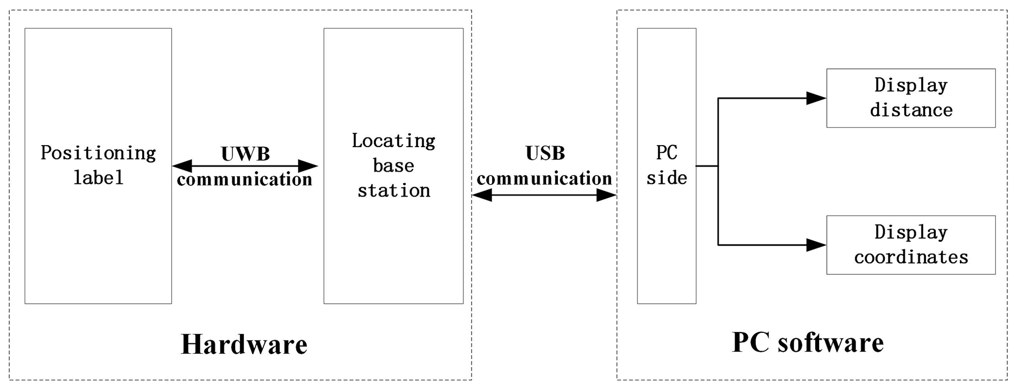
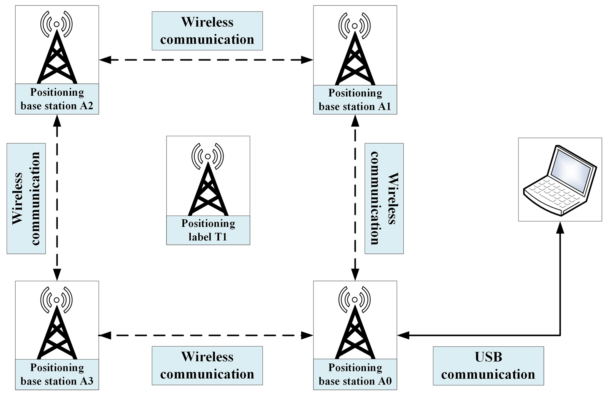
The positioning label, which is installed on the electric micro-tiller, is powered by the USB/5V interface (Wei et al., 2021a). The positioning base station is arranged at a fixed indoor location, generally divided into master and slave base stations. The main base station is connected to the PC via a USB data cable, and the rest of the slave base stations use UWB communication to transmit data to the main base station. The main base station then transmits the positioning distance data to the PC software. Focusing on the actual data collection requirements is necessary when arranging the positioning base station. However, the location of the positioning tag should always remain within the range comprising the positioning base station connections to ensure the accuracy of the positioning result (Bansal, 2021; Tian, 2019). The placement of the positioning tag at the edge or outside of the connection area of the base station will lead to poor positioning accuracy or location failure. The hardware block diagram of the positioning system is shown in Fig. 2.
2.2 Hardware design of UWB positioning system
The hardware design of the positioning system is mainly the design of the positioning module. Positioning systems generally use a two-way communication UWB. The base station and the tag must transmit and receive wireless pulse communication signals. Therefore, the hardware designs of the base station and the tag are similar and can be switched through USB and USART commands. The control module of the positioning system in this paper is an ARM-based STM32F103C8T6 microcontroller. The peripheral circuit also includes a DW1000 chip of Decawave, a power supply circuit, a LED indicator module, and USB and USART communication. The physical map of the positioning module is shown in Fig. 3.
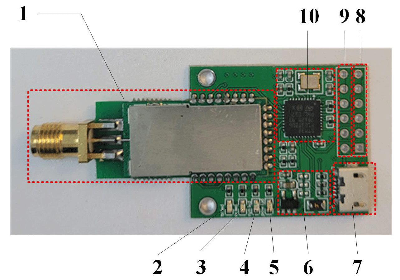
Figure 3Positioning module development board. 1 – DW1000 chip; 2, 3 – DW1000-RX LED indicator (blue); 4 – status indicator (yellow); 5 – power indicator (red); 6 – power module; 7 – USB communication interface; 8 – ST-LINK download interface; 9 – USART serial communication; 10 – MCU (microcontroller unit) chip.
Control module. As the core of the positioning system hardware platform, the STM32 main control module plays a crucial role in ensuring the stable performance of the positioning base station and tag. The STM32f103 chip uses a high-performance ARM Cortex-M3 32-bit RISC (reduced instruction set computer) core with a maximum operating frequency of 72 MHz and built-in high-speed memory. It combines high performance, real-time, digital signal processing, low power consumption, and low voltage, while maintaining high integration and ease of development. This paper uses the STM32F103C8T6 chip as the main control chip for positioning the base stations and tags, which collects and converts the signal data of the DWM1000 module into time information (Mihaldinec and Dzapo, 2020).
Communication module. The STM32 main control module communicates with the DWM1000 module through a serial peripheral interface (SPI) and transmits ranging and positioning information to the upper computer through the USB serial port.
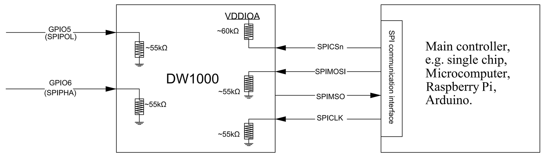
UWB signal transceiver module. This system uses the DW1000 module, whose main function is to receive or send UWB pulse signals and transmit the data to the STM32 main control module for processing through the SPI interface. The DW1000 chip is a complementary metal-oxide-semiconductor (CMOS)-based low-power wireless-transceiver-integrated circuit that follows the UWB standard in the 802.15.4-2011 protocol. The module contains an antenna, a wireless communication module, and related circuits. The module includes a 38.4 MHz onboard reference crystal oscillator. The initialization frequency error can be reduced to approximately 2 ppm (parts per million) by embedding the crystal oscillator in the product. The schematic of the module connection is shown in Fig. 4.
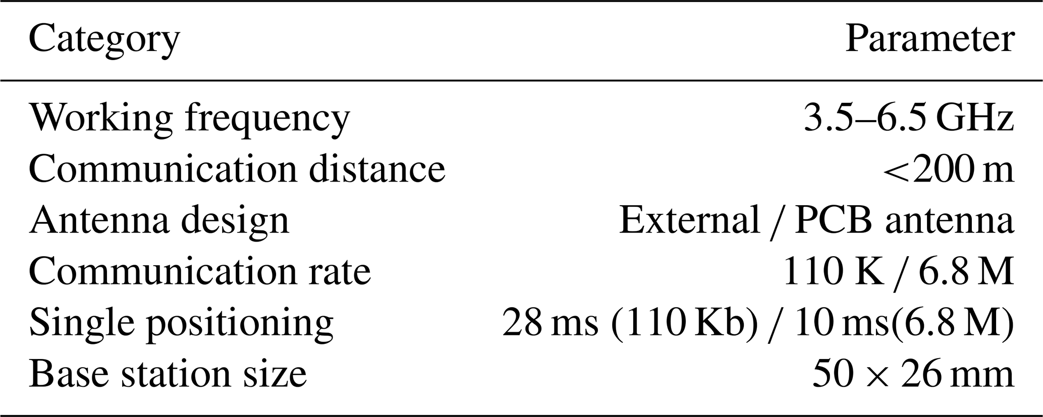
Other relevant parameters for positioning the base stations and tags are shown in Table 1.
Table 1Positioning module development board. Note: PCB – printed circuit board.
2.3 Design of UWB positioning system software
The host computer software is developed by using QT 5.7.0 MinGW, and the programming language is C. QT is a cross-platform C graphical user interface application development framework developed by Qiqu Technology in 1991.
The micro-tillage machine positioning system is designed to realize the precise positioning of remote rotary tillage in the greenhouse environment. The host computer software supports the USB communication function, which can realize the stable USB data transmission between the main positioning base station and the PC. The host computer software can display the location of the positioning tag in real-time after processing the positioning data, achieving the visualization purpose of the positioning system. On this basis, the host computer also supports background image import and inputs indoor maps into the host computer display interface. Thus, automatic positioning and remote control technologies can be effectively integrated to ensure the reliability of remote unmanned driving on the greenhouse electric micro-tiller. The most important function of the host computer is the position calculation of the positioning tag. The position calculation process is shown in Fig. 5.

3.1 UWB positioning model
UWB technology mainly uses time difference of arrival (TDOA) and two-way ranging (TWR), which are two positioning methods for the locating task, and these positioning methods have their advantages and disadvantages (Xue et al., 2021; Zhang, 2021). The following is a comparative analysis of the two methods.
3.1.1 TDOA positioning method
The time-of-arrival (TOA) method positioning accuracy is acceptable, but this positioning method requires clock synchronization between the positioning tag and base station. The TOA positioning method is less used in UWB positioning because it is difficult to achieve in reality (Mosleh et al., 2021).
The TDOA positioning method can also be called the hyperbolic positioning method, which finds the positioning coordinates by identifying the hyperbolic intersection point (Chen, 2020). The pulse signal sent by the positioning tag arrives at each positioning base station at different times. The distance between the tag and the base station is equal to the time difference multiplied by the constant speed of light c. TDOA only requires base station clock synchronization, which is easy to implement in actual situations; thus, the TDOA positioning method is often used in UWB positioning technology. The principle diagram of the TDOA positioning method is shown in Fig. 6 (Fujii et al., 2015).
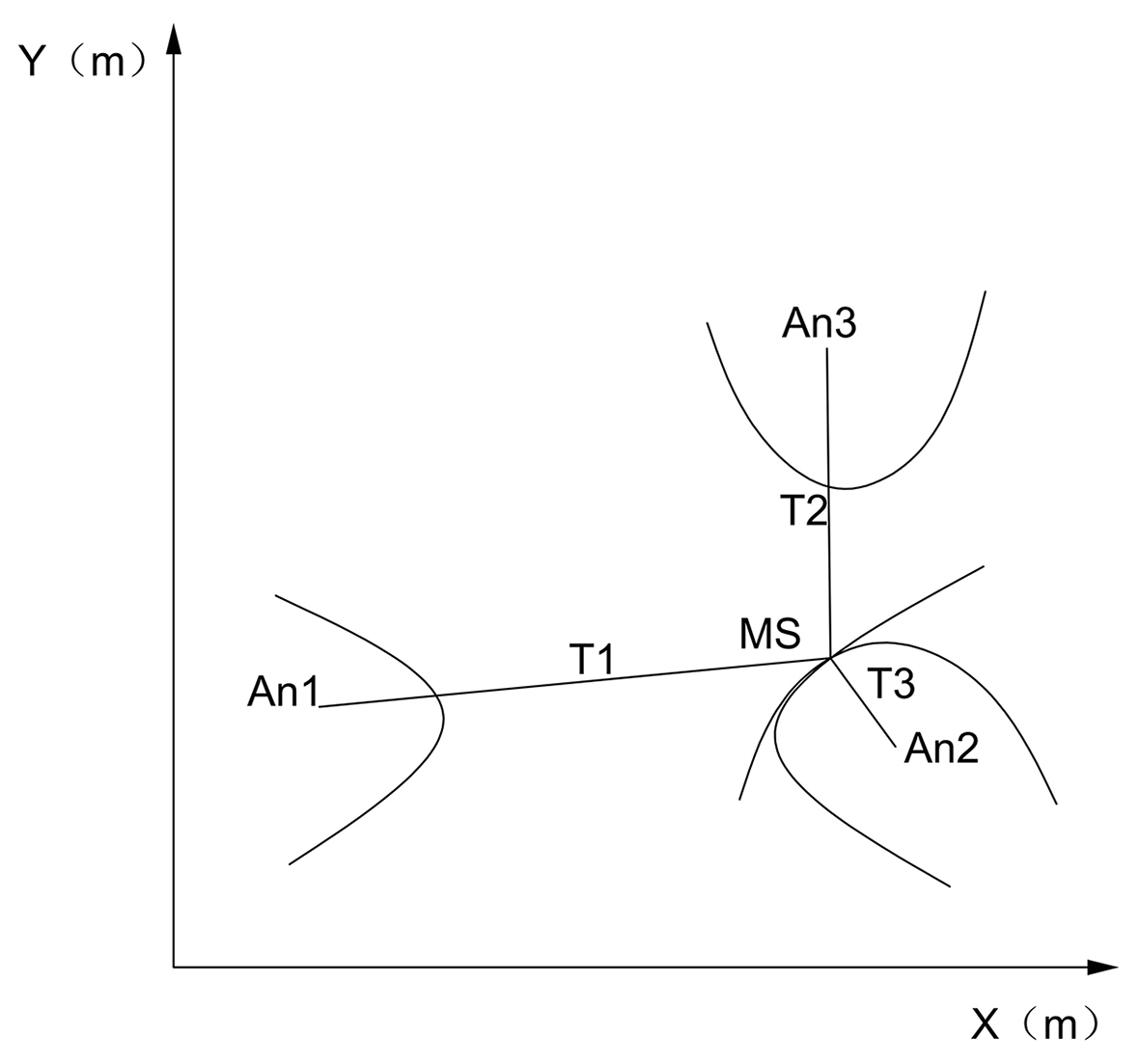
The coordinates of the positioning base stations A0, A1, and A2 and those of the positioning tag T1 are respectively assumed as (x0, y0), (x1, y1), (x2, y2), and (x,y). The time difference t10 and the distance difference d10 from the positioning tag to the base stations A0 and A1 can be obtained sequentially. The definition of the hyperbola indicates that a set of hyperbolic equations can be obtained by focusing on A0 and A1. Similarly, another set of hyperbolic equations with A0 and A2 as the focus and the distance difference d20 can be obtained. The following equations are obtained in accordance with the above analysis:
The positioning label coordinates can be solved by Eq. (1). The above solution process reveals that the TDOA positioning method does not need to consider the time synchronization of the positioning tag with the positioning base station. Clock synchronization is easily achieved in actual situations through the positioning base station. Thus, calculating the time difference between the tag and the two base stations is convenient, which is consistent with the actual positioning situation (Wei et al., 2021b).
3.1.2 TWR positioning method
The two-way ranging method (TWR) is a UWB ranging method based on TOA, which measures the distance based on the round-trip flight time of the pulse signal between the base station and the tag (Sheng, 2020). Base station A0 sends a pulse signal to tag T1 and starts timing. Tag T1 starts timing when it receives the A0 signal, and the timing ends when T1 sends a response signal to A0. Base station A0 stops timing when it receives the response signal from tag T1. The distance d from base station A0 to the positioning tag T1 can be calculated on the basis of the assumption that the total time of base station A0 is t and the time from when the tag T1 receives the signal to the time it sends the signal is t2. The principle of two-way ranging is shown in Fig. 7.

The distance calculation formula of the two-way ranging method is as follows:
where t is the total flight time of pulse signal, t1 is the timing time of base station A0, t2 is the timing time of tag T1, d is the distance from tag T1 to base station A0, and c denotes the speed of light.
The two-way ranging method does not need to consider the clock synchronization between the base station and the tag and can avoid the ranging error caused by a time drift to a certain extent to improve the ranging accuracy effectively.
3.1.3 Comparison of TDOA and TWR methods
Considering accuracy, UWB technology can achieve target carrier positioning indoors and outdoors, with an accuracy of less than 30 cm. TDOA and TWR positioning methods can achieve this accuracy.
The positioning terminal of the TDOA positioning method uses a small amount of time to send a pulse message considering the deployment of positioning base stations. Thus, a large number of positioning terminals can transmit signals within the frame rate, and the number of positioning base stations is relatively small. The positioning base station of the TWR positioning method is divided into the master and slave base stations. One master base station corresponds to four slave base stations, which is difficult to deploy.
Considering the scalability of the positioning area, the TWR positioning method requires all the slave positioning base stations in the system to communicate with the master positioning base station directly, which then limits the size of the positioning area. In comparison, the TDOA positioning method can add positioning base stations to the system without changing the system or settings. Moreover, this method has improved the scalability and is suitable for the precise positioning of greenhouses.
The TDOA positioning method, considering standby performance, only needs pulse signals to realize the positioning of the carrier tag and does not need to send and receive pulse signals multiple times continuously, thereby effectively extending the standby time. However, the TWR positioning method requires the tag to send and receive signals from the positioning base station multiple times. Base stations and tags are mostly powered by batteries. The TDOA positioning method is suitable for efficient positioning in a greenhouse environment.
For ease of use, only the location of the positioning base station must be measured, and the code assigned to the positioning base station is marked when adding a positioning base station to the positioning system based on the TDOA method. The positioning system based on the TWR positioning method must modify the positioning system algorithm on the server when adding additional positioning base stations or positioning tags. The operation process requires high technical requirements and is cumbersome.
This paper compares the two methods of TDOA and TWR, as shown in Table 2, to enable readers to understand these methods.
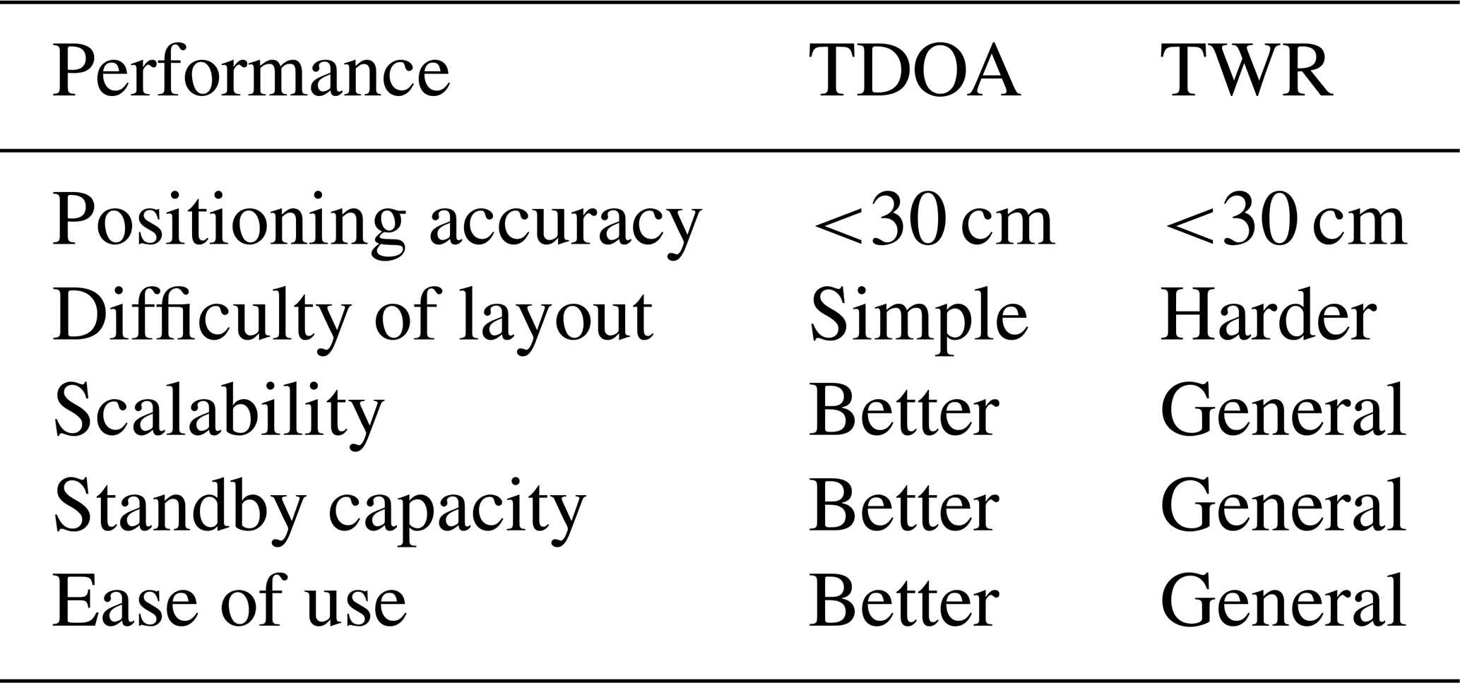
Overall, the TWR positioning method has low requirements for clock synchronization and precise positioning but consumes relatively large power and has poor scalability and ease of use. The TDOA positioning method has strong advantages considering scalability and standby performance layout efficiency. Therefore, the prototype adopts a reasonable and convenient TDOA positioning method according to the positioning requirements of the greenhouse environment.
3.2 Analysis and comparison of positioning algorithms
3.2.1 Analysis of three TDOA positioning algorithms
The above analysis reveals that the TDOA positioning method in the greenhouse has considerable advantages. The micro-tiller positioning system designed in this paper adopts the TDOA positioning method. The actual measured TDOA value is inexact in actual situations due to the influence of noise and measurement errors. Multiple solutions will be provided to the equations, and relevant positioning algorithms must be used to correct the errors. The positioning accuracy can be improved by using algorithms to produce close processed points to the real points. Commonly used positioning algorithms include those of Chan, Fang, and Taylor.
(1) Chan algorithm
The Chan algorithm is a solution method of non-recursive hyperbolic equations with analytical expression solutions. This algorithm has low complexity and can be quickly solved. Precise positioning can be achieved when the noise conforms to the Gaussian distribution. The positioning accuracy will be improved after adding base stations when using the Chan algorithm, and at least three base stations are required to participate in the work to achieve positioning (Lu et al., 2015).
Suppose the coordinates of the base stations BS1, BS2, and BS3 are, respectively, (X1, Y1), (X2, Y2), and (X3, Y3), and the coordinates of the tag are (x,y). Multiple pairs of solutions to the equations are available when the number of base stations exceeds three. The weighted least squares method is generally used in this case, and the equations are as follows:
where Ri,1 is the propagation distance difference between base station BSi and base station BS1. Xi,1 is the difference between base station BSi and base station BS1 in the x direction. Yi,1 denotes the difference between base station BSi and base station BS1 in the y direction. Ri is the distance between base station BSi and the tag. i depends on the number of base stations, and . The matrix representation is as follows:
where, in the following:
From the weighted least squares theory, the value of Z is as follows:
Q is the covariance matrix of the measurement error, and c is the speed of light. The estimated value of Z can be obtained, as shown below, when the distance between the tag and the base station is relatively long.
The result is initially solved by the long-distance algorithm when the MS (mobile station) approaches the BS, and then the distance between the tag and the base station is estimated. The estimated values of B and Ψ are determined, and Eq. (5) is used to find the Z value. If each element in Z is independent of the other, then the above calculation result can be used as the positioning result.
(2) Fang algorithm
The Fang algorithm is a solution method that can linearize the hyperbolic equations, and the solution of the linearized equation is the coordinates of the positioning tag. The algorithm is simple in principle and convenient for calculation. Only three base stations can be used for the two-dimensional positioning of the positioning tag because the Fang algorithm cannot improve the positioning accuracy by increasing the number of deployed base stations (Chen, 2017).
The expression of the distance between the base station and the tag is as follows:
Let Ri,j and ti,j be the distance and time difference between the positioning tag and the reference base stations i and j, respectively, and then the following can be obtained:
where c is the speed of light. By taking j, which is equal to 1 in Eq. (8), the following is obtained:
The coordinates of base stations BS1 and BS2 are generally set to (0, 0) and (0, X2), respectively, in the actual positioning to simplify the calculation.
Herein, the specific process in the middle is ignored. The literature is used as a reference to obtain the solution of x, and then the value of y is acquired. x and y are the coordinates of the label.
(3) Taylor algorithm
The Taylor series method is a recursive algorithm that determines the initial estimated position. The iterative value of this operation is obtained by solving the local least squares solution of the TDOA measurement error. The result of this time is used as the initial value of the next calculation, and the estimated value of the mobile station to be positioned is constantly revised, gradually approaching its real position coordinates.
Suppose the real coordinates of the label MS are (x,y), the coordinates calculated by the positioning algorithm are (x0, y0), and the two directional errors are Δx and Δy, respectively. Then, in the following:
The Taylor series is as follows:
which is expanded, as follows: (x0, y0):
where T is the remainder of Taylor expansion. Let in each recursion. The above calculation steps are repeated until is less than a set threshold, and (x0, y0) is taken before the iteration as the coordinate estimation value.
3.2.2 Simulation and comparison of three positioning algorithms
The following simulation experiments are performed on the Fang, Chan, and Taylor algorithms with MATLAB to analyse their positioning performance. The simulation environment is as follows: the coordinates of the base station are BS1(0,0), BS2(0,6000), BS3(6000,6000), and BS4(6000,0), and the coordinate unit is millimetres.
This article mainly analyses the single-point positioning of the three algorithms and simulates them in the Gaussian noise environment. The literature by Jiang (2016) indicates that the number of base stations is set to four due to the poor performance when the number of participating base stations is three. The same random measurement error is added at the randomly generated tag coordinate MS, and the TDOA measurement error is assumed to obey a Gaussian distribution with zero mean.
The simulation results are shown below. Figure 8 demonstrates the positioning performance comparison of the Chan, Taylor, and Fang algorithms at several randomly generated label coordinates under Gaussian white noise environment and when the standard deviation of TDOA is 0.05, 0.1, 0.15, 0.2, and 0.25 µs.
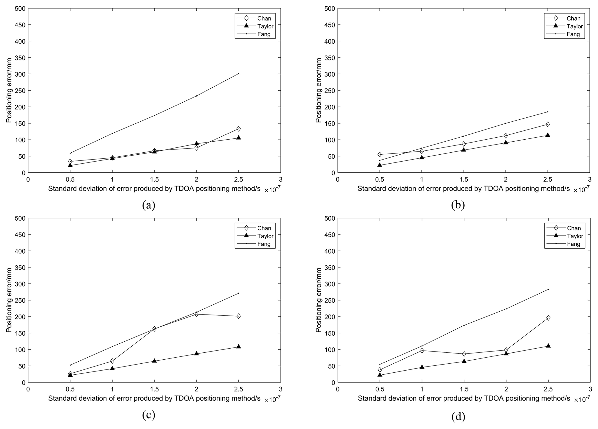
Figure 8 shows that the Taylor algorithm under the same standard deviation of the measurement error always has the smallest positioning error (that is, the best performance) when the number of base stations in a Gaussian noise environment is four. The Chan algorithm is second, followed by the Fang algorithm with the worst performance. Therefore, this paper chooses the Taylor algorithm as the reference positioning algorithm for software development.
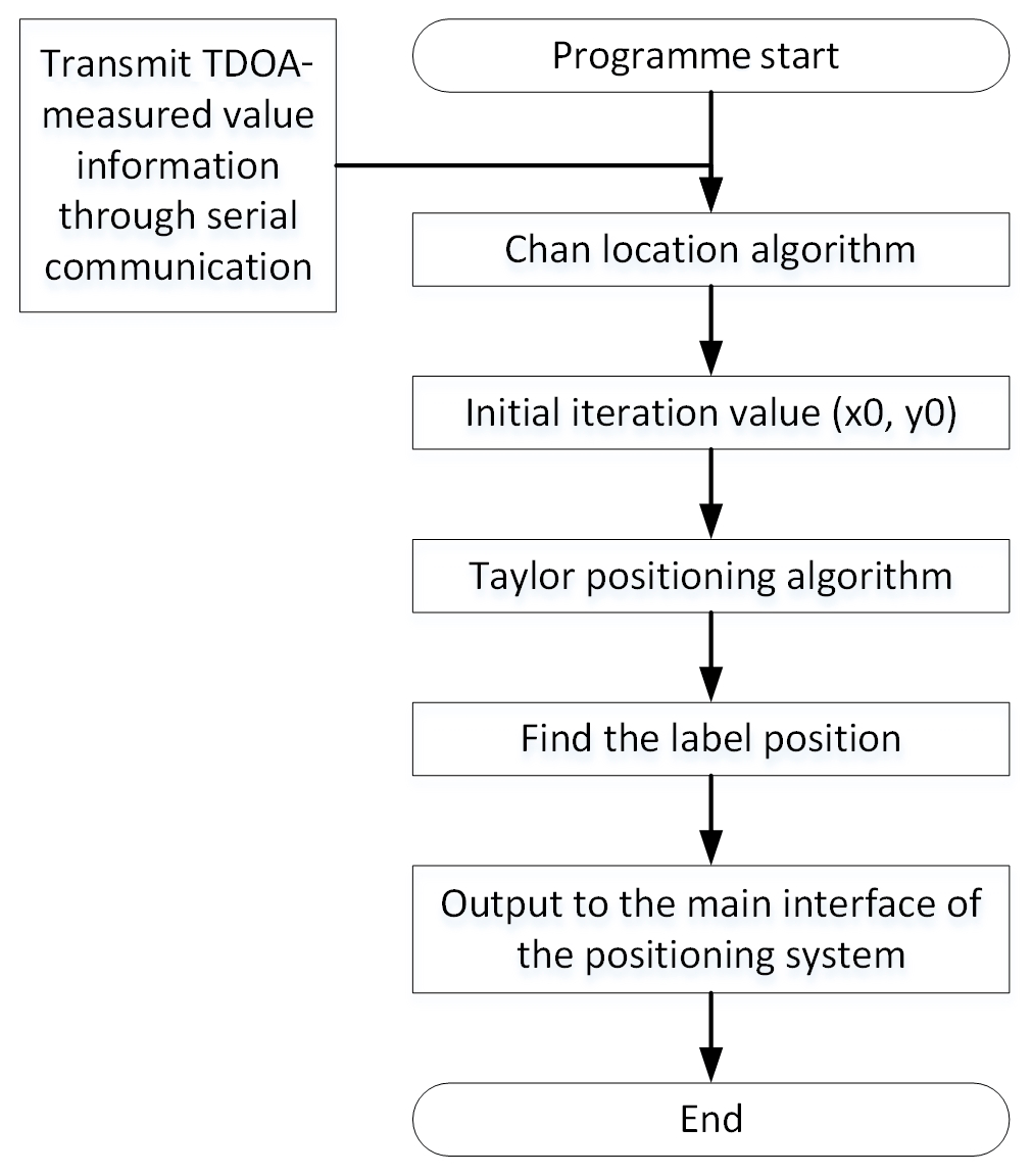
3.3 Algorithm flow
Referring to the literature by Song (2020), the Fang and Chan algorithms can meet the premise of using the Taylor algorithm to provide an initial value. The above MATLAB simulation experiment revealed that the Fang algorithm has poor positioning accuracy; thus, this paper chooses the result of the Chan algorithm to provide the iterative initial value for the Taylor algorithm (Chen et al., 2011). After obtaining the TDOA measurement value and base station coordinates, the calculation process of the upper computer software positioning algorithm in this intelligent electric micro-tiller positioning system is shown in Fig. 9.
4.1 Test conditions
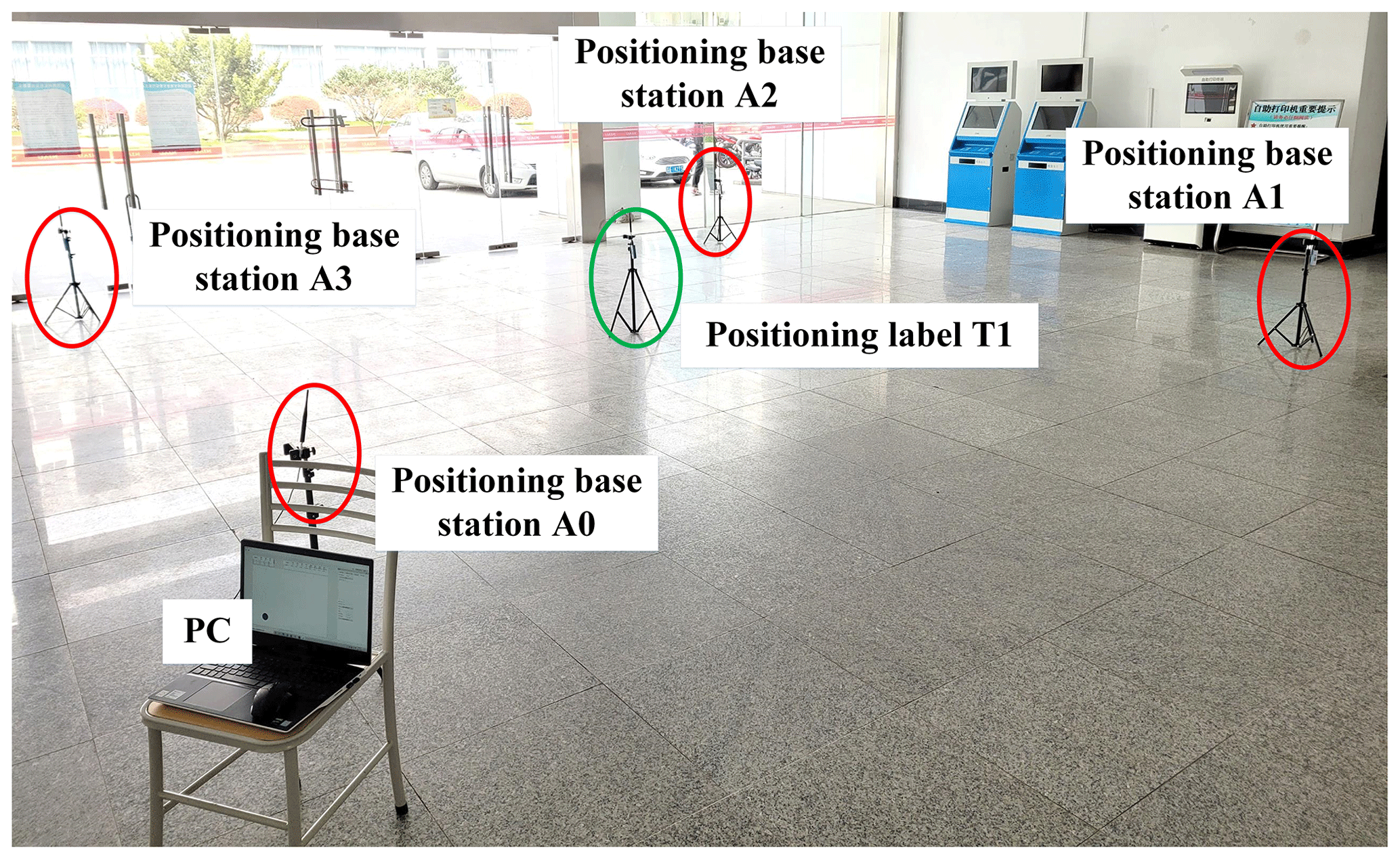
Test design and data acquisition are conducted to identify the positioning accuracy of the UWB positioning system. Using the method of fixed-coordinate experiment, the 6×6 m square flat ground, comprising multiple 60×60 cm standard floor tiles on the first floor of the Boyuan Building, Pukou Campus of Nanjing Agricultural University, is chosen as the test site, which can simulate the indoor positioning environment to a certain extent. The square field is then divided into 100 squares with a side length of 60 cm, according to the standard floor tile shape. The four positioning base stations are arranged at the four corners of the square test field, and their positions remain unchanged. The coordinates are (0,0), (0,6), (6,6), and (6,0). The positioning labels are stably arranged on the 20 optional grid vertices. The coordinate points Z1, Z2, Z3, Z4, …, Z20 taken herein are (1.2, 1.2), (1.8, 1.8), (2.4, 2.4), (3, 3), (3.6, 3.6), (4.2, 4.2), (4.8, 4.8), (1.2, 1.8), (1.2, 2.4), (1.2, 3), ( 1.2, 3.6), (1.2, 4.2), (1.2, 4.8), (2.4, 3), (2.4, 3.6), (2.4, 4.2), (2.4, 4.8), (3, 3.6), (3, 4.2), and (3,4.8), respectively, to facilitate data sorting. First, we establish the coordinate axes. Then, the upper computer collects the coordinate values on the x and y axes of the positioning label multiple times and calculates the measured average value of each coordinate. Finally, the error values of the coordinates are counted after comparing and analysing with the actual coordinates of the x and y axes, and the test scene is shown in Fig. 10. In Fig. 10, the red and green circles are the four positioning base stations and the positioning labels, respectively.
4.2 Test conditions
Figure 11 is the x-axis and y-axis coordinate values of 20 known coordinate points displayed on the host computer software using the fixed-point coordinate method. Compared with the actual coordinate value, the coordinate measurement value is slightly lower than the actual value. Comparing the measured with the actual value, the maximum positioning error does not exceed 7 cm, and the average error is 4.9 cm, which is insufficiently good.
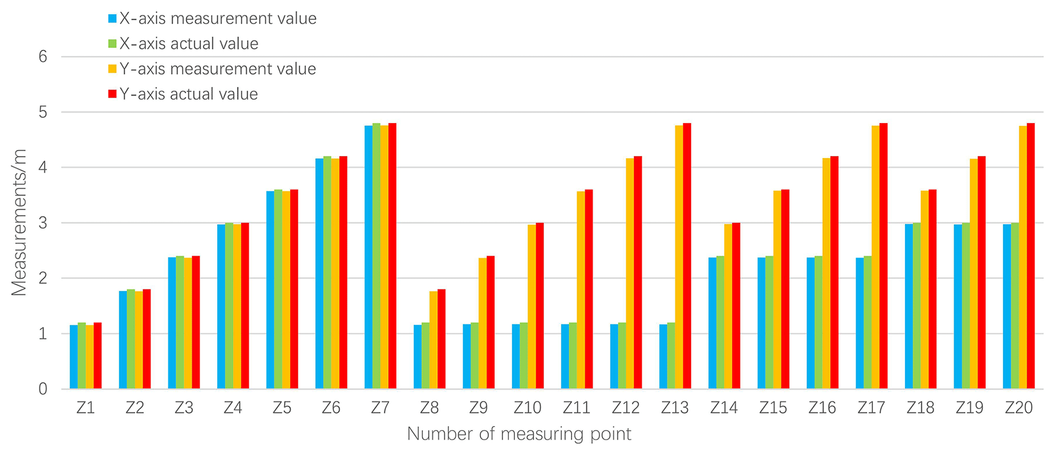
Experimental analysis revealed that the deviation between the measured value of the upper computer and the actual value is large when the positioning tag is located at the following seven coordinate points: (1.2, 1.2), (1.8, 1.8), (4.2, 4.2), (4.8, 4.8), (1.2, 1.8), (1.2, 4.2), and (1.2, 4.8). Referring to the existing literature to distinguish the signal method (Y. Chen et al., 2020; Chen et al., 2021), multiple pulse signal waves and their reflection overlapping pulse signal waves interfere with each other at this time due to the closeness of the positioning tag to the positioning base station. Thus, the positioning tag is used as a pulse signal receiver to synthesize the direct pulse and reflected signals into a complex and unstable pulse signal wave, which causes considerable fluctuation and low accuracy of the coordinate value measured by the host computer. The seven aforementioned problems of inaccurate positioning of the coordinates close to the base station are generated.
Figure 12 is a line graph of measurement error. The x-axis error, y-axis error, and coordinate deviation values in the figure generally show a fluctuating trend, and the coordinate deviation value is obtained following the formula. Therefore, the coordinate deviation value varies with the fluctuation in the x-axis and y-axis error values. Amongst these values, the coordinate deviation values at Z1 (1.2, 1.2), Z7 (4.8, 4.8), Z13 (1.2, 4.8), Z17 (2.4, 4.8), and Z20 (3, 4.8) are at a sharp point, and the coordinate deviation values near the sharp point are all larger than 0.05 m. The points near the cusp are affected by the multipath effect due to their closeness to the base station, which leads to large x-axis and y-axis errors and coordinate deviation values directly affecting the overall positioning accuracy of the positioning system (Lin et al., 2018; Wei et al., 2021c).

Therefore, this test discards the point close to the positioning base station and re-evaluates the positioning accuracy of the positioning system. The analysis shows that the maximum positioning error at this time is no more than 6 cm, and the average error is 4.4 cm, which reduces the error by 10.2 % compared with the previous one, and the positioning accuracy is high. Therefore, the location of the base stations should be emphasized when arranging positioning base stations in a greenhouse to avoid or reduce the impact of multipath effects on positioning accuracy.
-
This paper designs a positioning system suitable for greenhouse electric micro-tillers using a STM32F103C8T6 chip as the main control chip for positioning base stations and tags, based on UWB technology, to address the current frequent safety accidents of micro-tillers in greenhouses. The unmanned rotary tillage operation is realized through the cooperation of remote location visualization and wireless remote control technology. The positioning system has the advantages of stable positioning and high accuracy and has certain scientific value for the research of precise positioning technology in the existing greenhouse.
-
This paper comprehensively analyses two widely used wireless positioning methods, namely TDOA and TWR, by examining and selecting the suitable TDOA positioning method for the greenhouse environment from five aspects, i.e. positioning accuracy, layout difficulty, scalability, standby capability, and ease of use. The optimization effects of the Fang, Chan, and Taylor positioning algorithms are simultaneously compared under the same standard deviation of the measurement error, and MATLAB is used for the simulation. Finally, the Taylor algorithm demonstrated the best performance. The reasonable choice of the positioning method and algorithm directly affects the positioning accuracy.
-
The accuracy test results of the positioning system show that the maximum positioning error does not exceed 6 cm, and the average error is 4.4 cm. This finding indicates the high positioning accuracy of the greenhouse electric micro-tiller positioning system designed in this paper based on UWB technology, the TDOA method, and the Taylor algorithm. The positioning accuracy is improved after discarding the data points close to the base station, and the positioning error is reduced by 10.2 %. Thus, attention should be provided to the placement of base stations when locating base stations in a greenhouse to avoid or reduce the impact of multipath effects on positioning accuracy.
All the data used in this paper can be obtained on request from the corresponding author.
YL, QC, and MX finished the positioning technology and software and hardware designs. HZ and GW studied the function realization of the micro-tiller positioning system. WZ and HW did the precision test. YM helped with the revision of the paper.
The contact author has declared that neither they nor their co-authors have any competing interests.
Publisher's note: Copernicus Publications remains neutral with regard to jurisdictional claims in published maps and institutional affiliations.
The authors thank the reviewers, for their valuable comments, and Copernicus Publications, for their language and typesetting services.
This research has been supported by the Jiangsu Provincial Key Research and Development Programme (grant no. NJ2020-35) and Research and Innovation Training Project of Nanjing Agricultural University (grant no. 202110307004P).
This paper was edited by Peng Yan and reviewed by three anonymous referees.
Arunjith, K. S., Ghivela, G. C., and Sengupta, J.: Design and analysis of novel tri-band band pass filter for GSM, WiMax and UWB Applications, Kluw. Commun., 118, 3457–3467, https://doi.org/10.1007/s11277-021-08188-7, 2021.
Bansal, B.: New UTD based time-domain solution for UWB diffraction in 3-D environments, Kluw. Commun., 118, 2365–2382, https://doi.org/10.1007/s11277-021-08130-x, 2021.
Chen, S.: TDOA indoor positioning technology based on Fang algorithm, Journal of Terahertz Science and Electronic Information, 15, 752–755, https://doi.org/10.11805/TKYDA201705.0752, 2017 (in Chinese).
Chen, X.: Research on the positioning system of nursing robot based on UWB, MS thesis, Hebei University of Science and Technology, China, 83 pp., https://doi.org/10.27107/d.cnki.ghbku.2020.000027, 2020 (in Chinese).
Chen, D., Tang, H., and Wu, J.: Research on TDOA co-location algorithm based on Chan and Taylor, Computer Science, 38, 406–407, https://www.jsjkx.com/CN/Y2011/V38/IZ10/406 (last access: 28 February 2022) (in Chinese) 2011.
Chen, Q., Zhao, Y. C., Yin, J. B., and Ma, Y. B.: Automated mechanical transmission technology and development trend, Appl. Mech. Mater., 3675, 280–284, https://doi.org/10.4028/www.scientific.net/AMM.697.280, 2015.
Chen, Y., Avitabile, P., and Dodson, J.: Data consistency assessment function (DCAF), Mech. Syst. Signal Pr., 141, 106688, https://doi.org/10.1016/j.ymssp.2020.106688, 2020.
Chen, Y., Avitabile, P., Page, C., and Dodson, J.: A polynomial based dynamic expansion and data consistency assessment and modification for cylindrical shell structures, Mech. Syst. Signal Pr., 154, 107574, https://doi.org/10.1016/j.ymssp.2020.107574, 2021.
Ding, Y., Zhan, P., Zhou, Y., Yang, J., Zhang, W., and Zhu, K.: Design and experiment of motion controller of Beidou positioning field information acquisition platform, Transactions of the Chinese Society of Agricultural Engineering, 33, 178–185, https://doi.org/10.11975/j.issn.1002-6819.2017.12.023, 2017 (in Chinese).
Du, Z., Chen, Y., Zhang, J., Han, X., Geng, A., and Zhang, Z.: Development status and prospect of rotary tillage machinery at home and abroad, Journal of Chinese Agricultural Mechanization, 40, 43–47, https://doi.org/10.13733/j.jcam.issn.2095-5553.2019.04.08, 2019 (in Chinese).
Emadian, S. R., Ahmadi-Shokouh, J., Ghobadi, C., and Nourinia, J.: Study on frequency and impulse response of novel triple band notched UWB antenna in indoor environments, AEU-Int. J. Electron. C., 96, 93–106, https://doi.org/10.1016/j.aeue.2018.09.003, 2018.
Fujii, K., Sakamoto, Y., Wang, W., Arie, H., Schmitz, A., and Sugano, S.: Hyperbolic positioning with antenna arrays and multi-channel pseudolite for indoor localization, Sensors, 15, 25157–25175, https://doi.org/10.3390/s151025157, 2015.
Guo, L.: Research on UWB-based positioning technology in indoor complex environment, MS thesis, Huaqiao University, China, 89 pp., https://doi.org/10.27155/d.cnki.ghqiu.2020.000393, 2020 (in Chinese).
Guo, N., Hu, J., and Wang, H.: Operation control system of rice transplanter based on GPS navigation, Transactions of the Chinese society for agricultural machinery, 44, 200–204, https://doi.org/10.6041/j.issn.1000-1298.2013.01.038, 2013 (in Chinese).
Jiang, K.: Research on location algorithm based on TDOA in cellular network, MS thesis, Nanjing University of Posts and Telecommunications, China, 67 pp., 2016 (in Chinese).
Li, M., Imou, K., Liu, Z., Wu, W., Li, Z., and Wu, B.: The positioning algorithm of the omnidirectional visual positioning system for agricultural machinery, Transactions of the Chinese Society of Agricultural Engineering, 29, 52–59, http://www.tcsae.org/nygcxb/article/abstract/20130208 (last access: 16 March 2022), 2013 (in Chinese).
Lin, X., Wang, X., Lin, Cai., Geng, J., Xue, J., and Zheng, E.: Collection and optimization of positioning information for greenhouse agricultural vehicles based on ultra-wideband, Transactions of the Chinese Society for Agricultural Machinery, 49, 23–29, https://doi.org/10.6041/j.issn.1000-1298.2018.10.003, 2018 (in Chinese).
Liu, J., Qiao, B., Chen, Y., Zhu, Y., He, W., and Chen, X.: Impact force reconstruction and localization using nonconvex overlapping group sparsity, Mech. Syst. Signal Pr., 162, 107983, https://doi.org/10.1016/j.ymssp.2021.107983, 2022.
Lu, Y., Wang, B., and Qiu, J.: Research on positioning of CHAN algorithm in LOS and NLOS environment, Computer Technology and Development, 25, 61–65, https://d.wanfangdata.com.cn/periodical/wjfz201509013 (last access: 28 February 2022), 2015 (in Chinese).
Luo, X., Zhang, Z., Zhao, Z., Chen, B., Hu, L., and Wu, X.: DGPS automatic navigation control system of Dongfanghong X-804 tractor, Transactions of the Chinese Society of Agricultural Engineering, 44, 139–145, https://doi.org/10.3969/j.issn.1002-6819.2009.11.025, 2009 (in Chinese).
Mihaldinec, H. and Dzapo, H.: Method for joint flexion angle estimation using UWB ranging with clock model compensation, Automatika, 61, 132–140, https://doi.org/10.1080/00051144.2019.1690290, 2020.
Mosleh, M. F., Zaiter, M. J., and Hashim, A. H.: Position estimation using trilateration based on TOA/RSS and AOA measurement, J. Phys. Conf. Ser., 1773, 012002, https://doi.org/10.1088/1742-6596/1773/1/012002, 2021.
Sheng, K.: Research on indoor UWB network positioning method, MS thesis, Beijing University of Civil Engineering and Architecture, China, 58 pp., https://10.26943/d.cnki.gbjzc.2020.000584, 2020 (in Chinese).
Song, X.: Research on positioning of CHAN algorithm in LOS and NLOS environment, MS thesis, College of Automation Engineering, Northeast Electric Power University, China, 72 pp., https://10.27008/d.cnki.gdbdc.2020.000099, 2020 (in Chinese).
Tian, Y.: Research on indoor wireless positioning technology based on UWB, MS thesis, Jilin University, China, 70 pp., 2019 (in Chinese).
Wei, W., Cong, R., Xue, T., Abraham, A. D., and Yang, C.: Surface roughness and chip morphology of wood-plastic composites manufactured via high-speed milling, Bioresources, 16, 5733–5745, https://doi.org/10.15376/biores.16.3.5733-5745, 2021a.
Wei, W., Li, Y., Xu, Y., and Yang, C.: Research on tool wear factors for milling wood-plastic composites based on response surface methodology, Bioresources, 16, 151–162, https://doi.org/10.15376/biores.16.1.151-162, 2021b.
Wei, W., Shen, J., Yu, H., Chen, B., and Wei. Y.: Optimization design of the lower rocker arm of a vertical roller mill based on ANSYS workbench, Appl. Sci., 11, 10408–10422, https://doi.org/10.3390/app112110408, 2021c.
Xue, B., Li, Z., Lei, P., Wang, Y., and Zou, X.: Wicsync: a wireless multi-node clock synchronization solution based on optimized UWB two-way clock synchronization protocol, Measurement, 183, 109760, https://doi.org/10.1016/j.measurement.2021.109760, 2021.
Yao, Z., Cao, X., Dong, L., Chen, L., Zeng, S., and Zou, X.: Design and test of remote control tiller, Journal of Agricultural Mechanization Research, 42, 52–56, https://doi.org/10.13427/j.cnki.njyi.2020.06.009, 2020 (in Chinese).
Zeng, M., Tan, B., Ding, F., Zhang, B., Zhou, H., and Chen, Y.: An experimental investigation of resonance sources and vibration transmission for a pure electric bus, P. I. Mech. Eng. D-J. Aut., 234, 950–962, https://doi.org/10.1177/0954407019879258, 2020.
Zhang, J., Zhang, B., Zhang, N., Wang, C., and Chen, Y.: A novel reliable robust adaptive event-triggered automatic steering control approach of autonomous land vehicles under communication delay, Int. J. Robust. Nonlin., 31, 1–29, https://doi.org/10.1002/rnc.5393, 2021.
Zhang, T.: Electronic fence device based on UWB positioning technology, J. Phys. Conf. Ser., 1802, 042014, https://doi.org/10.1088/1742-6596/1802/4/042014, 2021.
Zhao, Q., Zhang, Y., Lu, Y., Zhang, B., Pei, J., Zhang, Z., and Du, C.: Correlation analysis of operation accidents of micro-tillers and design defects of machine tools, Journal of Agricultural Mechanization Research, 38, 255–262, https://doi.org/10.13427/j.cnki.njyi.2016.07.052, 2016 (in Chinese).
- Abstract
- Introduction
- Positioning technology and software and hardware designs of a greenhouse electric micro-tiller
- Function realization of micro-tiller positioning system
- Precision test of UWB positioning system for greenhouse electric micro-tiller
- Conclusions
- Code and data availability
- Author contributions
- Competing interests
- Disclaimer
- Acknowledgements
- Financial support
- Review statement
- References