the Creative Commons Attribution 4.0 License.
the Creative Commons Attribution 4.0 License.
 | 16 Dec 2022
Tooth profile design of a novel helical gear mechanism with improved geometry for a parallel shaft transmission
Enyi He
Shihao Yin
Based on the space curve meshing equation, a novel helical gear mechanism with improved geometry is presented. First, equations of the theoretical contact curves were derived based on the space curve meshing theory. Then, tooth surfaces with a concave–convex meshing form were constructed, depending on the contact curves. The tooth profiles were improved as the theoretical contact curves were corrected by predestining the designed transmission errors. The effect of the center distance error on the transmission errors was studied, and the effects of gear modifications on transmission errors and maximum contact stresses were also investigated. The results show that the transmission error curves of the improved gear drive become much smoother. Maximum contact stresses of the improved gear drive are decreased synchronously.
- Article
(3558 KB) - Full-text XML
- BibTeX
- EndNote


A line gear (Chen, 2014), which is also named space curve meshing wheels in the published papers (Chen et al., 2007), is applicable to micro-mechanical systems due to its small size, light weight and large transmission ratio. Line gear pairs can be applied to transmissions with perpendicular shafts (Chen et al., 2009), intersecting shafts (Zhen et al., 2013) or skew shafts (Chen et al., 2013). Based on the line gear theory, non-generated double circular arc helical gear drives and pure rolling cylindrical helical gear drives have been proposed (Long et al., 2022; Zhen et al., 2020b). Different kinds of gear profiles can be constructed based on the line gear theory.
There are many studies detailing the geometry-improved methods of different gears with the aim to improve transmission performance. Since the beveloid gear has been proposed (Beam, 1954), concave and convex modification analysis for skewed beveloid gears considering misalignment has been studied (Siyuan et al., 2019). The meshing theory and the simulation of non-involute beveloid gears has been studied (Li et al., 2004). Besides, Liu et al. (2018) have discussed effects of tooth modifications on the mesh characteristics of a crossed beveloid gear pair with a small shaft angle. Litvin (1992) derived that the transmission error (TE) is the main source of vibration and noise. Lots of research on gear modification has been studied. Litvin et al. (2003, 2006) found that predestining a parabolic type of TE means that it is able to absorb most of the linear function of TEs caused by misalignment, and predestining the TE has proved to be a method to improve the transmission precision and to reduce noise. Ni et al. (2017) have studied the transmission performance of a crossed beveloid gear transmission with a parabolic modification. Fuentes et al. (2010) have investigated the computerized design method of conical involute gears to improve the bearing contact and reduce noise. A simulation of the meshing and contact of hyperbolical-type normal circular-arc gears has also been studied (Chen et al., 2016).
The aforementioned research covers numerous efforts in improving the transmission performance of different gears through profile modification. The geometric design, meshing simulation and stress analysis of pure rolling cylindrical helical gear drives and pure rolling rack and pinion mechanisms are studied (Chen et al., 2020a, b).
Based on the line gear theory, a novel helical gear mechanism (NHGM) with a concave–convex meshing form is presented for parallel shaft transmission. The geometry modification of the NHGM is researched to improve the transmission precision. The effect of the center distance error on the TEs is analyzed. The effect of the geometry modification on the maximum contact stresses are studied. The principle is expounded through theoretical research, and the feasibility is verified by a numerical method.
2.1 Tooth surfaces design of NHGM
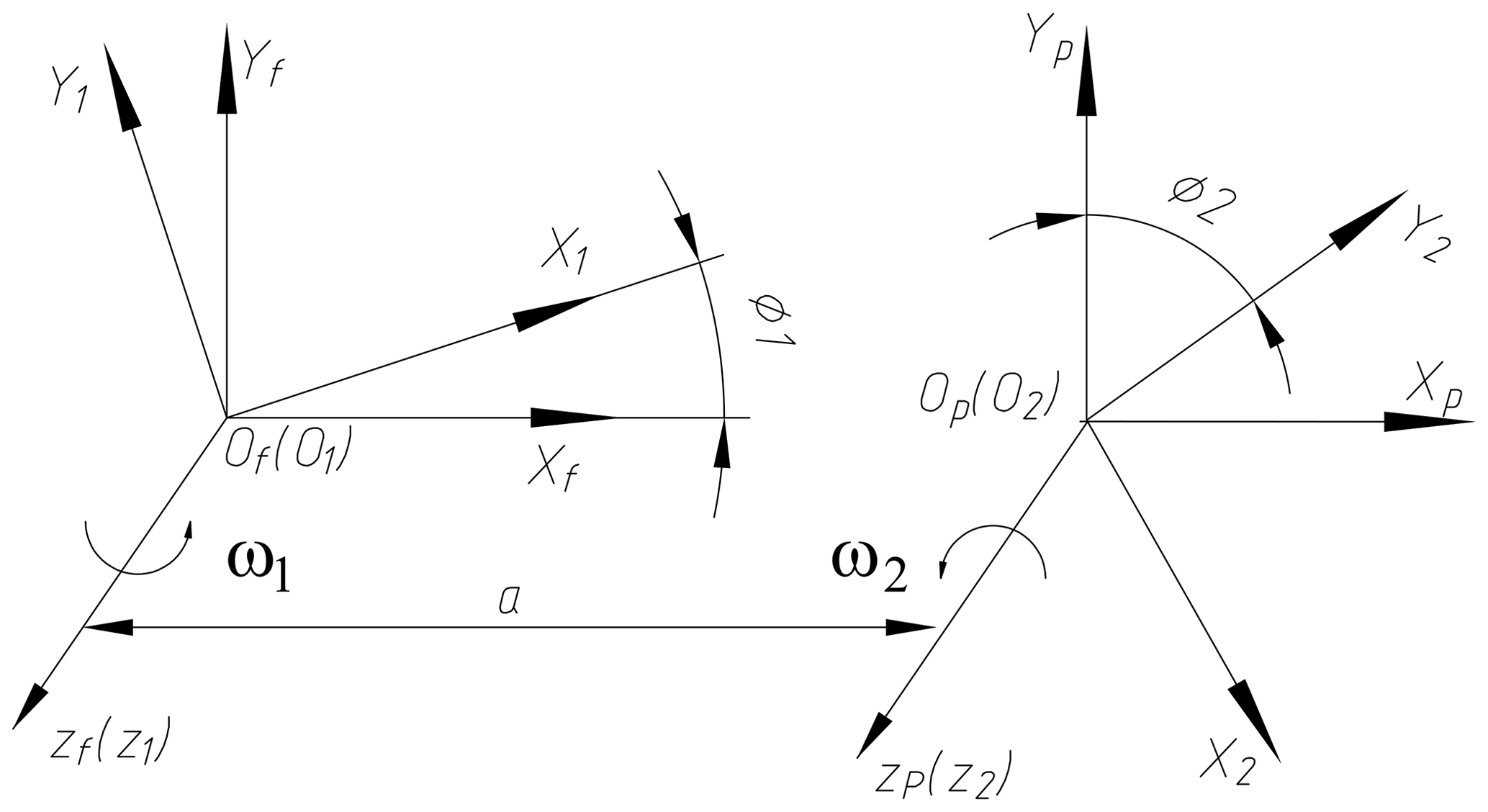
As shown in Fig. 1, coordinate systems S1 and S2 are connected to driving gear and driven gear, and coordinate systems Sf and Sp are fixed with the frame. In initial engagement position, S1 and S2 coincide with Sf and Sp, respectively. φ1 and φ2 are the rotation angles of the driving and driven gear, respectively.

Space curve L1 and L2 exist on the surfaces of the driving gear and driven gear. As shown in Fig. 2, the contact form of the tooth surfaces is concave–convex. R1 is the section radius of surface Ω1, and R2 is the section radius of surface Ω2. M1 is a contact point that exists on the forward contact curve, and M2 is a contact point that exists on the reverse contact curve. To avoid interference, the induced normal curvature K12 should be less than 0, which is shown as Eq. (1) (Litvin, 1992).
The surface equations of Ω1 and Ω2 are expressed as Eqs. (2) and (3) if contact curves pass through point M1. And they can be expressed as Eqs. (4) and (5) when contact curves pass through point M2. In this paper, Eqs. (2) and (3) are taken as an example for the follow-up study.
where x1, y1 and z1 are components of the contact curve equations of the driving gear which are expressed as Eq. (7). x2, y2 and z2 are components of the contact curve equations of the driven gear which are expressed as Eq. (8). xr1 and yr1 are components of the section equations of the driving gear, and xr2 and yr2 are components of the section equations of the driven gear. The section equations of the tooth surfaces which contain the parameters xr1, yr1, xr2 and yr2 are expressed as Eq. (6).
Here, R is the radius of the circular section, and μ is the rectangular coordinate parameter of the circular section.
Contact curve equations of the driving gear surface are expressed as Eq. (7), and contact curve equations of the driven gear surface can be obtained according to Eq. (8).
Here, m is the helix radius, n is the pitch parameter of contact curve, and t is the variable parameter of the contact curve L1.
Here, M21 is the transformation matrix, and it is expressed as Eq. (9).
Here, a is the center distance.
According to the above formulas, the tooth surfaces equation of the driving and driven gears can be obtained, and then the induced normal curvature K12 can be deduced (Litvin, 1992). We find that, when , there is no interference.
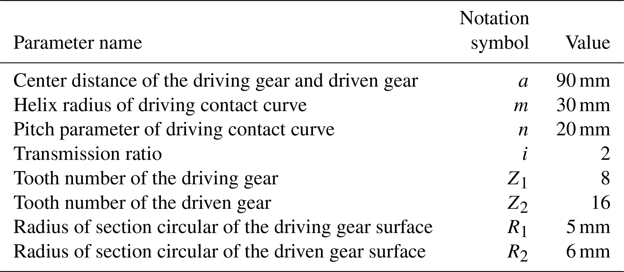
According to the above formulas, a pair of NHGMs is designed. The parameters are listed in Table 1. The 3D models of the NHGM were established according to Eqs. (10) and (11).
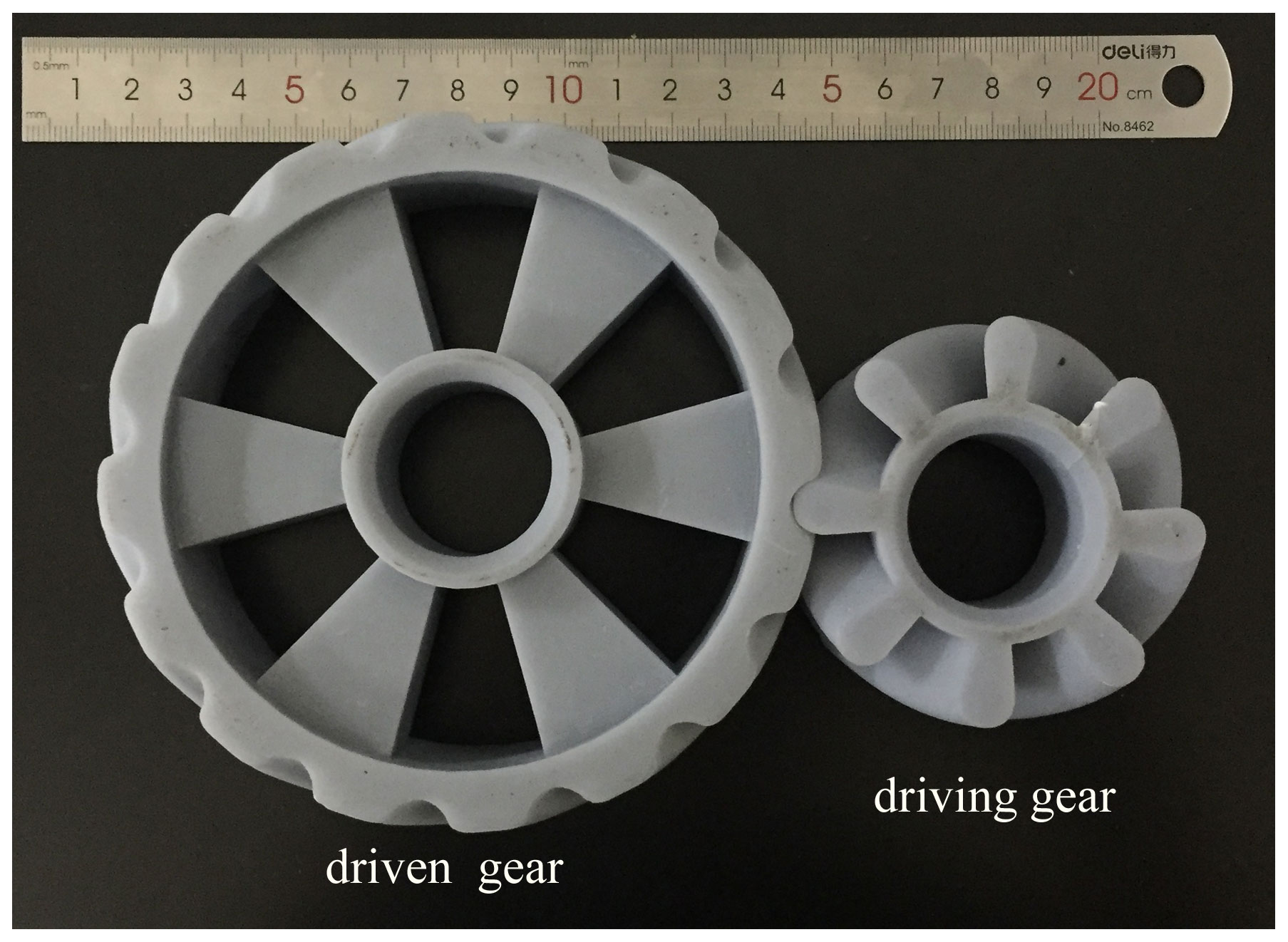
As shown in Fig. 3, they were manufactured with a 3D printer. The 3D printer model is Lite450HD. The resolution is 0.001 mm. The material is a gray high-temperature, photosensitive resin (YGH-5001).
2.2 Tooth surfaces of the NHGM with improved geometry
The tooth contact analysis (TCA) is the main method to obtain TEs. The equation of TCA is expressed as Eq. (12) (Litvin, 1992).
Here, Ω is the surface equation, and n is the normal vector of the corresponding surface. It is expressed as Eq. (13).
For NHGM, the parameters of the meshing surfaces must comply with Eq. (14), which was obtained from a space curve meshing equation (Chen, 2014).
When φ1 is provided, the functions ϕ2(ϕ1,δa) and μ2(ϕ1,δa) can be solved according to Eq. (12). Then, the TEs can be expressed as Eq. (15).
Here, δa is the center distance error.
TEs can be changed by applying preset transmission errors (PTEs; Litvin, 1992). After presetting the transmission errors, the rotation angle of the driven gear is expressed as Eq. (16). The improved surface equation of the driven gear is expressed as Eq. (17).
Here, , and are parameters of the improved contact curve of the driven gear. They can be obtained in the same way for obtaining x2, y2 and z2; one just needs to place φ2PTE instead of φ2 in the formula.
2.3 Calculation method of maximum contact stress of NHGM
While the tooth surface equations are obtained, the maximum contact stress of a loaded gear drive could also be obtained by the application of the Hertz contact theory.Shown in Fig. 2, force of the gear drive can be represented with Eq. (18).
Here, Fn is the force which is acting on the gear tooth surface, l is the arm of the force, T is the torsion load, rr is the unit vector of Fr, and cos(rr,n) is the cosine value of the angle between vector rr and n.
Based on the Hertz contact theory, the maximum contact stress can be obtained by putting Eq. (18) into Eq. (19).
la and lb are the long half-axis and short half-axis of the contact ellipse, respectively. They are expressed as Eq. (20).
and k22 are the principal curvatures of the gear surfaces. They can be obtained by solving Eq. (21). E and v are the modulus of elasticity and Poisson's ratio of the gear surfaces, respectively. α and β are the integral coefficients of the contact ellipse, and they can be obtained by solving Eq. (22) (Brewe and Hamrock, 1997; Hamrock and Brewe, 1983).
The following conditions of the gear drives were considered, and then the NHGMs were designed. Then, kinematic analysis was carried out with no center distance error (δa=0).
TCA was applied to obtain TEs which were caused by center distance error (δa≠0). TEs of the NHGMs, with improved and unimproved geometry, respectively, were studied. The maximum contact stress of the NHGM was also studied.
- (i)
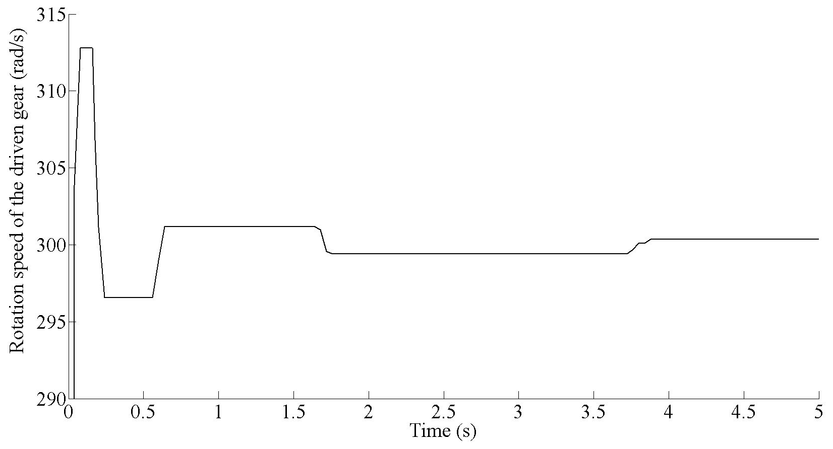
Case 1: transmission ratio of the NHGM with δa=0 was considered. Based on the tooth surface construction method mentioned above, a NHGM, with the parameters shown in Table 1, was established. Then the kinematic experiment was carried out. We set the rotation speed of the driving gear at 600 (rad s−1). It can be seen from Fig. 4 that the speed of the driven gear quickly increased from 0 to 310 rad s−1 at the beginning of the transmission, rapidly stabilized at around 300 rad s−1 and fluctuated here. We set the material to be 45# steel in the meshing process and set the solid contact of the tooth surface. Elastic deformation will occur in the transmission process of the gear, resulting in a slight fluctuation in the driven gear speed at about 300 rad s−1. As the rotation speed of the driven gear is 300 rad s−1, and the rotation speed of the driving gear is 600 rad s−1, this means that the transmission ratio is almost equal to 2. Thus, we can conclude that the designed gear pair can meet the expected transmission ratio.
- (ii)
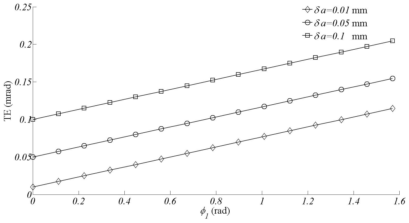
Case 2: TEs of the improved and unimproved NHGM. As shown in Fig. 5, TEs of the unimproved gear drive rise linearly from the minimal value to the maximum value. They are proportional to the value of the center distance error.
In order to make the TEs controllable, an improved NHGM with preset transmission errors is designed. Considering that trigonometric functions have stable oscillation characteristics, PTEs were designed as a trigonometric function. The function of the PTEs is expressed as Eq. (23), and the amplitude of the function can be adjusted according to the magnitude of the transmission errors. In this case, the amplitude is 0.1.
By putting Eq. (23) into Eqs. (16) and (17), equations of the improved driven tooth surface were obtained. TEs of the improved NHGM were studied. As shown in Fig. 6, TEs of the improved gear drive become much smoother. While the center distance error becomes larger, transmission errors also become larger, but they still maintain periodic changes. This phenomenon is beneficial to the stability of transmission.
- (iii)
Case 3: maximum contact stress of the improved and unimproved NHGM. A theoretical calculation is performed to study the maximum contact stress of the NHGM with improved and unimproved geometry. The main geometry parameters for the gear drive are shown in Table 1. The torque of the gear drive was set at 7.5 Nm, and then the force of the tooth surface was obtained according to Eq. (18). The material of the gear drive was set as steel, with MPa and v=0.3. Equations of the tooth surfaces were obtained from Eqs. (10) and (11). By putting Eqs. (10) and (11) and the parameters mentioned above into Eqs. (19), (20), (21) and (22), the maximum contact stresses of the gear drive were obtained, and they are shown as Fig. 7.

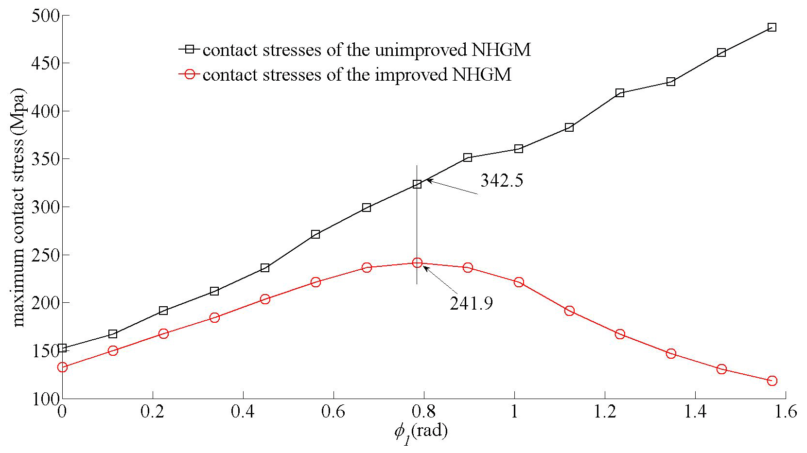
As shown in Fig. 7, the maximum contact stress of the unimproved NHGM shows a linear change, while the maximum contact stress of the improved NHGM shows a nonlinear change. When φ1=0.25π, the maximum contact stress reaches the maximum value. Under the same bearing conditions, the maximum contact stress of the improved NHGM changes more smoothly, which means it has a stronger bearing capacity. The reason for this result is that the parameters of the contact ellipses are changed (see Fig. 9). The contact ellipses can be calculated, and they are shown in Fig. 10.
The maximum contact stresses of meshing gears can be calculated by the finite element method. For this case, maximum contact stresses that can be calculated by the finite element method are shown as Fig. 8, where φ1=0.25π.
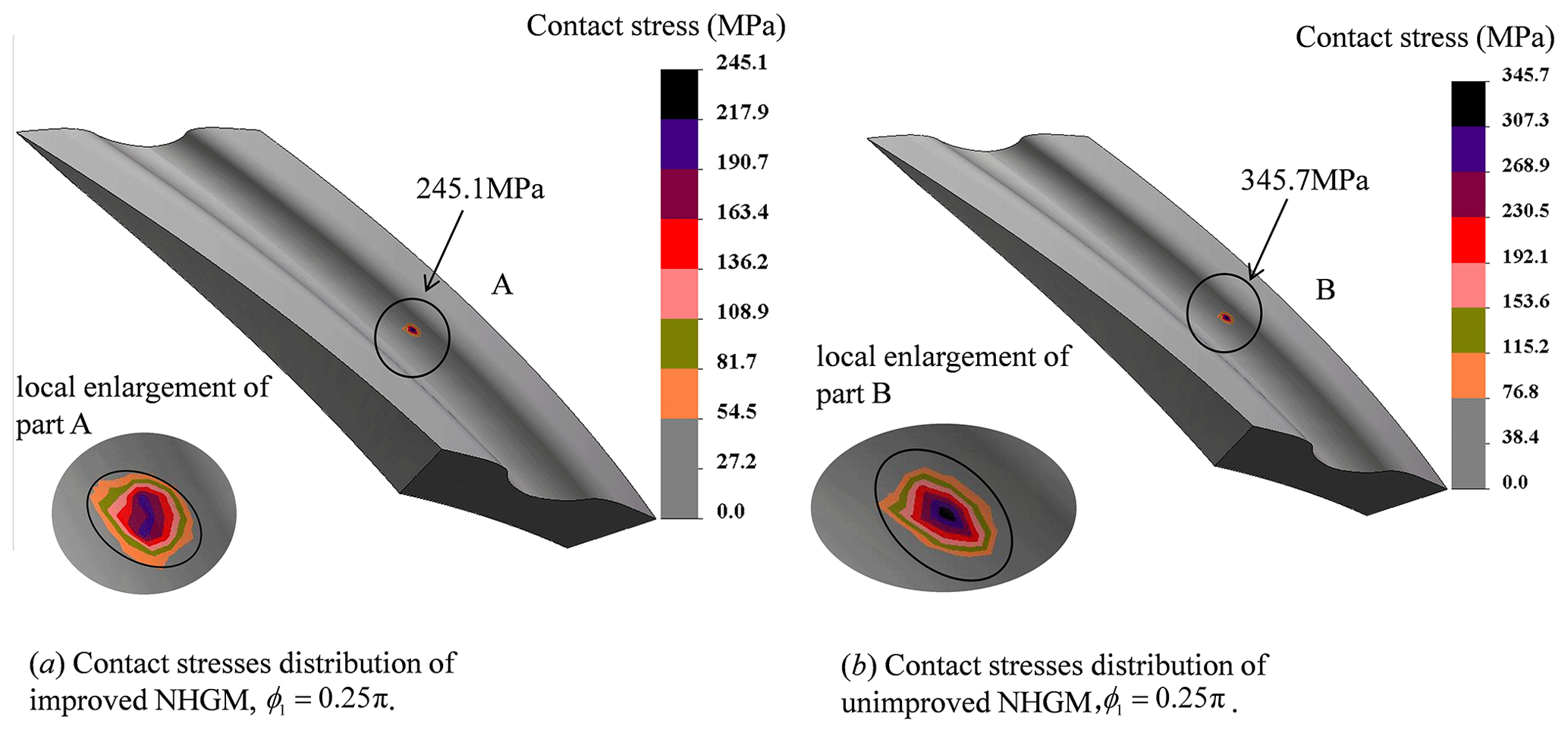
Compared with the results obtained by the finite element method shown in Fig. 8, the relative error in the maximum contact stress which is obtained by the theoretical calculation method shown in Fig. 7 is 1.32 % and 0.93 %, respectively.
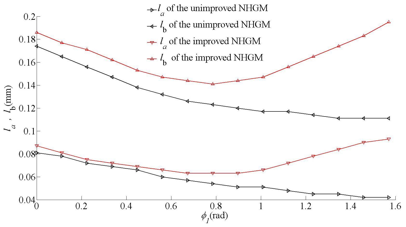
As shown in Fig. 9, the values of the long and short axes of the contact ellipse of the unimproved gear drive decrease linearly. The values of the long and short axes of the contact ellipse of the improved gear drive are larger than the unimproved one, and they are not linearly changed. For the improved gear drive, the values of the long and short axes reach the minimum, where φ1=0.25π. The contact ellipse of the improved and unimproved gear drive is shown in Fig. 10, while φ1 increases from 0 to 0.5π with a spacing of .

The size of the contact ellipse of the improved NHGM decreases first and then increases. While φ1=0.25π, it reaches the minimum. The size of the contact ellipse of the unimproved NHGMs is smaller than those of the improved ones, and they are decreasing all the way.
Based on the above analysis, we can conclude that the improved NHGM has a stable transmission performance and stronger bearing capacity than the unimproved one.
For line gears, the driving and driven tines can both be regarded as cantilever beams which cannot absorb enough loading for conventional mechanical applications. Thus, line gears are suitable for micro-mechanical systems with low power. A novel pure rolling circular arc helical gear mechanism (CAHGM) with concave–convex meshing is presented for parallel transmission applications (Zhen et al.,2020). Due to the concave–convex contact form, it is able to carry more loads than the line gear. However, assembly errors have not be considered in constructing the gear surface. Litvin (2006) used the rack cutter with a parabolic profile to generate the profile-crowned helical gear and analyzed the contact characteristics. Based on the line gear theory, the NHGM with a concave–convex meshing form is presented for parallel shaft transmission. A geometry modification of the NHGM has been researched to improve the transmission precision. Transmission error analysis results show that the novel gear pair can realize a stable transmission process, and the contact stress analysis result shows that the novel gear pair has a stronger bearing capacity.
The previously presented discussions, computations and numerical examples enable us to draw the following conclusions:
-
The NHGM can achieve a stable transmission ratio without a center distance error.
-
For the NHGM with improved geometry, linear transmission ratios which are caused by the center distance error become periodically changed.
-
For the NHGM with improved geometry, the maximum contact stress is symmetrically distributed, and it reaches its maximum value when φ1=0.25π, which is beneficial for the improvement in the gear service life.
The software code of this study are available from the corresponding author, upon reasonable request.
The data that support the findings of this study are available from the corresponding author, upon reasonable request.
EH was responsible for the main research work of the article, and SY helped to complete the picture editing and part of the calculation work.
The contact author has declared that neither of the authors has any competing interests.
Publisher's note: Copernicus Publications remains neutral with regard to jurisdictional claims in published maps and institutional affiliations.
This research has been supported by the National Natural Science Foundation of China (grant no. 51175180) and the Science Foundation of Hubei Provincial Department of Education (grant no. Z2018118).
This paper was edited by Guowu Wei and reviewed by two anonymous referees.
Beam, A. S.: Beveloid gearing, Machine Design, 26, 220–238, 1954.
Brewe, D. E. and Hamrock, B. J.: Simplified solution for elliptical-contact deformation between two elastic solids, ASME J. Tribol., 99, 485–487, https://doi.org/10.1115/1.3453245, 1997.
Chen, X. J., Zhang, X. P., Cai, X., Houjun, C., Xiaoping, Z., Xiong, C., Zhilan, J., Chang, Q., and Donghe, S.: Computerized design, generation and simulation of meshing and contact of hyperboloidal-type normal circular-arc gears, Mech. Mach. Theory, 96, 127–145, https://doi.org/10.1016/j.mechmachtheory.2015.08.022, 2016.
Chen, Y.-Z.: Line Gear: Science Press of China, China, ISBN 9787030407887, 31–69 pp., 2014.
Chen, Y.-Z., Xing, G. Q., and Peng, X. F.: The space curve mesh equation and its kinematics experiment, in: 12th IFToMM World Congress, Besançon, France, 18–21 June 2007, 10–12 pp., 2007.
Chen, Y.-Z., Xiang, X.-Y., and Luo, L.: A corrected equation of space curve meshing, Mech. Mach. Theory, 44, 1348–1359, https://doi.org/10.1016/j.mechmachtheory.2008.11.001, 2009.
Chen, Y.-Z., Lv, Y.-l., Ding, J., and Chen, Z.: Fundamental design equations for space curve meshing skew gear mechanism, Mechan. Mach. Theory, 70, 175–188, https://doi.org/10.1016/j.mechmachtheory.2013.07.004, 2013.
Fuentes, A., Gonzalez-Perez, I., and Hayasaka, K.: Computerized design of conical involute gears with improved bearing contact and reduced noise and vibration, in: International Conference on Gears-Europe Invites the World, Technical University of Munich, Garching, Germany, ISBN 9783180921082, 635–646 pp., 2010.
Hamrock. B. J. and Brewe, D. E: Simplified solution for stresses and deformations, ASME J. Lubric. Technol., 105, 171–177, https://doi.org/10.1115/1.3254558, 1983.
Li, G., Wen, J., Li, X., Zhang, X., and Liu, Y.: Meshing theory and simulation of noninvolute beveloid gears, Mech. Mach. Theory, 39, 883–892, https://doi.org/10.1016/j.mechmachtheory.2004.02.005, 2004.
Litvin, F. L.: Design and geometry of face gear drive, J. Mech. Design, 114, 642–647, 1992.
Litvin, F. L., Fuentes, A., Gonzalez-Perez, I., Carvenali, L., Kawasaki, K., and Handschuh, F.: Modified involute helical gears: computerized design, simulation of meshing and stress analysis, Comput. Method. Appl. Mechan. Eng., 192, 3619–3655, https://doi.org/10.1016/S0045-7825(03)00367-0, 2003.
Litvin, F. L., Vecchiato, D., Yukishima, K., Fuentes, A., Gonzalez-Perez, I., and Hayasaka, K.: Reduction of noise of loaded and unloaded misaligned gear drives, Comput. Method. Appl. Mechan. Eng., 195, 5523–5536, https://doi.org/10.1016/j.cma.2005.05.055, 2006.
Liu, S., Song, C., Zhu, C., and Ni, G.: Effects of tooth modifications on mesh characteristics of crossed beveloid gear pair with small shaft angle, Mech. Mach. Theory, 119, 142–160, https://doi.org/10.1016/j.mechmachtheory.2017.09.007, 2018.
Long, W., Zhen, C., and Fuentes-Aznar, A.: Computerized design, simulation of meshing and stress analysis of non-generated double circular-arc helical gear drives with different combinations of transverse pressure angle, Mech. Mach. Theory, 170, 104683, https://doi.org/10.1016/j.mechmachtheory.2021.104683, 2022.
Ni, G. X., Zhu, C. H., Song, C. S., Du, X., and Zhou, Y.: Tooth contact analysis of crossed beveloid gear transmission with parabolic modification, Mech. Mach. Theory, 113, 40–52, https://doi.org/10.1016/j.mechmachtheory.2017.03.004, 2017.
Siyuan, L., Song, C., Caichao, Z., Gaoxiang, N., and Najeeb, U.: Concave and convex modifications analysis for skewed beveloid gears considering misalignments, Mech. Mach. Theory, 133,127–149, https://doi.org/10.1016/j.mechmachtheory.2018.11.012, 2019.
Zhen, C., Chen, Y.-z., and Ding, J.: A generalized space curve meshing equation for arbitrary intersecting gear, Part C: J. Mechan. Eng. Sci., 227,1599–1607, https://doi.org/10.1177/0954406212463310, 2013.
Zhen, C., Zeng, M., and Fuentes-Aznar, A.: Geometric design, meshing simulation, and stress analysis of pure rolling cylindrical helical gear drives, Part C: J. Mechan. Eng. Sci., 234, 3102–3115, https://doi.org/10.1177/0954406220912265, 2020a.
Zhen, C., Zeng, M., and Fuentes-Aznar, A.: Computerized design, simulation of meshing and stress analysis of pure rolling cylindrical helical gear drives with variable helix angle, Mech. Mach. Theory, 153, 103962, https://doi.org/10.1016/j.mechmachtheory.2020.103962, 2020b.