the Creative Commons Attribution 4.0 License.
the Creative Commons Attribution 4.0 License.
 | 07 Jan 2022
Bionic design and analysis of a multi-posture wheelchair
Mingpeng Jiang
Zongqi Jiao
Hongliu Yu
Posture transformation is an essential function for multi-posture wheelchairs. To improve the natural motion in posture transformation that is a popular problem in the design of multi-posture wheelchairs because the current wheelchair's posture transformation mechanism cannot remain consistent between the rotation center of the wheelchair and the rotation center of the human body joints. This paper proposes a sitting–standing–lying three-posture bionic transformation mechanism for a smart wheelchair. A human–wheelchair coupling model is described and analyzed according to the biomechanical characteristics of the posture transformation of human beings and their functional requirements. The configuration of the transformation mechanism is chosen by comparing the trails of the wheelchair rotation centers and the corresponding human joint rotation centers. The kinematics of the optimized configuration are discussed in detail to obtain the most bionic motion performance using the multivariable nonlinear constraint optimization algorithm. Finally, the mechanism is designed, and its posture transformation performance is simulated and verified using Adams (Automatic Dynamic Analysis of Mechanical Systems) software.
- Article
(7881 KB) - Full-text XML
- BibTeX
- EndNote


The wheelchair is a type of typical mobile assistive product for people with disabilities, such as elderly people. Nowadays, there are many wheelchair users in the world (Wu et al., 2019; Zhang, 2013). In particular, there are a lot of users who have to stay in their wheelchairs for 10 or more hours a day. For the common wheelchairs users, however, prolonged sitting in a wheelchair and the lack of space and opportunities for movement often lead to various diseases, for instance bedsores (Kovindha et al., 2015), pressure sores (Sprigle et al., 2020), and muscle atrophy of the lower limbs (Tessa and Mao, 1994). Pressure distribution and time degradation are effective approaches to prevent these abovementioned problems. In the design of the wheelchairs, therefore, posture transformation is taken into account to change the pressure zones.
Many multi-posture wheelchairs are developed for wheelchair-ridden persons (Goher, 2016). How to design a suitable posture transformation mechanism is becoming a popular problem in order to bring comfort and safety to the users. Posture transformation mainly includes sit-to-lie and sit-to-stand transformations in the activities of daily living. In general, a simple slider-crank mechanism is utilized in each human being's revolute joint, such as the hip and knee joints, to implement to transfer from a sitting to lying or a sitting to standing position. For instance, Peng et al. (2010) combined five sets of slider-crank mechanisms to drive four bed sheets to perform the different postures, such as sitting, lifting the knees, lifting the legs, changing bed height, and turning the body. In the design of a voice-controlled multi-posture wheelchair proposed by the University of Shanghai for Science and Technology (Cao et al., 2020), the kind of single-joint movement mechanism was also used in the wheelchair to transition between the different postures. However, such a mechanism has a significant drawback in that it cannot bring comfort because the human motion center cannot follow the mechanism during the process of moving. Some engineers and researchers have proposed some solutions. A slider mechanism is coupled in the posture transformation mechanism to compensate for the change in the human joint motion center in the procedure of transitioning from sitting to lying, such as in some commercial wheelchairs, e.g., KS1 (Kangni Smart Technology Co.) and F5 Corpus VS (Permobil). In order to maintain a coinciding movement between the human joint center and the wheelchair rotation center, the control complexities of the wheelchairs should be raised to meet the requirements.
In addition, the mechanism of transferring from sitting to standing brings another key problem apart from the inconsistent motion center between the human being and the device. The problem is adjusting the center of gravity (CoG) in the transition from sitting to standing to keep the user's balance. Unfortunately, there is a lot of research on the sit-to-stand movement focused on joint motion, joint torque, and posture but not on the CoG of human beings. Goher (2016) designed a reconfigurable wheelchair to assist the person in standing up by pushing the seat and back mechanism and pulling the person with the belts connected to a set of linkage mechanisms. However, the CoG of the user in the design wheelchair will move forward to the front of the whole wheelchair. It will lead to insecurity for the user when they use it. Song et al. (2019) also proposed a wheelchair–exoskeleton hybrid robot with a reconfigurable mechanism to transform from a sitting posture to a standing posture and walking posture. But the shifting of the CoG was not considered in the design. Dawar et al. (2019) designed a posture transformation wheelchair with a modular design method. The user's upper limbs need to be fully functional in order to achieve the posture change of the wheelchair from a sitting to a standing position. Even though the design could give a solution to the insecurity produced by the shifting of the CoG, it is not suitable for a person with an upper limb dysfunction.
Therefore, the consistency of the motion centers between humans is a key factor to make the user comfortable during the transition between sitting to lying and sitting to standing. The compensation of shifting of the CoG is another key factor to ensure safety during the transition between sitting to standing. When building a coupled model for the human and the wheelchair, it is very important to optimize the two design factors. This paper focuses on the two design factors and proposes a novel posture transformation mechanism for the wheelchair based on the human–wheelchair coupling model, using the multivariable nonlinear constraint optimization algorithm to improve comfort and safety.
The rest of the paper is organized as follows. The human–wheelchair coupling model is constructed and analyzed in Sect. 2. Section 3 analyzes the configurations of the leg mechanism module, the back mechanism module, and the seat mechanism module. An optimal configuration for the posture transformation is also proposed in this section. Section 4 analyzes its kinematics and performs the optimization design using the multivariable nonlinear constraint optimization algorithm. The motions of the sit-to-lie and sit-to-stand transitions are simulated and introduced in Sect. 5.
2.1 Sit-to-lie transformation
When the wheelchair transitions from sitting to lying, the zone of contact points between the human and the wheelchair will cause a relative slip by the deviation of the motion centers. A novel human–wheelchair coupling model, as shown in Fig. 1, is established in this paper in order to solve the problem of the deviation of motion centers. The characteristics of sit-to-lie transition are studied in detail because that the posture transformation of the sit-to-lie transition will present all of the deviations in the motion centers, such as the waist and the knee joints, respectively. As shown in Fig. 1, the human–wheelchair coupling model is divided into three components according to the positions of the joints. They are the coupling back module (component I), the coupling seat module (component II), and the coupling leg module (component III). In this paper, the waist joint and the knee joint are considered as the revolute pairs. The connecting points between the human and the wheelchair in components I, II, and III are defined as being fixed together, and component II is supposed to be fixed in the transformation of sitting to lying.
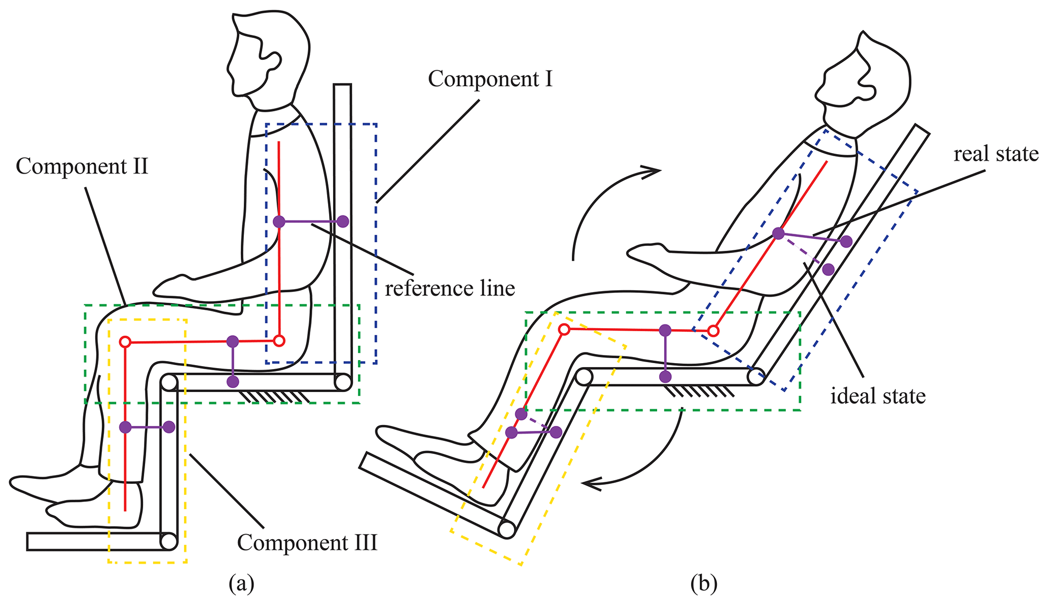
Figure 1Human–wheelchair coupling model. (a) Human–wheelchair coupling model in the sitting posture. (b) Human–wheelchair coupling model in the sit-to-lie posture.
According to our knowledge, the connecting points between the human and the wheelchair will be destroyed if the coupling knee joint and the coupling waist joint have a synchronous movement during the sit-to-lie transformation, as shown in Fig. 1b. The real position of the reference line is offset from the ideal position. Considering the problem of the misalignment of the rotation axis, linkage structures are added between each part of the wheelchair to match the human's joint rotation axis. Therefore, a new human–wheelchair coupling model is re-established (as shown in Fig. 2). There are two external degrees of freedom (DOF) that are added at the wrist joint and knee joint of the wheelchair, respectively. Therefore, each linkage structure at the coupling joint can be equivalent to two linkages connected by a rotating hinge. The DOF of this coupling model is as follows:
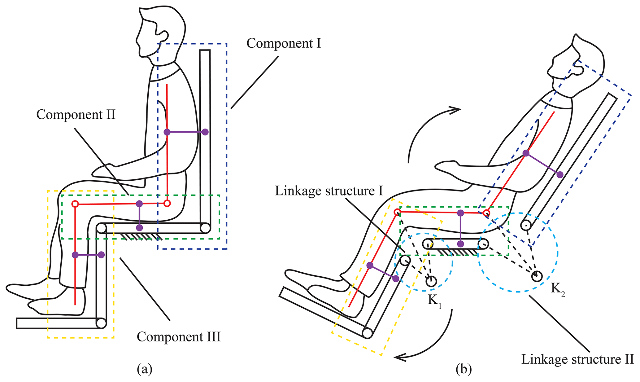
Figure 2Human–wheelchair coupling model II. (a) Human–wheelchair coupling model in the sitting posture. (b) Human–wheelchair coupling model in the sit-to-lie posture.
2.2 Sit-to-stand transformation
The other key problem with a multi-posture wheelchair is the CoG transformation in the sit-to-stand transformation. The human–wheelchair coupling model is built as shown in Fig. 3. When the person is in the sitting position, the person's CoG is behind the feet, and the weight of the entire body is mainly borne by the ischium (Wieczorek and Kukla, 2019). As shown in Fig. 3a, the CoG line g1 is at the rear end of the seat module. When the wheelchair transfers from sitting to standing, the leg module keeps still, and the seat module moves around the knee joint rotation axis until the standing position. As shown in Fig. 3b, the CoG line g2 is shifted in the middle of the person's feet, meaning that the wheelchair can fall over if the weight is not enough to compensate for the increment of the forward moment. Therefore, the gravity line should be moved backward to keep the balance during the sit-to-stand transformation. As shown in Fig. 3c, the position of the gravity line, g3, can be obtained according to the static analysis. In addition, the back module, the seat module, and the leg module are relatively independent to insure the posture transformation.
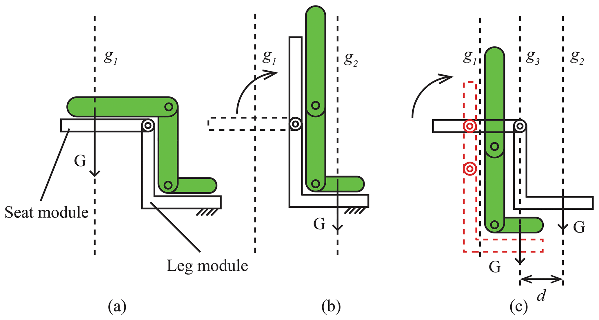
Figure 3Human–wheelchair coupling model III. (a) Schematic diagram of a person's CoG in the sitting posture. (b) Schematic diagram of a person's CoG in the standing posture (current wheelchair). (c) Diagram of a person's CoG in the standing posture (redesign of the seat module).
The sit-to-lie transformation and the sit-to-stand transformation have different features, based on the human–machine coupling model. This paper will discuss the configuration of the multi-posture wheelchair according to the three components as aforementioned in order to combine both features of the two coupling models.
3.1 Configuration of the back module
According to the movement characteristics of the sit-to-lie and sit-to-stand transformation, the remote-center-of-motion (RCM) mechanism (Fig. 4) is chosen (Pei et al., 2009; Hamlin and Sanderson, 1994; Yang et al., 2021) in this design. Considering that a simple RCM configuration needs a large range of motion to fix the linear actuator on the frame, we focus on the rigidity of the overall structure and avoid the singularity of the mechanism during the transformation process. Therefore, the back module adopts the scheme of a double parallelogram linkage structure. The configuration is composed of two congruent linkage structures, as shown in Fig. 4. The extension line of linkage Q2Q3 and linkage Q6Q7 intersect at point O, which is the virtual center of rotation of the back module. During the posture transformation of the back module, the position of the virtual rotation center point O is fixed. By establishing a virtual rotation center, this structure shifts the rotation center of the back module of the wheelchair upward. As long as the relationship between the length and the angle of the linkage structures are confirmed, the wheelchair's back module and the user's back rotation center can be fitted together, which improves the bionic performance and comfort of the wheelchair.
According to the structure diagram of the backrest mechanism, the relationship between the length of each linkage in the double parallelogram linkage structure and the center of rotation O can be obtained. Since the two parallelogram mechanisms are congruent, they are as follows:
Suppose the distance from the center of rotation O to the straight line ls of the seat is h1 and to the straight line lb of the backrest is h2, then the length relationship can be represented as follows:
where β1 is the angle between the seat and linkage Q3Q10, and β2 is the angle between the backrest and linkage Q7Q11.
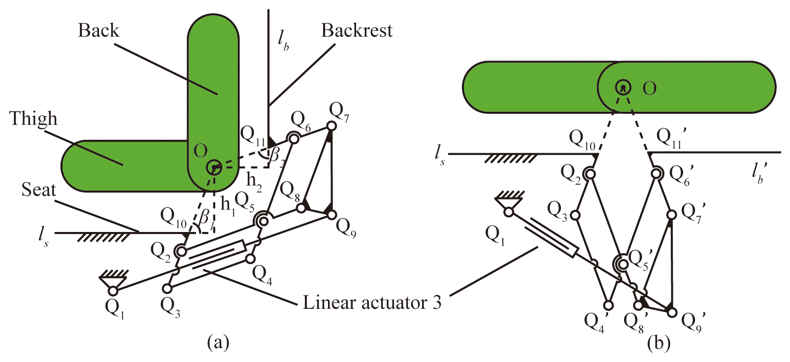
Figure 4Schematic diagram of the back module. (a) Schematic diagram of the back module at the sitting posture. (b) Schematic diagram of the back module at the lying posture.
3.2 Configuration of the leg module
In general, there are two configurations in the design of the leg module. In configuration I, as shown in Fig. 5a (Hwang and Jeon, 2012), the seat is the base, and the leg mechanism consists of a leg exoskeleton with a slider-crank mechanism. The rotation center of the wheelchair's leg module and the human's knee rotation center are directly matched to the same point. Therefore, the shift in the rotation center between the human and the wheelchair will be eliminated in the configuration. Configuration II, as shown in Fig. 5b, is similar to the configuration of the back module, which is an RCM consisting of a double parallelogram linkage mechanism. The leg module and the seat module are connected by a folding linkage structure instead of being directly hinged (Trkla, 1990). The human leg elongation can be compensated by opening the folding linkage structure during the sit-to-lie and sit-to-stand transformations. Both configurations can solve the problem of the misaligned axis; however, the configurations cannot fit the shift in the CoG in the sit-to-stand transformation. Combining the characteristics of the posture transformation and the range of motion of the knee joint, this paper proposes a six-bar configuration composed of a folding linkage structure and a slider based on configuration II, as shown in Fig. 6. The deviation between the human knee joint and the wheelchair leg module can be compensated by the folding linkage and the slider (the linear actuator). In addition, the shift in the CoG cannot affect the leg module because of the slider H. Such a design ensures the stability of the leg module and simplifies the mechanical structure.
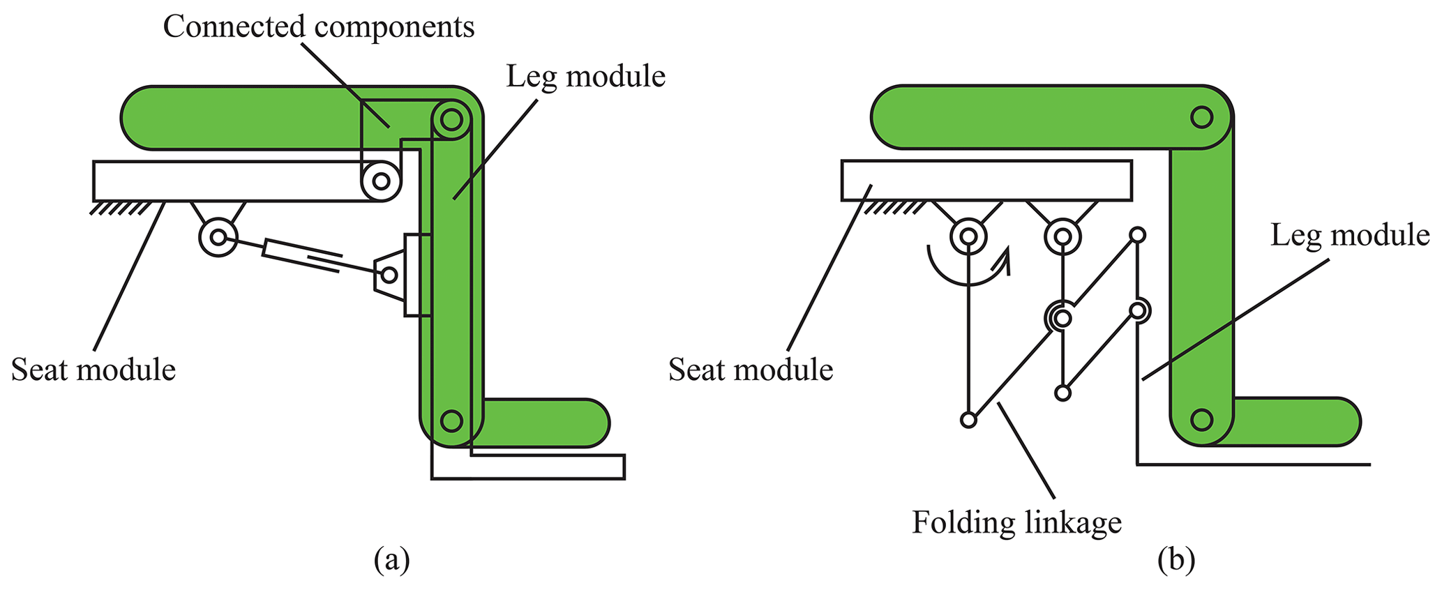
Figure 5The general configuration of the leg module. (a) Configuration I. (b) Configuration II.
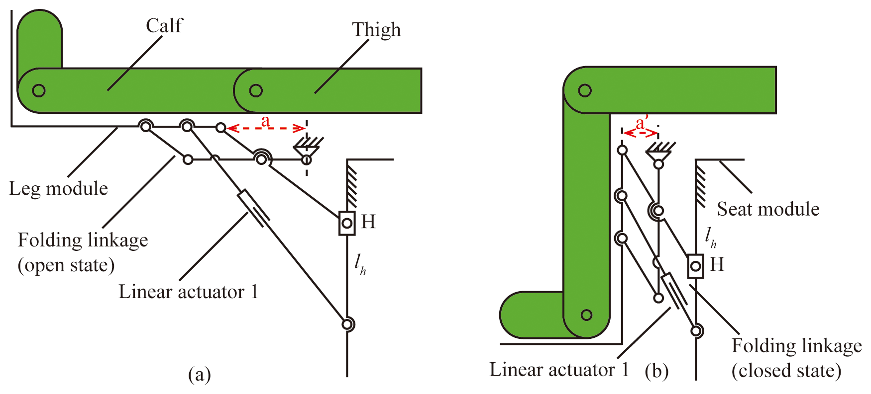
Figure 6The configuration of the leg module with configuration III. (a) Schematic diagram of the leg module at the lying posture. (b) Schematic diagram of the leg module at the sitting posture.
3.3 Configuration of the seat module
According to the configurations of the back module and the leg module, the seat module, as the base mechanism, consists of a parallelogram linkage mechanism (as shown in Fig. 7). In the parallelogram linkage mechanism, linkage R2R5 is a virtual constraint and is fixed to the wheelchair's chassis module. The straight line lh fixed to the leg module is connected to linkage R1R6. Since the leg module is located on the straight line lh and is fixed to linkage R1R6, the leg module moves to the bottom right as the parallelogram linkage structure rotates, remaining upright throughout the movement. The seat module rotates around the virtual restraint linkage R2R5, which ensures that the person's CoG can move backward in the sit-to-stand transformation. The length of linkage R1R2 is the shifting distance of the CoG.
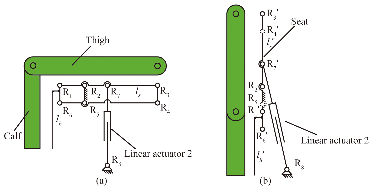
Figure 7The configuration of the seat module. (a) Schematic diagram of the seat module at the sitting posture. (b) Schematic diagram of the seat module at the standing posture.
3.4 The configuration of the wheelchair
The configuration of the posture transformation wheelchair is shown in Fig. 8. The leg module is located on the straight line lh, and the back module is located on the straight line ls. To show the structure clearly, the mechanical structure of the chassis module is omitted. The whole wheelchair is mainly powered by three linear actuators.
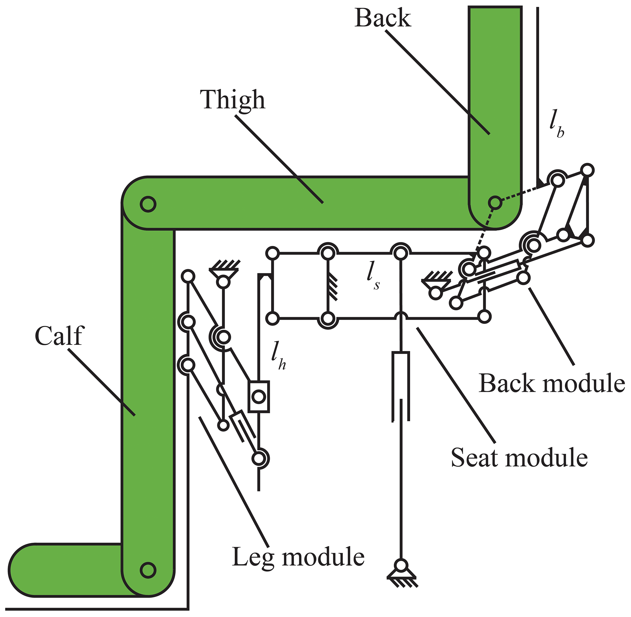
In the multi-posture wheelchair configuration, as demonstrated in Fig. 8, there are 3 DOF in this mechanism to implement the sit-to-lie and sit-to-stand transformations. A total of three linear actuators are utilized in this mechanism. In the sit-to-lie transformation, it is necessary to analyze the kinematics of the leg module and the back module because there is only the joint transformation. In the sit-to-stand transformation, the kinematics of the back module and the seat module should be analyzed together to define the shift in the CoG. Therefore, this paper analyses the kinematics of the leg module, the back module, and the seat module for the sit-to-lie transformation and the sit-to-stand transformation.
4.1 Kinematic analysis of the leg module
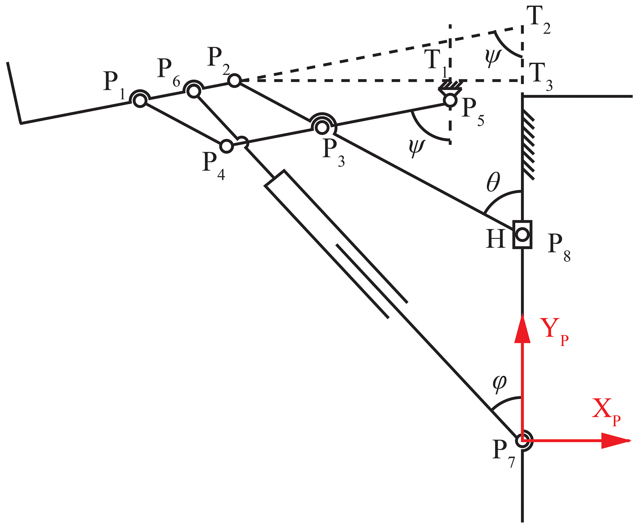
Since the leg module is driven by linear actuator 1, the rotation angle of the leg module and the extension compensation distance of the linkage structure can be expressed by the stroke of linear actuator 1. As shown in Fig. 9, P7 is the one fixed point of linear actuator 1. P8 is the position coordinate point of the slider H. Here, a coordinate P7–XPYP is located at point P7. Vectors , , , represent the vectors of point P5, P8, P2, and P6 with respect to the origin in the coordinate. Here, is constant.
To ensure the stability of the leg structure and reduce the complexity of movement, the other fixed point of linear actuator 1 is installed at P6, which is the middle point of linkage P1P2. There are two extension lines, P2T2, P8T2, made to figure out the relationship between the motion of the leg module and the stroke of the linear motor. T2 is the intersection of the extension line of linkage P1P2 and linkage P7P8. In addition, line P2T1 is perpendicular to line T1P5, and line P2T3 is perpendicular to line T1T3, i.e., and . ψ represents the rotation angle of the leg module, and φ represents the rotation angle of linear actuator 1 in this figure. The range of ψ is from 0 to 90∘.
Therefore, in the following:
where and are constant, and θ represents the angle between linkage P2P8 and the plumb line.
In solving Eqs. (5)–(7), the compensation amount of the leg module can be expressed as follows:
For linear actuator 1, its stroke can be obtained as follows:
where is the initial length of linear actuator 1, and Δt1 is defined as the stroke of linear actuator 1.
Linkage P3P5, linkage P3P8 and slider H form an offset crank slider mechanism, so the relationship between ψ and θ can be expressed as follows:
where and are constant.
The relationship between the rotation angle of the leg module ψ and the feed length of linear actuator 1Δt1 can be expressed as follows:
The stroke of slider H is also a factor that we need to consider. Since linkage P3P5 is initially in a vertical state and ends in a horizontal state, the stroke of slider H can be explained as follows:
where θ0 is the initial angle between linkage P2P8 and the plumb line.
4.2 Kinematic analysis of the back module
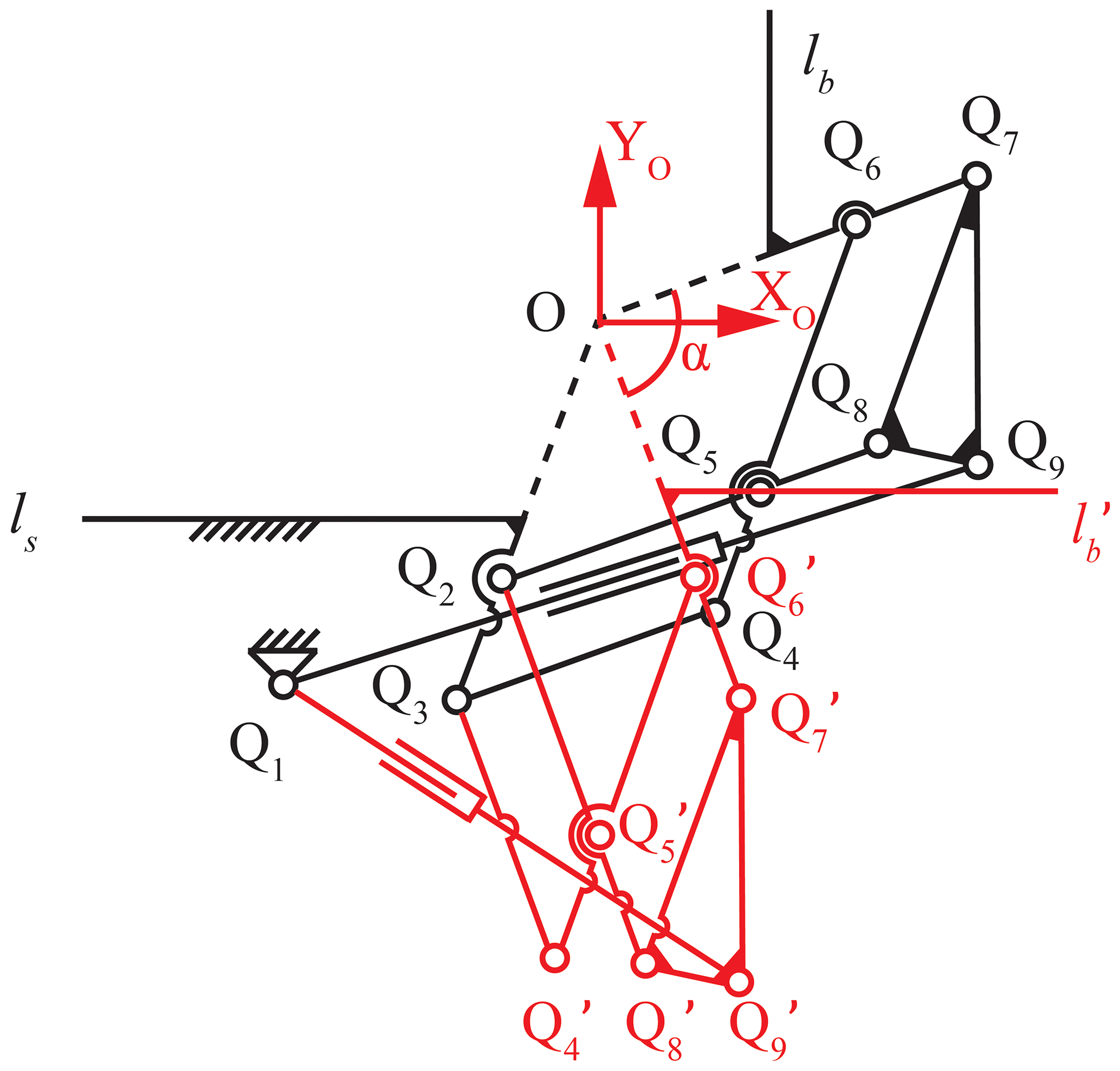
As shown in Fig. 10, the black lines show the state of the wheelchair in the sitting posture, and the red lines represent the state of the wheelchair in the lying posture. We take the virtual rotation center O of the back module as the origin to establish a coordinate system. Linkage Q7Q9 always stays upright, and its length is fixed. α represents the rotation angle of the back module. Here, the vector , , represents the vectors of points Q7, Q1, and Q9 with respect to the origin in the coordinate O−XOYO.
The rotated coordinates of points and can be expressed as follows:
The initial length of linear actuator 3 and the length during movement can be obtained according to the coordinates of points Q1, Q9, and as follows:
where Δt3 represents the feed length of linear actuator 3.
In solving Eqs. (15)–(17), the relationship between Δt3 and α can be expressed as follows:
where, in the following:
4.3 Kinematic analysis of the seat module
As shown in Fig. 11, the black lines represent a random posture of the wheelchair, and the red lines represent the wheelchair in sitting posture.
The total length of linear actuator 2 can be expressed as follows:
where represents the initial length of linear actuator 2, and Δt2 represents the stroke of linear actuator 2.
Therefore, the initial angle between linkage and line R2R8 can be obtained as follows:
The rotation angle of the seat γ can be obtained as follows:
In solving Eqs. (24)–(25), the relationship between Δt2 and γ can be expressed as follows:
which means that the rotation angle of the seat can be changed by controlling the feed length of linear actuator 2.
In addition, the distance of the person's CoG moves back can be expressed as follows:
The maximum value is obtained when the wheelchair is in a standing posture.

4.4 Optimization of the leg module
The kinematic analysis of the leg module confirmed the feasibility of the design. However, to achieve the improvement of the bionic effect, it is necessary to optimize the length of each linkage of the leg module to further fit the user's real motion trajectory and to ensure the user's comfort and safety during the use.
As shown in Fig. 12, a simplified diagram of the human–machine coupling motion of the leg module is established. Here, the leg module model is simplified in order to facilitate theoretical analysis. The coordinate P5-XY is set at point P5. Point Mi represents a reference point on the foot pedal of the leg module, ψ1 is the angle between linkage P4P5 and the y axis, and θ1 is the angle between linkage P2P8and the y axis.
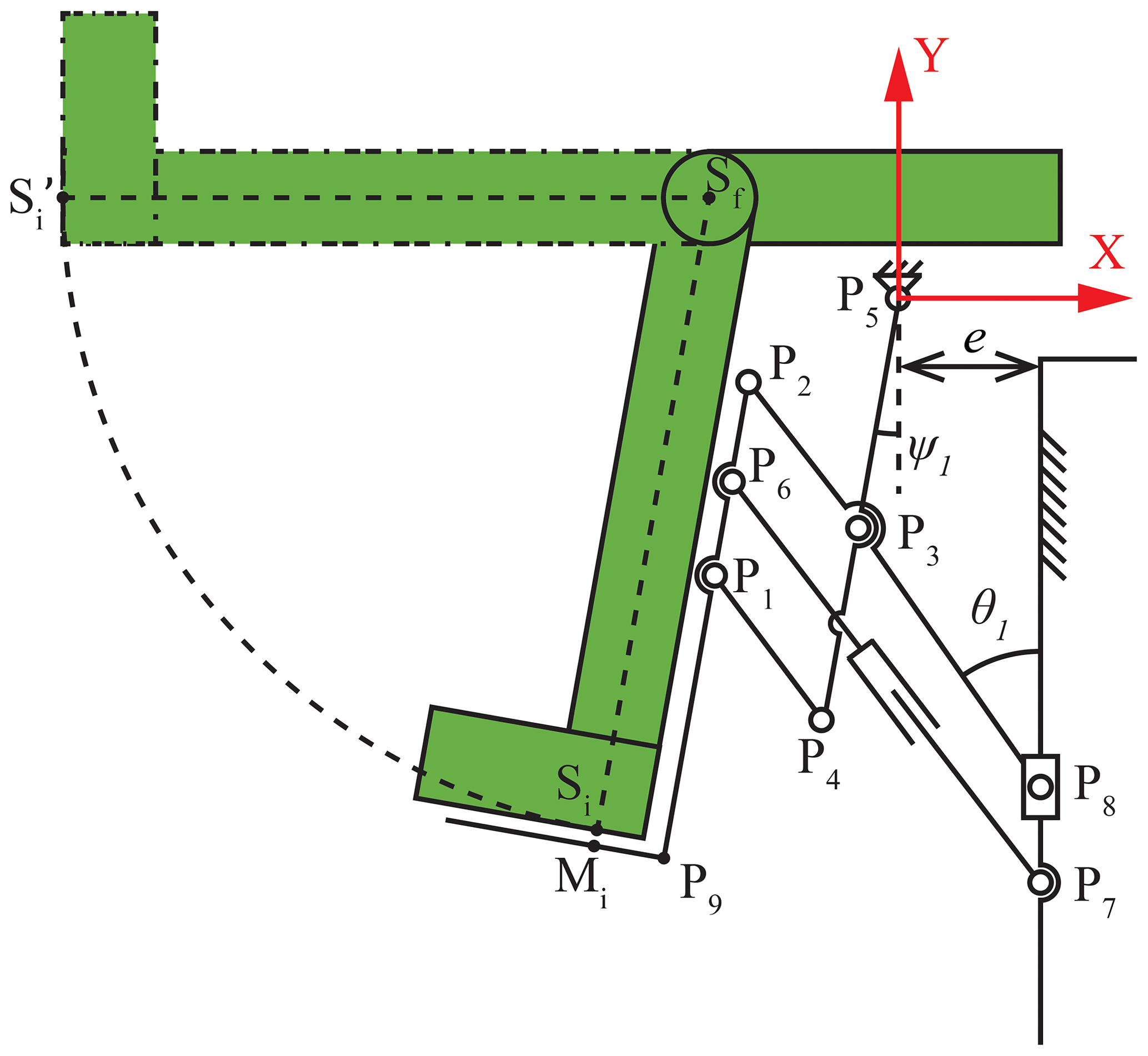
Point Sf is the center of rotation of the user's calf. According to the main body size relationship table of adult males aged 18 to 60 years (CSBTS, 1988), the median of the population was chosen in this paper. So the length of the calf and foot is defined as 420 mm. So, the trajectory of the person's foot point Si is as follows:
According to the geometric relationship of the linkages, the coordinates of Mi are related to the length and position of each linkage; that is, the coordinates of Mi depends on , , , , , , and e. Therefore, the design variables can be obtained as follows:
In order to obtain the optimization, 10 discrete points of Si on the point motion trajectory were chosen here. Therefore, the root mean square function relation of the coordinate value error between point Mi and point Si can be expressed as follows:
According to the geometric configuration restriction of the leg module, the constraint condition on the length of the linkages can be expressed as follows:
Considering that minf(X) is a multivariable nonlinear function, the sequential quadratic programming (SQP) algorithm is used to optimize it (Urueña et al., 2009). The initial value of is set in this paper.
The optimal solution is obtained as follows:
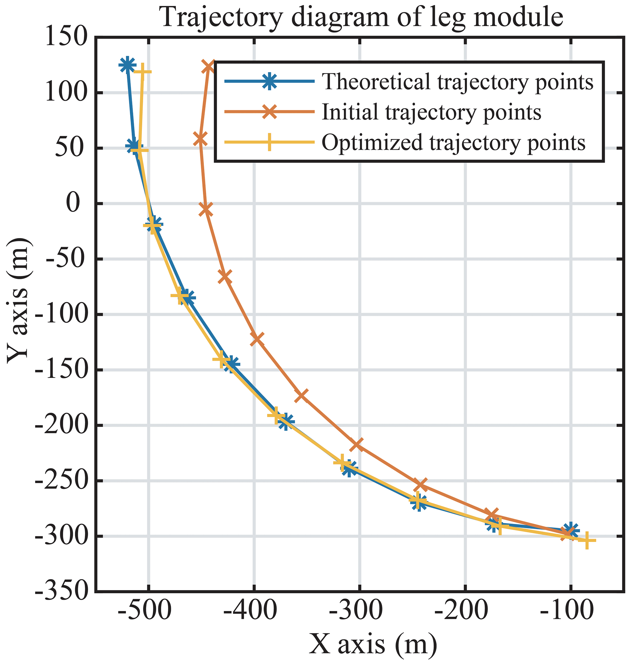
Figure 13 shows that the trajectory obtained by the optimized geometrical size of the leg module is more of a match to the desired trajectory than the theoretical trajectory.
5.1 The implementation of the optimal multi-posture wheelchair
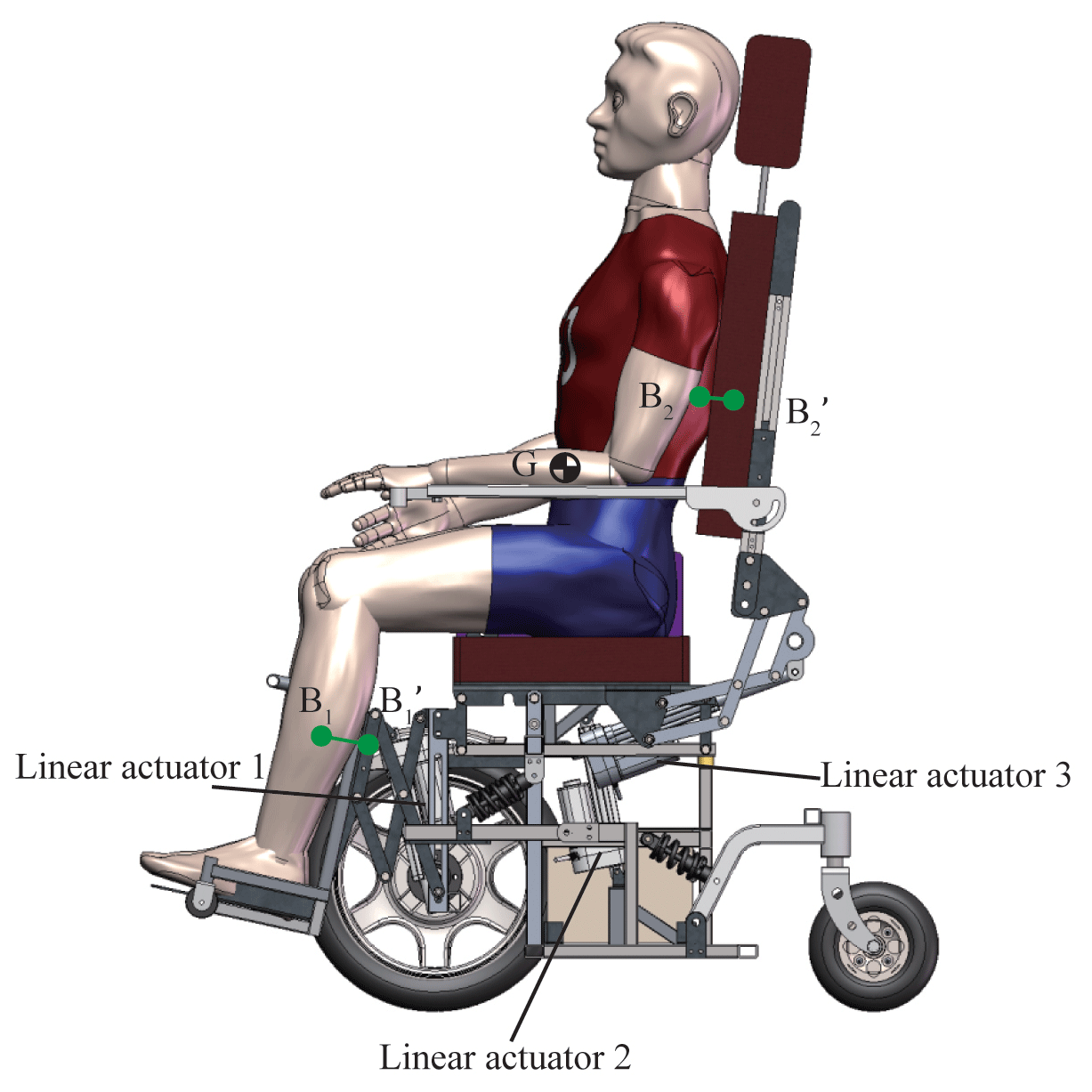
To evaluate the consistency of the motion centers between the human and the wheelchair and the shifting CoG of the human on the proposed wheelchair, a 3-D model is designed in the software SolidWorks, as shown in Fig. 14. There are three linear motors chosen in this design to implement the sit-to-lie and sit-to-stand transformations. According to the optimization results, the strokes of the three linear motors (manufactured by Zhejiang Jiecang linear motion technology co., ltd; JC35W2) are chosen as 120, 120, and 150 mm, respectively.
Several points on the human and the wheelchair are set up to evaluate the consistency of the motion centers between human and the wheelchair and the shifting CoG of the human on the proposed wheelchair. Points B1 and B2 are set on the user's calf and back in the model. Their corresponding points and are set on the leg module and back module of the proposed wheelchair. Point G is set up at the human's CoG.
5.2 Simulation evaluation of the consistency of motion centers
The human–wheelchair coupling model is imported into the simulation software Adams (Automatic Dynamic Analysis of Mechanical Systems). Assuming that the person weighs 70 kg, the leg module movement is moving with uniform motion in a straight line at a speed of 7.5 mm s−1 for 20 s. The back module is moving with a uniform motion in a straight line at a speed of 6 mm s−1 for 20 s.
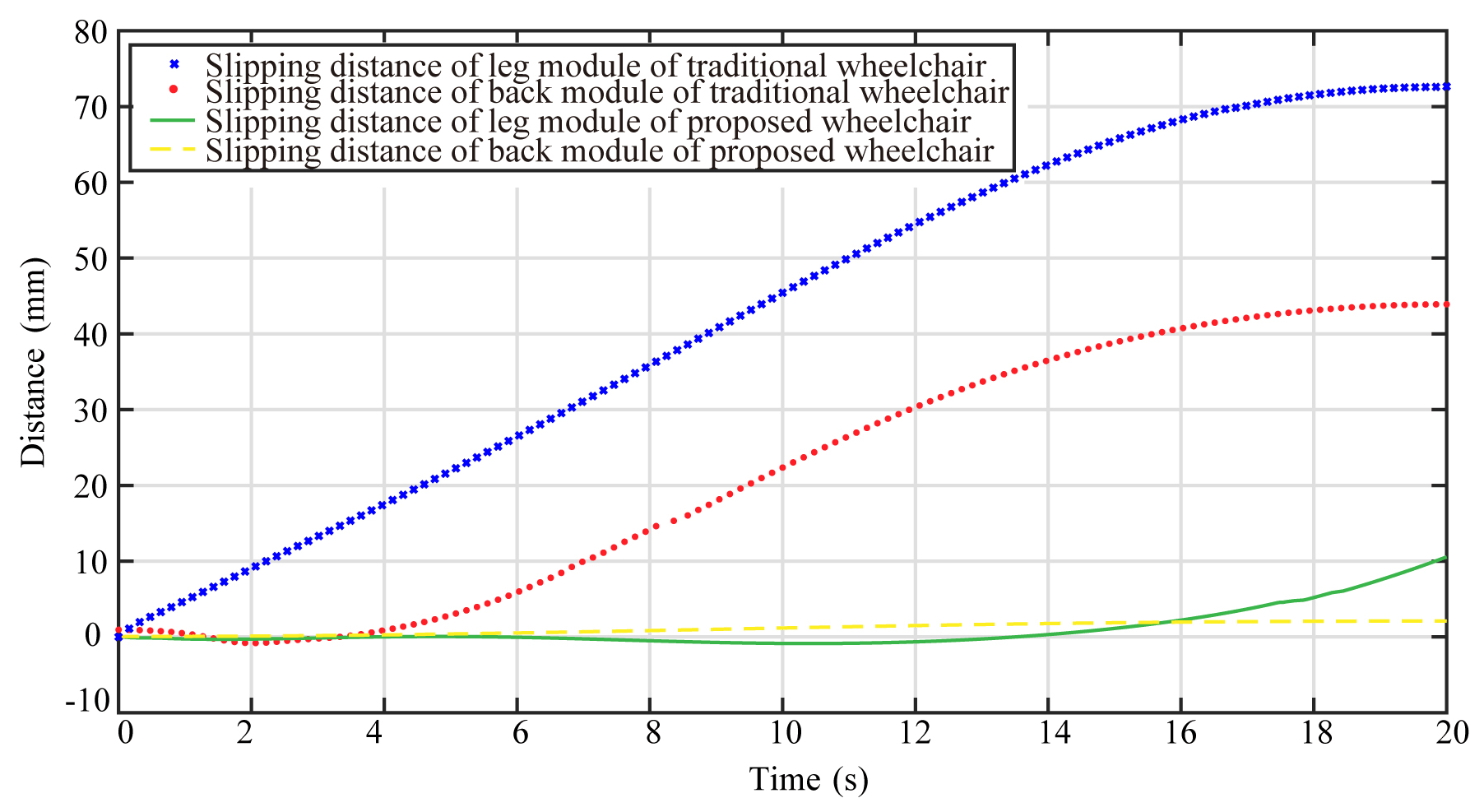
In the sit-to-lie transformation, the slipping distance between point B1 and point , i.e., the slipping distance between the human leg and the wheelchair leg modular, is shown in Fig. 15 with the red line. The simulation result shows that slipping distance changes little at first and gradually increases after 10 s. The maximum slipping distance is 10.5 mm at the terminal state. Similarly, the slipping distance between point B2 and point , i.e., the slipping distance between the human back and the wheelchair back modular, is shown in Fig. 15 with the blue dotted line. The simulation result shows that the slipping distance increases slightly and reaches a maximum at the end. The maximum slipping distance is 2.1 mm.
Comparing the simulation results of the leg curve and back curve, the trend of back slipping is less than the trend of leg sipping because of the different design structure. However, all changes are within acceptable limits, and there is room for further refinement of the leg module.
As a comparison, we tested the slipping distance of a traditional wheelchair (Jerry Medical Instrument (Shanghai) Co., Ltd.; model JRWD1003). Through measurement, the slipping curve is obtained, as shown in Fig. 15. In the process of posture transformation, the slipping distance of the leg module is 72 mm and that of the back module is 44 mm. Through comparison, it can be seen that the wheelchair proposed in this paper greatly reduces the slipping distance of the wheelchair in the process of posture transformation and improves the bionic performance and comfort of the wheelchair.
5.3 Simulation analysis of sitting–standing posture transformation
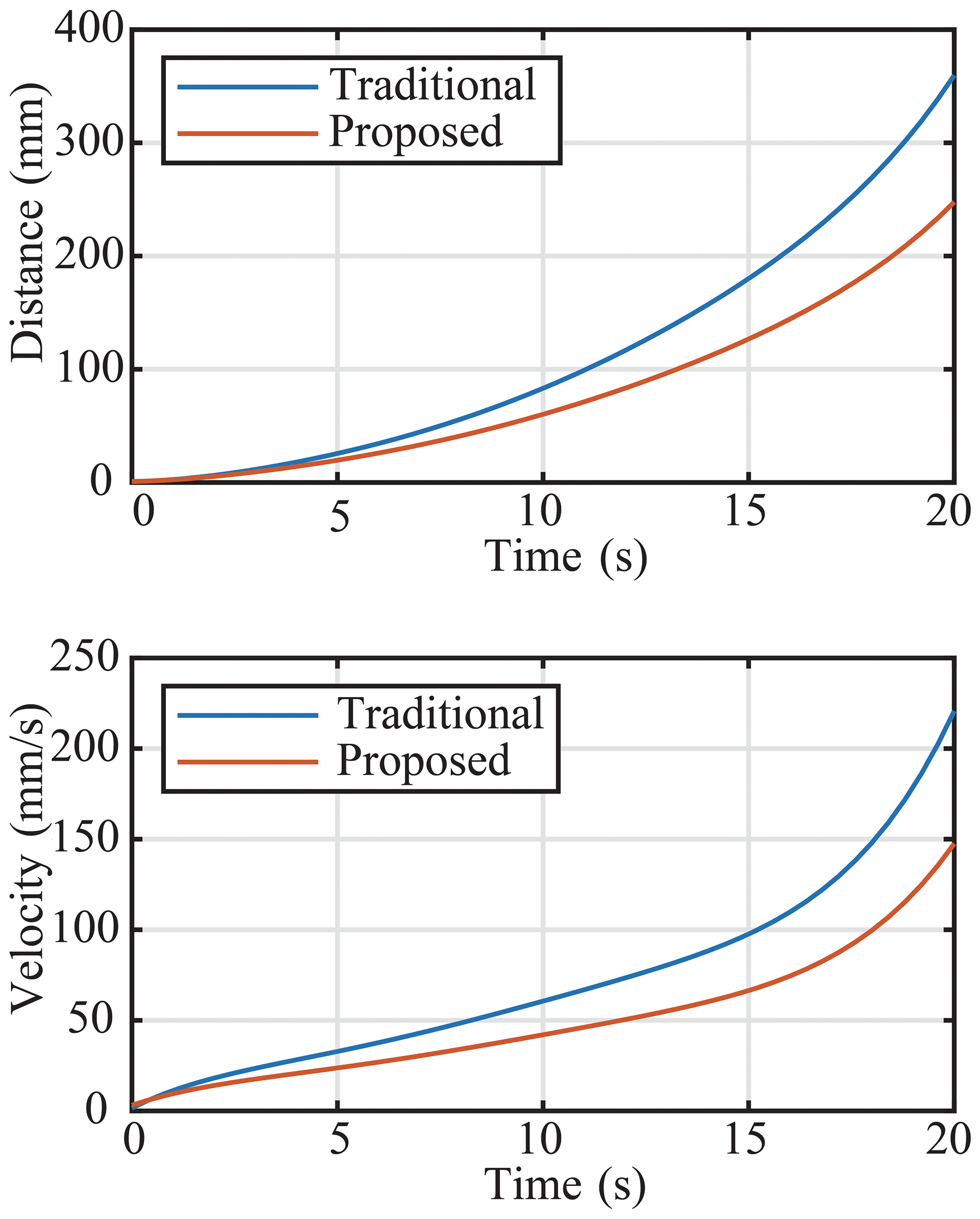
The human–wheelchair coupling model is imported into the simulation software ADAMS. Assuming that the person weighs 70 kg, the seat module movement is moving with uniform motion in a straight line at a speed of 6 mm s−1 for 20 s. At the same time, to explore the optimization effect of the proposed wheelchair, as a control experiment, a traditional wheelchair is also simulated under the same conditions.
In the sit-to-stand transformation, the moving distance of the CoG on the x axis is shown in Fig. 16, where the red line represents the proposed wheelchair and the blue line represents a traditional wheelchair. The simulation result shows that the maximum moving distance of the CoG of two wheelchairs is obtained at the end. It is noted that the moving distance of the CoG of the proposed wheelchair is less than that of a traditional wheelchair's, and at the end, the distance is reduced by 112.4 mm, which represents how the design goal of moving the CoG backward is realized. At the same time, the motion characteristics of the two wheelchairs are further analyzed. It can be seen that the speed of the proposed wheelchair in the running process is less than that of the traditional wheelchair, which ensures the motion stability of the wheelchair and improves the safety of the wheelchair.
This paper proposes a sitting–standing–lying posture bionic transformation for a multi-posture wheelchair based on the movement characteristics of the human–wheelchair coupling model. The two solutions to improve the nature motion capability of the multi-posture wheelchairs are of keeping the joints' rotation centers the same as the human being's joints and the of adjusting the CoG of the user. There are three modules in the design of the multi-posture wheelchair, i.e., the back module, the seat module, and the leg module. The three modules can implement the transformations of sit-to-lie and sit-to-stand transformations by moving together synergically. The configuration of the transformation mechanism is chosen by comparing the trails of the wheelchair rotation centers and the corresponding human joint rotation centers. The kinematics of the optimized configuration is discussed in detail to obtain the most bionic motion performance using the multivariable nonlinear constraint optimization algorithm. Finally, the mechanism is designed, and its posture transformation performance is simulated and verified using ADAMS software. In the future, a voice control module and a radar module will be installed on the wheelchair to enable intelligent control of the wheelchair. A prototype will also be made, and the structure of the wheelchair will be further optimized.
All the data used in this article can be obtained upon request from the corresponding author.
QM proposed and developed the overall concept of the paper and conducted the mechanism design and analysis. MJ helped write and edit the paper. HY supervised and structured the paper. ZJ helped to process the data.
The contact author has declared that neither they nor their co-authors have any competing interests.
Publisher's note: Copernicus Publications remains neutral with regard to jurisdictional claims in published maps and institutional affiliations.
This research has been supported by the National Key Research and Development Program of China (grant no. 2020YFC2007501).
This research has been supported by the National Key Research and Development Program of China (grant no. 2020YFC2007501).
This paper was edited by Guowu Wei and reviewed by two anonymous referees.
Cao, W., Yu, H., Wu, X., Li, S., and Chen, C.: Voice controlled wheelchair integration rehabilitation training and posture transformation for people with lower limb motor dysfunction, Technol. Health Care., 29, 609–614, https://doi.org /10.3233/THC-202386, 2020.
CSBTS (State Bureau of Technical Supervision): China Standards Press: 88: GB 10 000, Chinese adults body size [S]. Diss., 1988 (in Chinese).
Dawar, G. and Kejariwal, A. D.: Design of a modular wheelchair with posture transformation capabilities from sitting to standing, Disabil. Rehabil. Assist. Technol., 15, 670–683, https://doi.org/10.1080/17483107.2019.1604830, 2020.
Hamlin, G. J. and Sanderson, A. C.: A novel concentric multilink spherical joint with parallel robotics applications, IEEE Int. Conf. Rob., San Diego, CA, USA, 8–13 May 1994, 1267–1272, https://doi.org/10.1109/ROBOT.1994.351313, 1994.
Hwang, B. and Jeon, D.: A wheelchair integrated lower limb exercise/rehabilitation system: Design and experimental results on the knee joint, IEEE/SICE International Symposium on System Integration (SII), Fukuoka, Japan, 16–18 December 2012, https://doi.org /10.1109/SII.2012.6427375, 2012.
Goher, K. M.: A reconfigurable wheelchair for mobility and rehabilitation: Design and development, Cogent Eng., 3, 1261502, https://doi.org/10.1080/23311916.2016.1261502, 2016.
Kovindha, A., Kammuang-Lue, P., Prakongsai, P., and Wongphan, T. J. S. C.: Prevalence of pressure ulcers in Thai wheelchair users with chronic spinal cord injuries, Spinal Cord, 53, 767–771, https://doi.org/10.1038/sc.2015.77, 2015.
Pei, X., YU, J., BI, S., and Z, G.: Type Synthesis for One-dimensional Remote-center-of-motion Mechanisms, Chin. J. Mech. Eng., 45, 144–148, https://doi.org/10.3901/JME.2009.02.144, 2009.
Peng, S. W., Lian, F. L., and Fu, L. C.: Mechanism Design and Mechatronic Control of a Multifunctional Test Bed for Bedridden Healthcare, IEEE-ASME T. MECH., 15, 234–241, https://doi.org/10.1109/TMECH.2009.2021470, 2010.
Song, Z., Tian, C., and Dai, J. S.: Mechanism design and analysis of a proposed wheelchair-exoskeleton hybrid robot for assisting human movement, Mech. Sci., 10, 11–24, https://doi.org/10.5194/MS-10-11-2019, 2019.
Sprigle, S., Mcnair, D., and Sonenblum, S.: Pressure Ulcer Risk Factors in Persons with Mobility-Related Disabilities, Adv. Skin Wound Care, 33, 146–154, https://doi.org/10.1097/01.ASW.0000653152.36482.7d, 2020.
Tessa, G. and Mao, J.: Muscle atrophy and procedures for training after spinal cord injury, Phys. Ther., 74, 50–60, https://doi.org/10.1093/PTJ/74.1.50, 1994.
Trkla, T. A.: All purpose wheelchair, US4949408 A, 1990.
Urueña, C., Daza, C., and Alvarado, D.: Application of sizing design optimization to position and velocity synthesis in four bar linkage, Rev. Fac. Ing. Univ. Antioquia N., 40, 129–144, https://doi.org/10.1348/014466505X86672, 2009.
Wieczorek, B. and Kukla, M.: Effects of the performance parameters of a wheelchair on the changes in the position of the centre of gravity of the human body in dynamic condition, PLoS ONE, 14, e0226013, https://doi.org/10.1371/journal.pone.0226013, 2019.
Wu, Y., Song, Y., and Yu, T.: Spatial Differences in China's Population Aging and Influencing Factors: The Perspectives of Spatial Dependence and Spatial Heterogeneity, Sustainability, 11, 5959, https://doi.org/10.3390/su11215959, 2019.
Yang, Y., Liu, H., Zheng, H., Peng, Y., and Yu, Y.: Two types of remote-center-of-motion deployable manipulators with dual scissor-like mechanisms, Mech. Mach. Theory, 160, 104274, https://doi.org/10.1016/J.MECHMACHTHEORY.2021.104274, 2021.
Zhang, J.: Data Analysis of National Disabled People's Basic Database, Disabil. Res., 3, 76–79, 2013.
- Abstract
- Introduction
- Human–wheelchair coupling model
- Configuration synthesis of the multi-posture wheelchair
- Kinematic analysis of the multi-posture wheelchair
- Simulation experimental evaluation
- Conclusions and future work
- Data availability
- Author contributions
- Competing interests
- Disclaimer
- Acknowledgements
- Financial support
- Review statement
- References