the Creative Commons Attribution 4.0 License.
the Creative Commons Attribution 4.0 License.
 | 10 Nov 2021
Synthesis method of two translational compliant mechanisms with redundant actuation
Shihua Li
Yajie Zhou
Yanxia Shan
Shuang Chen
Jinhan Han
In the fields of electronic packaging, micromanipulation, scanning, and two translational (2T) mechanisms are required, especially with high stiffness, for a large workspace, with good driving stability, and other occasions. Redundant actuators are required to improve the performance of the 2T compliant parallel mechanism. The novelty of the work is to propose a new method for the type synthesis of a 2T redundant actuated compliant parallel mechanism based on the freedom and constraint topology (FACT) approach and the atlas approach. The synthesis conditions are given, and the synthesis process is formulated. With this method, new 2T redundant actuated compliant parallel mechanisms are synthesized. Some new mechanisms have been synthesized, which enriches the compliant parallel mechanism configurations. Based on the atlas method, the synthesized mechanism is analyzed. The results verify the correctness and effective of the synthesis method. The method is also suitable for a type of synthesis of redundant actuated compliant parallel mechanisms with 3, 4, 5, and 6 degrees of freedom (DOF), respectively.
- Article
(4373 KB) - Full-text XML
- BibTeX
- EndNote


XY-compliant parallel mechanisms (CPMs) have been extensively used in a variety of applications, such as atomic force microscopes (Zhang et al., 2017; Hao, 2014), micro-assembly (Liu et al., 2017), and data storage (Qin et al., 2013; Tian et al., 2014). They transfer and transform the motion/load through the elastic deformation of flexible members and are parallel-type manipulators. Their merits include eliminated backlash and friction, no need for lubrication, reduced wear and noise, and monolithic configuration (Clark et al., 2016). However, the applications of compliant mechanism are limited because it is hard to make a precision micro-positioning system with both a large workspace and high carrying capacity at the same time.
According to previous work (Awtar and Slocum, 2007; Hao and Yu, 2016; Wan and Xu, 2016; Choi et al., 2012; Du and Li, 2020; Lai and Zhu, 2017), the workspace of such mechanisms is largely dependent on the type of flexure hinge. In traditional designs, different flexure hinges are used. Then, flexure hinges with well-defined rotation axes are used to replace conventional revolute joints in rigid-body mechanism configurations. For example, a multi-axis, large-output XY compliant mechanism is proposed (Hao, 2017). This design is achieved by replacing each rigid P joint with the basic parallelogram module. A novel, large-range XY CPM with enhanced out-of-plane stiffness is proposed (Hao and Kong, 2012). The mechanism uses planar double multi-beam parallelogram modules (DMBPMs) to construct compliant P joints. A piezoelectric robot with four parallel legs operating in a rowing mechanism is presented and tested (Deng et al., 2019). A novel flexure parallel kinematics precision positioning stage with a centimeter range and compact dimension is presented. The experimental results demonstrate that the stage is capable of positioning with a workspace over 11 mm × 11 mm (Xu, 2013). A new large-stroke XY micro-positioning stage is proposed. The XY stage is based on serially arranged compliant mechanisms with flexure hinges. A stroke of 20 mm within a 10 µm positioning deviation is achieved in both axes (Gräser et al., 2021). A large range-compliant XY nano-manipulator is proposed. The mechanism can achieve millimeter strokes and high natural frequency (Liu and Zhang, 2021). According to the above, most large-stroke compliant mechanisms improve the workspace mainly through using the plate flexible hinges or adding the displace amplification mechanism. And, a small workspace is one of main restrictions on the application of compliant mechanisms.
On the other hand, it is challenging to devise a compliant micro-positioning stage with high carrying capacity. For rigid-body mechanism, the carrying capacity can be improved by using a redundant actuator (Qi et al., 2019a, b, 2020; Wang et al., 2020; Tan et al., 2019). For the compliant mechanism, a 3-PUPU compliant parallel mechanism is proposed, which adopts a dual-drive scheme (Yun and Li, 2011). Based on the 3-PUS/PU parallel mechanism, a new compliant parallel mechanism with redundant actuation is proposed. And, the driving stability of the mechanism is proved through the analysis of the kinematics (Mahl et al., 2012). A 4-PPR compliant parallel mechanism with redundant actuation is proposed (Yang et al., 2019). Its kinematics and static stiffness are analyzed, and the results prove that the mechanism has decoupling characteristics and a compact structure. A 3 degrees of freedom (DOF) compliant parallel mechanism with redundant actuation is proposed to improve the workspace and carrying capacity (He and Zhen, 2007; Fan, 2006). A compliant mechanism realizes the redundant actuation through shape memory alloy (SMA) actuation (Kittinanthapanya et al., 2019). A dual-drive compliant robot is analyzed. The results demonstrate that the redundant actuated mechanism can achieve driving force optimization and control (Tagliamonte et al., 2012). An integral optical micro-adjustment mechanism with redundant actuation is proposed (Zhang and Zhao, 2014; Dong et al., 2017). However, most of the redundant actuated compliant parallel mechanisms are proposed based on rigid-body mechanism with redundant actuation, and there is no a systematic method for the type synthesis of a redundant actuated compliant parallel mechanism.
To this end, a conceptual design method is proposed in this research. And, a new two translational (2T) redundant actuated compliant parallel mechanism is synthesized. The remaining parts of the paper are organized as follows. Section 2 is based on the freedom and constraint topology (FACT) approach and the atlas approach, a new method for type synthesis of redundant actuated compliant parallel mechanism is proposed, the synthesis conditions are given, and the synthesis process is formulated. Section 3 discusses how, with this method, new 2T redundant actuated compliant parallel mechanisms are synthesized. In Sect. 4 the synthesized mechanisms are analyzed to verify the correctness and rationality of the proposed type synthesis method.
2.1 Rule of complementary patterns
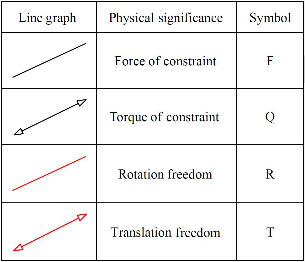
In order to visualize the relationship between freedoms and constraints in a mechanical system, Blanding (1999) introduced both constraint lines and freedom lines, as shown in Table 1. At the meantime, he addressed the rule of complementary patterns (Blanding rule) that states that every freedom line intersects all constraint lines.
Based on the visual-constraint-based design method, Hopkins and Culpepper (2010a, b) extended this method and further proposed a FACT approach to achieve a visual-type synthesis of compliant mechanisms. For this purpose, they denoted a collection of commonly used freedom and constraint screw sets as freedom spaces (FSs) and constraint spaces (CSs), respectively, and established luxuriant patterns representing the unique mapping between FSs and their complementary CSs.
2.2 Synthesis conditions of the mechanism
Some synthesized conditions are introduced for a redundant actuated compliant parallel mechanism. Firstly, the number of redundant actuated motion pairs need to be determined. Then, the number of compliant branches need also to be determined. Finally, the arrangement of compliant branches needs to be selected.
According to the principle of independent drive, the principle of symmetry, and the minimum principle of redundant actuated motion pairs, the number of the redundant actuated motion pairs is obtained. For the principle of independent drive, the dimensional remains unchanged for the constraint space and freedom space of the mechanism when the mechanisms add the redundant actuated motion pairs. For the principle of symmetry, the precision performance and the stiffness performance can be improved. Parasitic motion is an inherent property of the compliant mechanism. It affects the accuracy of the compliant mechanism. But for the asymmetric compliant mechanism, an uneven force is present. Thus, the parasitic motion cannot be ignored. The symmetrical compliant mechanism can answer the problem of the uneven force and cause a little parasitic motion. Moreover, the parasitic motion of the asymmetric compliant mechanism can be compensated by symmetric arrangement. Thus, the symmetrical compliant mechanism can improve the precision performance. For the minimum principle of redundant actuated motion pairs, the number of redundant actuated motion pairs can be confirmed further.
First, we obtain the range of the number of redundant actuated motion pairs by the principle of symmetry. Then, we obtain the range of the number of redundant actuated motion pairs by the principle of independent drive. Finally, the particular value is obtained by the minimum principle of redundant actuated motion pairs. Thus, the number of redundant actuated motion pairs, W, was determined.
When the number of redundant actuated motion pairs and the DOF of the mechanism is determined, the number of the compliant branches, n, is determined. Thus, the number of compliant branches, n, is expressed as follows:
where M is the DOF of the mechanism, and W is the number of redundant actuated motion pairs.
In order to ensure that the synthesized mechanisms meet the requirements of the DOF, the branches of the mechanism need to be reasonably arranged.
Assuming that the mechanism can achieve the desired motion, the relationship needs to be satisfied among the constraint spaces of all compliant branches and the constraint space of moving platform, which is written as follows:
where Cm denotes the constraint space of the moving platform, ) denotes the constraint space of the compliant branch, and ∪ denotes the union set operation.
2.3 Synthesis process
In this paper, a new synthesized method is proposed. New 2T redundant actuated compliant parallel mechanisms are introduced based on the proposed method. The process for the type synthesis is presented as follows.
-
Step 1: specify the freedom space of the moving platform according to desired DOF M of the mechanism. Then, determine the reciprocal constraint spaces and all possible same-dimensional constraint spaces by using the Blanding rule.
-
Step 2: generate a complete fundamental building block (FBB) library in terms of decomposing for the CSs obtained from step 1.
-
Step 3: determine the number of the redundant actuators W according to the principle of independent drive, the principle of symmetry, and the minimum principle of redundant actuated motion pairs. Then, the symmetric CSs selected under W are known.
-
Step 4: obtain all sub-constraint spaces based on the symmetric CSs and the fundamental building block. Then, determine the reciprocal sub-freedom spaces by using the Blanding rule.
-
Step 5: obtain the motion modules of the compliant branch corresponding to the sub-freedom spaces.
-
Step 6: determine the number and arrangement of the compliant branches and propose the combination schemes of the compliant branches by the sub-constraint spaces. Then, obtain the motion modules of the compliant parallel mechanism by combining the motion modules of the compliant branches.
-
Step 7: choose a suitable flexure hinge and achieve the mapping of the motion module to mechanism module. Then, obtain the compliant parallel mechanisms with a defined motion based on the motion modules of the compliant parallel mechanism obtained in step 6.
-
Step 8: verify the DOF of the synthesized mechanism and obtain the new redundant actuated compliant parallel mechanism.
In this section, a 2T redundant actuated compliant parallel mechanism is synthesized based on the new method, and a new 2T compliant mechanism is obtained.
3.1 Synthesis of the compliant branch
Step 1: determine the freedom space and the reciprocal constraint space
In order to synthesize a 2T redundant actuated compliant parallel mechanism, the FS and the CS are determined. According to the motion characteristics of the moving platform, the FS of the mechanism is obtained, as shown in Fig. 1a. Then, the reciprocal constraint space is obtained by the Blanding rule, as shown in Fig. 1b.
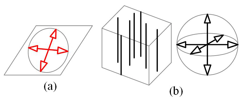
Figure 1(a) Freedom space of the moving platform. (b) Constraint space of the moving platform.
Figure 1a shows that both translation freedoms of the moving platform are on the plane spanned by the moving platform. Figure 1b shows that the three torque constraints on the moving platform intersect at a point in space, and three force constraints are parallel to each other in space, which is equal to a vertical upward force constraint and three torque constraints. Thus, all possible same-dimensional constraint spaces of the moving platform are obtained by keep the constraints unchanged, as shown in Table 2. For example, it is easy to know that the symbols 2, 4, 6, and 7 in Table 2 represent the same-dimensional constraint spaces, and the dimensional is equal to 4. Among them, the dimensional is also equal to 4. The symbols 1, 3, and 5 in Table 2 can be seen to have the same dimensional constraint space.

Step 2: determine the fundamental building block
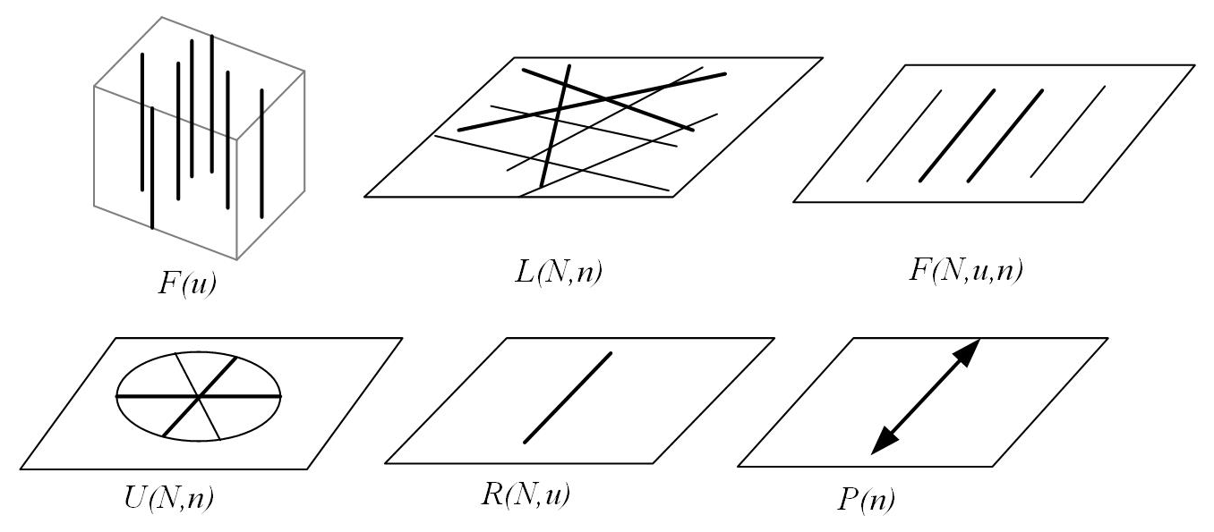
According to proposed synthesis method in the Sect. 2.3, the fundamental building block is obtained. Then, the low-dimensional constraint spaces are obtained in terms of decomposing the CSs obtained from Table 2. Thus, we can generate a complete fundamental building block (FBB) library, which is the low-dimensional constraint spaces. The fundamental building blocks are illustrated in Fig. 2.
Step 3: determine the symmetric constraint spaces
In order to ensure that the mechanism has good bearing capacity and driving characteristics to realize the plane 2T motion, a redundant actuator is adopted. According to the introduced type synthesis process in Sect. 2.3 and the synthesis conditions in Sect. 2.2, the number of the redundant actuator W is determined.
First, according to the principle of symmetry, the symmetry compliant mechanisms with four compliant limbs are determined. Thus, the range of the number of the redundant actuators is obtained, as shown in Eq. (3), as follows:
Then, according to the principle of independent drive, each compliant branch only has one actuator as the active pair. Thus, the range of the number of the redundant actuators is obtained, as shown in Eq. (4), as follows:
Finally, according to the minimum principle of redundant actuated motion pairs, the actuated motion pairs are obtained. That is, W is equal to 2. Then, the symmetry constraint spaces are obtained, as shown in Fig. 3.

Figure 3Symmetrical constraint spaces. (a) The first type. (b) The second type. (c) The third type.
Step 4: determine all possible sub-constraint spaces
In order to synthesize the 2T redundant actuated compliant parallel mechanism, the motion module of the compliant branch is synthesized. According to the proposed synthesis method, the sub-constraint spaces, sub-freedom spaces, and the motion modules are obtained in turn.
First, all possible sub-constraint spaces are obtained by combining appropriate FBBs, i.e., the symmetry constraint spaces. For example, the symmetric constraint space 1 is obtained by combining two R(N,u) and two P(n). The R(N,u) represents the single-force constraint. The P(n) represents the single torque constraint.
Similarly, all symmetrical constraint spaces can obtain by selecting appropriate FBBs. Thus, we obtain six sub-constraint spaces including single-force constraint, single torque constraint, two-force constraints, two torque constraints, one-force constraint and one torque constraint, and three-force constraints, as shown in Fig. 4.
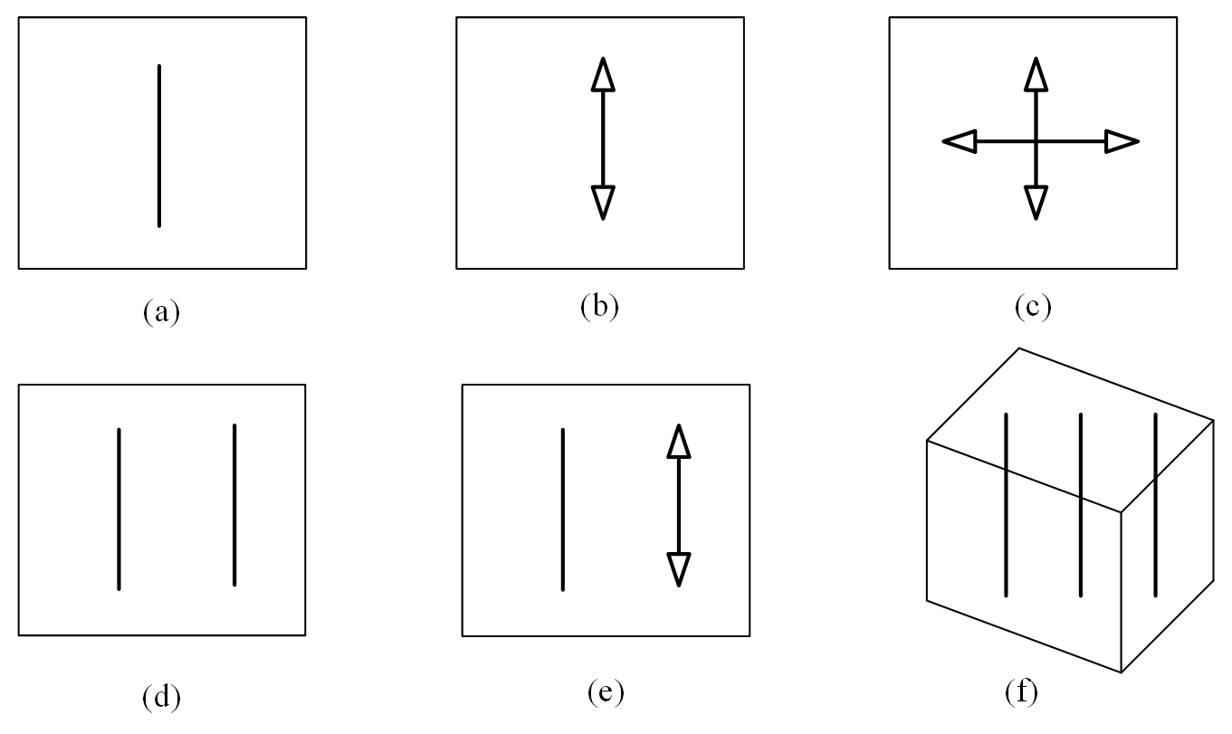
Figure 4All possible sub-constraint spaces. (a) Single-force constraint. (b) Single torque constraint. (c) Two torque constraints. (d) Two-force constraints. (e) One-force constraint and one torque constraint. (f) Three-force constraints.
Step 5: determine motion modules of compliant branch
Taking the single-force constraint as an example, the reciprocal sub-freedom spaces and the motion modules of the compliant branch corresponding to sub-freedom spaces are obtained. For the single-force constraint case, its reciprocal sub-freedom spaces are obtained, as shown in Table 3. The motion modules of the compliant branch are obtained by mapping the geometric module to the motion module. Part of the configurations of the compliant branch under the single-force constraint are shown in Table 4. For convenience, the motion modules are defined as set A. Such modules correspond to a sub-constrained space with a single-force constraint.
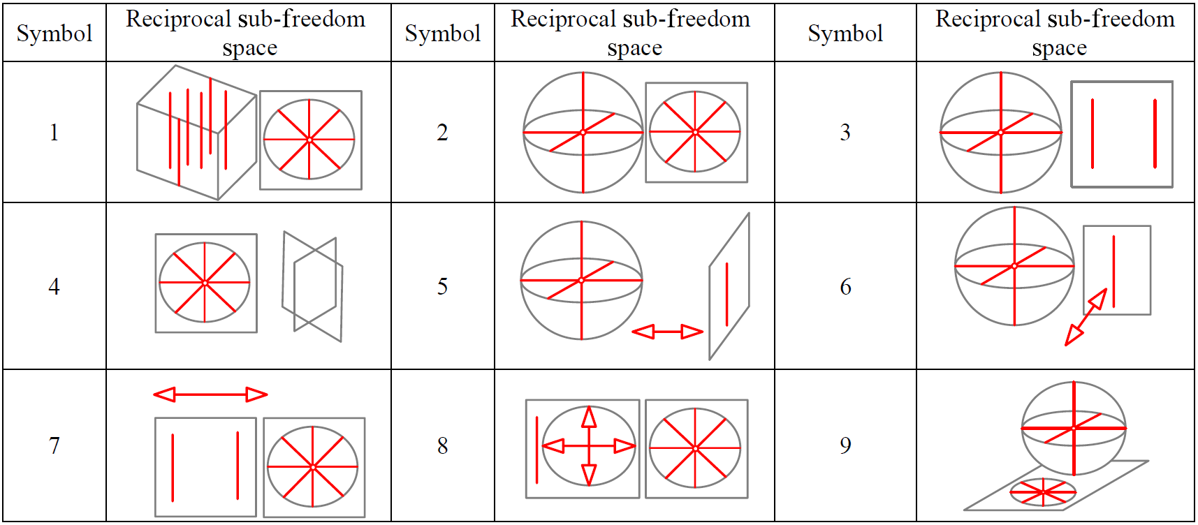
Table 4The configurations of a compliant branch under single-force constraint.
As shown in Table 4, (RRR)s denotes the connection that all hinges connect to, in turn, and intersect at, (RR)s denotes the connection that all hinges connect to, in turn, and intersect at, (PR)c denotes the cylindrical pair formed by the rotating pair and the prismatic pair, RRR denotes that the rotation axes of all hinges intersect at a point, Ri denotes the rotation around the x axis, Rj denotes the rotation around the y axis, Rk denotes the rotation around the y axis, Pi denotes the translation along the x axis, Pj denotes the translation along the y axis, and Pk denotes the translation along the y axis. U denotes the universal joint, and S denotes the spherical pair.
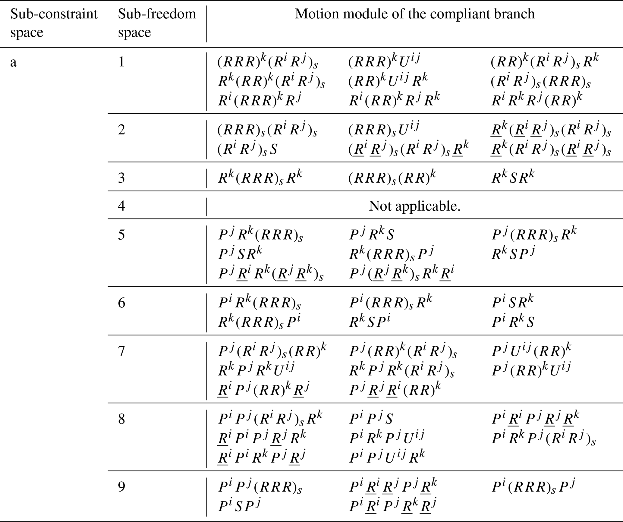
Similarly, the reciprocal sub-freedom spaces are obtained by analyzing the other five kinds of constraints in Fig. 4. Then, its motion modules of the compliant branch corresponding to the sub-constraint spaces are obtained, as shown in Table 5. For example, set B denotes the motion modules of the compliant branch corresponding to the sub-constrained spaces with one torque constraints, set C denotes the motion modules of the compliant branch corresponding to the sub-constrain spaces with two torque constraints, and set D denotes the motion modules of the compliant branch corresponding to the sub-constrained spaces with two-force constraints.
Table 5The motion modules of the compliant branch under the different constraint case.
3.2 Synthesis of the compliant mechanism
Step 6: obtain the motion module of compliant mechanism
In order to obtain the 2T redundant actuated compliant parallel mechanism, the motion modules of the compliant mechanism are synthesized. According to the proposed synthesis method, the number and the layout of compliant branches are determined, respectively. Then, the motion modules of compliant mechanism are obtained through the parallel arrangement.
According to results in the Sect. 3.1, the DOF, M, and the number of the redundant actuators W are determined, respectively. And, the number of compliant branches n can be calculated via Eq. (1). In this paper, the M is equal to 2, the W is equal to 2, and n is equal to 4.
Based on proposed synthesis method, suitable sub-constraint spaces are selected. Then, the value of the rank of the constraint spaces is determined, and the combination scheme requirements are judged by the Eq. (2). According to Fig. 4, the rank of all constraint spaces is easily obtained. For the single-force constraint space, dim(Ca) is equal to 1. For the single torque constraint, dim(Cb) is equal to 1. For two torque constraints, dim(Cc) is equal to 2. For two-force constraints, dim(Cd) is equal to 2. For one-force and one torque constraints, dim(Ce) is equal to 2. For three-force constraints, dim(Cf) is equal to 3.
As we can see, there are five kinds of combination schemes with ideal constraint in Table 6. For the first scheme, as an example, the mechanism is constrained by four branch chains, and two of them simultaneously provide two-force constraints. The rests provide two torque constraints, for which two rotations in the plane and out of the plane are constrained, respectively. Thus, the relationship of the rank is obtained and can be written as follows:
where dim(Cd) denotes the rank of the two-force constraints, dim(Cc) denotes the rank of the two torque constraints, and dim(Cm) denotes the rank of the mechanism. Thus, scheme one is satisfactory. Scheme one is determined as being a one-combination scheme.
According to the synthesis results in Sect. 3.1, this paper has obtained motion modules of a compliant branch corresponding to each sub-constraint by the proposed synthesis method, respectively. For the first scheme, as an example, the elements of sets C and D are selected, and the motion modules of the mechanism is obtained. Part of the motion modules of the mechanism are shown in Table 7.
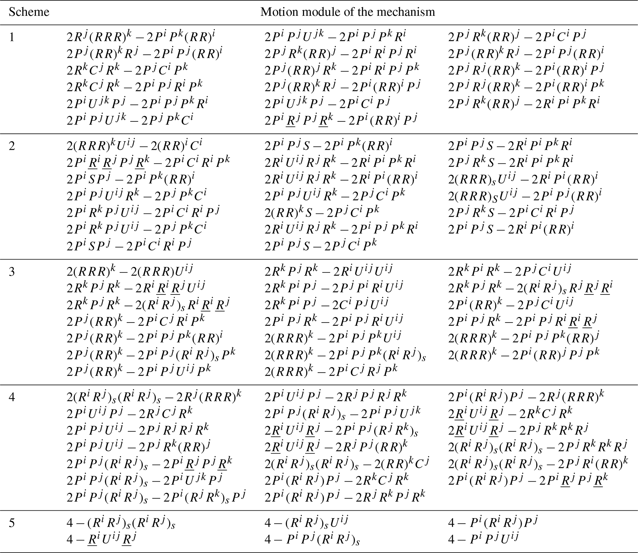
Similarly, the constraints of each compliant branch are determined by analyzing other schemes. Thus, the elements are selected from the different sets. Those elements are combined. Then, the motion modules of the mechanism are obtained corresponding to each combination scheme, and part of the motion modules of the mechanism are also shown in Table 7.
Step 7: determine the compliant parallel mechanisms
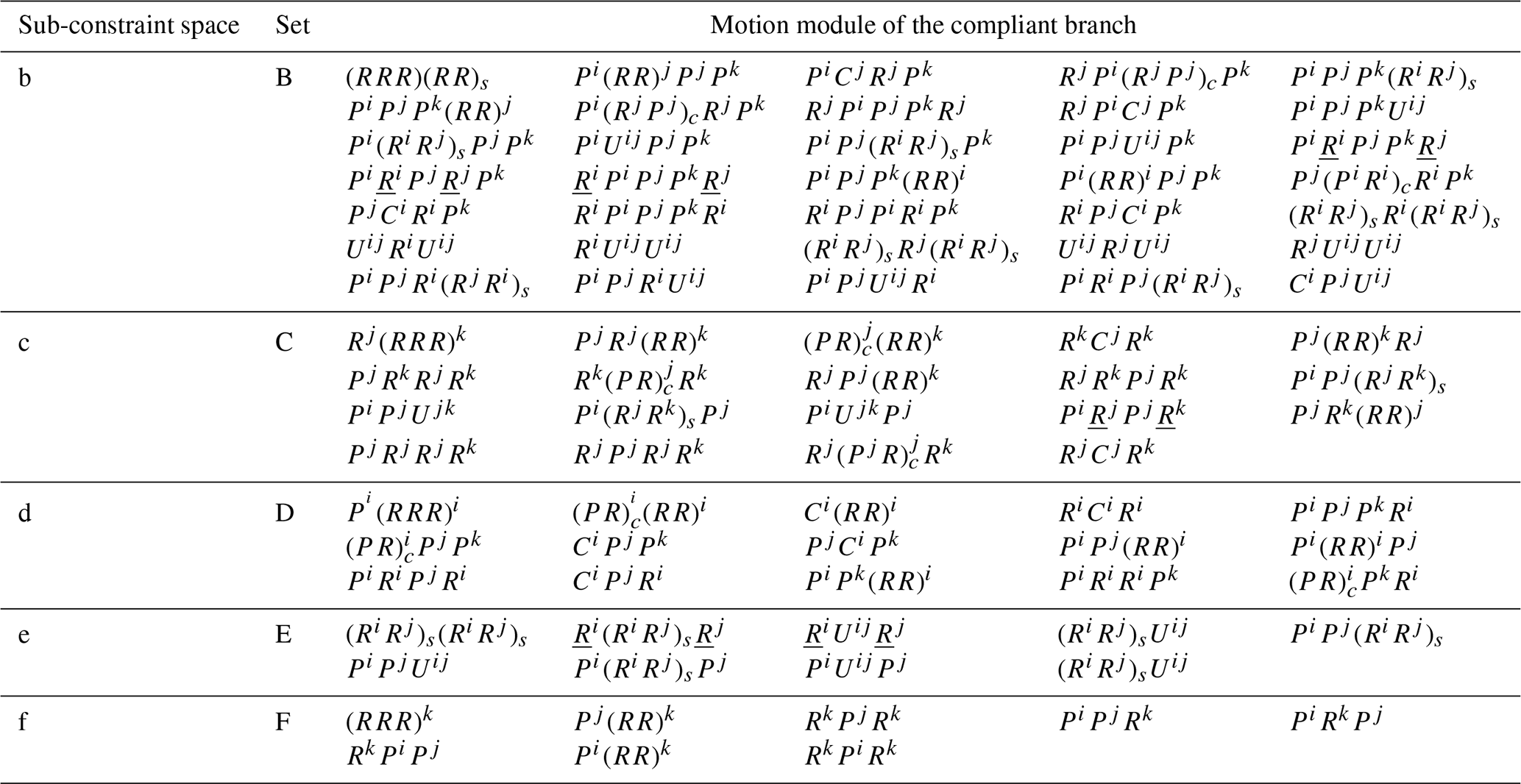
Based on the proposed synthesis method, appropriate flexure hinges are selected. The flexure hinges replace the physical element to achieve the mapping between the motion module and the mechanical module. At last, the 2T redundant actuated compliant parallel mechanisms are obtained.
In this paper, the flexible plate unit is selected as the base unit. And, several typical flexure hinges are shown in Table 8. These flexure hinges are combined with the flexible plate unit. P denotes the prismatic joint, R denotes the rotating joint, U denotes the universal joint, the S denotes the spherical joint. For 4-PPS, as an example, two prismatic joints and one spherical joint are selected to replace the corresponding two physical elements. Through the different arrangement, the two prismatic flexure pair can achieve the required motion. And the new compliant parallel mechanism is determined.
According to the proposed motion modules of the compliant mechanism in Sect. 3.2, these flexure hinges are selected to replace the those corresponding to the physical elements, and the new redundant actuated compliant parallel mechanisms are obtained. Parts of the compliant branches are shown in Fig. 5, and parts of the compliant parallel mechanisms are shown in Fig. 6.
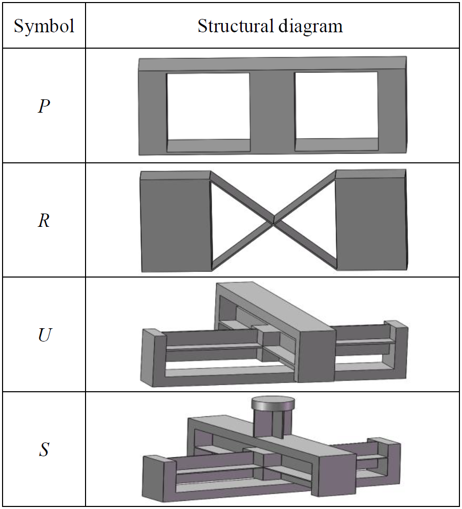
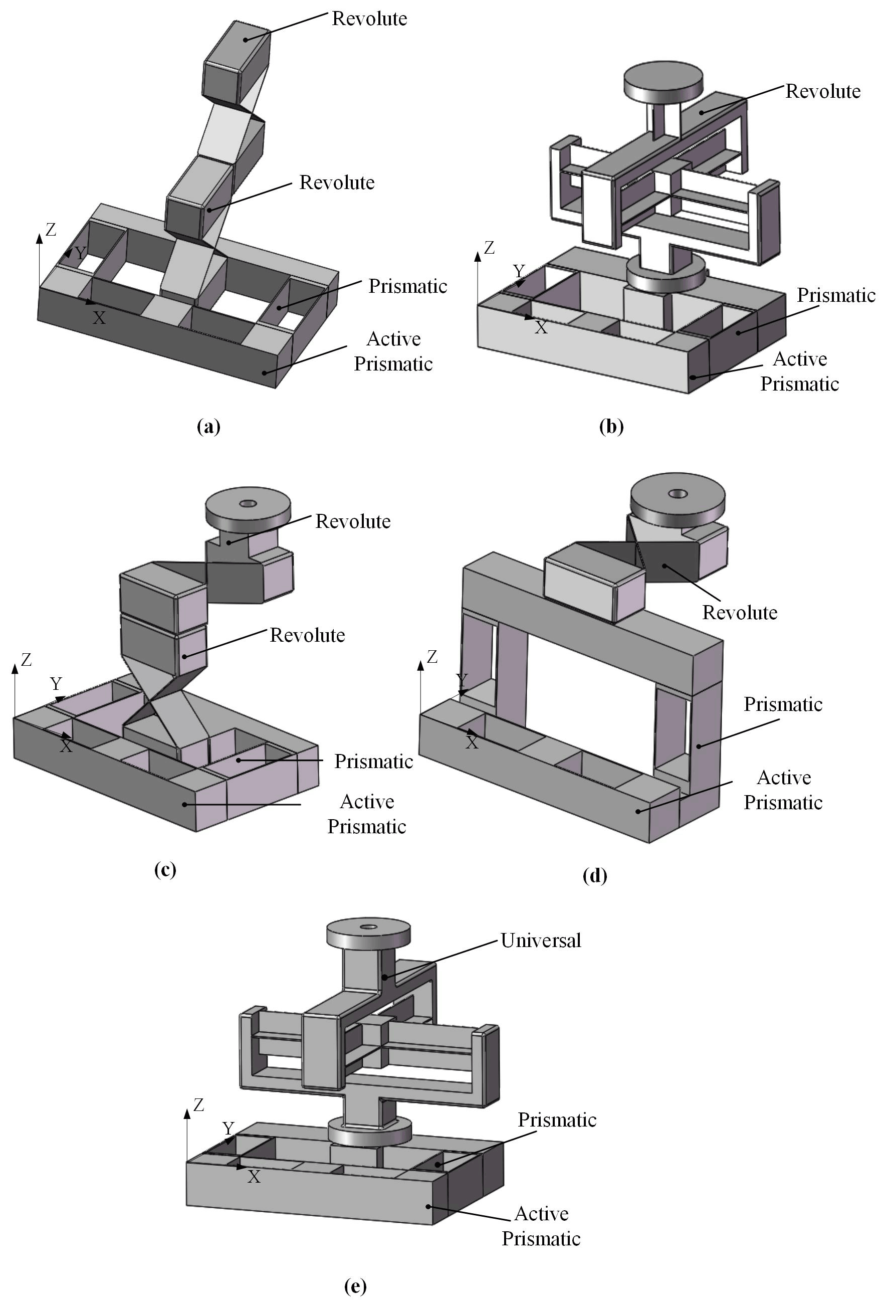
Figure 5(a) PjPi(RR)i compliant branch. (b) PjPiS compliant branch. (c) PjPiRjRk compliant branch. (d) PjPiRk compliant branch. (e) PiPjUij compliant branch.
In Fig. 5, the kind and the arrangement of the flexure hinges are obtained by observing each compliant branch. As shown in Fig. 5a, the PjPi(RR)i compliant branch has one prismatic joint along the x axis, one prismatic joint along the y axis, and two revolute joints that rotate about the x axis. As shown in Fig. 5b, the PjPiS compliant branch has one prismatic joint along the x axis, one prismatic joint along the y axis, and one spherical joint. Besides, these flexure hinge connect in turn. As shown in Fig. 5c–e, the kind and the arrangement of the flexure hinge are also determined for the other three compliant branches. They all also have one prismatic joint along the x axis and one prismatic joint along the y axis.
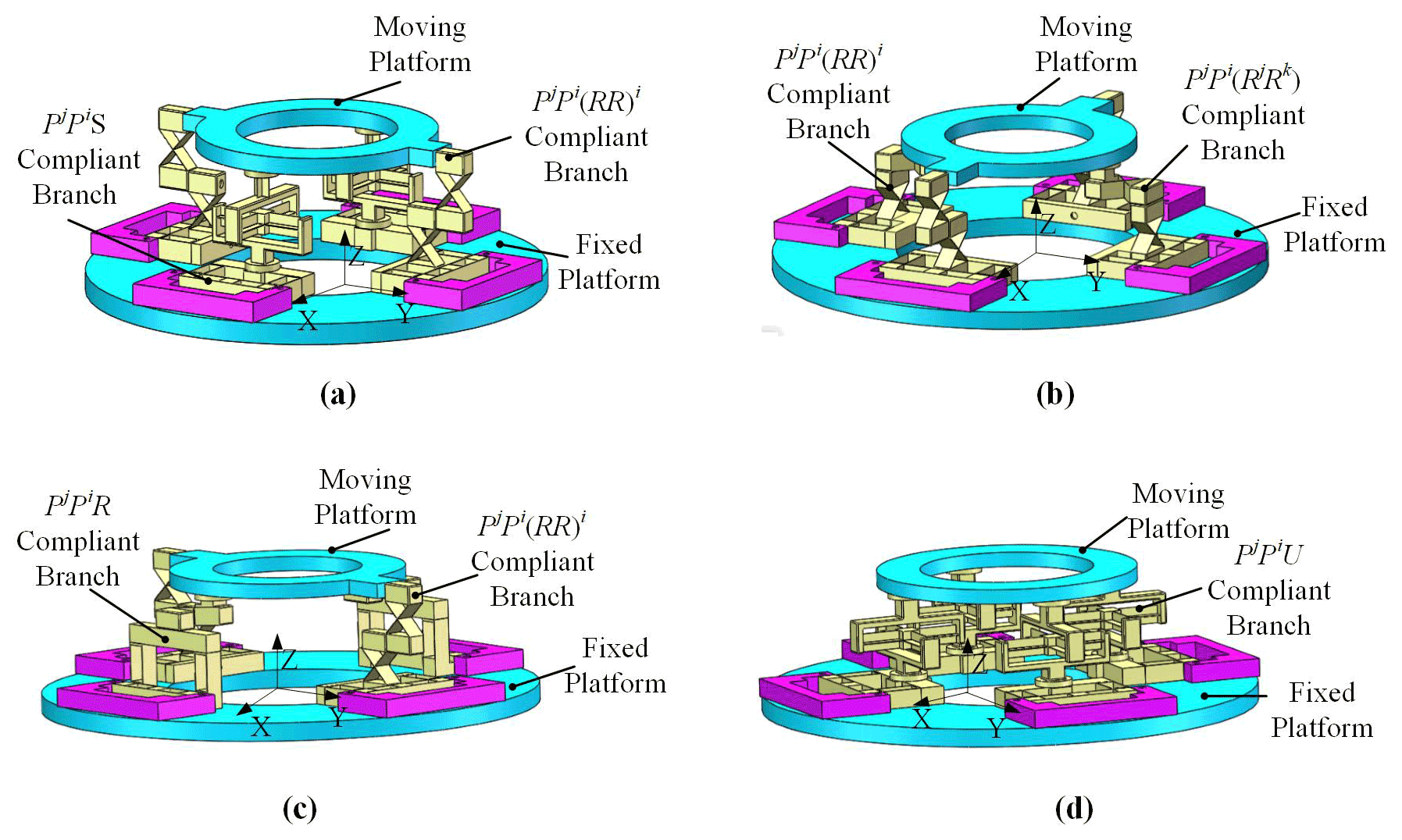
Figure 6(a) 2PjPi(RR)i−2PjPiS compliant parallel mechanism. (b) 2PjPi(RR)i−2PjPiRjRk compliant parallel mechanism. (c) 2PjPi(RR)i−2PjPiRk compliant parallel mechanism. (d) 4−PiPjUij compliant parallel mechanism.
In Fig. 6, four kinds of CPMs are demonstrated. Among them, each mechanism has four compliant branches, and each compliant branch has a prismatic joint as the driving joint. As shown in Fig. 6a, the 2PjPi(RR)i−2PjPiS compliant parallel mechanism is a plane symmetrical CPM. The Pj is the driving joint in the PjPi(RR)i compliant branch. The Pj is also the driving joint in the PjPiS compliant branch. Figure 6b shows that the 2PjPi(RR)i−2PjPiRjRk compliant parallel mechanism is also the plane symmetrical CPM. Figure 6c shows that the 2PjPiRk−2PjPi(RR)iRj compliant parallel mechanism is also the plane symmetrical CPM. In addition, as shown in Fig. 6d, the 4−PiPjUij compliant parallel mechanism is the whole symmetrical CPM. The mechanism has a small parasitic motion to achieve a high-precision motion.
Step 8: DOF analysis of the mechanism
In order to verify the correctness of the proposed synthesis method, the synthesized mechanism is analyzed. In this section, taking the 4−PiPjUij compliant parallel mechanism as an example, the atlas method is carried out to validate the DOF of the mechanism.
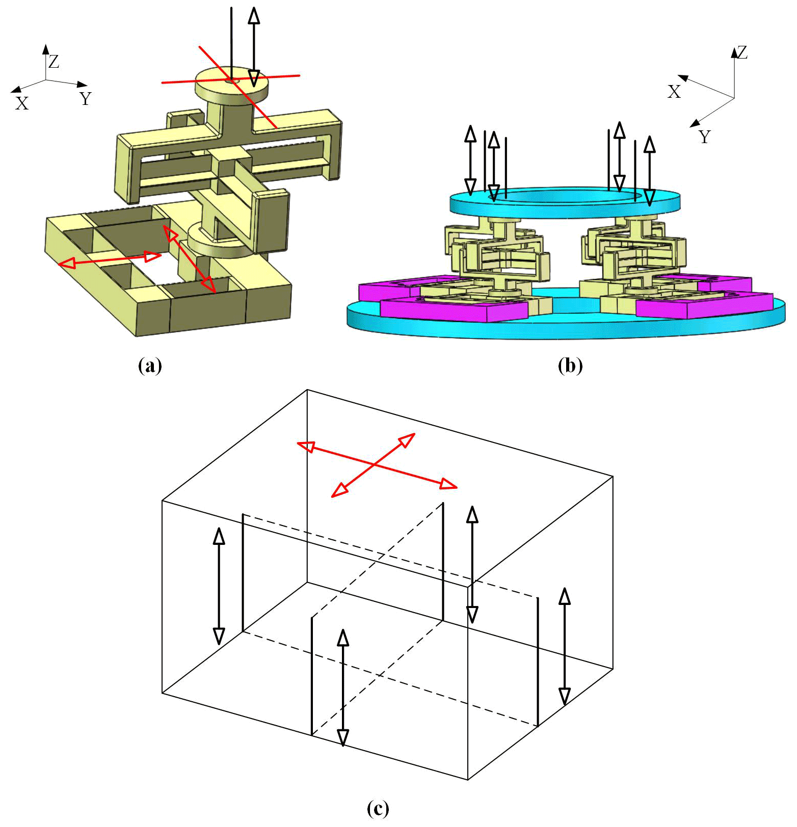
Figure 7(a) The freedom lines and the constraint lines of the PiPjUij compliant branch. (b) The constraint lines of the 4−PiPjUij redundant actuated compliant parallel mechanism. (c) The freedom lines and the constraint lines of the 4−PiPjUij redundant actuated compliant parallel mechanism.
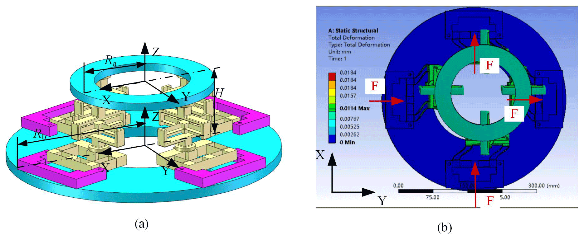
Figure 8(a) The 4−PiPjUij compliant parallel mechanism. (b) The deformation distribution of the 4−PiPjUij CPM.
First, the freedom space and the constraint space of the compliant branches are obtained. Then, the constraint space of the mechanism is obtained based on the constraints of the compliant branches. Finally, the freedom space of the mechanism is obtained by the Blanding rule. The structure diagram is obtained for the 4−PiPjUij compliant parallel mechanism, and its lines graphs are determined, as shown in Fig. 7.
According to the type of flexure hinges and the geometric characteristics of the mechanism, we know that the mechanism belongs to the small deformation case, assuming that the pose of the mechanism always remains unchanged. As shown in Fig. 7a, each compliant branch provides a force constraint and a torque constraint on the moving platform during the motion of the mechanism. And, those constraints are always vertical to the moving platform. Figure 7b shows that the moving platforms of the compliant mechanism are constrained by four same-force constraints and the four same-torque constraints. A paired parallel force constraint of these is equivalent to one originated force constraint. And, the one torque constraint is perpendicular to the plane in which this pair parallel force constraint is determined. As shown in Fig. 7c, the three-dimensional rotation is constrained, and the translation motion is also constrained in the vertical direction (z direction). Thus, the moving platform can achieve the translation motion in the x and y directions. It is proved that the 4−PiPjUij mechanism can achieve two translational motions.
3.3 Finite element analysis
In this section, taking the 4−PiPjUij CPM as an example, the finite element simulation is carried out to analyze the motion characteristic of the 4−PiPjUij CPM. For the finite element model of the 4−PiPjUij CPM, the material is aluminum alloy with low density and high strength. The material properties are identified, where the Young's modulus E is 71 GPa, Poisson's ratio μ is 0.33, and the density ρ is 2810 kg/m3. In Fig. 8, the structure of the 4−PiPjUij CPM and the deformation distribution of the 4−PiPjUij CPM are shown, respectively.
As shown in Fig. 8a, let the circumradius of the moving platform, Ra, be 105 mm, the circumradius of the fixed platform, Rb, be 200 mm, and the height of the moving platform and the fixed platform, H, be 105 mm. As shown in Fig. 8b, the mechanism has four actuators. When four actuators apply 5 N of force at the same time, the deformation distribution of the mechanism is obtained. The result shows that the moving platform translations along the y axis and x axis. Therefore, the 4−PiPjUij CPM can realize the XY translation.
In this paper, a new synthesis method is introduced for a 2T redundant actuated compliant parallel mechanism. The new method is a systematic and simple synthesis method. The whole type synthesis principle is built upon the FACT approach, also combining with other principles, including the principle of independent driving and the symmetrical principle. The criteria are introduced for the type synthesis of the redundant actuated compliant parallel mechanism, and the process of type synthesis is described in detail. For this new method, the feasibility and rationality are verified by analyzing the DOF of the mechanism. New 2T redundant actuated compliant parallel mechanisms are proposed. The synthesized mechanisms have some merit, e.g., high carrying capacity, high motion or force transfer performance, and good driving stability. It can be utilized for micro- or nano-positioning applications, e.g., biomedical engineering, (integrated circuit) IC packages, scanning probe microscopy, fiber optics alignments, micro-assembly, and nano-imprint lithography.
All the data used in this paper can be obtained on request from the corresponding author.
SL and YZ conceived the presented idea. YZ established an overall paper research framework and the model. YS and SC assisted with the theory. JH assisted with FEM. All the authors read and approved the final paper.
The contact author has declared that neither they nor their co-authors have any competing interests.
Publisher's note: Copernicus Publications remains neutral with regard to jurisdictional claims in published maps and institutional affiliations.
We would like to thank the NSFC (grant no. 51775475) and the Military and Civilian Integration Project of Hebei Province (grant no. 2020B030) for the financial support.
This research has been supported by the National Natural Science Foundation of China (grant no. 51775475) and the Military and Civilian Integration Project of Hebei Province (grant no. 2020B030).
This paper was edited by Daniel Condurache and reviewed by three anonymous referees.
Awtar, S. and Slocum, A. H.: Constraint-based design of parallel kinematic XY flexure mechanisms, J. Mech. Design, 129, 816–830, https://doi.org/10.1115/1.2735342, 2007.
Blanding, D. L.: Exact constraint: machine design using kinematic principles, ASME Press, New York, 1999.
Choi, K. B., Lee, J. J., Kim, G. H., and Lim, H. J.: XY parallel compliant stage with compact configuration, J. Nanosci. Nanotechno., 12, 5245–5251, https://doi.org/10.1166/jnn.2012.6262, 2012.
Clark, L., Shirinzadeh, B., Tian, Y., and Yao, B.: Development of a passive compliant mechanism for measurement of micro/nanoscale planar 3-DOF motions, IEEE-ASME. T. Mech., 21, 1222–1232, https://doi.org/10.1109/TMECH.2015.2503728, 2016.
Deng, J., Liu, Y. X., Chen, W. S., and Yu, H. P.: A XY transporting and nanopositioning piezoelectric robot operated by leg rowing mechanism, IEEE ASME. T. Mech, 24, 207–217, https://doi.org/10.1109/TMECH.2019.2890825, 2019.
Dong, S. Z., Guo, K., Li, X. L., Chen, H. N., and Ni, M. Y.: Design and analysis of adjustment mechanism with slit diaphragm flexures for optical element, Chin. Opt. Lett., 10, 790–797, https://doi.org/10.3788/co.20171006.0790, 2017.
Du, Y. S. and Li, T. M.: Output decoupling modeling of a XY flexure-based compliant manipulator, J. Mech. Sci. Technol., 34, 269–277, https://doi.org/10.1007/s12206-019-1228-7, 2020.
Fan, C. H.: Research on optimizing design method and experiment of fully compliant mechanism, MS thesis, Beijing: North China University of Technology, China, 88 pp., 2006.
Hao, G. B.: A 2-legged XY parallel flexure motion stage with minimised parasitic rotation, Proc. IME. C. J. Mech. Eng. Sci., 228, 3156–3369, https://doi.org/10.1177/0954406214526865, 2014.
Hao, G. B.: A multi-axis, large-output, sensing framework of integrating linear optical encoders for nanopositioning systems, IEEE. Sens. Lett., 1, 1–4, https://doi.org/10.1109/LSENS.2017.2697074, 2017.
Hao, G. B. and Kong, X. W.: A novel large-range XY compliant parallel manipulator with enhanced out-of-plane stiffness, J. Mech. Design, 134, 1–10, https://doi.org/10.1115/1.4006653, 2012.
Hao, G. B. and Yu, J. J.: Design, modelling and analysis of a completely-decoupled XY compliant parallel manipulator, Mech. Mach. Theory., 102, 179–195, https://doi.org/10.1016/j.mechmachtheory.2016.04.006, 2016.
He, G. P. and Zhen, L.: The research on the redundant actuated parallel robot with full compliant mechanism, in: First International Conference on Integration and Commercialization of Micro and Nanosystems, 10–13 January 2007, Sanya, China, 2007.
Hopkins, J. B. and Culpepper, M. L.: Synthesis of multi-degree of freedom, parallel flexure system concepts via freedom and constraint topology (FACT) – Part I: Principles, Precis. Eng., 34, 259–270, https://doi.org/10.1016/j.precisioneng.2009.06.008, 2010a.
Hopkins, J. B. and Culpepper, M. L.: Synthesis of multi-degree of freedom, parallel flexure system concepts via freedom and constraint topology (FACT) – Part I: Principles, Precis. Eng., 34, 271–278, https://doi.org/10.1016/j.precisioneng.2009.06.007, 2010b.
Kittinanthapanya, R., Sugahara, Y., Matsuura, D., and Takeda, Y.: Development of a novel SMA-driven compliant rotary actuator based on a double helical structure, Robotica, 8, 1–18, https://doi.org/10.3390/robotics8010012, 2019.
Lai, L. J. and Zhu, Z. N.: Design, modeling and testing of a novel flexure-based displacement amplification mechanism, Sensor Actuat. A-Phys., 266, 122–129, https://doi.org/10.1016/j.sna.2017.09.010, 2017.
Liu, H., Fan, S. X., Xie, X., Zhang, Z. Y., and Fan, D. P.: Design and modeling of a novel monolithic parallel XY stage with centimeters travel range, Adv. Mech. Eng., 9, 1–17, https://doi.org/10.1177/1687814017729624, 2017.
Liu, Y. J. and Zhang, Z.: A large range compliant XY nano-manipulator with active parasitic rotation rejection, Precis. Eng., 72, 640–652, https://doi.org/10.1016/j.precisioneng.2021.07.008, 2021.
Gräser, P., Lin, S., Harfensteller, F., Torres, M., Zentner, L., and Theska, R.: High-precision and large-stroke XY micropositioning stage based on serially arranged compliant mechanisms with flexure hinges, Precis. Eng., 72, 1–10, https://doi.org/10.1016/j.precisioneng.2021.02.001, 2021.
Mahl, T., Hildebrandt, A., and Sawodny, O.: Forward kinematics of a compliant pneumatically actuated redundant manipulator, 7th IEEE Conference on Industrial Electronics and Applications (ICIEA), 18–20 July 2012, Singapore, 2012.
Qi, H. M., Chen, Y. C., Zhang, N., Zhang, B. J., Wang, D., and Tan, B. H.: Improvement of both handling stability and ride comfort of a vehicle via coupled hydraulically interconnected suspension and electronic controlled air spring, P. I. Mech. Eng. D-J. Aut., 234, 1–20, https://doi.org/10.1177/0954407019856538, 2019a.
Qi, H. M., Zhang, B. J., Zhang, N., Zheng, M. Y., and Chen, Y. C.: Enhanced lateral and roll stability study for a two-axle bus via hydraulically interconnected suspension tuning, Sae. Int. J. Veh. Dyn. St., 3, 1–13, https://doi.org/10.4271/10-03-01-0001, 2019b.
Qi, H. M., Zhang, N., Chen, Y. C., and Tan, B. H.: A comprehensive tune of coupled roll and lateral dynamics and parameter sensitivity study for a vehicle fitted with hydraulically interconnected suspension system, P. I. Mech. Eng. D-J. Aut., 235, 1–19, https://doi.org/10.1177/0954407020944287, 2020.
Qin, Y. D., Shirinzadeh, B. J., Tian, Y. L., and Zhang, D. W.: Design issues in a decoupled XY stage: static and dynamics modeling, hysteresis compensation, and tracking control, Sensor. Actuat. A-Phys., 194, 95–105, https://doi.org/10.1016/j.sna.2013.02.003, 2013.
Tagliamonte, N. L., Sergi, F., Accoto, D., Carpino, G., and Guglielmelli, E.: Double actuation architectures for rendering variable impedance in compliant robots: a review, Mechatronics, 22, 1187–1203, https://doi.org/10.1016/j.mechatronics.2012.09.011, 2012.
Tan, B. H., Wu, Y., Zhang, N., Zhang, B. J., and Chen, Y. C.: Improvement of ride quality for patient lying in ambulance with a new hydro-pneumatic suspension, Adv. Mech. Eng., 11, 1–20, https://doi.org/10.1177/1687814019837804, 2019.
Tian, Y. L., Liu, C. F., Liu, X. P., Wang, F. J., Li, X. C., Qin, Y. D., Zhang, D. W., and Shirinzadeh, B. J.: Design, modelling and characterization of a 2-DOF precision positioning platform, Trans. Inst. Meas. Contr., 37, 396–405, https://doi.org/10.1177/0142331214540692, 2014.
Wan, S. C. and Xu, Q. S.: Design of a new compliant XY micro-positioning stage based on Roberts mechanism, Mech. Mach. Theory., 95, 125–139, https://doi.org/10.1016/j.mechmachtheory.2015.09.003, 2016.
Wang, M., Zhang, B. J., Chen, Y. C., Zhang, N., Chen, S. Z., and Zhang, J.: Frequency-based modeling of a vehicle fitted with roll-plane hydraulically interconnected suspension for ride comfort and experimental validation, IEEE Access., 8, 1091–1104, https://doi.org/10.1109/ACCESS.2019.2935260, 2020.
Xu, Q.: Design and development of a compact flexure-based XY precision positioning system with centimeter range, IEEE Trans. Ind. Electron., 61, 893–903, https://doi.org/10.1109/TIE.2013.2257139, 2013.
Yang, M., Zhang, C., Yu, H. T., Huang, X. L., Yang, G. L., and Fang, Z. J.: Kinetostatic modeling of redundantly actuated planar compliant parallel mechanism, 12th International Conference on Intelligent Robotics and Applications(ICIRA), 8–11 August 2019, Shenyang, China, 2019.
Yun, Y. and Li, Y. M.: Optimal design of a 3-PUPU parallel robot with compliant hinges for micromanipulation in a cubic workspace, Robot. Cim.-Int. Manuf., 27, 977–985, https://doi.org/10.1016/j.rcim.2011.05.001, 2011.
Zhang, D. F. and Zhao, L.: Research of monolithic XY micro-adjustment mechanism based on compliance matrix, Chin. J. Sci. Instrum., 35, 269–275, https://doi.org/10.19650/j.cnki.cjsi.2014.02.005, 2014.
Zhang, X. Z., Zhang, Y. L., and Xu, Q. S.: Design and control of a novel piezo-driven XY parallel nanopositioning stage, Microsyst. Technol., 23, 1067–1080, https://doi.org/10.1007/s00542-016-2854-y, 2017.