the Creative Commons Attribution 4.0 License.
the Creative Commons Attribution 4.0 License.
 | 26 Oct 2021
Research on a cascade model synthesis with the use of classical and non-classical methods in the context of new piezoelectric stack applications
Jacek Harazin
Andrzej Wróbel
Active audio noise cancellation technology using piezoelements is fairly new and emerging technology on the market in recent years and is still gaining in popularity. The ability to use piezoelectric devices to gather information about vibration spectrum and to create interfering waves, to cancel out the noise, allows for the reduction in passive vibration methods and gives more flexibility in terms of space and application. The idea of using this technique on larger scales such as industrial equipment is the focus of ongoing research conducted by the authors of this article. This work is intended as the first part of a larger project and focuses solely on theoretical approach to the problem of modelling mechatronic systems capable of creating complex vibration spectrums and using piezoelectric components. The authors have focused on creating a mix of classical and non-classical methods to synthesize model systems based on input resonance frequencies. A classical calculation through matrix equations was also done to validate the accuracy of obtained results through the structural number method. The resulting model is still awaiting the empirical verification through extensive testing on real-life models, and that part of the research is still being developed. When validated and checked, this technology could bring new solutions in the vibration damping of industrial equipment, potentially increasing its flexibility and effectiveness.
- Article
(1331 KB) - Full-text XML
- BibTeX
- EndNote


Machine vibrations are a normal and typically unavoidable result of imperfections in moving and rotating parts and their interactions with different environments and mediums. Coupling imperfections, misalignments, mass imbalance and assembly tolerances can all become a source of unwanted vibrations (Lyon, 1987; Tavner, 2008; Salokyova et al., 2016). Additionally, in case of equipment that interact with different media like air or fluids with different viscosities, an additional set of disturbance caused by turbulence can introduce vibrations to the system (Mohanta et al., 2017). Over time, those vibrations can increase in amplitude and strength due to parts wearing down and imperfections accumulating in the system. Deteriorating stability can eventually lead to structural damage and generate costly repairs. Unwanted vibrations can negatively impact any devices or humans that operate in their proximity and propagate through the structure of buildings (Shrestha, 2018; Bergamo et al., 2020; Du et al., 2020). Devices such as controllers and optical or mechanical sensors can be very sensitive to background noise in form of mechanical vibrations and usually require some form of filtration or damping. In case of humans, vibrations can also be very harmful with long and frequent exposure (Hagood and Flotow, 2003). To prevent unwanted vibrations, various types of passive and active damping methods were developed (Kowal et al., 1995; Rivin, 2001; Benjeddou and Ranger, 2006; Brownjohn and Pavic, 2006; Kozek et al., 2011).
Passive vibration damping methods focus on dissipation or reduction of vibrations through various technological means and can be further divided into the following subgroups:
-
elimination of vibration sources,
-
elimination of vibrations during propagation, and
-
dissipation of vibration energy.
Vibrations can be reduced through the elimination of vibration sources. The first stage of the elimination process consists of proper part selection and precise fitting during the machine design and construction process. The second stage can be implemented in finished products by proper selection of operating parameters and an active reduction of clearances during inspections. This method of vibration reduction is, however, limited to technological design limitations and material properties. Another method of reducing vibrations involves coating the machine or sensor exteriors with insulation surfaces that absorb any incoming or outgoing vibrations with their material structure. This method is effective at reducing high-frequency vibrations but does not do particularly well with low-frequency ones. Last, vibrations of a specific machine can be dampened by cushioning pads or other elements, placed in mounting points, that either dissipate vibrations or isolate vibrating surfaces from exterior (Hagood and Flotow, 2003; Benjeddou and Ranger, 2006). The above-mentioned methods are characterized by only absorbing the energy of a system.
Active vibration-damping methods bring an additional source of energy to specifically counteract vibrations of a system. The active effect can be achieved either through adjusting the damping factor by strengthening magnetic or electric fields (e.g. electro- and magnetorheological dampeners; Dassisti et al., 2021) or by creating an interfering vibration patterns that cancel each other out (e.g. piezoelectric-based vibration dampeners; Kozek et al., 2011). The advantage of active damping systems over passive systems is their capability to damp vibrations with a broader spectrum of frequencies. Another advantage is an ability to dynamically adjust the spectrum to better reduce dynamically changing vibration frequencies.
Piezoelectric materials are a large group of intelligent materials capable of direct energy transfer between electrical and mechanical systems thanks to simple and inverse piezoelectric effects (Soluch et al., 1980; Adriaens et al., 2000). Common use cases for piezoelectric materials include using them in the role of transceivers, converters, sensors and active parts in technologies focusing on audio equipment. The simple piezoelectric effect allows for the transfer of mechanical energy of the crystal deformation into an electric potential, while the inverse effect allows for conversion of an electric potential back into mechanical strain exerted by the material. The ability to convert mechanical and electrical energy comes from a specific asymmetrical crystal structure that creates an uneven distribution of positive and negative charges throughout the piezoelectric element. This project in general focuses on active damping methods that use the inverse piezoelectric effect to create interfering waves that cancel out incoming vibrations. The inverse piezoelectric effect allows for rapid changes in the dimensions of piezoelectric elements by applying alternating current of high frequency. The resulting displacement on a surface of piezoelectric plates or foils can be utilized to counteract incoming vibrations. An example of this method can be seen in active noise cancellation systems installed in headphones (Vijay et al., 1995). The rapid displacement of piezoelectric surface is propagated through a medium of air, resulting in wave interference between incoming noise and vibrations generated by piezoelectric foil. Significant noise reduction can be achieved by applying such a solution which has been proven in recent headphone models that provide this feature (https://www.techradar.com/news/audio/portable-audio/best-noise-cancelling-headphones-1280490, last access: 7 October 2021). However, one of the disadvantages of piezoelectric materials is their small displacement, generated only by the slight change in crystal lattice, making them ineffective against vibrations of higher amplitudes. This downside can be partly mitigated by introducing uniform crystal piezoelectrics or piezo bimorph and stack systems. While piezoelectric crystals obtain bigger displacements due to uniform crystal structure, they are more expensive to produce. An alternative solution involves using multiple plates connected on the axis of elongation to form a piezoelectric stack that achieves greater displacements at the cost of thickness. Such a bimorph or a stack is typically constructed from several piezoelectric plates with very similar or identical shapes and material properties.
The main concept of this whole project is to find ways of enhancing the capability of piezo stacks by incorporating piezoelectric plates of different sizes and material properties and using separate control circuits for each plate to form a complex pattern of vibrations. This concept could enhance the capabilities of piezo stacks by adding an option to generate a broader spectrum of vibrations with more distinct resonant frequencies while still retaining part of the benefits of a normal bimorph or a stack. To make this method viable, a proper mathematical model must be created to give the ability of determining the properties and sizes of piezoelectric plates included in the piezo stack. This article in particular has been devoted to the theoretical part of finding possible ways of synthesizing a mathematical model to reflect the real work of a piezoelectric stack. To achieve this, several classical and non-classical methods of developing a model have been studied (Wojnarowski, 1977; Soluch et al., 1980; Wojnarowski, 1981; Goldfarb and Celanovic, 1997; Buchacz et al., 1997, 1999; Bellert and Woźniacki, 2000; Buchacz and Żurek, 2005; Białas et al., 2009; Buchacz and Wróbel, 2010; Wang and Tsai, 2011; Białas, 2012; Białas and Buchacz, 2014; Wróbel, 2018). The choice was made to use a combination of classical methods such as polynomial chain fractioning and graphs/structural number algebra to determine the parameters of a working model. A piezo stack can be considered as a cascade system, where each plate is a separate element with its own set of properties represented by basic physical objects like masses, springs and dampers. The resulting outcome of entire system is a sum of dependencies between all such elements. There are classical methods of calculating outputs of such model through matrix equations that combine all inputs and are used to devise equations for calculating the desired set of outputs. The calculations can become very complicated with an increasing number of interacting elements inside the system and are typically hard to implement into machine calculation. This article will investigate the accuracy and complexity of such calculations through the non-classical method of using graphs and structural numbers in context of a cascade system being developed to simulate the work of a piezoelectric stack. An example of a 2 degrees of freedom system is used to illustrate the process of synthesizing the model through the use of polynomial chain fractioning. After the process of model synthesis, a short description of the graph and structural number method is made to show the complexity of this method. A comparison of results obtained through matrix equations is made to show the accuracy of the obtained results.
A cascade model is a type of mechanical or electrical model in which all the moving elements (or current loops) are connected in series with each other. The effect of such a connection causes the displacements (or voltages in the voltage analogy of electrical systems) to be affected only by the neighbouring elements (which, in turn, are also affected by their neighbours). Such a chain of interactions can be portrayed as a cascade of effects, hence the name of the model. A graphical representation of a simple, 2 degrees of freedom, mechanical cascade model can be seen in Fig. 1. Another representation of a different, simple electrical model can be seen in Fig. 2.
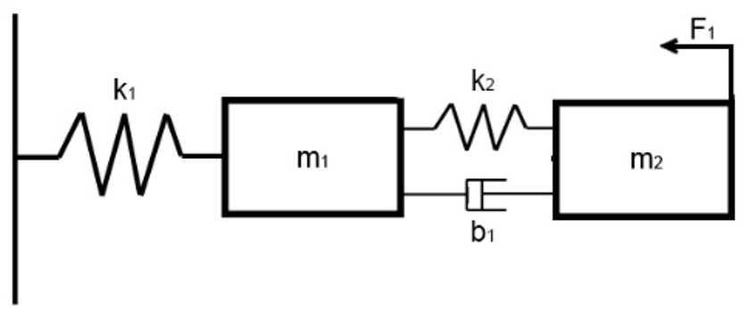
Figure 1Example of a 2 degrees of freedom mechanical cascade model. Masses are denoted by mi, springs by ki, dampers by bi and external forces by Fi.
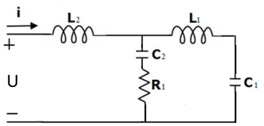
Figure 2Example of a 2 degrees of freedom electrical cascade model created in the voltage analogy to mechanical model. Masses are represented by coils Li, springs are the capacitors Ci and dampers are the resistors Ri. The external forces are represented by voltages Ui.
A decision was made to use the chain fractioning method (Buchacz and Żurek, 2005; Białas et al., 2009; Buchacz and Wróbel, 2010) in attempt to create the first cascade model because of its simplicity in the derivation of parameters from the input dynamic characteristic. There are four different possible types of cascade systems that can be determined, depending on the type of system excitation (dynamic or kinematic) and the type of restraint (restrained or non-restrained system; Buchacz et al., 1999; Białas, 2012; Białas and Buchacz, 2014). To better illustrate the process of model synthesis through chain fractioning, an example of a model with 2 degrees of freedom was taken. To further define the system, an external dynamic force was applied to one element of the model, and the model itself was restrained at the other end. As a form of input data for the model, two resonance frequencies (ω1; ω3) and two anti-resonance frequencies (ω0; ω2) were taken. ω0 represents a state in which the body is not oscillating at all. The resulting dynamic characteristic of a given model forms a polynomial equation as follows:
A mechanical cascade model resulting from the initial assumptions took the form presented in Fig. 3. The afore-mentioned resonance frequencies were assumed as follows: ω0=0 rad/s, ω1=5 rad/s, ω2=12 rad/s, and ω3=17 rad/s.
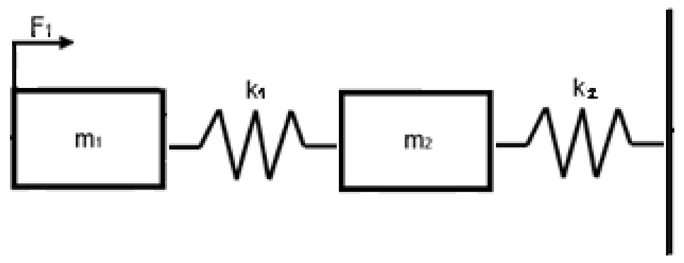
Figure 3A mechanical cascade model assumed for the purposes of this article consists of two masses (m1; m2) and two springs (k1; k2). The model is constrained to a rigid surface with a spring k2 and is being excited by an external force F1.
To calculate the weight of both masses and the stiffness of springs in the assumed model, it is necessary to insert input resonance frequencies into the dynamic characteristic of the model (1).
After substituting the variables with the given resonance frequencies and calculating equations in parentheses, the resulting polynomial equation takes the following form:
Now the resulting polynomial Eq. (2) can be split into a chain fraction as follows (Białas et al., 2009; Buchacz and Żurek, 2005; Buchacz et al., 1999):
Each of the following coefficients of Eq. (3) corresponds to the parameter associated with the next element of the synthesized model multiplied by a constant H. So, the resulting parameters of the assumed mechanical model, given that parameter H=1, are as follows: m1=1 kg, k1=170 N/m, m2=1675 kg, and k2 = 71 182 N/m. Parameter H and the excitation force F determine the amplitude of vibrations at the peaks of resonance frequencies. After the calculation of mechanical model parameters, an analogous electrical model was created using the voltage analogy. The calculated values of individual system components in voltage analogy are as follows: L1=1 H, C1=5882 mF, L2=1675 H, and C2 = 14 048 mF. A corresponding cascade electrical model made with the use of voltage analogy is presented in Fig. 4.
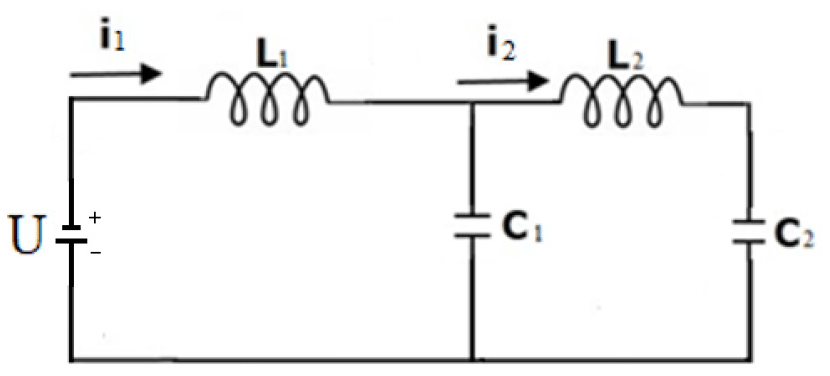
Figure 4Electrical cascade model of the case under consideration created with the use of voltage analogy to mechanical systems.
To complete the process of synthesizing both cascade models, equations of motion (4) and (5) were prepared, based on the obtained models.
Equation (4) shows a system of equations of motion derived from mechanical model. Equation (5) shows a system of equations of motion derived from electrical model. Equations (4) and (5) are needed when calculating the amplitudes of vibrations for resonant frequencies using a classical matrix method.
Graph models are graphical representations of interactions between elements in a system. Every relation between an object, its inertia and its relations with other elements can be presented in form of edges. Displacements of moving elements in a mechanical system or currents/voltages in an electrical system can be presented as vertices of the graph. All interactions that affect individual elements are presented as edges connecting each of the vertices. Solving the problem of synthesis with the help of graphs and structural numbers can greatly simplify the process of obtaining the required information from models (Bellert and Woźniacki, 1968; Wojnarowski et al., 1986; Kowal et al., 1995; Buchacz et al., 1999; Białas et al., 2009). It is especially valuable for obtaining the information needed for verification of synthesized systems, as the graph method, coupled with structural numbers, can provide easy form of calculating system outputs using standardized algorithms (Bellert and Woźniacki, 1968; Wojnarowski et al., 1986). To implement structural numbers into calculations, a standard model can be transformed into a graph model. Each edge of the graph represents one individual interaction between elements of the system. Due to a clear representation of relations, thanks to graphs, and a relatively simple set of instructions to calculate structural numbers, this method can significantly reduce the complexity of calculations and allow for the implementation of computer programming into the calculation process. The method has been developed for calculating complex electrical systems as one of its main purposes. There have been numerous attempts at adapting graphs and structural numbers to also solve mechanical models (Wojnarowski, 1977; Wojnarowski et al., 1986). Since the 1970s, this problem has also been researched at the Silesian University of Technology (Bellert and Woźniacki, 1968; Wojnarowski et al., 1986; Kowal et al., 1995; Buchacz et al., 1999; Białas et al., 2009). The structural number method is still considered as being a non-classical method of calculating complex system outputs.
To transform our model to a graph model, it is necessary to specify each relation between elements of a considered model. In case of the system considered in this article, displacement vertices will be presented as points 1x1 and 1x2, which represent the displacement of each of the two masses that exist in the mechanical model. The 1x0 vertex is considered as a base vertex. It represents a connection to the exterior of the system. The graph representation of displacement vertices and a base vertex can be seen in Fig. 5.
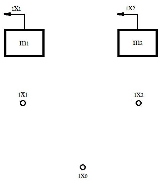
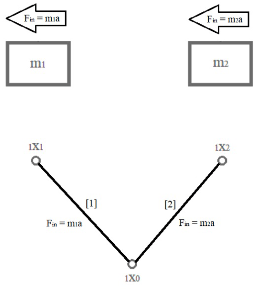
In the next step, it is necessary to model the inertia in the system. The inertia is represented in the form of edges that connect each vertex associated with moving masses in the system with the base vertex, representing the exterior of the system (Fig. 6).
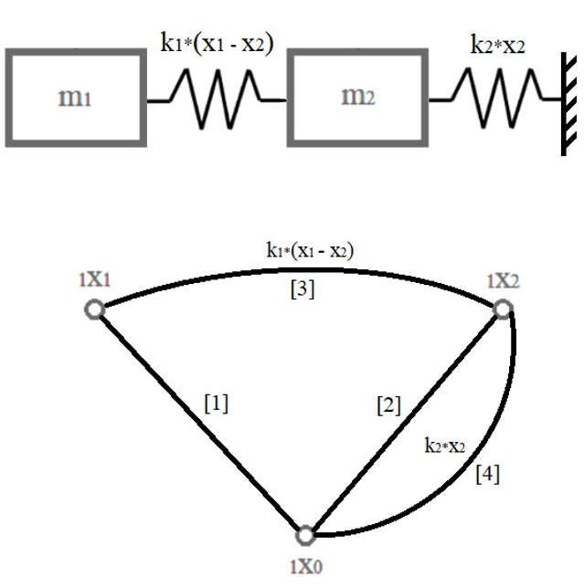
Loads of springs or damping factors of any dampers connected to masses are marked as the next set of edges, connecting the vertices of displacement (Fig. 7).
Last, all additional external forces acting on the system are marked. In this case, there is only one external force, F, acting on the mass, m1. A full graph representation of the modelled system can be seen in Fig. 8.
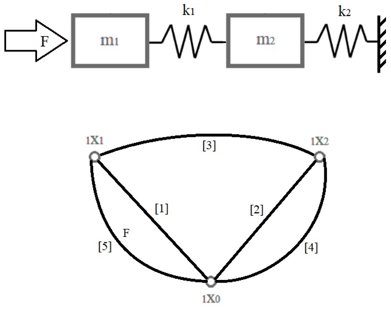
Explaining the graph markings again in bulk, the displacement of mass m1 is represented as vertex 1x1, and the displacement of the mass m2 is represented as the vertex 1x2. The inertia of mass m1 (m1a), or in the case of oscillating motion (−m1ω2), is marked as edge 1. The same goes for the inertial force of mass m2 being marked as edge 2. The load of the spring k1 that is tying the motion of two masses together is marked as edge 3. The load of the spring k2 tying the mass m2 to a rigid support surface is marked as edge 4. Last, the external force F1 acting on the mass m1 is marked as edge 5. It is important to note that this model and graph is only representing the motion in one dimension.
Converting the studied model into a graph model allows for easy calculation of its structural number. The structural number for a characteristic equation of a model is a numerical multiplication of the edges that are connected to n−1 vertices of the model (excluding edges that represent external forces; Białas et al., 2009; Buchacz and Żurek, 2005; Wojnarowski, 1977; Wojnarowski et al., 1986; Wróbel, 2018; Soluch et al., 1980). The structural number of the studied graph model takes the following form:
Calculating the structural number D(ω) lets us calculate the amplitudes of the model's resonant frequencies (among other characteristics) through the structural number equations. The general equation form for calculating each subsequent displacement amplitude (Białas et al., 2009; Buchacz and Żurek, 2005) is shown in Eq. (7).
where An is a subsequent amplitude value, D(ω) is a structural number calculated for the graph model (7), is the derivative of the structural number relative to edge n, is the simultaneity function of a structural number which geometric counter image contains edges i and j, and Fi is the forces acting on the system.
In case of the model under consideration, there are only two vertices that have any displacement. After substituting the equation variables with the data related to each calculated vertex and after converting the formulas, we are left with two equations for the displacement of each vertex as follows:
For the purposes of this article, an excitation force F was assumed to be 1N. Displacement amplitudes calculated from Eqs. (8) and (9) were plotted on the graphs in relation to the frequency spectrum. To verify the calculation done through the non-classical method of structural number algebra, an additional calculation of the displacements was also done through the classical method of matrix algebra. Calculations and graph plotting were done using the MATLAB R2019b calculation and programming software. Plotted graphs of the displacement of masses m1 and m2 are shown in Figs. 9 and 10.
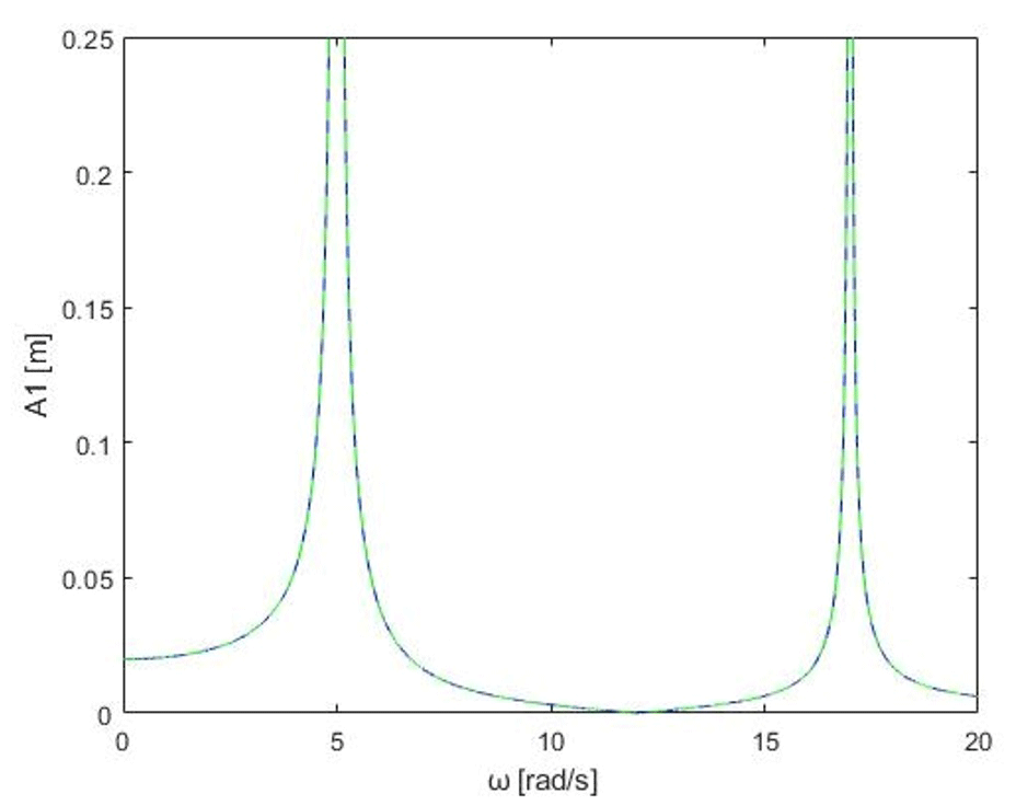
Figure 9Displacement graph of mass 1 in relation to the vibration frequency spectrum (blue plot – structural number calculus; green plot – classical calculus).
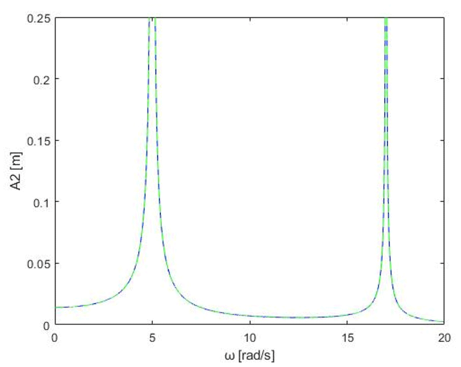
Figure 10Displacement graph of mass 2 in relation to vibration frequency spectrum (blue plot – structural number calculus; green plot – classical calculus).
Graphs in Figs. 9 and 10 show displacements of masses in the considered model in form of a fast Fourier transform (FFT) of oscillations for each mass. As we go along the x axis of oscillations, we can clearly notice two distinct peaks in the amplitude for the resonance frequencies. Those frequencies closely relate to resonant frequencies ω1 and ω3 that were assumed right at the start, which validates the proper representation of the model. Calculated through the classical method, using equations of motion (4) and derived matrix calculations based on those equations, are the resulting plots marked by the continuous green plot line. The dotted blue line represents the effect of calculations done using structural numbers. As can be seen, both methods produce almost identical results both in terms of the frequency and the peak vibration for the resonance frequencies. This shows that structural number method, while being better suited to more complex models because of its simplicity, can still produce solid results when compared to classical methods.
This section is devoted to possible adaptations of both classical and non-classical methods to the problem of complex piezoelectric model synthesis. Piezoelectric composites are materials that exchange energy between electrical and mechanical systems which require the inclusion of elements from both mechanical and electrical systems in the same model (Adriaens et al., 2000). In the current state of research, the authors have two conceptions on how to solve this problem. One conception involves creating an analogous cascade system, based on piezoelectric plates, with the help of graphs and structural numbers. The system would be capable of generating the same vibration pattern as the synthesized one. Another conception relies on the modification of the synthesized model to better accommodate relations existing in piezoelectric plates. The end goal involves creating a mechatronic model through either of those ways. Vibrations generated by the resulting system would be phase shifted to cancel out the vibrations incoming from target sources.
5.1 Synthesis of a piezoelectric model with the help of structural number algebra
To illustrate the process of creating a piezoelectric model, a stack consisting of two piezoelectric plates with unknown material properties and sizes was takes as an example. One end of the piezoelectric stack was fixed to a rigid surface, whereas the other end was vibrating without any constrain. Each piezoelectric plate was also connected to their individual electric circuits that excite their vibrations. Both plates are connected with each other's to create a system mechanically similar to the cascade system presented before. The model is presented in Fig. 11. Apart from existing mechanical forces and displacements, the system also has its own set of voltages and currents flowing through the plates, which adds another set of variables to the complexity of the system.

Figure 11Piezoelectric stack model that consists of two piezoelectric plates powered by separate electrical circuits.
The approach solely relying on the graph method and structural numbers would require a description of relations between mechanical elements of the system which consist of piezoelectric plates and their weights and stiffness. Additionally, an adequate link between the mechanical and electrical properties must be prepared to represent the electro–mechanical coupling inside the structure of every piezoelectric plate. Such a mathematical description was worked on in Soluch et al. (1980) and Buchacz and Wróbel (2010) and was represented in a form of graph with 3 degrees of freedom (two mechanical and one electrical) and three excitation forces (two mechanical forces and one voltage).
The mathematical model in the form of a matrix, representing all the inner dependencies between mechanical and electrical elements in a single, free-standing piezoelectric plate, is shown in Eq. (10).
Graphs, apart from the possibility of representing mechanical models, can also be used to represent dependencies in a matrix. In this case, the vertices iXj represent displacements (x1 and x2 by vertices 1X1 and 1X2) and currents flowing inside a single piezoelectric plate (i is represented as vertex 1X3). The edges connecting each vertex correspond to the elements in the matrix and represent relations between the inputs and outputs of the matrix equation. A graph representation of relations between elements in a single piezoelectric plate (Buchacz and Wróbel, 2010; Wróbel, 2018) is shown in Fig. 12.
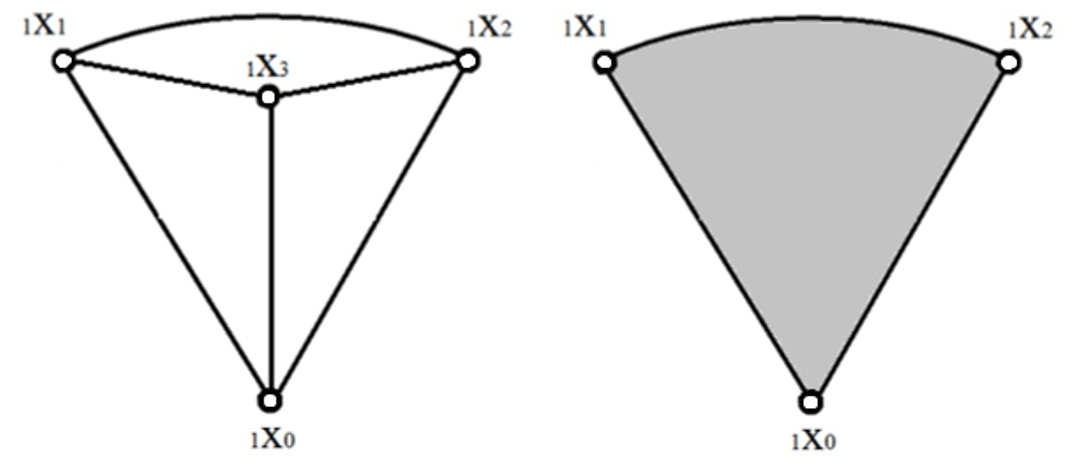
Figure 12Graph and a hypergraph of relations in a single non-constrained piezoelectric plate (Buchacz and Wróbel, 2010).
The hypergraph is a representation of only the outer edges and vertices of a graph with the internal connections and dependencies being treated as a form of a black box. To reflect the model with more than one piezoelectric plate, a single hypergraph can be duplicated and connected with the previous graph to create a complex hypergraph. The bottom of the first plate was constrained, which is represented by connecting the vertices 1X0 and 1X3. The new plate, represented by another hypergraph, was connected with the first one by one of their bases, which was represented by connecting the 1X1 vertex of the first hypergraph with a vertex of the second one. The modified version (after adding constraints and external forces) can be seen in Fig. 13. This model is an attempt at creating a piezo stack solely using graphs and structural numbers.

Figure 13Modified hypergraph of a piezo stack constrained on one side and excited by the force F on the other.
To solve this hypergraph, it would be necessary to conduct a reduction of the vertices by structural number operations (Bellert and Woźniacki, 1968; Wróbel, 2018) and then derive the equations from each edge of the resulting graph, effectively turning this complex graph back into a simpler form with reduced number of vertices and edges. It is then possible to convert the graph back into a matrix equation in the same fashion as the matrix was converted into a graph, to extract the equations necessary for solving the model. Another solution, which is still a working thesis, is that, by comparing displacements of vertices in the mechanical/electrical model created through the cascade model synthesis with the comparable model representing a piezo stack, it is possible to calculate parameters of piezoelectric plates and their supplying voltages (assuming that, in the event of the system being indeterminate, it is possible to assume boundary conditions in form of piezoelectric material properties or piezoelectric plate dimensions). For this model to be viable, it is also necessary to simplify the four-vertex hypergraph into a three-vertex graph. It is possible, again, with structural number algebra (as seen in Bellert and Woźniacki, 1968; Soluch et al., 1980; Buchacz and Wróbel, 2010).
where An is the subsequent amplitude value, Anp is the subsequent amplitude value of the piezoelectric stack, and is the frequency of the voltage fluctuations exciting the piezo stack.
5.2 Synthesis of a piezoelectric model through mechanical/electrical system accommodation
Another approach to the problem of synthesizing a model representing a piezoelectric system is through the use of an equivalent circuit based on a modified Kelvin–Voigt lumped model. An equivalent circuit would be created by extending the existing model derived in Sect. 2, with additional elements representing the electromechanical coupling and properties of piezoelectric plates (Adriaens et al., 2000; Lin, 1997; Goldfarb and Celanovic, 1997; Wang et al., 2011). In the case of the synthesized model, it is necessary to account for piezoelectric physical properties, such as strain, elasticity and mass, and for its electrical properties, such as impedance or capacitance. To consider those properties, an equivalent model was proposed based on Adriaens et al. (2000), Lin (1997), Goldfarb and Celanovic (1997) and Wang et al. (2011). The model can be seen in Fig. 14.
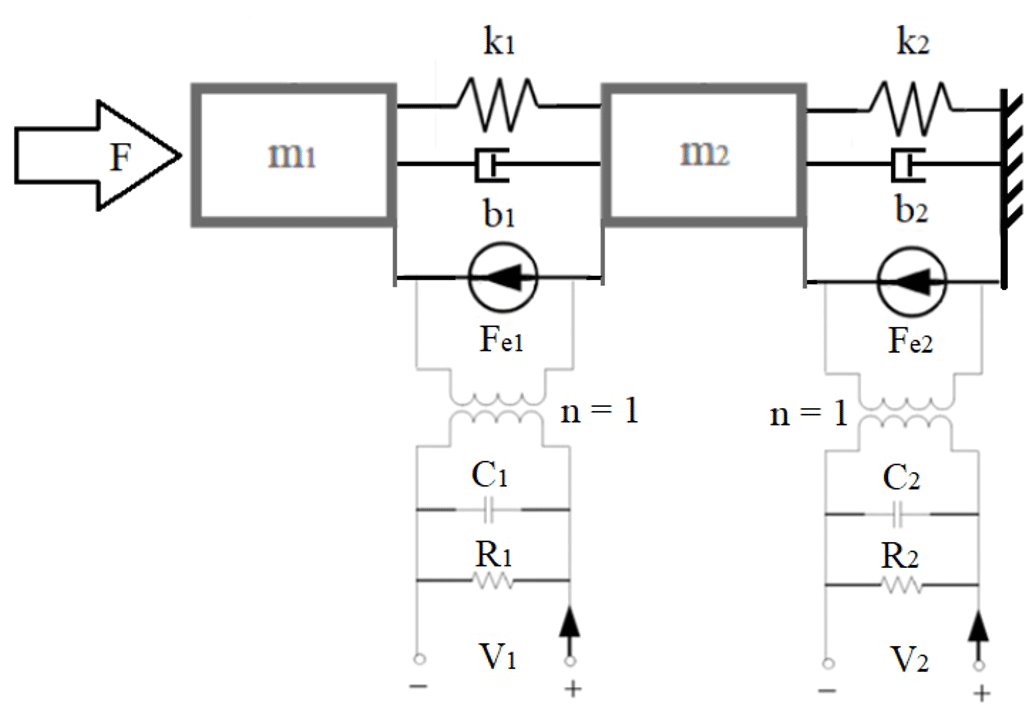
Masses m1 and m2 represent masses of the piezoelectric plates. Spring loads k1 and k2 represent the elasticity of piezoelectric material. Dampening factors b1 and b2 represent mechanical energy dispersion in the piezoelectric plate medium. Forces Fe1 and Fe2 represent the electromechanical coupling between the electrical system and mechanical system. Capacitance C1 and C2 represent the capacitive properties of piezoelectric plates. Resistance R1 and R2 represent the impedance of each piezoelectric plate in the system. Last, voltages V1 and V2 represent the voltage that is either coming out of piezoelectric plates (when passive) or input voltage (when active). This model could then be used to derive the same set of equations or matrixes that would be used to determine the variables representing each of the elements in the system.
Models presented in Sect. 5 were created with the use of non-classical and classical methods with slight individual modifications to better accommodate them to solving the model. Structural numbers and graphs shine when it comes to the relative simplicity in transitioning (or determining) the necessary equations for solving the output of complex models. There are documented cases of structural numbers being used to create computer algorithms for calculation (Wojnarowski, 1977, 1981; Wojnarowski et al., 1986; Buchacz et al., 1997), which also encourages the use of computational methods to aid in faster and more accurate calculation. The problem of adapting the model to suit piezoelectric plates through the pure use of graphs and structural numbers lies in the rapid increase in difficulty when it comes to reducing the complex hypergraphs back into a simple form of graphs that can be translated back into the necessary equations. An attempt to mitigate that difficulty can be made by taking only some part of the graphs and deriving partial equations from them, but this solution is still a theory, and the possibility of application still needs to be verified. On the other hand, classical methods, such as the modified Kelvin–Voigt lumped model, offer more transparent approach with clearer draft of the elements that compose the model but are tougher to translate into the equations that have to be derived in order to solve the model. Both solutions are still in the theoretical stage and need empirical tests and further study to eliminate dead ends and verify the soundness of each solution in a practical application. Judging from the progress that has been done so far, it is possible that the best solution would involve using parts of both presented approaches. The Kelvin–Voigt lumped model is good in terms of the transparency of the model and allows for easy identification of the variables that exist in the system. On the other hand, graphs and structural numbers are good for deriving the equations that are necessary to solve the model. A good solution would combine the transparency of the classical method with the facilities offered by structural numbers. An example of a mechanical system with 2 degrees of freedom showcased in this article is just one system that can be synthesized this way. There is no theoretical limitation to the complexity of such cascade system in terms of its degrees of freedom.
The development of new synthesis methods allowed for a simplified and more elastic approach to issues of designing models that must meet the required parameters. This article was focused on using methods well explored by various researchers (Bellert and Woźniacki, 1968; Wojnarowski, 1981; Wojnarowski et al., 1986; Buchacz et al., 1997, 1999; Buchacz and Żurek, 2005; Białas et al., 2009; Buchacz and Wróbel, 2010; Białas, 2012; Białas and Buchacz, 2014) to create a backbone for new possible applications through the introduction of piezoelectric materials. Piezo stack models are harder to synthesize through classical methods because of their complex internal relations between mechanical and electrical properties (Wojnarowski, 1981; Wojnarowski et al., 1986; Buchacz and Wróbel, 2010). With the combination of known synthesis methods and information gathered on the topic of piezoelectric materials, the authors made an attempt to find a solution to the problem of synthesizing a piezoelectric model. The proposed solution is, however, still in its infancy and requires further investigation and research through verification by using other mathematical methods and with thorough testing on actual physical models. The next phase of the project involves a more practical approach in the form of the empirical testing of piezoelectric bimorphs and stacks to gather a deeper understanding about the internal relations in the structure of piezoelectric plates and between their mechanical and electrical properties. Knowledge gathered in the experiments will help verify the usefulness and validity of the proposed solutions and help to refine the model.
The hopes are that the derived method for solving complex systems with piezoelectric plates allows the making of complex piezoelectric active dampers with an ability to adjust their damping capabilities to the spectrum of vibrations generated by the machinery. It may also be possible to implement some form of energy recovery with piezoelectric plates, but this case needs a lot more studying. The concept of using piezoelectric materials to actively dampen vibrations is a novelty that is being researched by various researchers (Vijay et al., 1995), and this project aims at broadening the flexibility and applicability of these solutions in various areas of the industry, such as automotive or manufacturing industries.
Currently, all calculations performed in MATLAB R2019b and the programme itself are stored locally. All data will be provided on request, however.
AW took responsibility for the concept, supervision and initial review of the completed article. JH took responsibility for the review of the literature, calculations, simulations and writing the paper.
The contact author has declared that neither they nor their co-author has any competing interests.
Publisher’s note: Copernicus Publications remains neutral with regard to jurisdictional claims in published maps and institutional affiliations.
Jacek Harazin would like to thank his promoter and all of his colleagues for their aid in understanding the principles that laid the foundation for this article. All the reviewers, who spent their time on numerous reviews and pointing out all the problems or inconsistencies while also providing useful guidance, are thanked. As a doctoral student, Jacek Harazin has learned a lot thanks to this process, and he would also like to thank the editors for the time spent on corrections and adjustments to bring this article up to standard.
This paper was edited by Daniel Condurache and reviewed by four anonymous referees.
Adriaens, H., Koning, W., and Banning, R.: Modeling piezoelectric actuators, IEEE/ASME T. Mech., 5, 4, https://doi.org/10.1109/3516.891044, 2000.
Bellert, S. and Woźniacki, H.: Analysis and synthesis of electrical systems by the structural number method [Analiza I synteza układów elektrycznych metodą liczb strukturalnych], WNT, Poland, 1968 (in Polish).
Benjeddou, A. and Ranger, J. A.: Use of shunted shear-mode piezoceramics for structural vibration passive damping, Comput. Struct., 84, 22–23, 1415–1425, https://doi.org/10.1016/j.compstruc.2005.10.010, 2006.
Bergamo, E., Fasan, M., and Bedon, C.: Predictivity of CNC machine-induced vibrations on inter-story floors based on coupled experimental-numerical investigations, in: Proceedings of First International Electronic Conference on Actuator Technology: Materials, Devices and Applications, 23–27 November 2020, https://doi.org/10.3390/IeCAT2020-08529, 2020
Białas, K.: Application of mechanical and electric elements as implementation of active reduction of vibration, Journal of Achievements in Materials and Manufacturing Engineering, 55, 523–528, 2012.
Białas, K. and Buchacz, A.: The Influence of Changing the Parameters of Electrical Components Implementing the Active Reduction of Vibration, Appl. Mech. Mater., 657, 614–618, https://doi.org/10.4028/www.scientific.net/AMM.657.614, 2014.
Białas, K., Buchacz, A., and Dzitkowski, T.: Synthesis of vibrating active mechanical systems with damping in terms of the polar graphs and structural numbers [Synteza drgających aktywnych układów mechanicznych z tłumieniem w ujęciu grafów biegunowych i liczb strukturalnych], Wydawnictwo Politechniki Śląskiej, ISBN 978-83-7335-633-7, 2009 (in Polish).
Brownjohn, J. and and Pavic, A.: Vibration control of ultra-sensitive facilities, in: Proceedings of the Institution of Civil Engineers, Structures and Buildings, October 2006, 159, 295–306, https://doi.org/10.1680/stbu.2006.159.5.295, 2006
Buchacz, A. and Wróbel, A.: Modeling and study of the effect of piezoelectric phenomenon on the characteristics of a mechanical system [Modelowanie i badanie wpływu zjawiska piezoelektrycznego na charakterystyki układu mechanicznego], Wydawnictwo Politechniki Śląskiej, ISBN 978-83-7335-682-5, Poland, 2010 (in Polish).
Buchacz, A. and Żurek, K.: The inverse task of dynamics of active mechanical systems in terms of graphs and structural numbers [Odwrotne zadanie dynamiki aktywnych układów mechanicznych w ujęciu grafów i liczb strukturalnych], Wydawnictwo Politechniki Śląskiej, ISBN 83-7335-184-1, Poland, 2005 (in Polish).
Buchacz, A., Wojnarowski, J., Świder, J., Pasek, M., Czyż, B., Dąbek, A., Ziemski, M., and Żochowski, L.: Computer aided synthesis and analysis of machine components modelled by graphs and structured numbers [Komputerowe wspomaganie syntezy i analizy podzespołów maszyn modelowanych grafami i liczbami strukturalnymi], ZN Pol. Śląskiej, s. Mechanika, 127, PL ISSN 0434-0817, Poland, 1997 (in Polish).
Buchacz, A., Dymarek, A., and Dzitkowski T.: Synthesis of discrete, continuous and discrete-continuous vibrating systems represented by graphs, Sixth International Scientific and Engineering Conference – Machine-Building and Technosphere on the Border of the XXI Century, Donetsk 1999, 3, 243–245, 1999.
Dassisti, M., Olabi, A. G., and Brunetti, G.: Application of magnetorheological fluids MRF in a suspension system, Materials Science and Materials Engineering, Elsevier, Italy, 2021.
Du, H., Li, W., Ning, D., Sun, S., and Zhu, Q. M.: Advanced seat suspension control system design for heavy duty vehicles, Emerging Methodologies and Applications in Modelling, Academic Press, 37–56, https://doi.org/10.1016/B978-0-12-819601-4.00003-5, 2020.
Goldfarb, M. and Celanovic, N.: Modeling piezoelectric stack actuators for control of micromanipulation, IEEE Contr. Syst. Mag., 17, 3, https://doi.org/10.1109/37.588158, 1997.
Hagood, N. W. and Flotow, A.: Damping of structural vibrations with piezoelectric materials and passive electrical networks, J. Sound. Vib., 146, 243–268, https://doi.org/10.1016/0022-460X(91)90762-9, 2003.
Kowal, J., Szymkat, M., and Uhl, T.: Synthesis and Analysis of Active Suspension Control, in: Proceedings of the 1995 International Symposium on Active Control of Sound and Vibration, Newport Beach, California, USA, 6–8 July 1995, 346–351, 1995.
Kozek, M., Benatzky, C., Schirrer, A., and Stribersky, A.: Vibration damping of a flexible car body structure using piezo-stack actuators, Control Eng. Pract., 19, 298–310, https://doi.org/10.1016/j.conengprac.2009.08.001, 2011.
Lin, C.: Design and analysis of piezoelectric transformer converters, Virginia Tech, Doctoral Dissertations, available at: http://hdl.handle.net/10919/30723 (last access: 24 October 2021), 1997.
Lyon, R. H.: Machinery Noise and Diagnostics, 1st Edn., Butterworth-Heinemann, Stoneham, MA, USA, https://doi.org/10.1016/C2009-0-24812-4, 1987.
Mohanta, R. K., Chellian, T. R., Allamsetty, S., Akula, A., and, Ghosh, R.: Sources of vibration and their treatment in hydro power stations-A review, Eng. Sci. Technol., 20, 637–648, https://doi.org/10.1016/j.jestch.2016.11.004, 2017.
Rivin, E.: Vibration isolation theory, Encyclopedia of Vibration, Academic Press, Wayne State University, Detroit, MI, USA, 1487–1506, https://doi.org/10.1006/rwvb.2001.0179, 2001.
Salokyova, S., Krehel, R., Pollak, M., and Kocisko, M.: Research on impacts of mechanical vibrations on the production machine to its rate of change of technical state, Adv. Mech. Eng., 8, 1–10, https://doi.org/10.1177/1687814016655778, 2016.
Shrestha, B.: Study of building vibrations caused by machinery, PhD, University of New Mexico, available at: https://digitalrepository.unm.edu/ce_etds/201/ (last access: 24 October 2021), 2018.
Soluch, W., et al.: Introduction to piezoelectrics [Wstęp do piezoelektryki], Wydawnictwo Komunikacji i Łączności, ISBN 83-206-0041-3, Poland, 1980 (in Polish).
Tavner, P. J.: Review of condition monitoring of rotating electrical machines, IET Electr. Power App., 2, 215–247, https://doi.org/10.1049/iet-epa:20070280, 2008.
Vijay, K., Vasundara, V., Xiao-Qi, Carney, B., Olinger, J. L., and Coffey, F. S.: Active noise control using piezoelectric sensors and actuators, Owens Corning Fiberglas Technology Inc., US5668744A Patent, 1995.
Wang, S.-H. and Tsai, M.-C.: Dynamic modeling of thickness-mode piezoelectric transducer using the block diagram approach, Ultrasonics, 51, 5, 617–624, https://doi.org/10.1016/j.ultras.2011.01.002, 2011.
Wojnarowski, J.: Graphs and structured numbers as models of mechanical systems [Grafy i liczby strukturalne jako modele układów mechanicznych], Polskie Towarzystwo Mechaniki Teoretycznej i Stosowanej, Poland, 1977 (in Polish).
Wojnarowski, J.: Application of graphs in the analysis of vibrations of mechanical systems [Zastosowanie grafów w analizie drgań układów mechanicznych], PWN, ISBN 83-01-02971-4, Poland, 1981 (in Polish).
Wojnarowski, J., Buchacz, A., Nowak, A., and Świder, J.: Modelling of vibrations of mechanical systems by methods of graphs and structural numbers [Modelowanie drgań układów mechanicznych metodami grafów i liczb strukturalnych], Gliwice: Skrypty uczelniane Politechniki Śląskiej, no. 1266, PL ISSN 0434-0825, Poland, 1986 (in Polish).
Wróbel, A.: Classical and non-classical research methods and experimental studies of piezoelectric plates, Wydawnictwo Politechniki Śląskiej, ISBN 978-83-7880-545-8, Poland, 2018.
- Abstract
- Introduction
- Cascade model synthesis
- Graph model of a cascade system
- Structural number method and displacement calculation
- Probable piezoelectric system adaptation methods
- Discussion
- Conclusions
- Code and data availability
- Author contributions
- Competing interests
- Disclaimer
- Acknowledgements
- Review statement
- References