the Creative Commons Attribution 4.0 License.
the Creative Commons Attribution 4.0 License.
 | 04 Oct 2021
A toy-inspired kirigami pattern and its kinematic performance by applying mechanisms and machine theory
Weiwei Lin
Kunjing Chen
Yuan Gao
Aihua Chen
Huijuan Feng
Origami that can form various shapes by setting simple creases on the paper and folding along these creases has a lot of applications from the fields of art to engineering. The inverse problem of origami that determines the distribution of creases based on the desired shape is very complicated. In this paper, we use theoretical kinematics to systematically analyse an inverse folding problem of a toy about how to fold a piece of paper into a disc through a smaller hole without breaking it. The results show that some four-crease and six-crease patterns can achieve the expected function, and they can be easily folded with 1 degree of freedom (DOF). It not only opens up a new way to solve the inverse folding problem but also helps students to understand mechanisms and machine theory.
- Article
(7889 KB) - Full-text XML
- BibTeX
- EndNote


Origami, a kind of traditional art of paper folding originating in East Asia, has attracted much attention in the fields of science and engineering due to the property that it can generate a large number of 3D structures by setting creases on a piece of paper. In mechanism, Zhang and Chen utilized origami to find some mobile assemblies of overconstrained linkages (Zhang and Chen, 2018). In biology, origami was applied in DNA nanotechnology (Marras et al., 2019; Masayuki and Hiroshi, 2018). In engineering, a variable-diameter wheel was designed for a wheel-driven robot using an origami structure (Lee et al., 2017, 2021), Meanwhile, Pesenti et al. (2015) used an origami pattern to reduce energy consumption for indoor climate control as well as artificial lighting and offered visual comfort for users (Pesenti et al., 2015). Because there are always lots of creases in an origami pattern and the topology is quite complex, some numerical approaches (Yu et al., 2019; Deng et al., 2020) were proposed to study the folding behaviour of origami patterns. To further satisfy the need of practical applications, some scholars paid attention to the folding of thick-panel origami patterns and proposed some solutions (Chen et al., 2015; Zhang and Chen, 2019; Hull and Tachi, 2017).
On some particular occasions, some holes have to be cut in the paper before folding, and this variation of origami is called kirigami. The interference among the sides of holes can be utilized to block the folding, which benefits the load-bearing capacity of self-locking mechanical metamaterials (Fang et al., 2018) and self-locking structures (Wang et al., 2020). Comparing with normal origami patterns, the gaps make kirigami patterns easier to deform, facilitating the applications of kirigami in some engineering areas. For example, Rafsanjani et al. (2018) and Yang et al. (2021) designed some crawlers with kirigami patterns. Some graded conventional/auxetic honeycomb cores were designed by Hou et al. (2014). Lin et al. (2016) got a synthetic Buckliball, and Zhang et al. (2015) drove an assembly of 3D mesostructures of diverse materials from 2D micromembranes or nanomembranes.
Recently, an interesting toy of the paper-folding problem on how to get a round disc through a smaller square hole in a piece of paper (see Fig. 1) has attracted the attention of the authors. The problem was proposed by Tadashi Tokieda, who is a mathematician from Stanford University. As Tadashi Tokieda explained, the 2D paper is transferred into a 3D structure when being folded up off the table by twisting the paper, and the disc can then pass the smaller hole (Haran, 2021). However, the mechanism behind the problem such as creating creases by twisting the paper and the folding process has not been explained explicitly yet.
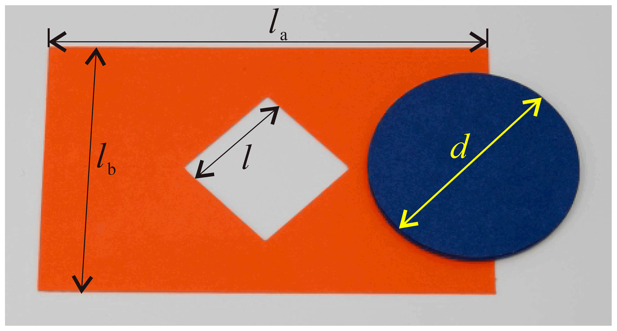
Figure 1A paper folding toy: how to get a round disc through a smaller square hole in a piece of paper.
Therefore, the target of this paper is to systematically find proper kirigami patterns that can realize the function of allowing a round disc to pass through a smaller square hole in a piece of paper, namely to determine the distribution of creases. Meanwhile, the folding process will be explained by kinematic analysis. The remaining parts are structured as follows. Section 2 is to describe the problem from the mechanical engineering perspective. The construction process of the kirigami patterns is given by kinematic analysis in Sect. 3. Conclusions are drawn in Sect. 4 to end the paper.
Ignoring the deformation of paper panels and only allowing the folding around creases, an origami pattern is equivalent to a linkage by viewing creases as revolute joints (R joints) and paper panels as links. In origami, a four-crease pattern (see Fig. 2a) is the most classical origami with the least number of creases; hence, we choose it as an example to show the equivalent property (see Fig. 2b).
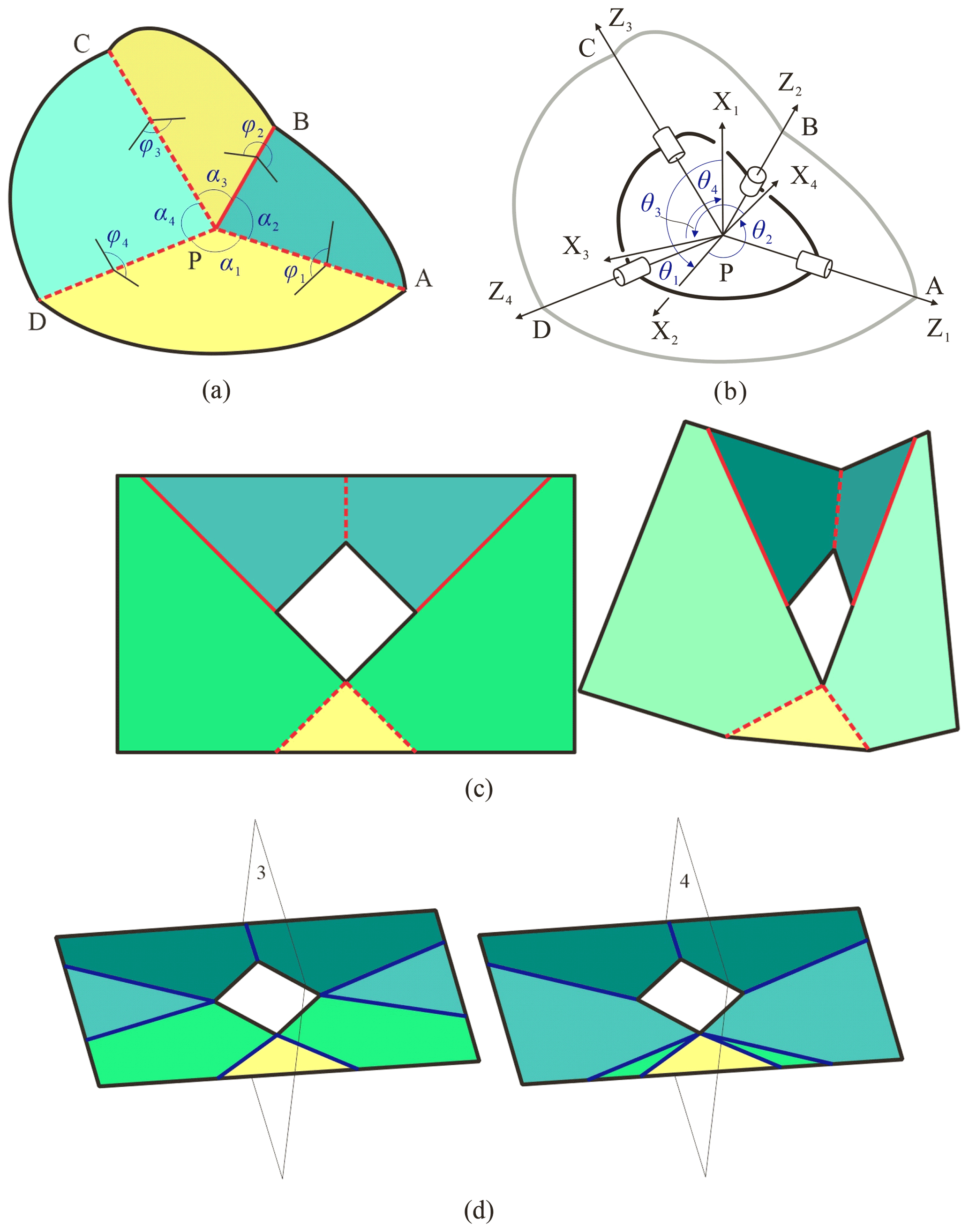
Figure 2(a) The origami with four creases. (b) The local coordinate systems on the equivalent 4R linkage. (c) The movable five-crease pattern becomes a 2-DOF spherical 5R linkage. (d) Two possible seven-crease patterns are not flat-foldable.
Since we are interested in the folding performance of the origami pattern, the relative motion among links in the linkage ought to be concerned. Therefore, local coordinate systems at creases are established according to D–H notation (Denavit and Hartenberg, 1955), where the z axis directs from the vertex P to the outside along each crease; the direction of the x axis is determined by the right-hand rule, namely , and the y axis is determined by the right-hand rule (see Fig. 2b). Therefore, the relationships among kinematic variables in spherical 4R linkage (Chiang, 1988) are
where
where α is the twist angle, and θ is the revolute angle (variable). To describe the folding more intuitively, upper-dihedral angles, φ, are adopted (see Fig. 2a). In this paper, all of the upper-dihedral angles are the angles between two adjacent panels and are measured from upwards, namely φ<π means that the corresponding creases are valley ones represented by dashed lines, and situations of φ>π are for mountain creases represented by solid lines. Here,
Therefore, the kinematic relationships can be expressed by the upper-dihedral angles
where
In the view of mechanical engineering, the target is to assign creases to generate a kirigami pattern. To facilitate the folding, these equivalent linkages are expected to be of 1 degree of freedom (DOF), and the distribution of creases is preferred to be symmetric to simplify the folding process. According to the classical G–K (Grübler–Kutzbach) criterion (Huang, 2004), single-loop spatial linkages must be with multi-DOFs when the number of links is larger than seven. On the other hand, the least number of movable spatial linkages is four. Therefore, the number of creases of possible kirigami patterns must belong to . To make the obtained pattern easy to fold, the creases are hoped to be symmetrically distributed. For five-bar spatial linkages, only the Myard 5R linkage (Liu and Chen, 2009) is plane-symmetric, which will become a 2-DOF spherical 5R linkage when all link lengths are taken zero in zero-thickness origami (see Fig. 2c). Figure 2d shows the two possible situations for the seven-crease pattern with plane symmetry, where planes 3 and 4 are the symmetric planes, and all panels are expected to be folded to the corresponding planes with 1 DOF. However, the yellow panels can never be folded into these symmetric planes, namely seven-crease patterns are not flat-foldable. Therefore, there are two possible assignments, four-crease and six-crease patterns, to be studied. Meanwhile, in order to allow the disc to pass through the smaller square hole, one of the distances between a pair of alternating vertices of the square hole should be as large as possible and not smaller than the diameter of the disc. Therefore, the following section will evaluate the distances of the two possibilities during the folding.
For convenience, the side length of the square hole is denoted as l, the size length of the paper is la by lb, and the diameter of the disc is d, which is larger than and smaller than 2l. The two possible situations, four-crease and six-crease patterns, are studied as follows.
3.1 Four-crease pattern
Figure 3 shows the situation of setting four creases on the paper, where the angles between each pair of adjacent creases, namely the twist angles, are α and β. Due to the symmetric property, . Crease AA′ is chosen as a valley one for convenience. According to Hull (1994), creases BB′, CC′, and DD′ are valley, mountain, and valley creases, respectively, and the pattern is flat-foldable; then φ1, φ2, , and .

Figure 3The four-crease pattern (a) at the deployed configuration, and (b) at the folding configuration.
It is easy to find that the distance between B and D rapidly becomes smaller during the folding; the disc thus could not pass the hole along this gap. For the gap along AC, some auxiliary lines are added to evaluate the distance. For example, perpendicular lines of BB′ crossing A and C, respectively, AM and CN, are drawn, where M and N are vertical feet (see Fig. 3a and b). Line segment MQ is determined to be parallel to and equal to NC. Then, CQ, AQ, and AC are connected independently (see Fig. 3b). According to the geometric properties of the pattern, the following conditions are satisfied (see Fig. 3a):
In ΔAQM, ∠AMQ=φ2 (see Fig. 3b); then
Due to AQ⊥CQ,
Since φ2 varies from π to 0 when the pattern is folded from the deployed configuration to the folded one, lAC is monotonically increasing and will become the largest value, , at the fully folded configuration. Therefore, if d≤2lcos α, the disc can pass through this hole by folding the four-crease pattern; otherwise, the disc could not.
3.2 Six-crease pattern
Based on the four-crease pattern, two additional creases, BB′′ and DD′′, are introduced (see Fig. 4). Similarly, AA′ is also chosen as a valley crease for reference. The corresponding mechanism is a plane-symmetric Bricard linkage with the following parameters:
where 0<α, β, γ<π, , , and . The relationship among kinematic variables (Feng, 2015) is
where
Here, variable I has two solutions, which represent two moving paths. I remains zero in one of the solutions, which means there is no folding along creases BB′ and DD′, and it degenerates to a spherical 4R mode. The situation, I=0, is thus not considered in the following analysis, then
Because γ will determine the positions of the added creases (i.e. BB′′ and DD′′) and the range of γ (i.e. , , ) will also influence the distribution of mountain or valley creases, we will study the three ranges as three schemes I, II, and III, respectively. It should be noticed that when , Eqs. (9)–(11) become, by considering Eq. (14),
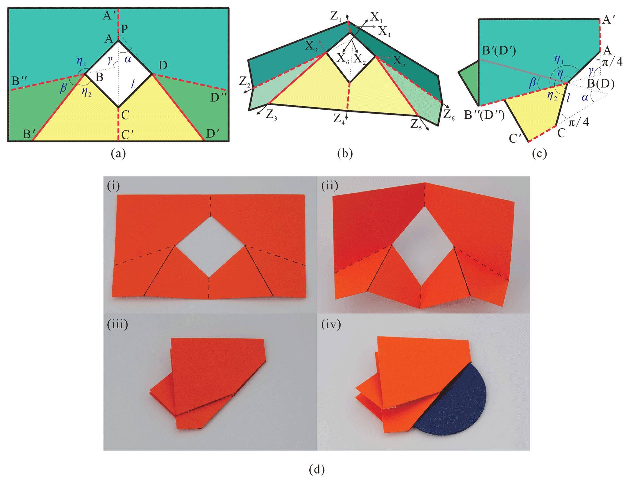
Figure 4The six-crease pattern for scheme I with parameters , , (a) at the deployed configuration, (b) at the folding configuration, and (c) at the fully folded configuration, demonstrated with (d) the folding sequence of a physical model.
3.2.1 Scheme I for
When (see Fig. 4), the relationship between upper-dihedral angles and revolute variables is
Substituting Eqs. (18)–(20) into Eqs. (15) and (16),
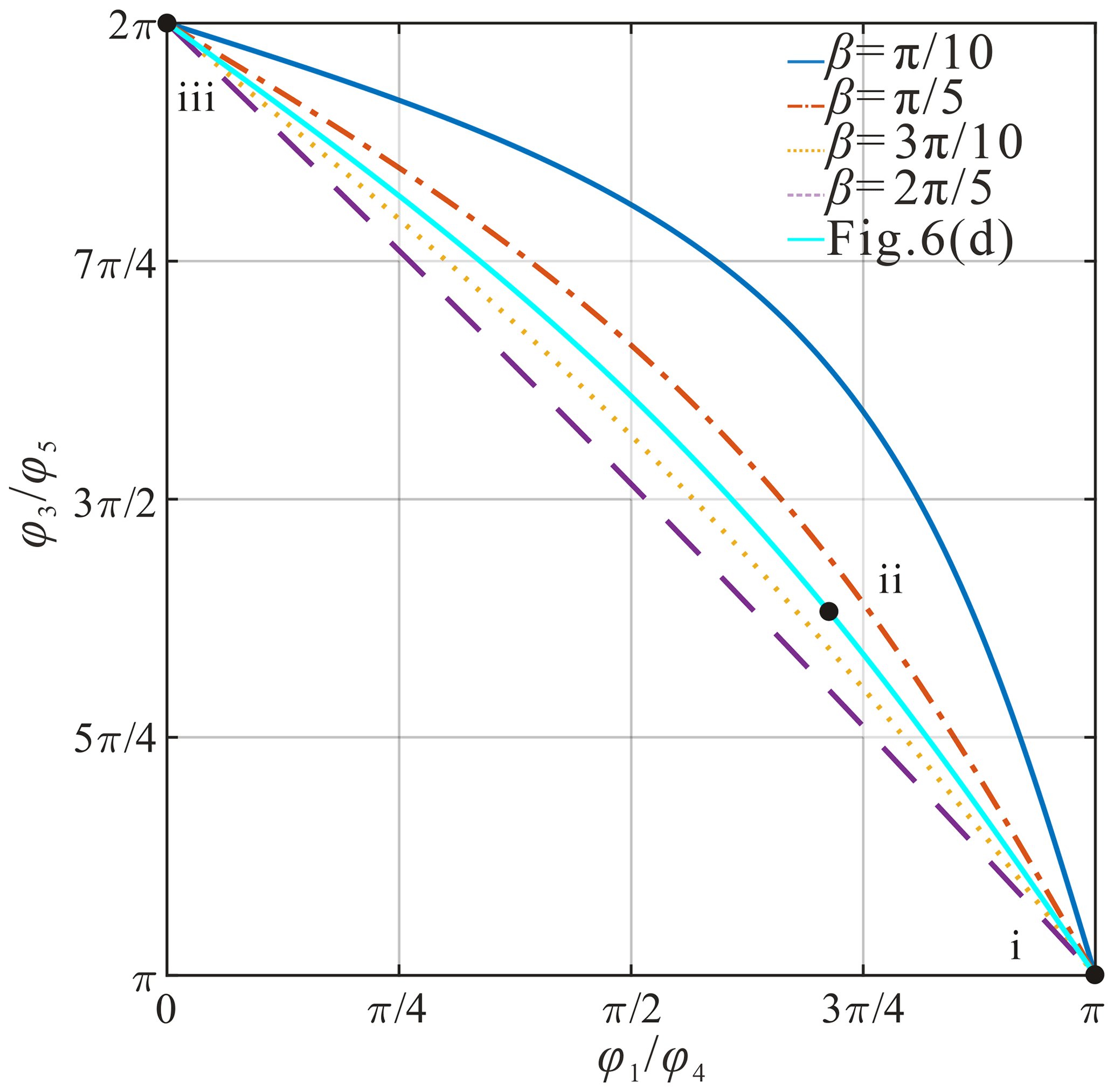
According to Eqs. (21)–(23), when φ2=π and , the pattern locates at the fully deployable configuration. While φ2=0, , and , the pattern is always flat-foldable. To show the folding performance in detail, Fig. 5 shows the curves among upper-dihedral angles for , , when . All curves pass through the point (π, π), which represents the deployed configuration in a plane, and pass the point (0, 0), which represents the fully folded configuration in a plane. The types of creases 1, 2, 4, and 6 are the same and are different from those of creases 3 and 5 according to the range of upper-dihedral angles, and the pattern could be folded along two sides due to . The distance between A and C can be obtained by the transformation of coordinate systems. In system 1,
and in system 4,
It can be transformed into system 1,
in which Tij represents the transformation matrix from system i to system j (Dai, 2014):
Then, the distance between A and C is
To make the disc through the hole, the largest value of lAC should be larger than d, . According to the above-mentioned analysis, the pattern is flat-foldable. Figure 4c shows the fully folded configuration, in which lAC, f is related to η,
Then,
Therefore, when , lAC, f will reach the largest value, , and the disc can definitely pass through the hole. Figure 4d shows the folding sequence with three states of a model, , , , the fully deployed configuration, a middle state, and the fully folded configuration, where dashed lines represent valley creases and solid lines show the mountain creases.
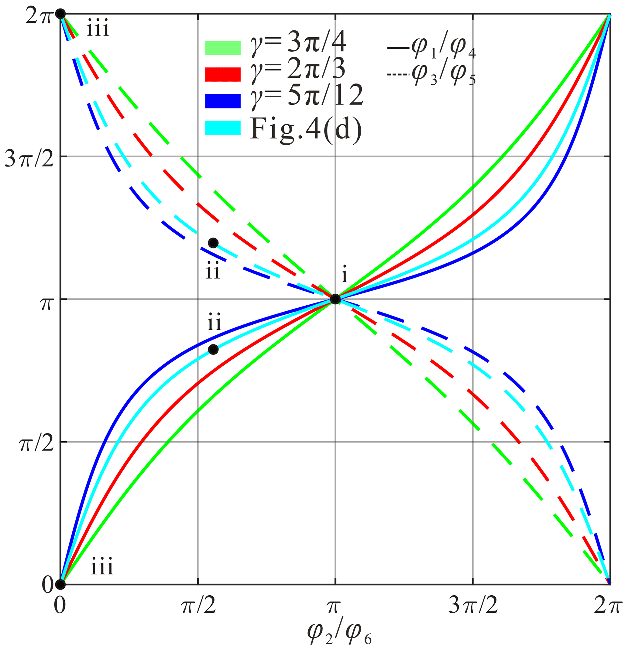
Figure 5The kinematic curves for scheme I among upper-dihedral angles φ1, φ3, φ4, φ5 vs. φ2(φ6).
3.2.2 Scheme II for
When (see Fig. 6), the degenerated condition is from a plane-symmetric Bricard linkage to a movable 4R linkage, Eq. (20) in Feng (2015) is satisfied. The plane-symmetric Bricard linkage works as a spherical 4R mode along creases AA′, BB′, CC′, and DD′ after panels and overlap panels and , respectively, and (see Fig. 6b). Obviously, the twist angles of the 4R linkage are
Then, the kinematic relationship, expressed with upper-dihedral angles, can be obtained from Eq. (3),
The curves among upper-dihedral angles for , , , , are given in Fig. 7, which show that all of them can be fully folded too. It shows that creases 1 and 4 move as valleys while creases 3 and 5 move synchronously as mountains due to physical interference. Similarly, by observing Eqs. (34) and (35), the pattern could also be flat-foldable. Figure 6c shows the pattern at the fully folded configuration, in which lAC, f can be calculated with Eq. (31) too. Therefore, when , lAC, f will reach the largest value, , and the pattern can also realize the desired function, which is demonstrated with a model, , , (see Fig. 6d). It should be noticed that the solution of Tadashi Tokieda is just one particular situation of this scheme.
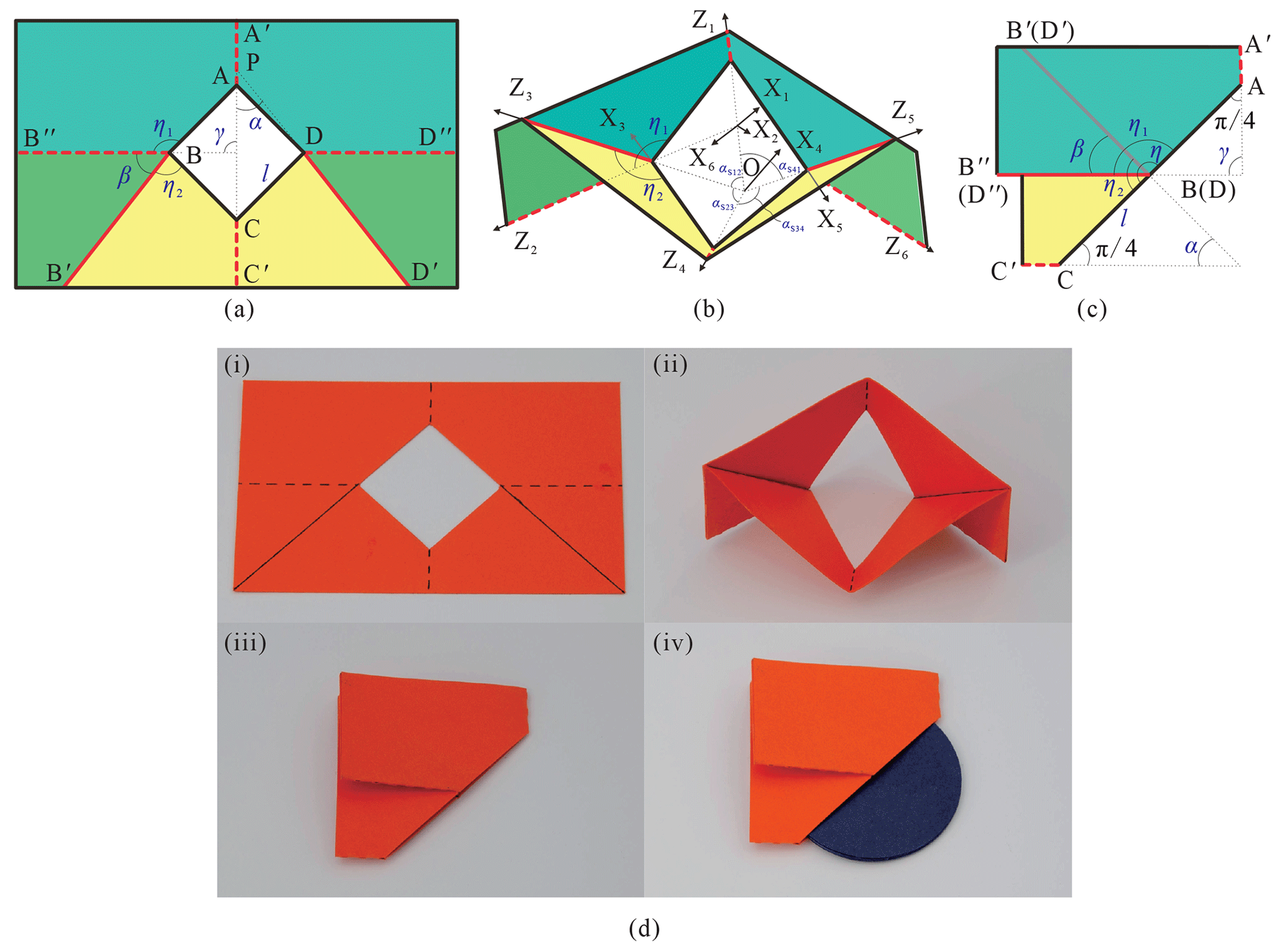
Figure 6The six-crease pattern for scheme II with parameters , , , which is the solution from Tadashi Tokieda (a) at the deployed configuration, (b) at the folding configuration, and (c) at the fully folded configuration, demonstrated with (d) the folding sequence of a physical model.
3.2.3 Scheme III for
When , the relationship between upper-dihedral angle, φ1, and revolute variable, θ1, is changed because the distribution of creases is changed (see Fig. 8):
Then, the relationship between φ1 and φ2 becomes
Kinematic curves among upper-dihedral angles are given in Fig. 9 for , , when , which show that all of them can be fully folded theoretically. It shows that creases 2, 3, 5, and 6 are the same type, while creases of 1 and 4 are the other type.

Figure 8The six-crease pattern for scheme III (a) at the deployed configuration, (b) at the folding configuration, (c) at the fully folded configuration with interference and (d) with no interference, demonstrated with physical models (e) with interference, , , , and (f) with no interference, α=π/18, , .
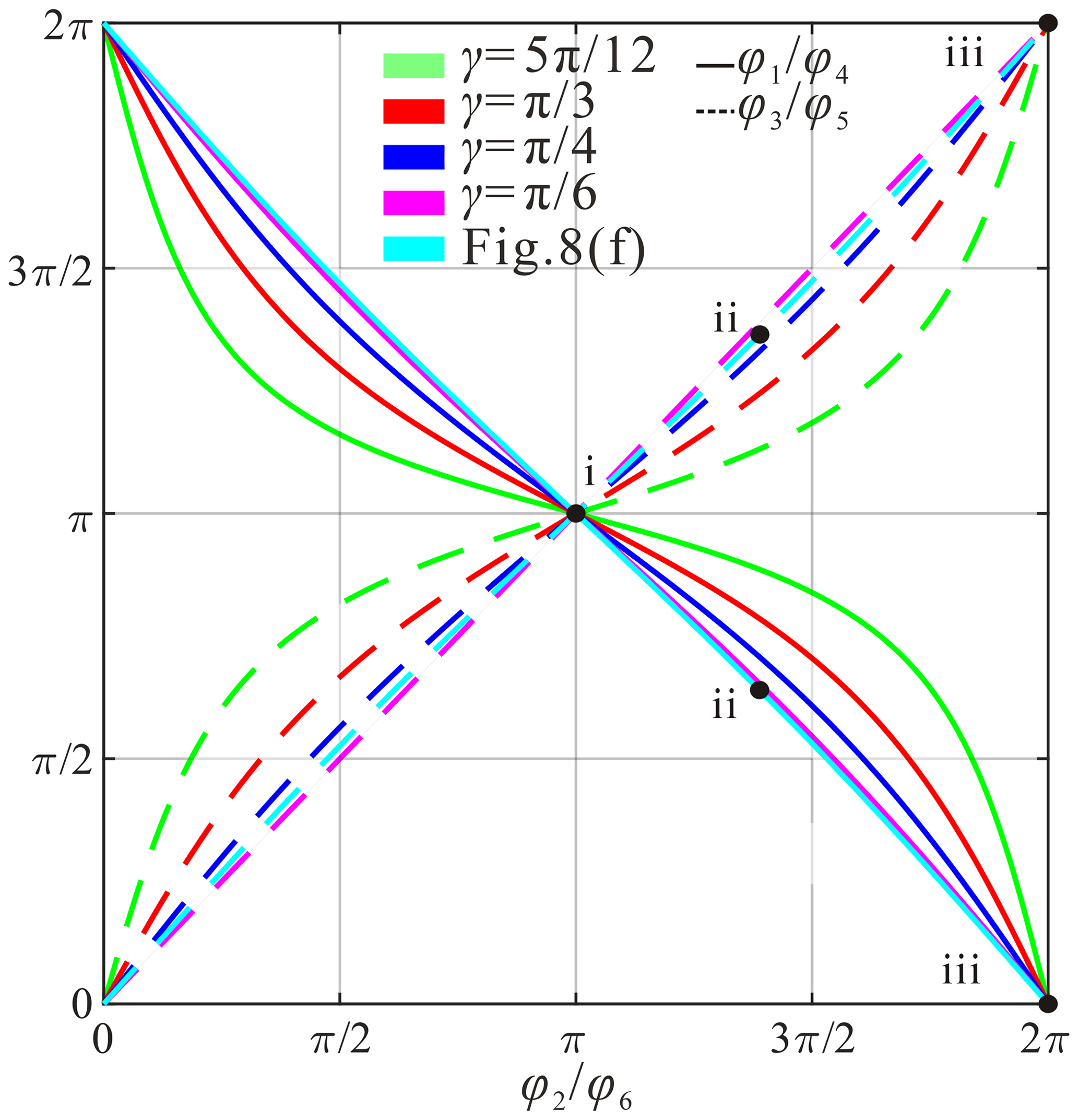
Figure 9The kinematic curves for scheme III among upper-dihedral angles φ1, φ3, φ4, φ5 vs. φ2(φ6).
In this situation, panels and are folded in the same direction regarding panel since creases BB′ and BB′′ are both mountain creases (see Fig. 8b). If β is not large enough, panel will intersect with , a physical model with parameters , , was fabricated with card paper as shown in Fig. 8e. The interference area gradually increases with the folding process and becomes the largest value at the fully folded configuration. To show the condition of avoiding the interference, Fig. 8c gives the fully folded configuration theoretically without considering interference. If
then there is no common area between panels and , and there will be no interference during the folding (see Fig. 8d). Namely, the condition of avoiding interference for this scheme is
The distance between A and C (see Fig. 8d) is
Due to β<π,
Therefore, the scheme could not realize the desired function even if the interference is avoided. The result is verified with a physical model, , , , with no interference, as shown in Fig. 8f, in which the top panel was removed to show AC in sub-figure (iv).
The paper proposed symmetric kirigami patterns to realize the function that allows a round disc to pass through a smaller hole in a piece of paper by the systematic analysis of kinematics and folding behaviours. The condition for the four-crease pattern to enable the disc to pass through the smaller hole was given. For six-crease patterns, situations for are possible to realize the desired function, while the pattern with could not due to interference. By analysing the folded configuration, we found that will always make the gap achieve the largest value, and the solution from Tadashi Tokieda belongs to scheme II of the six-crease pattern, , and . The patterns provide an effective way to enable bigger objects to pass through smaller holes. The process of finding the distribution of creases can be used as a reference for similar inverse folding problems and helps deepen understanding of the mechanisms and machine theory.
The data are available upon request from the corresponding author.
FY and HF are the lead authors of this paper, and initialized the study with AC. FY, WL, and KC wrote the paper. WL and KC studied the kinematics and made the models under the supervision of FY and HF. YG and HF checked and revised the paper.
The contact author has declared that neither they nor their co-authors have any competing interests.
Publisher's note: Copernicus Publications remains neutral with regard to jurisdictional claims in published maps and institutional affiliations.
The authors would like to give sincere thanks to Xiezhao Lin for the proposal and the discussion of studying the toy problem and to anonymous reviewers for their comprehensive comments and valuable suggestions to improve the paper.
This research has been supported by the National Natural Science Foundation of China (grant no. 51905101), the Natural Science Foundation of Fujian Province (grant no. 2019J01209), and the Fuzhou University (2021 First-class Undergraduate Course Construction).
This paper was edited by Francisco Romero and reviewed by three anonymous referees.
Chen, Y., Peng, R., and You, Z.: Origami of thick panels, Science, 349, 396–400, https://doi.org/10.1126/science.aab2870, 2015.
Chiang, C. H.: Kinematics of Spherical Mechanisms, Cambridge University Press, New York, 1988.
Dai, J. S.: Screw algebra and kinematic approaches for mechanisms and robotics, Springer, London, 2014.
Denavit, J. and Hartenberg, R. S.: A kinematic notation for lower-pair mechanisms based on matrices, J. Appl. Mech., 22, 215–221, https://doi.org/10.1115/1.4011045, 1955.
Deng, A., Ji, B., Zhou, X., and You, Z.: Geometric design and mechanical properties of foldcores based on the generalized Resch patterns, Thin-Wall. Struct., 148, 106516, https://doi.org/10.1016/j.tws.2019.106516, 2020.
Fang, H., Chu, S. A., Xia, Y., and Wang, K.: Programmable Self-Locking Origami Mechanical Metamaterials, Adv. Mater., 30, 15, e1706311, https://doi.org/10.1002/adma.201706311, 2018.
Feng, H., Chen, Y., Dai, J., and Gogu, G.: Kinematic study of the general plane-symmetric Bricard linkage and its bifurcation variations, J. Mechanisms, 116, 89–104, https://doi.org/10.1016/j.mechmachtheory.2017.05.019, 2017.
Haran, B.: Round Peg in a Square Hole – Numberphile, available at: https://www.youtube.com/watch?v=AvFNCNOyZeE, last access: 5 August 2021.
Hou, Y., Neville, R., Scarpa, F., Remillat, C., Gu, B., and Ruzzene, M.: Graded conventional-auxetic Kirigami sandwich structures: Flatwise compression and edgewise loading, Compos. Part B-Eng., 59, 33–42, https://doi.org/10.1016/j.compositesb.2013.10.084, 2014.
Huang, Z.: The kinematic and Type Synthesis of Lower – Mobility Parallel Manipulators, in: Proceedings of the 11th World Congress in Mechanism and Machine Science, 1–4 April 2004, Tianjin, China, 65–76, 2004.
Hull, T.: On the mathematics of flat origamis, Numer, 100, 205–224, 1994.
Hull, T. and Tachi, T.: Double-line rigid origami, conference paper, Proceedings of the 11th Asian Forum on Graphic Science (AFGS 2017), Tokyo, 6–10 August 2017, arXiv [preprint], arXiv:1709.03210, 11 September 2017.
Lee, D., Kim, S., Kim, J., Park, J., and Cho, K.: Origami Wheel Transformer: A Variable-Diameter Wheel Drive Robot Using an Origami Structure, Soft Robotics, 4, 163–180, https://doi.org/10.1089/soro.2016.0038, 2017.
Lee, D., Kim, J., Sohn, C., and Heo, J.: High–load capacity origami transformable wheel, Science Robotics, 6, 53, https://doi.org/10.1126/scirobotics.abe0201, 2021.
Lin, S., Xie, Y. M., Li, Q., Huang, X., and Zhou, S.: A kirigami approach to forming a synthetic buckliball, Sci. Rep.-UK, 6, 33016, https://doi.org/10.1038/srep33016, 2016.
Liu, S. Y. and Chen, Y.: Myard linkage and its mobile assemblies, Mech. Mach. Theory, 44, 1950–1963, https://doi.org/10.1016/j.mechmachtheory.2009.05.001, 2009.
Marras, A. E., Su, H. J., and Castro, C.: Design of DNA Origami Machines and Mechanisms, in: ASME 2019 ASME International Design Engineering Technical Conferences, 18–21 August 2019, Anaheim, CA, https://doi.org/10.1115/IMECE2012-87848, 2019.
Masayuki, E. and Hiroshi, S.: DNA Origami Nanomachines, Molecules, 23, 1766, https://doi.org/10.3390/molecules23071766, 2018.
Pesenti, M., Masera, G., and Fiorito, F.: Shaping an origami shading device through visual and thermal simulations, Enrgy. Proced., 78, 346–351, https://doi.org/10.1016/j.egypro.2015.11.663, 2015.
Rafsanjani, A., Zhang, Y., Liu, B., Rubinstein, S. M., and Bertoldi, K.: Kirigami skins make a simple soft actuator crawl, Science Robotics, 3, eaar7555, https://doi.org/10.1126/scirobotics.aar7555, 2018.
Wang, X., Guest, S. D., and Kamien, R. D.: Keeping It Together: Interleaved Kirigami Extension Assembly, Phys. Rev. X, 10, 011013, https://doi.org/10.1103/physrevx.10.011013, 2020.
Yang, Y., Vella, K., and Holmos, D. P: Grasping with kirigami shells, Science Robotics, 6, 54, https://doi.org/10.1126/SCIROBOTICS.ABD6426, 2021.
Yu, Y., Chen, Y., and Paulino, G. H.: On the unfolding process of triangular Resch patterns: a finite particle method investigation, in: Proceedings of the ASME 2019 International Design Engineering Technical Conferences, 18–21 August 2019, Anaheim, CA, USA, V05BT07A048, https://doi.org/10.1115/DETC2019-98121, 2019.
Zhang, X. and Chen, Y.: Mobile assemblies of Bennett linkages from four-crease origami patterns, P. Roy. Soc. A, 474, 2210, https://doi.org/10.1098/rspa.2017.0621, 2018.
Zhang, X. and Chen, Y.: Vertex-splitting on a diamond origami pattern, J. Mech. Robot., 11, 031014, https://doi.org/10.1115/1.4043214, 2019.
Zhang, Y., Yan, Z., Nan, K., and Xiao, D.: A mechanically driven form of kirigami as a route to 3D mesostructures in micro/nanomembranes, P. Natl. Acad. Sci. USA, 112, 11757–11764, https://doi.org/10.1073/pnas.1515602112, 2015.